

LG HT503THW-AH User manual
Model: HT503THW(HT503THW-AH, SH53TH-S/C/W, W93-T/R)
Unique Features
P/NO : MFL56941196
5.1ch ez Set-up
Listen sound from TV, DVD
and Digital Device with vivid
5.1ch mode.
Go to page 18
Full HD up-scaling
(1080p)
View Full HD picture quality
with simple setup.
Go to page 13
USB Direct Recording
Record music from CD to
your USB device.
Go to page 20
Portable In
Listen to music from your
portable device (MP3,
Notebook, etc).
Go to page 20
HT503THW_AH_BAGOILK_ENG_1196 8/11/08 9:43 AM Page 1
2
CAUTION: TO REDUCE THE RISK OF ELECTRIC SHOCK DO NOT REMOVE
COVER (OR BACK) NO USER-SERVICEABLE PARTS INSIDE REFER SERVICING
TO QUALIFIED SERVICE PERSONNEL.
This lightning flash with arrowhead symbol within an equilateral triangle is
intended to alert the user to the presence of uninsulated dangerous voltage
within the product’s enclosure that may be of sufficient magnitude to constitute a risk of electric shock to persons.
The exclamation point within an equilateral triangle is intended to alert the
user to the presence of important operating and maintenance (servicing)
instructions in the literature accompanying the product.
WARNING: TO PREVENT FIRE OR ELECTRIC SHOCK HAZARD, DO NOT
EXPOSE THIS PRODUCT TO RAIN OR MOISTURE.
WARNING: Do not install this equipment in a confined space such as a book case or
similar unit.
CAUTION: Do not block any ventilation openings. Install in accordance with the manufacturer's instructions.
Slots and openings in the cabinet are provided for ventilation and to ensure reliable
operation of the product and to protect it from over heating. The openings should be
never be blocked by placing the product on a bed, sofa, rug or other similar surface.
This product should not be placed in a built-in installation such as a bookcase or rack
unless proper ventilation is provided or the manufacturer's instruction has been
adhered to.
CAUTION: This product employs a Laser System.
To ensure proper use of this product, please read this owner’s
manual carefully and retain it for future reference. Should the
unit require maintenance, contact an authorized service center.
Use of controls, adjustments or the performance of procedures
other than those specified herein may result in hazardous radiation exposure.
To prevent direct exposure to laser beam, do not try to open the enclosure. Visible
laser radiation when open. DO NOT STARE INTO BEAM.
CAUTION: The apparatus should not be exposed to water (dripping or splashing) and
no objects filled with liquids, such as vases, should be placed on the apparatus.
CAUTION concerning the Power Cord
Most appliances recommend they be placed upon a dedicated circuit;
That is, a single outlet circuit which powers only that appliance and has no additional
outlets or branch circuits. Check the specification page of this owner's manual to be
certain.
Do not overload wall outlets. Overloaded wall outlets, loose or damaged wall outlets,
extension cords, frayed power cords, or damaged or cracked wire insulation are dangerous. Any of these conditions could result in electric shock or fire. Periodically
examine the cord of your appliance, and if its appearance indicates damage or deterioration, unplug it, discontinue use of the appliance, and have the cord replaced with
an exact replacement part by an authorized service center.
Protect the power cord from physical or mechanical abuse, such as being twisted,
kinked, pinched, closed in a door, or walked upon. Pay particular attention to plugs,
wall outlets, and the point where the cord exits the appliance.
To disconnect power from the mains, pull out the mains cord plug. When installing the
product, ensure that the plug is easily accessible.
Safety Precaution
CAUTION
RISK OF ELECTRIC SHOCK
DO NOT OPEN
HT503THW_AH_BAGOILK_ENG_1196 8/11/08 9:43 AM Page 2
3
Contents
Setting up . . . . . . . . . . . . . . . . . . . . . . . . . . . . . . . .4-6
LED indicator of Wireless Transmitter . . . . . . . . . . . . .7
LED indicator of Wireless Receiver . . . . . . . . . . . . . .7
Setting an ID of Wireless Transmitter . . . . . . . . . . . . .7
Hooking up the unit . . . . . . . . . . . . . . . . . . . . . . . . .8-9
Remote control . . . . . . . . . . . . . . . . . . . . . . . . . . . .10
Main Unit . . . . . . . . . . . . . . . . . . . . . . . . . . . . . . . . .11
OSD Initial language settings . . . . . . . . . . . . . . . . . .12
Initial Setting the Area Code . . . . . . . . . . . . . . . . . . .12
Adjust the settings . . . . . . . . . . . . . . . . . . . . . . . .12-14
Setting the sound mode . . . . . . . . . . . . . . . . . . . . . .14
Displaying Disc Information . . . . . . . . . . . . . . . . . . .15
Playing a disc or file . . . . . . . . . . . . . . . . . . . . . .15-17
Viewing photo files . . . . . . . . . . . . . . . . . . . . . . . . . .17
Listening to the radio . . . . . . . . . . . . . . . . . . . . . . . .18
5.1ch ez Set-up . . . . . . . . . . . . . . . . . . . . . . . . . . . .18
Listening to music from your USB device . . . . . . . . .19
Recording music from CD to your USB device . . . . .20
Listening to music from your portable player . . . . . . .20
Language Codes . . . . . . . . . . . . . . . . . . . . . . . . . . .21
Area Codes . . . . . . . . . . . . . . . . . . . . . . . . . . . . . . .21
Troubleshooting . . . . . . . . . . . . . . . . . . . . . . . . . . . .22
Types of Playable Discs . . . . . . . . . . . . . . . . . . . . . .23
Specifications . . . . . . . . . . . . . . . . . . . . . . . . . . . . . .24
What is SIMPLINK?
Some functions of this unit are controlled by TV’s remote control when this unit and
LG TV with SIMPLINK are connected through HDMI connection.
• Controllable functions by LG TV’s remote control; Play, Pause, Scan, Skip, Stop,
Power Off, etc.
• Refer to the TV owner’s manual for the details of SIMPLINK function.
• LG TV with SIMPLINK function has the logo as shown above.
• Use a higher version cable than 1.2A HDMI cable.
Welcome to your new DVD Receiver
POWER: This unit operates on a mains supply of 200-240V, 50/60Hz.
WIRING: This unit is supplied with a BSI 1363 approved 13 amp mains plug, fused
at 5 amp. When replacing the fuse always use a 5 amp BS 1362, BSI or ASTA
approved type. Never use this plug with the fuse cover omitted. To obtain a replace-
ment fuse cover contact your dealer. If the type of plug supplied is not suitable for
the mains sockets in your home, then the plug should be removed and a suitable
type fitted. Please refer to the wiring instructions below:
WARNING: A mains plug removed from the mains lead of this DVD player must be
destroyed. A mains plug with bared wires is hazardous if inserted in a mains socket.
Do not connect either wire to the earth pin, marked with the letter E or with the earth
symbol or coloured green or green and yellow. If any other plug is fitted, use a
5 amp fuse, either in the plug, or at the distribution board.
IMPORTANT: The wires in this mains lead are coloured in accordance with the fol-
lowing codes:
- BLUE: NEUTRAL, BROWN: LIVE - As the colours of the wires in the mains lead
of this DVD player may not correspond with the coloured marking identifying the ter-
minals in your plug, proceed as follows: The wire which is coloured blue must be
connected to the terminal which is marked with the letter N or coloured black. The
wire which is coloured brown must be connected to the terminal which is marked
with the letter L or coloured red.
In NIGERIA
HT503THW_AH_BAGOILK_ENG_1196 8/11/08 9:43 AM Page 3
4
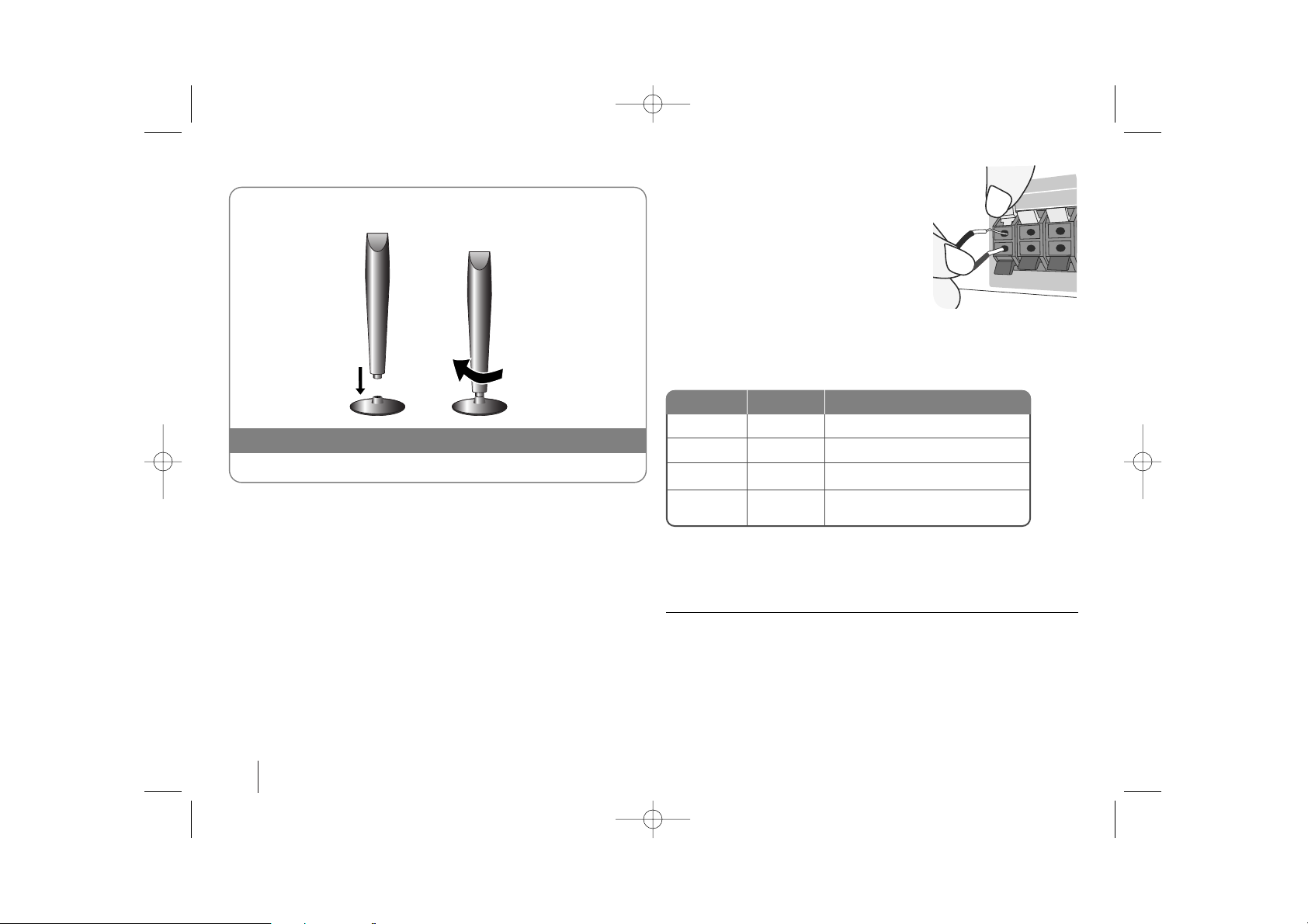
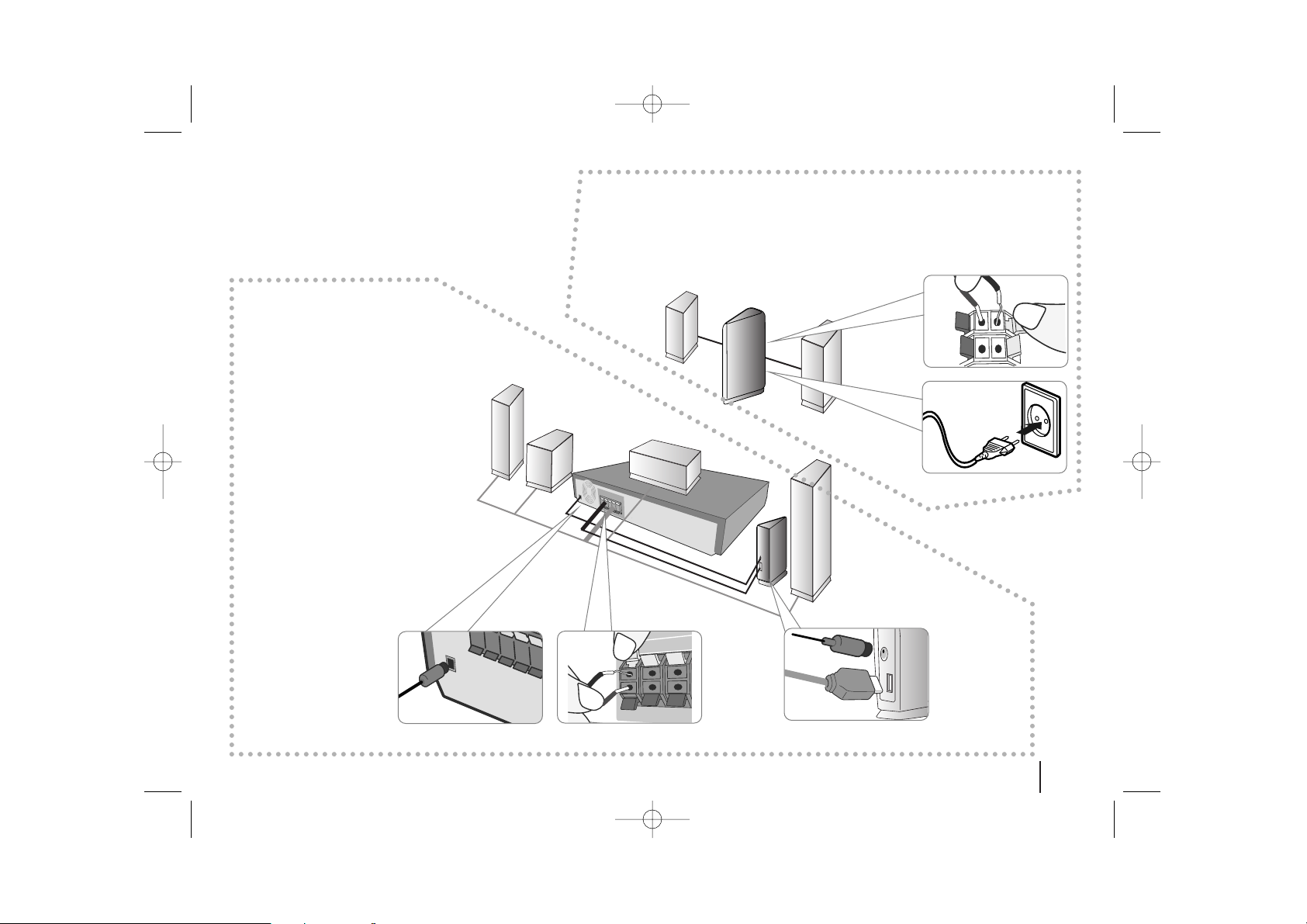
Setting up
Connect the red end of each wire to the
terminals marked +(plus) and the black
end to the terminals marked - (minus).
cc
Connect the wires to the speakers.
Connect the other end of each wire to the correct speaker according to
the colour coding
:
To connect the cable to the speakers, press each plastic finger pad to open the
connection terminals on the base of each speaker. Insert the wire and release
the finger pad.
Be careful of the following
Be careful to make sure children do not put their hands or any objects into the
*speaker duct.
*Speaker duct: A hall for plentiful bass sound on speaker cabinet(enclosure).
Attaching the speakers to the DVD receiver
aa
You will have received six speaker cables.
Each one is colour-coded by a band near each end and connects one of
the six speakers to the DVD receiver.
bb
Connect the wires to the DVD receiver.
Match each wire’s coloured band to the same coloured connection terminal on the rear of the DVD receiver. To connect the cable to the DVD
receiver, press each plastic finger pad to open the connection terminal.
Insert the wire and release the finger pad.
Fix the speaker to the base by rotating the speaker
The speakers are detached from the speaker stands.
Assembling the Speakers
Green
Orange
Red
White
Centre
Sub Woofer
Front
Front
Above screen, directly in front of you.
In front of yo u, to the right of
the screen.
In front of you, to the left of
the screen.
POSITION
SPEAKER
COLOUR
HT503THW_AH_BAGOILK_ENG_1196 8/11/08 9:43 AM Page 4
5
Setting up
Attaching the speakers to the Wireless Receiver
aa
Connect the power cord of the Wireless Receiver to the outlet.
bb
Connect the wires to the Wireless Receiver.
Connect the Wireless Receiver and the rear speaker (right, left) with the speaker cable.
aa
bb
Attaching the
Wireless Transmitter
to the DVD receiver
aa
Connect the DC power
cable to the unit and transmitter.
bb
Connect the SOUND SIGNAL connector of the
Wireless Transmitter and
rear (right, left) speaker of
the main set with the
sound signal cable.
aa
aa
bb
bb
HT503THW_AH_BAGOILK_ENG_1196 8/11/08 9:43 AM Page 5
6
Be careful of the following
• Set the distance between this unit and Wireless Receiver within 10m.
• Optimum performance can be implemented only when the Wireless
Transmitter and the Wireless Receiver within distance of 2m to 10m is used
since communication failure may occur if longer distance is used.
• Be sure to match the speaker cable to the appropriate terminal on the components: + to + and – to –. If the cables are reversed, the sound will be distorted and will lack bass.
•
It takes a few seconds (and may take longer) for the
Wireless Transmitter
and
Wireless Receiver
to communicate with each other.
• When the unit is turned off, the Wireless Transmitter is in standby mode (off)
automatically after about 10 seconds.
• If the Wireless Transmitter is turned off, the Wireless Receiver will not function.
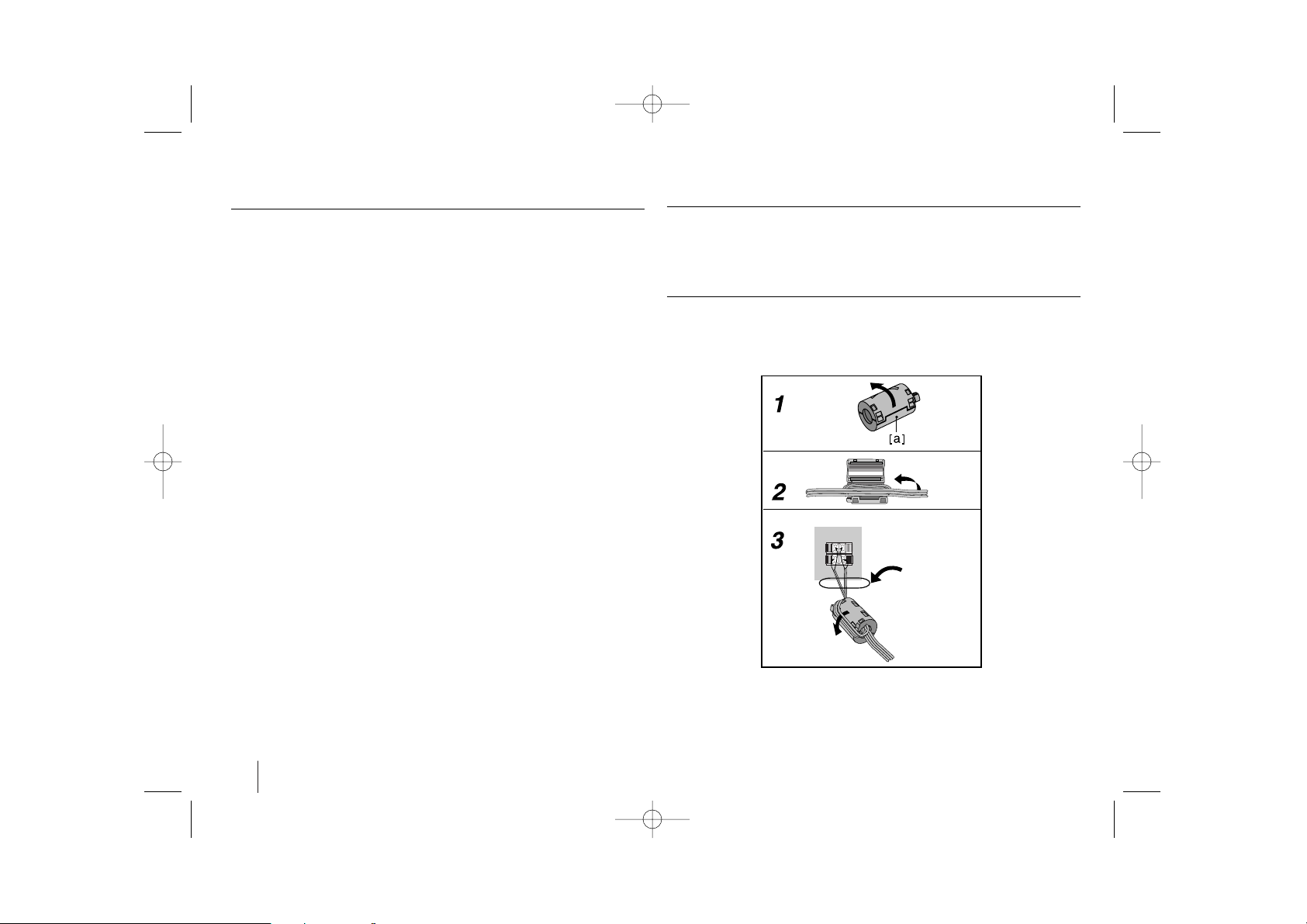
About Ferrite Core - optional
Be sure to attach the ferrite core to the speaker cables (for connecting to
this unit).
This ferrite core can reduce noises.
How to attach the ferrite core - optional
1 Press the stopper [a] of the ferrite core to open.
2 Wind the cable once on the ferrite core. Attach the ferrite core near the
unit (Refer to the fig.3 and comment.).
3 Close the ferrite core until it clicks.
(fig.3)
Setting up
The length
here is as
short as
possible.
HT503THW_AH_BAGOILK_ENG_1196 8/11/08 9:43 AM Page 6

7
Be careful of the following
If there is a strong electromagnetic wave product nearby, interference may
occur. Put the unit (Wireless Receiver and main unit) away from there.(Ex:
Microwave oven)
If there is no audio signal for longer than 10 minutes, the Wireless Receiver
and Wireless Transmitter will be automatically switched to standby mode. In
power saving mode, both LEDs will turn red. LEDs will turn blue when there is
any audio signal back.
If you operate main unit then wireless speakers (rear speakers) sound within a
few seconds in standby mode.
LED indicator of Wireless
Transmitter
BLUE The main set is turned on, everything is connected
and transmitting.
RED The wireless transmitter is in standby mode.
OFF (No display) The DC cable is disconnected to the unit.
LED color
Operation
LED indicator of Wireless
Receiver
BLUE
The
Wireless Receiver is receiving a signal of
wireless transmitter
.
RED The Wireless Receiver is in standby mode.
OFF (No display) The Wireless Receiver is turned off.
LED color
Operation
Setting an ID of Wireless
Transmitter
1 Connect the SOUND SIGNAL connector of
transmitter and the rear (right, left) speaker
terminals of main unit with the SOUND
SIGNAL cable.:-
2 Connect the DC IN connector of transmitter
and the transmitter connector of main unit with
the DC power cable.: -
3Turn off the Wireless Receiver: POWER Switch
4 Press the ID. for more than 3 seconds:
The Blue LED indicator will quickly flicker ID.
5Turn on the Wireless Receiver: POWER Switch
When the unit is manufactured, the ID is already set. If an interference
occurs or you use a new Wireless Receiver, an ID is set again.
ON Wireless Kit
HT503THW_AH_BAGOILK_ENG_1196 8/11/08 9:43 AM Page 7
8
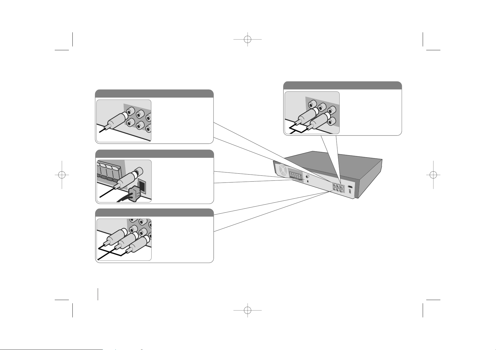
Hooking up the unit
a Connect jacks on the unit and your TV (DVD player or Digital Device etc.) using the cables.
b Plug the power cord into the power source.
Audio In connection
The unit’s Audio jacks are
colour coded (red for right
audio and white for left
audio). If your TV has only
one input for audio (mono),
connect it to the left (white)
audio jack on the unit.
AM/FM connection
AM - Connect the AM loop
aerial to the DVD receiver.
FM - Connect the FM aerial.
The reception will be its best
when the two loose ends of
the aerial are in a straight and
horizontal line.
Video Out connection
Connect the VIDEO OUTPUT (MONITOR) jack on the
unit to the corresponding
input jack on your TV using a
Video cable.
Component Video connection
Connect the COMPONENT
VIDEO (PROGRESSIVE
SCAN) OUTPUT jacks on
the unit to the corresponding
input jacks on your TV using
a Y PB PR cable.
HT503THW_AH_BAGOILK_ENG_1196 8/11/08 9:43 AM Page 8
 Loading...