

Page 1

MODEL: HR822TSERVICE MANUAL
Internal Use Only
Website http://biz.lgservice.com
BLU-RAY DISC PLAYER
with BUILT-IN HDD & HD TUNER
SERVICE MANUAL
P/NO : AFN75494605 JANUARY, 2012
MODEL: HR822T
CAUTION
BEFORE SERVICING THE UNIT, READ THE “SAFETY PRECAUTIONS”
IN THIS MANUAL.
Page 2

CONTENTS
SECTION 1 ........ SUMMARY
SECTION 2 ........ CABINET & MAIN CHASSIS
SECTION 3 ........ ELECTRICAL
SECTION 4 ........ BCM7632 F/E LOADER PART
SECTION 5 ........ REPLACEMENT PARTS LIST
1-1
Page 3

SECTION 1
SUMMARY
CONTENTS
PRODUCT SAFETY SERVICING GUIDELINES
FOR HD RECORDER / BLU-RAY COMBO PRODUCTS .............................................................. 1-3
SERVICING PRECAUTIONS ................................................................................................................... 1-4
• GENERAL SERVICING PRECAUTIONS
• INSULATION CHECKING PRODEDURE
• ELECTROSTATICALLY SENSITIVE (ES) DEVICES
PROGRAM UPDATE GUIDE ................................................................................................................... 1-5
1. MAKING SOFTWARE UPGRADE TO USB OR DISC ............................................................................. 1-5
2. SOFTWARE UPGRADE ........................................................................................................................... 1-6
3. NETWORK UPDATE ................................................................................................................................ 1-7
4. SYSTEM INFORMATION ......................................................................................................................... 1-9
SPECIFICATIONS ..................................................................................................................................... 1-10
1-2
Page 4
PRODUCT SAFETY SERVICING GUIDELINES
FOR HD RECORDER / BLU-RAY COMBO PRODUCTS
IMPORTANT SAFETY NOTICE
This manual was prepared for use only by properly trained audio-video service
technicians.
When servicing this product, under no circumstances should the original design be
modified or altered without permission from LG Corporation. All components should
be replaced only with types identical to those in the original circuit and their physical
location, wiring and lead dress must conform to original layout upon completion of
repairs.
Special components are also used to prevent x-radiation, shock and fire hazard.
These components are indicated by the letter “x” included in their component designators and are required to maintain safe performance. No deviations are allowed
without prior approval by LG Corporation.
Circuit diagrams may occasionally differ from the actual circuit used. This way,
implementation of the latest safety and performance improvement changes into the
set is not delayed until the new service literature is printed.
CAUTION : Do not attempt to modify this product in any way. Never perform cus-
tomized installations without manufacturer’s approval. Unauthorized modifications
will not only void the warranty, but may lead to property damage or user injury.
Service work should be performed only after you are thoroughly familiar with these
safety checks and servicing guidelines.
GRAPHIC SYMBOLS
The exclamation point within an equilateral triangle is intended to alert
the service personnel to important safety information in the service
literature.
The lightning flash with arrowhead symbol within an equilateral triangle is intended to alert the service personnel to the presence of noninsulated “dangerous voltage” that may be of sufficient magnitude to
constitute a risk of electric shock.
The pictorial representation of a fuse and its rating within an equilateral triangle is intended to convey to the service personnel the following fuse replacement caution notice:
CAUTION : FOR CONTINUED PROTECTION AGAINST RISK OF
FIRE, REPLACE ALL FUSES WITH THE SAME TYPE AND
RATING AS MARKED NEAR EACH FUSE.
SERVICE INFORMATION
While servicing, use an isolation transformer for protection from AC line shock. After
the original service problem has been corrected, make a check of the following:
FIRE AND SHOCK HAZARD
1. Be sure that all components are positioned to avoid a possibility of adjacent
component shorts. This is especially important on items trans-ported to and from
the repair shop.
2. Verify that all protective devices such as insulators, barriers, covers, shields, strain
reliefs, power supply cords, and other hardware have been reinstalled per the
original design. Be sure that the safety purpose of the polarized line plug has not
been defeated.
3. Soldering must be inspected to discover possible cold solder joints, solder
splashes, or sharp solder points. Be certain to remove all loose foreign particles.
4. Check for physical evidence of damage or deterioration to parts and components,
for frayed leads or damaged insulation (including the AC cord), and replace if
necessary.
5. No lead or component should touch a high current device or a resistor rated at 1
watt or more. Lead tension around protruding metal surfaces must be avoided.
6. After reassembly of the set, always perform an AC leakage test on all exposed
metallic parts of the cabinet (the channel selector knobs, antenna terminals,
handle and screws) to be sure that set is safe to operate without danger of electrical shock. DO NOT USE A LINE ISOLATION TRANSFORMER DURING THIS
TEST. Use an AC voltmeter having 5000 ohms per volt or more sensitivity in the
following manner: Connect a 1500 ohm, 10 watt resistor, paralleled by a .15 mfd
150V AC type capacitor between a known good earth ground water pipe, conduit,
etc.) and the exposed metallic parts, one at a time. Measure the AC voltage
across the combination of 1500 ohm resistor and .15 mfd capacitor. Reverse the
AC plug by using a non-polarized adaptor and repeat AC voltage measurements
for each exposed metallic part. Voltage measured must not exceed 0.75 volts
RMS. This corresponds to 0.5 milliamp AC. Any value exceeding this limit constitutes a potential shock hazard and must be corrected immediately.
TIPS ON PROPER INSTALLATION
1. Never install any receiver in a closed-in recess, cubbyhole, or closely fitting shelf
space over, or close to, a heat duct, or in the path of heated air flow.
2. Avoid conditions of high humidity such as: outdoor patio installations where dew
is a factor, near steam radiators where steam leakage is a factor, etc.
3. Avoid placement where draperies may obstruct venting. The customer should
also avoid the use of decorative scarves or other coverings that might obstruct
ventilation.
4. Wall- and shelf-mounted installations using a commercial mounting kit must follow
the factory-approved mounting instructions. A product mounted to a shelf or
platform must retain its original feet (or the equivalent thickness in spacers) to
provide adequate air flow across the bottom. Bolts or screws used for fasteners
must not touch any parts or wiring. Perform leakage tests on customized installations.
5. Caution customers against mounting a product on a sloping shelf or in a tilted
position, unless the receiver is properly secured.
6. A product on a roll-about cart should be stable in its mounting to the cart.
Caution the customer on the hazards of trying to roll a cart with small casters
across thresholds or deep pile carpets.
7. Caution customers against using extension cords. Explain that a forest of extensions, sprouting from a single outlet, can lead to disastrous consequences to
home and family.
1-3
Page 5

SERVICING PRECAUTIONS
CAUTION: Before servicing the HD RECORDER / BLU-RAY
COMBO covered by this service data and its supplements and
addends, read and follow the SAFETY PRECAUTIONS.
NOTE: if unforeseen circumstances create conflict between
the following servicing precautions and any of the safety precautions in this publications, always follow the safety precautions.
Remember Safety First :
General Servicing Precautions
1. Always unplug the HD RECORDER / BLU-RAY COMBO
AC power cord from the AC power source before:
(1) Removing or reinstalling any component, circuit board,
module, or any other assembly.
(2) Disconnecting or reconnecting any internal electrical
plug or other electrical connection.
(3) Connecting a test substitute in parallel with an electro-
lytic capacitor.
Caution : A wrong part substitution or incorrect polarity
installation of electrolytic capacitors may result in an
explosion hazard.
2. Do not spray chemicals on or near this HD RECORDER /
BLU-RAY COMBO or any of its assemblies.
Electrostatically Sensitive (ES) Devices
Some semiconductor (solid state) devices can be damaged
easily by static electricity. Such components commonly are
called Electrostatically Sensitive (ES) Devices. Examples of
typical ES devices are integrated circuits and some field effect
transistors and semiconductor chip components.
The following techniques should be used to help reduce the
incidence of component damage caused by static electricity.
1. Immediately before handling any semiconductor component
or semiconductor-equipped assembly, drain off any electrostatic charge on your body by touching a known earth
ground. Alternatively, obtain and wear a commercially available discharging wrist strap device, which should be
removed for potential shock reasons prior to applying power
to the unit under test.
2. After removing an electrical assembly equipped with ES
devices, place the assembly on a conductive surf ace such
as aluminum foil, to prevent electrostatic charge buildup or
exposure of the assembly.
3. Use only a grounded-tip soldering iron to solder or unsolder
ES devices.
3. Unless specified otherwise in this service data, clean electrical contacts by applying an appropriate contact cleaning
solution to the contacts with a pipe cleaner, cotton-tipped
swab, or comparable soft applicator.
Unless specified otherwise in this service data, lubrication of
contacts is not required.
4. Do not defeat any plug/socket B+ voltage interlocks with
whitch instruments covered by this service manual might be
equipped.
5. Do not apply AC power to this HD RECORDER / BLU-RAY
COMBO and / or any of its electrical assemblies unless all
solidstate device heat sinks are correctly installed.
6. Always connect the test instrument ground lead to an appropriate ground before connecting the test instrument positive
lead. Always remove the test instrument ground lead last.
Insulation Checking Procedure
Disconnect the attachment plug from the AC outlet and turn
the power on. Connect an insulation resistance meter (500V)
to the blades of the attachment plug. The insulation resistance
between each blade of the attachment plug and accessible
conductive parts (Note 1) should be more than 1Mohm.
Note 1 : Accessible Conductive Parts include Metal panels,
Input terminals, Earphone jacks,etc.
4. Use only an anti-static solder removal device. Some solder
removal devices not classified as “anti-static” can generate
electrical charges sufficient to damage ES devices.
5. Do not use freon-propelled chemicals. These can generate
an electrical charge sufficient to damage ES devices.
6. Do not remove a replacement ES device from its protective
package until immediately before you are ready to install it.
(Most replacement ES devices are packaged with leads
electrically shorted together by conductive foam, aluminum
foil,or comparable conductive material).
7. Immediately before removing the protective material from
the leads of a replacement ES device, touch the protective
material to the chassis or circuit assembly into which the
device will be installed.
Caution: Be sure no power is applied to the chassis or cir-
cuit, and observe all other safety precautions.
8. Minimize bodily motions when handling unpackaged replacement ES devices. (Normally harmless motion such as the
brushing together of your clothes fabric or the lifting of your
foot from a carpeted floor can generate static electricity sufficient to damage an ES device.)
1-4
Page 6

PROGRAM UPDATE GUIDE
1. MAKING SOFTWARE UPGRADE TO USB OR DISC
1-1. Software Upgrade to Disc
1) Do Physical format as ISO9660 or JOLIET fi le system
2) Don’t care about the CD Volume label
3) Write Main SW fi le and Back up SW fi le on Root
a) Main SW : LG_BR_7000B32.ROM-00
b) Back up SW : LG_BR_7000B32.ROM-01
1-2. Software Upgrade to USB
1) Write Main SW fi le and Back up SW fi le :
a) Main SW : LG_BR_7000B32.ROM-00
b) Back up SW : LG_BR_7000B32.ROM-01
2) Copy this fi le to root fold in USB.
1-5
Page 7
PROGRAM UPDATE GUIDE
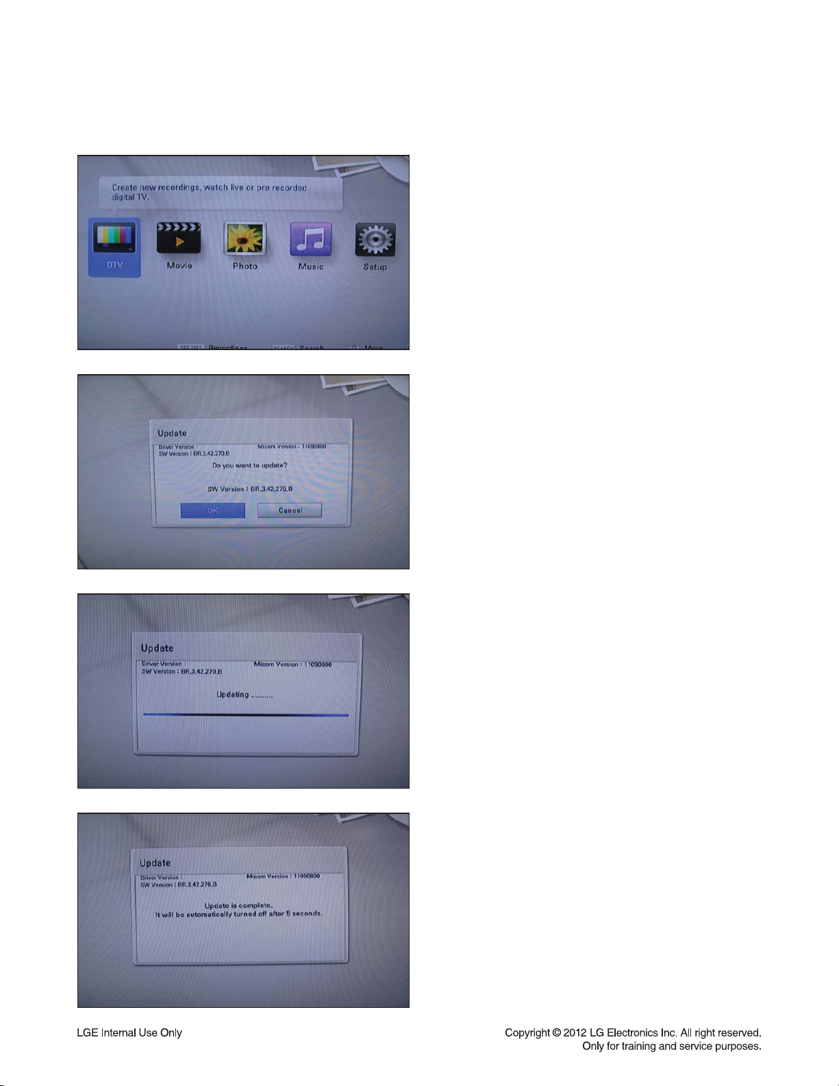
2. SOFTWARE UPGRADE
1) Select “Home” button in Remocon.
2) Insert upgrading USB or Disc to set.
3) After about 10 seconds, system display a pop-up for
program upgrade.
4) Move cursor to “OK” in pop-up and press “ENTER”
key.
It will show progress information.
5) If the upgrade process is complete, the set will be
automatically turned off.
1-6
Page 8
PROGRAM UPDATE GUIDE
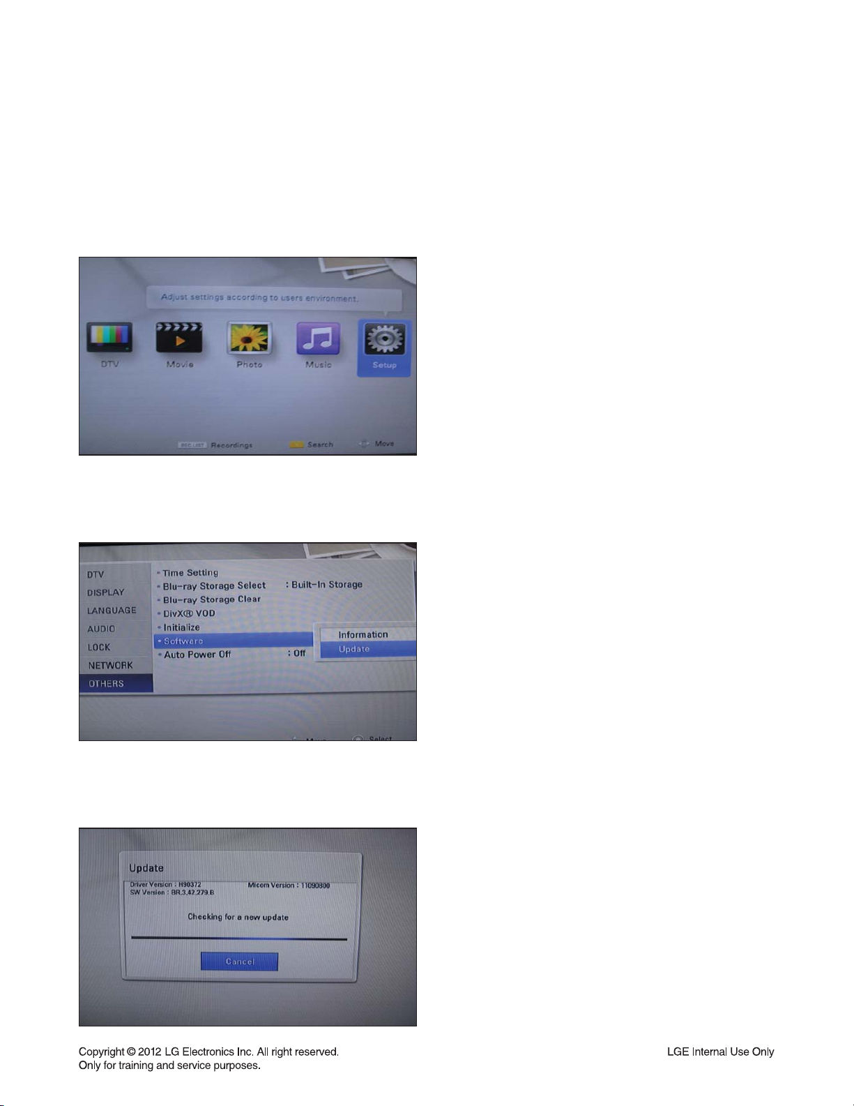
3. NETWORK UPDATE
You can update the fi rmware by connecting your unit device directly to the S/W update server.
Confi guring Network Settings
To update the fi rmware by connecting your player directly to the S/W update server, your player must be con-
nected to network. If your player is not connected to network, make a physical connection.
1) Select “Home” button in Remocon, and select the
Setup mode.
2) Select Others --> Software Update
3) On the UPDATE window, press or ENTER to check
for the newest update.
(Checking will takes about one minute.)
Caution:
Pressing Enter while checking for the update will end
process.
1-7
Page 9
NETWORK UPDATE
PROGRAM UPDATE GUIDE
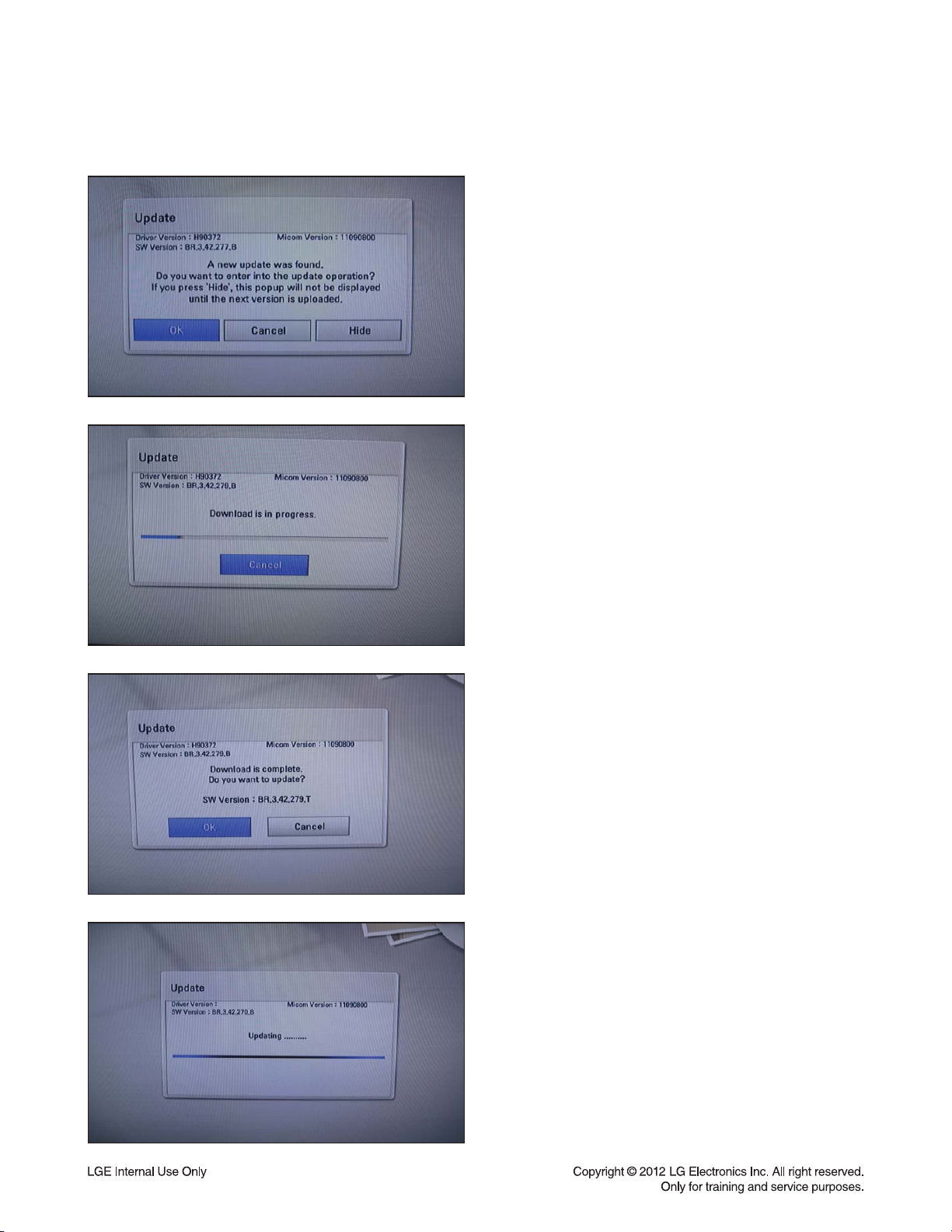
If newer version exists,
4) If newer version exists, the message “A new update
was found. Do you want to download it ?”
appears. Select OK to download the update.
(Selecting CANCEL will end the update.)
5) The player starts downloading the newest update
from the SBP server.
6) When downloading is completed, the message,
“Download is complete. Do you want to update?”
appears.
7) Select OK to start updating.
8) Update will be processed.
Caution:
Do not turn off the power during fi rmware update.
1-8
Page 10
PROGRAM UPDATE GUIDE
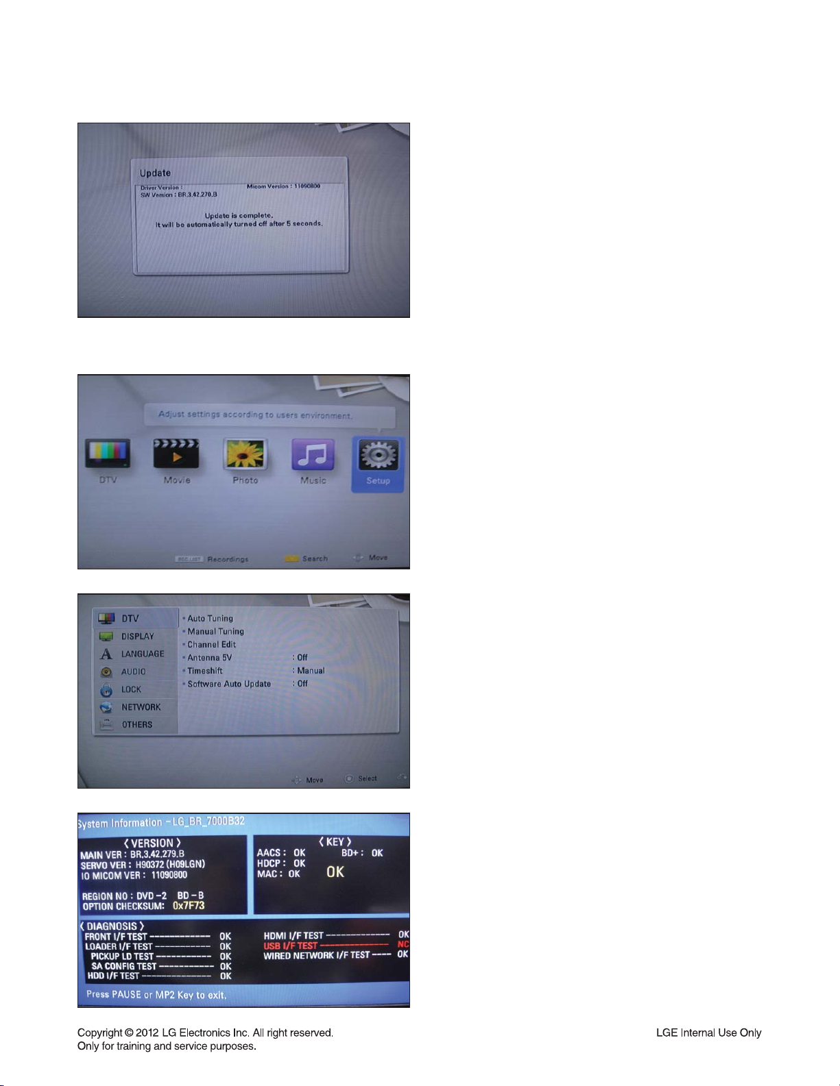
4. SYSTEM INFORMATION
9) When update is completed, the message, “Update
is complete.” will appear, and the power will turn off
automatically after 5 seconds.
10) Turn the power back on.
The system now operates with the new version.
1) Press “Home” button in Remocon.
2) Select “Setup” in Home Menu
3)
Press button number 1 –> 3 –> 9 –> 7 –> 1 –> 3 –> 9
in Remocon.
The picture on TV screen appears like left picture:
4) Press “Pause” button in Remocon to exit.
1-9
Page 11

SPECIFICATIONS
• GENERAL
Power requirements: AC 200 ~ 240 V, 50 / 60 Hz
Power consumption: 30 W
Dimensions (approx.) : 430 X 58 X 299 mm (W x H x D) without foot
Net weight (approx.) : 3.33 kg
Operating temperature : 5 °C to 35 °C
Operating humidity : 5 % to 90 %
Television system : DVB-T Standard Compliant
• TV RECORDING
Recording format: TS (Transport Stream format)
Recordable media: Hard Disc Drive (250 GB), USB 2.0 HDD
Audio recording format: Dolby Digital (2 CH)
• CONNECTORS
VIDEO OUT: 1.0 V (p-p), 75 Ω, sync negative, RCA jack x 1
HDMI OUT (video/audio): 19 pin (HDMI standard, Type A)
ANALOG AUDIO OUT: 2.0 Vrms (1 kHz, 0 dB), 600 Ω, RCA jack (L, R) x 1 / SCART x 1
DIGITAL OUT (COAXIAL): 0.5 V (p-p), 75 Ω, RCA jack x 1
USB Port: 4 pin (USB 2.0 standard)
ANTENNA IN: Antenna input, 75 Ω
• SYSTEM
Laser: Semiconductor laser
Wavelength: 405 nm / 650 nm
Frequency response: 20 Hz to 20 kHz (48 kHz, 96 kHz, 192 kHz sampling)
Signal-to-noise ratio: More than 100 dB (Analog OUT connectors only)
Harmonic distortion: Less than 0.008 %
Dynamic range: More than 95 dB
LAN port: Ethernet jack x 1, 10BASE-T / 1—BASE-TX
Bus Power Supply (USB): DC 5 V 500 mA
Note : Design and specifications are subject to change prior notice.
1-10
Page 12

SECTION 2
CABINET & MAIN CHASSIS
CONTENTS
EXPLODED VIEWS ..................................................................................................................................... 2-2
1. CABINET AND MAIN FRAME SECTION ................................................................................................. 2-2
2. DECK MECHANISM SECTION, BM12H2 (LG08) .................................................................................... 2-3
3. PACKING ACCESSORY SECTION ......................................................................................................... 2-4
2-1
Page 13

EXPLODED VIEWS
1. CABINET AND MAIN FRAME SECTION
462
250
OPTIONAL PARTS
104
G
F
CABLE11
CABLE10
A26
410
462
462
G
101
F
MAIN
A46
BOARD
E
D
C
B
462
320
465
A
A47
B
C
474
D
SMPS
BOARD
300
474
462
E
CABLE1
A50
462
275
TIMER
BOARD
284
283
462
287
A43
465
268
267
A
261
261
261A
261
A44
260
2-2
Page 14
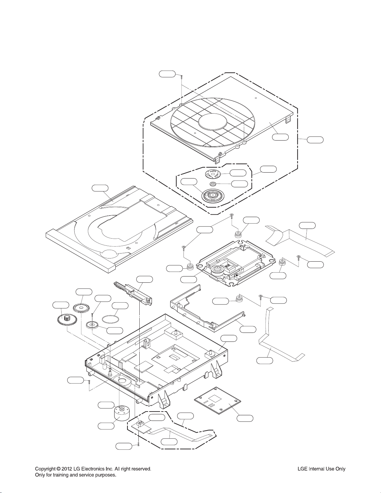
2. DECK MECHANISM SECTION, BM12H2 (LG08)
1439
1013
1017
1026
1433
1015
1012
1024
1003
1049
1437
1024
1005
1004
1025
1001
1002
1025
1437
A001
1030
1437
1431
1019
1018
1016
1439
1043
1045
A005
2-3
1011
1020
1031
1050
Page 15
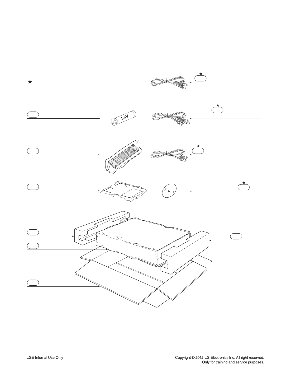
3. PACKING ACCESSORY SECTION
OPTIONAL PARTS
808 Battery
900 Remote Control
801 Instruction Ass’y
811 Plug Ass’y 1way (Black)
812 Plug Ass’y 2way
(Red/White)
814 Plug Ass’y 1way (Yellow)
832 Disc
803 Packing
804 Bag
802 Box
803 Packing
2-4
Page 16

SECTION 3 ELECTRICAL
CONTENTS
DIGITAL DISPLAY & MEDIA TRAINING MASTER ......................................................................... 3-2
ONE POINT REPAIR GUIDE ................................................................................................................. 3-68
1. NO POWER PROBLEM ....................................................................................................................... 3-68
2. VFD DOESN’T DISLPAY ...................................................................................................................... 3-69
3. NO BOOTING WHEN YOU TURN THE UNIT ON, “HELLO” OR “WAIT” ON FRONT PANEL ........... 3-70
4. NO HDD DETECTED ........................................................................................................................... 3-75
5. DISC TRAY CAN NOT OPEN, CLOSE/ DISC READING PROBLEM ................................................. 3-76
6. NO FLD DISPLAY/ NO REMOTE CONTROL ...................................................................................... 3-77
ELECTRICAL TROUBLESHOOTING GUIDE .................................................................................. 3-78
1. POWER SUPPLY ON SMPS BOARD .................................................................................................. 3-78
2. POWER SUPPLY ON MAIN BOARD ................................................................................................... 3-82
3. POWER ON .......................................................................................................................................... 3-86
4. SYSTEM PART ..................................................................................................................................... 3-87
5. NO CVBS VIDEO OUTPUT WHEN PLAY DISC .................................................................................. 3-89
6. NO COAXIAL OUTPUT WHEN PLAY DISC ........................................................................................ 3-90
7. NO ANALOG AUDIO L/R OUTPUT WHEN PLAY DISC ...................................................................... 3-91
8. NO HDMI OUTPUT WHEN PLAY DISC ............................................................................................... 3-92
9. NO DVB-T TUNER OUTPUT ................................................................................................................ 3-93
WAVEFORMS ............................................................................................................................................. 3-94
1. SYSTEM PART ..................................................................................................................................... 3-94
2. SYSTEM PART - MEMORY ................................................................................................................. 3-95
3. VIDEO PART (100% FULL COLOR BAR) ........................................................................................... 3-96
4. AUDIO PART - 1 (1 KHZ SINE WAVE) ................................................................................................ 3-97
5. AUDIO PART - 2 (1 KHZ SINE WAVE) ................................................................................................ 3-98
6. HDMI PART .......................................................................................................................................... 3-99
WIRING DIAGRAM.................................................................................................................................. 3-100
BLOCK DIAGRAMS ............................................................................................................................... 3-102
1. OVERALL BLOCK DIAGRAM ............................................................................................................ 3-102
2. SMPS BOARD BLOCK DIAGRAM ..................................................................................................... 3-103
3. MAIN BOARD - SYSTEM BLOCK DIAGRAM .................................................................................... 3-104
4. MAIN BOARD - INPUT/ OUTPUT BLOCK DIAGRAM ....................................................................... 3-105
5. MAIN BOARD - TUNER BLOCK DIAGRAM ...................................................................................... 3-106
6. FRONT TIMER BOARD BLOCK DIAGRAM....................................................................................... 3-107
7. MAIN BOARD POWER SIGNAL ........................................................................................................ 3-108
8. MAIN BOARD - SYSTEM & TUNER POWER SIGNAL ..................................................................... 3-109
9. MAIN BOARD - INPUT/ OUTPUT POWER SIGNAL ......................................................................... 3-110
10. FRONT TIMER BOARD POWER SIGNAL ......................................................................................... 3-111
CIRCUIT DIAGRAMS ............................................................................................................................. 3-113
1. SMPS CIRCUIT DIAGRAM ................................................................................................................ 3-113
2. MAIN - POWER CIRCUIT DIAGRAM ................................................................................................. 3-115
3. MAIN - MICOM CIRCUIT DIAGRAM .................................................................................................. 3-117
4. MAIN - BCM7632 #1 CIRCUIT DIAGRAM ......................................................................................... 3-119
5. MAIN - BCM7632 #2 CIRCUIT DIAGRAM ......................................................................................... 3-121
6. MAIN - DDR3 NAND CIRCUIT DIAGRAM ......................................................................................... 3-123
7. MAIN - FRONT END CIRCUIT DIAGRAM ......................................................................................... 3-125
8. MAIN - A/V OUTPUT CIRCUIT DIAGRAM ......................................................................................... 3-127
9. MAIN - USB HUB CIRCUIT DIAGRAM .............................................................................................. 3-129
10. MAIN - DVB-T TUNER/ 3D CIRCUIT DIAGRAM ............................................................................... 3-131
11. FRONT TIMER CIRCUIT DIAGRAM .................................................................................................. 3-133
CIRCUIT VOLTAGE CHART ............................................................................................................... 3-135
PRINTED CIRCUIT BOARD DIAGRAMS ........................................................................................ 3-137
1. MAIN P.C.BOARD .............................................................................................................................. 3-137
2. SMPS P.C.BOARD ............................................................................................................................. 3-141
3. FRONT TIMER P.C. BOARD .............................................................................................................. 3-143
3-1
Page 17
DIGITAL DISPLAY & MEDIA TRAINING MASTER
Objective: To provide clear and concise guidelines for customer service agents to handle calls on
box goods calls.
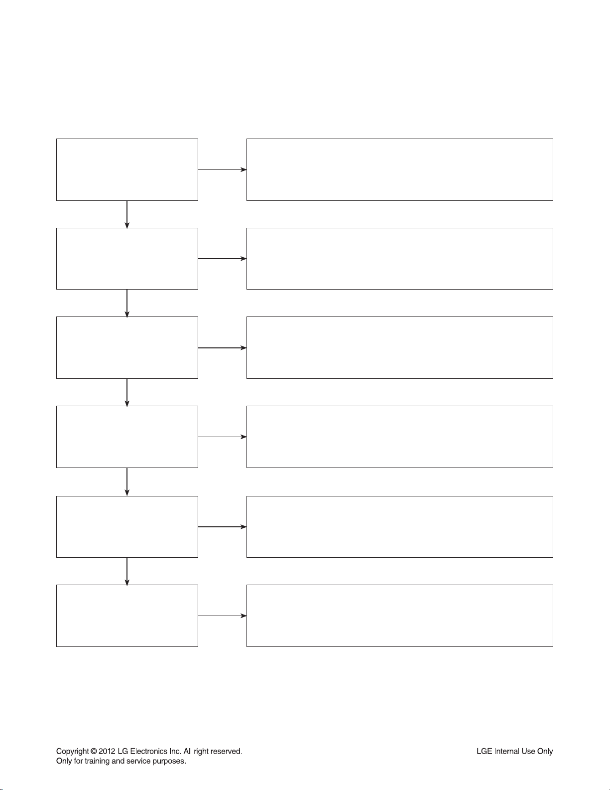
1. DISTORTED PICTURE
1-1. Lines on Picture
Distorted picture refers to the customer getting video, but there is a problem with the video.
Determine what cables the customer is using to connect
What cables is
the customer using to
connect the BD?
YES
NO
the BD to the TV and if connected properly. Refer to OM for
connections. Tighten any loose cables. Make sure the customer
is not connecting a BD to VCR or BD to DVD Recorder.
Copy protection can distort the picture on older DVD models.
Is the TV set
to the correct input?
YES
Do lines appear when
watching multiple discs?
YES
Do lines appear when
watching a TV program?
YES
Do lines appear
when the BD is
connected to another TV?
NO
NO
NO
NO
Make sure the TV is on the correct input.
Turn TV off, then on to determine input.
Video when using composite, or component.
DVI when using DVI, and HDMI when using HDMI.
One disc displaying the issue is a problem with the disc.
Multiple discs displaying the problem could indicate the BD lens
needs to be cleaned. Recommend the customer use a lens
cleaner on the BD. A lens cleaner is available at any local
electronics retailer.
Lines appearing when watching a TV program indicates
an issue with the display. If the TV program is fine,
then connect the BD to another input on the display to
determine if the problem is following the BD.
Connect the BD to another TV and play a disc.
No lines during disc play back indicates a problem with the first TV.
Please refer to the owners manual for instructions on how to
connect the BD to a TV. If the BD has a problem on the
second TV, then see service chart for service information.
YES
Has the customer tried
another set of cables?
NO
Have the customer try another set of cables. A bad cable can
also cause video problems. Test the cable with another device to
the TV to also determine if the TV is bad. If BD is problem,
please see service chart for service information.
3-2
Page 18

DIGITAL DISPLAY & MEDIA TRAINING MASTER
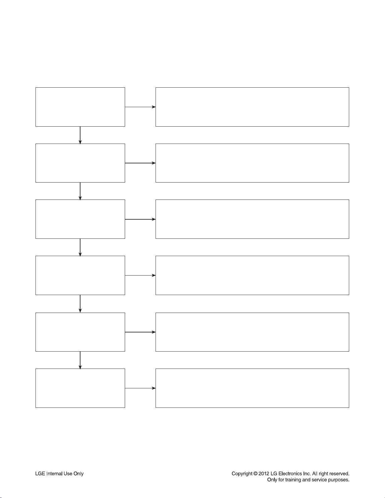
1-2. Ghost Picture
Distorted picture refers to the customer getting video, but there is a problem with the video.
Determine what cables the customer is using to connect the BD to
What cables is the customer
using to connect the BD?
YES
NO
the TV and if connected properly. Refer to OM for connections.
Tighten any loose cables. Make sure the customer is not connecting a
BD to VCR or BD to DVD Recorder. Copy protection can distort
the picture on older VCR models.
Is the TV set to
the correct input?
YES
Do ghosting appear when
watching multiple discs?
YES
Do lines appear when
watching a TV program?
YES
Does ghosting
appear when the BD is
connected to another TV?
NO
NO
NO
NO
Make sure the TV is on the correct input. Turn TV off,
then on to determine input. Video when using composite,
or component. DVI when using DVI, and HDMI when using HDMI.
One disc displaying the issue is a problem with the disc.
Multiple discs displaying the problem could indicate the BD lens
needs to be cleaned. Recommend the customer use a lens cleaner
on the BD. A lens cleaner is available at any local electronics retailer.
Ghosting appearing when watching a TV program indicates an
issue with the display. If the TV program is fine, then connect
the BD to another input on the display to determine
if the problem is following the BD.
Connect the BD to another TV and play a disc.
No ghosting during disc play back indicates a problem with the first TV.
Please refer to the owners manual for instructions on how to
connect the BD to a TV. If the BD has a problem on the second TV,
then see service chart for service information.
YES
Has the customer tried
another set of cables?
NO
Have the customer try another set of cables. A bad cable can
also cause video problems. Test the cable with another device to
the TV to also determine if the TV is bad. If BD is problem,
please see service chart for service information.
3-3
Page 19

DIGITAL DISPLAY & MEDIA TRAINING MASTER
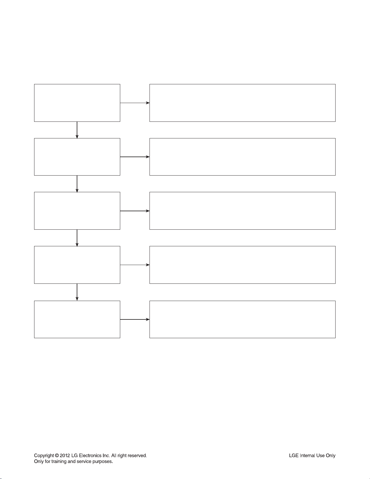
1-3. Rolling Picture
Distorted picture refers to the customer getting video, but there is a problem with the video.
Determine what cables the customer is using to connect the BD to
What cables is the customer
using to connect the BD?
YES
NO
the TV and if connected properly. Refer to OM for connections.
Tighten any loose cables. Make sure the customer is not connecting
a BD to VCR or BD to DVD Recorder. Copy protection can distort
the picture on older VCR models.
Is the TV set to
the correct input?
YES
Does rolling appear when
watching multiple discs?
YES
Does rolling appear when
watching a TV program?
YES
Does rolling appear
when the BD is connected to
another TV?
NO
NO
NO
NO
Make sure the TV is on the correct input. Turn TV off,
then on to determine input. Video when using composite,
or component. DVI when using DVI, and HDMI when using HDMI.
One disc displaying the issue is a problem with the disc.
Multiple discs displaying the problem could indicate the BD lens
needs to be cleaned. Recommend the customer use a lens cleaner
on the BD. A lens cleaner is available at any local electronics retailer.
Rolling appearing when watching a TV program indicates
an issue with the display. If the TV program is fine, then connect
the BD to another input on the display to determine if the problem
is following the BD.
Connect the BD to another TV and play a disc. No lines during disc play
back indicates a problem with the first TV. Please refer to the owners
manual for instructions on how to connect the BD to a TV. If the BD has a
problem on the second TV, then see service chart for service information.
YES
Has the customer tried
another set of cables?
NO
Have the customer try another set of cables. A bad cable can also
cause video problems. Test the cable with another device to the TV
to also determine if the TV is bad. If BD is problem,
please see service chart for service information.
3-4
Page 20
DIGITAL DISPLAY & MEDIA TRAINING MASTER
1-4. Shaky Picture
Distorted picture refers to the customer getting video, but there is a problem with the video.
Determine what cables the customer is using to connect the BD to
What cables is the customer
using to connect the BD?
YES
NO
the TV and if connected properly. Refer to OM for connections.
Tighten any loose cables. Make sure the customer is not connecting a
BD to VCR or BD to DVD Recorder. Copy protection can distort
the picture on older VCR models.
Is the TV set to
the correct input?
YES
Does shaking appear when
watching multiple discs?
YES
Does shaking appear when
watching a TV program?
YES
Does shaking appear
when the BD is connected to
another TV?
NO
NO
NO
NO
Make sure the TV is on the correct input. Turn TV off, then on
to determine input. Video when using composite, or component.
DVI when using DVI, and HDMI when using HDMI.
One disc displaying the issue is a problem with the disc.
Multiple discs displaying the problem could indicate the BD lens
needs to be cleaned. Recommend the customer use a lens cleaner
on the BD. A lens cleaner is available at any local electronics retailer.
Shaking appearing when watching a TV program indicates
n issue with the display. If the TV program is fine, then connect
the BD to another input on the display to determine if the problem
is following the BD.
Connect the BD to another TV and play a disc. No shaking during
disc play back indicates a problem with the first TV. Please refer to
the owners manual for instructions on how to connect the BD to a TV.
If the BD has a problem on the second TV,
then see service chart for service information.
YES
Has the customer tried
another set of cables?
NO
Have the customer try another set of cables. A bad cable can
also cause video problems. Test the cable with another device to
the TV to also determine if the TV is bad. If BD is problem,
please see service chart for service information.
3-5
Page 21
DIGITAL DISPLAY & MEDIA TRAINING MASTER
1-5. Blurry Picture
Distorted picture refers to the customer getting video, but there is a problem with the video.
Determine what cables the customer is using to connect the BD to
What cables is the customer
using to connect the BD?
YES
NO
the TV and if connected properly. Refer to OM for connections.
Tighten any loose cables. Make sure the customer is not connecting
a BD to VCR or BD to DVD Recorder. Copy protection can distort
the picture on older VCR models.
Is the TV set to
the correct input?
YES
Does blurriness appear when
watching multiple discs?
YES
Does blurriness appear when
watching a TV program?
YES
Does blurriness appear
when the BD is connected to
another TV?
NO
NO
NO
NO
Make sure the TV is on the correct input. Turn TV off,
then on to determine input. Video when using composite, or component.
DVI when using DVI, and HDMI when using HDMI.
One disc displaying the issue is a problem with the disc.
Multiple discs displaying the problem could indicate the BD lens
needs to be cleaned. Recommend the customer use a lens cleaner on
the BD. A lens cleaner is available at any local electronics retailer.
Blurriness appearing when watching a TV program indicates an
issue with the display. If the TV program is fine, then connect
the BD to another input on the display to determine if the problem
is following the BD.
Connect the BD to another TV and play a disc. No blurriness
during disc play back indicates a problem with the first TV.
Please refer to the owners manual for instructions on how to connect
the BD to a TV. If the BD has a problem on the second TV,
then see service chart for service information.
YES
Has the customer tried
another set of cables?
NO
Have the customer try another set of cables.
A bad cable can also cause video problems. Test the cable with another
device to the TV to also determine if the TV is bad. If BD is problem, please
see service chart for service information.
3-6
Page 22

DIGITAL DISPLAY & MEDIA TRAINING MASTER
2. NO PICTURE
2-1. Black Screen
The entire screen is black.
Does the BD on-screen
menu appear?
YES
What cables is the customer
using to connect the BD?
YES
Is the TV set to
the correct input?
YES
Is the customer able to
watch TV programming?
NO
NO
NO
NO
Make sure the customer did not select 480i resolution in the menu
of the BD player if using HDMI connections. Change resolution on
upconversion BD player by pushing the resolution button of the remote con-
troller. HDMI don’t support 480i resolution.
Determine what cables the customer is using to connect the BD to
the TV and if connected properly. Refer to OM for connections.
Tighten any loose cables. Make sure the customer is not connecting a
BD to VCR or BD to DVD Recorder. Copy protection can distort
the picture on older VCR models.
Make sure the TV is on the correct input. Turn TV off,
then on to determine input. Video when using composite, or component.
DVI when using DVI, and HDMI when using HDMI.
If the customer is not able to watch television then he may have a
problem with his television, especially if the cable signal comes
through on a different input. If the customer can not get a TV program,
then he still may have a problem with the particular input on his TV.
YES
Can the customer connect
the BD to another TV?
YES
Has the customer tried
another set of cables?
NO
NO
Have the customer connect the BD to another TV in order to
determine if the problem is the BD or the TV. Refer to the OM for
connections assistance. If the BD works on the second TV,
then the customer has a problem with his TV.
Have the customer try another set of cables. A bad cable can
also cause video problems. Test the cable with another device to the TV
to also determine if the TV is bad. If BD is problem, please see
service chart for service information.
3-7
Page 23

DIGITAL DISPLAY & MEDIA TRAINING MASTER
2-2. Blue Screen
The entire screen is a solid blue color.
Does the BD on-screen
menu appear?
YES
What cables is the customer
using to connect the BD?
YES
Is the TV set to
the correct input?
YES
Is the customer able to
watch TV programming?
NO
NO
NO
NO
Make sure the customer did not select 480i resolution in the menu
of the BD player if using HDMI connections. Change resolution on
upconversion BD player by pushing the resolution button of the remote con-
troller. HDMI don’t support 480i resolution.
Determine what cables the customer is using to connect the BD
to the TV and if connected properly. Refer to OM for connections.
Tighten any loose cables. Make sure the customer is not connecting a
BD to VCR or BD to DVD Recorder. Copy protection can distort
the picture on older VCR models.
Make sure the TV is on the correct input.
Turn TV off, then on to determine input. Video when using composite,
or component. DVI when using DVI, and HDMI when using HDMI.
If the customer is not able to watch television then he may have a
problem with his television, especially if the cable signal comes
through on a different input. If the customer can not get a TV program,
then he still may have a problem with the particular input on his TV.
YES
Can the customer connect
the BD to another TV?
YES
Has the customer tried
another set of cables?
NO
NO
Have the customer connect the BD to another TV in order to
determine if the problem is the BD or the TV. Refer to the OM for
connections assistance. If the BD works on the second TV,
then the customer has a problem with his TV.
Have the customer try another set of cables. A bad cable can also
cause video problems. Test the cable with another device to
the TV to also determine if the TV is bad. If BD is problem,
please see service chart for service information.
3-8
Page 24

DIGITAL DISPLAY & MEDIA TRAINING MASTER
2-3. Snowy Screen
A snowy picture is when black and white dots are all over the screen.
Does the BD on-screen
menu appear?
YES
What cables is the customer
using to connect the BD?
YES
Is the TV set to
the correct input?
YES
Is the customer able to
watch TV programming?
NO
NO
NO
NO
Make sure the customer did not select 480i resolution in the menu
of the BD player if using HDMI connections. Change resolution on
upconversion BD player by pushing the resolution button of the remote con-
troller. HDMI don’t support 480i resolution.
Determine what cables the customer is using to connect the BD
to the TV and if connected properly. Refer to OM for connections.
Tighten any loose cables. Make sure the customer is not connecting a
BD to VCR or BD to DVD Recorder. Copy protection can distort
the picture on older VCR models.
Make sure the TV is on the correct input. Turn TV off,
then on to determine input. Video when using composite, or component.
DVI when using DVI, and HDMI when using HDMI.
If the customer is not able to watch television then he may
have a problem with his television, especially if the cable signal comes
through on a different input. If the customer can not get a TV program,
then he still may have a problem with the particular input on his TV.
YES
Can the customer connect
the BD to another TV?
YES
Has the customer tried
another set of cables?
NO
NO
Have the customer connect the BD to another TV in order to
determine if the problem is the BD or the TV. Refer to the OM for
connections assistance. If the BD works on the second TV,
then the customer has a problem with his TV.
Have the customer try another set of cables. A bad cable can
also cause video problems. Test the cable with another device to
the TV to also determine if the TV is bad. If BD is problem,
please see service chart for service information.
3-9
Page 25

DIGITAL DISPLAY & MEDIA TRAINING MASTER
2-4. No Signal
A “no signal” message appears on the screen of the display.
Does the BD on-screen
menu appear?
YES
What cables is the customer
using to connect the BD?
YES
Is the TV set to the
correct input?
YES
Is the customer able to
watch TV programming?
NO
NO
NO
NO
Make sure the customer did not select 480i resolution in the
menu of the BD player if using HDMI connections. Change resolution on
upconversion BD player by pushing the resolution button of the remote con-
troller. HDMI don’t support 480i resolution.
Determine what cables the customer is using to connect the BD
to the TV and if connected properly. Refer to OM for connections.
Tighten any loose cables. Make sure the customer is not connecting a
BD to VCR or BD to DVD Recorder. Copy protection can distort
the picture on older VCR models.
Make sure the TV is on the correct input. Turn TV off,
then on to determine input. Video when using composite, or component.
DVI when using DVI, and HDMI when using HDMI.
If the customer is not able to watch television then he may have a
problem with his television, especially if the cable signal comes
through on a different input. If the customer can not get a TV program,
then he still may have a problem with the particular input on his TV.
YES
Can the customer connect
the BD to another TV?
YES
Has the customer tried
another set of cables?
NO
NO
Have the customer connect the BD to another TV in order to
determine if the problem is the BD or the TV. Refer to the OM for
connections assistance. If the BD works on the second TV,
then the customer has a problem with his TV.
Have the customer try another set of cables. A bad cable
can also cause video problems. Test the cable with another device to
the TV to also determine if the TV is bad. If BD is problem,
please see service chart for service information.
3-10
Page 26
DIGITAL DISPLAY & MEDIA TRAINING MASTER
2-5. Invalid Format or Format Not Supported
Make sure the customer’s simultaneously connecting analog component
Is the customer using a
digital cable connection?
YES
NO
cable with HDMI cable. And then If Copy Protected Disc is playing back,
analog component output is no picture. Only when the analog output
is 480i, you can see the picture. In case of No Copy Protected Disc,
you can see the picture regardless of the resolution.
Is the customer using an
analog cable connection?
YES
Is the display
HDCP compliant?
YES
Has the customer tried the
device on another display?
YES
Has the customer tried
another cable?
NO
NO
NO
NO
Customer’s using an DVI, or HDMI cable connection need to set
the resolution on the product above 480i. HDMI, DVI connections
can not process a 480i resolution. They can only process a 480p,
720p, 1080i, or 1080p resolution.
Make sure the display is HDCP compliant when using a DVI or
HDMI connection. A lack of HDCP compliancy on the display may
cause an invalid format or format not supported message to appear.
It can also cause a copy protection OSD to appear.
Ask the customer to connect the device to another display.
If the device starts working, then the problem may be the original display.
The customer will need to troubleshoot the display. If the device
still does not work, then the problem may be the device or the cable.
Ask the customer to replace the cable between the device and display.
If the problem is corrected, then the problem was with the cable.
If the problem continues, then the device is the problem.
Set up service according to in warranty or out of warranty procedures.
3-11
Page 27

DIGITAL DISPLAY & MEDIA TRAINING MASTER
3. PICTURE COLOR
3-1. No Color
The video displays no color and only shows in black and white.
What cables is the customer
using to connect the BD?
YES
Is the TV set to the
correct input?
YES
Does color appear when
watching multiple discs?
YES
Does color appear when
watching a TV program?
NO
NO
NO
NO
Determine what cables the customer is using to connect the BD
to the TV and if connected properly. Refer to OM for connections.
Tighten any loose cables. Make sure the customer is not connecting a
BD to VCR. Copy protection can distort the picture on older VCR models.
Make sure the TV is on the correct input according to the
connections in use. Video when using composite, or component.
DVI when using DVI, and HDMI when using HDMI.
One disc displaying the issue is a problem with the disc.
Make sure the discs the customer is using are compatible with the
BD by checking “playable discs” in the owners manual.
Multiple discs displaying the problem indicates a problem with
the BD player.
If the cable or satellite programming is connected through
another input and the customer does not get color, the customer has a
problem with his television. If a TV program does have the color,
the problem may be the BD player, the cables being used,
or the TV itself.
YES
Does color appear
when the BD is
connected to another TV?
YES
Has the customer tried
another set of cables?
NO
NO
Connect the BD to another TV and play a disc. Good color during
disc play back indicates a problem with the first TV. Please refer to the
owners manual for instructions on how to connect the BD to a TV.
If the BD has a problem on the second TV, then see service chart for
service information.
Have the customer try another set of cables. A bad cable can
also cause video problems. Test the cable with another device to
the TV to also determine if the TV is bad. If the BD is the problem,
please see service chart for service information.
3-12
Page 28

DIGITAL DISPLAY & MEDIA TRAINING MASTER
3-2. Poor Color
The color is poor. Examples would be washed out colors, colors bleeding into one another, or a solid tint to
a screen.
What cables is the customer
using to connect the BD?
YES
Is the TV set to the
correct input?
YES
Is color fine when watching
multiple discs?
YES
Is color fine when watching
a TV program?
NO
NO
NO
NO
Determine what cables the customer is using to connect the BD to
the TV and if connected properly. Refer to OM for connections.
Tighten any loose cables. Make sure the customer is not connecting a
BD to VCR. Copy protection can distort the picture on older VCR models.
Make sure the TV is on the correct input according to the
connections in use. Video when using composite, or component.
DVI when using DVI, and HDMI when using HDMI.
One disc displaying the issue is a problem with the disc.
Make sure the discs the customer is using are compatible with the BD
by checking “playable discs” in the owners manual. Multiple discs
displaying the problem indicates a problem with the BD player.
If the cable or satellite programming is connected through another
input and the customer does not get color, the customer has a problem with
his television. If a TV program does have the color, the problem
may be the BD player, the cables being used, or the TV itself.
YES
Is color fine when the BD is
connected to another TV?
YES
Has the customer tried
another set of cables?
NO
NO
Connect the BD to another TV and play a disc. Good color during
disc play back indicates a problem with the first TV. Please refer to the
owners manual for instructions on how to connect the BD to a TV.
If the BD has a problem on the second TV, then see service
chart for service information.
Have the customer try another set of cables. A bad cable
can also cause video problems. Test the cable with another device to
the TV to also determine if the TV is bad. If the BD is the problem,
please see service chart for service information.
3-13
Page 29

DIGITAL DISPLAY & MEDIA TRAINING MASTER
4. NOISE/AUDIO PROBLEMS
4-1. No Audio
The customer is not able to get audio.
What cables is the customer
using to connect the BD?
YES
NO
Determine what cables the customer is using to connect the BD
to the TV and if connected properly. Refer to OM for connections.
Tighten any loose cables. Make sure the customer has audio cables
connected if using an HDMI to DVI adapter or video-only cables
(DVI, component, etc).
Is the customer
able to see video?
YES
Does issue occur on
more than one disc?
YES
Problem occur when
watching TV program?
YES
Does the problem occur
when BD is connected to
another TV?
NO
NO
NO
NO
Make sure the customer has not routed video
and audio to separate inputs.
Problem occurring on one disc indicates a problem with the disc.
Problem occurring on multiple discs could indicate a lens cleaner
is needed. The customer can purchase a lens cleaner at any
electronics retailer.
No audio from a TV program on a different channel or input means
there is a problem with the television. If a TV program does have
the audio, the problem may be the BD player, the cables being used,
or the TV itself.
Audio is fine when the BD is connected to another TV
indicates the problem is with the television. Refer to
the owners manual for assistance with connecting BD to another TV.
YES
Has the customer tried
another set of cables?
NO
Have the customer try another set of cables. A bad cable can also
cause audio problems. Test the cable with another device to
the TV to also determine if the TV is bad. If BD is problem,
please see service chart for service information.
3-14
Page 30

DIGITAL DISPLAY & MEDIA TRAINING MASTER
4-2. Distorted Audio
The audio sounds muffled, scratchy, or the audio skips.
Determine what cables the customer is using to connect the BD
What cables is the customer
using to connect the DVD?
YES
NO
to the TV and if connected properly. Refer to OM for connections.
Tighten any loose cables. Make sure the customer has audio
cables connected if using an HDMI to DVI adapter or video-only cables
(DVI, component, etc).
Is the customer
able to see video?
YES
Does issue occur on
more than one disc?
YES
Problem occur when
watching TV program?
YES
Does the problem occur
when DVD is connected to
another TV?
NO
NO
NO
NO
Make sure the customer has not routed
video and audio to separate inputs.
Problem occurring on one disc indicates a problem with the disc.
Problem occurring on multiple discs could indicate a lens cleaner
is needed. The customer can purchase a lens cleaner at any
electronics retailer.
Distorted audio from a TV program on a different channel or
input means there is a problem with the television. If a TV program
does have the audio, the problem may be the BD player, the cables
being used, or the TV itself.
Audio is fine when the BD is connected to another TV
indicates the problem is with the television. Refer to the owners manual
for assistance with connecting BD to another TV.
YES
Has the customer tried
another set of cables?
NO
Have the customer try another set of cables. A bad cable can
also cause audio problems. Test the cable with another device to
the TV to also determine if the TV is bad. If BD is problem,
please see service chart for service information.
3-15
Page 31

DIGITAL DISPLAY & MEDIA TRAINING MASTER
4-3. Humming/Clicking Noise
The unit is making a humming noise or a clicking noise.
Does the noise only
happen when a disc
is playing?
YES
NO
A clicking noise or a noise interfering with audio may indicate a problem.
Try multiple discs. Multiple discs with the same issue means the
BD may need service or be professionally cleaned.
BDs make a slight hum when playing discs.
Check BD service for service instructions.
Check to see if a disc is inserted into the BD and eject the disc.
A humming or clicking noise when the disc is not inserted
may be a cooling fan. Check OM to see if cooling fan is present.
If not, unit will need service. See BD service for service instructions.
Does the noise happen
when the BD is turned on?
NO
4-4. Audio/Video Out of Synch
The audio and video do not match up. People look to be talking, but their voices are delayed by a few seconds.
If the issue only shows up on one disc, then the problem is
with that disc. Have the customer try multiple tapes or discs.
If the issue happens on multiple discs and tapes,
then ask the customer to try a lens or a head cleaner.
Make sure cables are routed properly.
Make sure audio and video cables are routed to the same source
(if possible). Routed audio and video to separate products
can cause a bit of a delay between the devices as not all devices
will process audio and video signals at the same speed.
Has the customer tried
multiple tapes and discs?
YES
How are the cables routed?
YES
NO
NO
Has the customer
connected to another TV?
NO
Ask the customer to connect the product to another TV.
If the issue persists, try another set of cables. If the issue still persists,
then the issue is with the unit. The unit will need service.
Arrange service following proper procedure.
3-16
Page 32

DIGITAL DISPLAY & MEDIA TRAINING MASTER
5. MISCELLANEOUS
5-1. No Power
The unit will not turn on.
Is the unit plugged in?
YES
Does the unit turn on
when the power button
is pressed on the unit?
YES
Is the unit plugged into
a surge protector?
YES
Does the unit work when
plugged into another outlet?
YES
NO
NO
NO
NO
Make sure the unit is plugged into a surge protector or the wall.
See if the unit will turn on when the power button the unit is pressed.
If the unit turns on, then troubleshoot the remote control using
the Remote Control Not Working call flow.
Make sure the surge protector is plugged into a wall outlet.
Also make sure the surge protector is turned on or does not
need to be reset due to a recent surge.
Test the unit in another outlet. If the unit works,
then the problem is the outlet where the unit was connected.
If the issue is the BD, then set up service for BD according to
BD service guide.
Have there been any lightning
strikes or power outages?
NO
If BD failed due to lightning strike or a power surge,
this is not covered by warranty. Follow guidelines
for service for a BD out of warranty.
3-17
LGE Internal Use Only
Page 33

DIGITAL DISPLAY & MEDIA TRAINING MASTER
5-2. Disc Error
The unit displays “disc error” when a disc is inserted into the BD player.
Is the disc inserted into
the BD player properly?
YES
What type of disc is
the customer using?
YES
Did the customer burn
this disc in a DVD recorder?
YES
Did the customer burn
the disc in a computer?
NO
NO
NO
NO
Make sure the disc has been inserted into the BD player properly.
The player can not read a disc inserted into the unit upside down.
Determine the type of disc the customer is not able to play.
If the customer is using a store-bought movie BD,
then please skip the next three questions.
If it’s a recorded disc, move onto the next question.
Make sure the customer finalized the disc in the DVD recorder.
Make sure the type of disc the customer is using is compatible
with the BD player. If the customer initialized a DVD-RW in VR mode,
make sure the owners manual has the RW logo to show
compatibility for the VR format.
Make sure the customer burned a compatible format
(such as VCD, SVCD, or DivX). Make sure the file meets the
specifications required for the player to play the disc. Check the owners
manual for specifications. Disc may still not be compatible.
Refer customer to section of OM regarding burned discs.
YES
Has the customer tried
multiple discs?
NO
One disc with the problem is a problem with the disc.
BD players can play scratched or dirty BDs (DVDs) and not have any
issues during playback. Multiple discs with the issue can mean
the lens on the BD player needs to be cleaned. Recommend a
lens cleaner. Service BD if lens cleaner was used.
3-18
Page 34

DIGITAL DISPLAY & MEDIA TRAINING MASTER
5-3. Unit Locks Up
Unit does not respond to any commands.
Does the unit respond to
the buttons on the unit?
YES
Has the customer
reset the unit?
5-4. Disc Stuck
A BD disc is stuck in the unit.
Does the open/close button
on the unit work?
YES
NO
NO
NO
If the unit will turn on or off with the button on the unit,
troubleshoot the remote control. Please refer to
Remote Control Not Working call flow.
If the unit does no respond to any buttons,
then reset the unit by unplugging it for 15 to 30 seconds.
If the unit does not respond after the reset,
arrange for service on the BD.
Press the open/close button on the unit. If the disc ejects,
troubleshoot the remote using the Remote Control
not working call flow.
Has the customer reset the
unit?
NO
Ask the customer to reset the unit by unplugging the unit
from the electrical outlet for 15 to 30 seconds. If the disc
remains stuck in the unit after the reset, the unit will need service.
3-19
Page 35

DIGITAL DISPLAY & MEDIA TRAINING MASTER
5-5. Remote Control Not Working
Does the unit respond to
buttons on the front of the unit?
YES
Does the remote control
any component?
YES
Have the batteries
been changed?
YES
Is the remote working at all?
NO
NO
NO
NO
If the buttons on the front of the unit do not respond,
determine if the product has locked up or if the unit will not turn on.
The problem is not the remote control. Make sure the remote control is
the remote that goes with that particular model.
Determine which product the remote is not working.
The customer may need to press the appropriate mode button
to make the remote operate another component. The remote may
even need to be programmed to the other component,
especially if the batteries were just changed.
Ask the customer to change batteries.
Make sure the batteries are new and fresh.
The batteries do not need to come from a “spare” battery drawer.
Do not mix used and new batteries.
If the remote does not work anything, then walk the customer
through a remote drain. Remove the batteries from the remote control.
Then press and hold any button down for a minute.
This will drain the power out of the remote and reset it.
Universal remotes will have to be reprogrammed.
YES
Does any remote
work the unit?
YES
Does the customer want to
program their remote?
NO
NO
If another remote works the unit, then follow
the procedure to FOC the customer a new remote.
If two remotes do not work the unit, the unit will need service.
Please refer to the OM for instructions on how to
program remote to TV. Customer wants to program a remote
other than Zenith or LG, the customer will need to contact
the manufacturer of the remote control. Codes do not work,
remote is not compatible.
3-20
Page 36

DIGITAL DISPLAY & MEDIA TRAINING MASTER
5-6. Will Not Play Disc
The unit will not play a disc when a disc is inserted into the player.
Is the disc inserted into
the BD player properly?
YES
What type of disc is
the customer using?
YES
Did the customer burn this
disc in a DVD recorder?
YES
Did the customer burn
the disc in a computer?
NO
NO
NO
NO
Make sure the disc has been inserted into the BD player properly.
The player can not read a disc inserted into the unit upside down.
Determine the type of disc the customer is not able to play.
If the customer is using a store-bought BD, then please skip the
next three questions. If it’s a recorded disc,
move onto the next question.
Make sure the customer finalized the disc in the DVD recorder.
Make sure the type of disc the customer is using is compatible
with the BD player. If the customer initialized a DVD-RW in VR mode,
make sure the owners manual has the RW logo to show
compatibility for the VR format.
Make sure the customer burned a compatible format
(such as VCD, SVCD, or DivX). Make sure the file meets the
specifications required for the player to play the disc.
Check the owners manual for specifications. Disc may still not be
compatible. Refer customer to section of OM regarding burned discs.
YES
Has the customer tried
multiple discs?
NO
One disc with the problem is a problem with the disc.
BD players can play scratched or dirty BDs (DVDs) and not have
any issues during playback. Multiple discs with the issue can mean
the lens on the BD player needs to be cleaned.
Recommend a lens cleaner. Service BD if lens cleaner was used.
3-21
Page 37

DIGITAL DISPLAY & MEDIA TRAINING MASTER
5-7. Disc Freezes or Skips
The audio and video freeze and skip during play back of a BD or DVD disc.
Is the disc inserted into
the BD player properly?
YES
What type of disc is
the customer using?
YES
Did the customer burn this
disc in a DVD recorder?
YES
Did the customer burn
the disc in a computer?
NO
NO
NO
NO
Make sure the disc has been inserted into the BD player properly.
The player can not read a disc inserted into the unit upside down.
Determine the type of disc the customer is not able to play.
If the customer is using a store-bought BD,
then please skip the next three questions. If it’s a recorded disc,
move onto the next question.
Make sure the customer finalized the disc in the DVD recorder.
Make sure the type of disc the customer is using is compatible
with the BD player. If the customer initialized a DVD-RW in VR mode,
make sure the owners manual has the RW logo to show
compatibility for the VR format.
Make sure the customer burned a compatible format
(such as VCD, SVCD, or DivX). Make sure the file meets the
specifications required for the player to play the disc. Check the owners
manual for specifications. Disc may still not be compatible.
Refer customer to section of OM regarding burned discs.
YES
Has the customer tried
multiple discs?
NO
One disc with the problem is a problem with the disc.
BD players can play scratched or dirty BDs (DVDs) and not have
any issues during playback. Multiple discs with the issue can mean
the lens on the BD player needs to be cleaned. Recommend
a lens cleaner. Service BD if lens cleaner was used.
3-22
Page 38

DIGITAL DISPLAY & MEDIA TRAINING MASTER
5-8. Can Access Menu, but Not Play a Movie
The disc menu is displayed but the disc will not play.
Go into the system information screen of the BD player.
Check the system information
screen of the BD player.
YES
NO
To access this menu, bring up the main menu. Go to TV aspect,
highlight 16:9, press 1397139 and hit enter. If sold in the US,
this should be DVD region code 1 and BD region code A.
In case of HD-DVD, there is no region code.
What is the region code of
the BD disc?
NO
If the region code of the BD disc is not A, then the BD disc
will not play on a player sold in the US. The player can play only
BD discs labeled same as the rear of the unit.
YES
What is the region code of
the DVD disc?
NO
If the region code of the DVD disc is not 1, then the DVD disc
will not play on a player sold in the US. The player can play only
DVD discs labeled same as the rear of the unit.
YES
The disc locking up on a feature needs to be reported to Q&E.
Is the disc locking up on a
disclaimer screen when the
customer presses play?
NO
See instructions on reporting problems to Q&E. For a work
around the problem, advise the customer to access the chapter list.
Start play back from chapter 1 to start the movie and avoid any
5-9. Reporting a problem to Quality & Engineering
Reporting a problem that may require a firmware update to fix.
feature lock ups.
How do I report a problem to
Quality and Engineering?
NO
Get the micom version from the system information screen.
Get the ISBN number from the back of the BD box cover
(the number under the barcode). Get the exact problem
the customer is describing Email this information to Matt Wedgman
so the issue can be reported to the factory.
3-23
Page 39

DIGITAL DISPLAY & MEDIA TRAINING MASTER
5-10. Aspect Ratio
The customer has bars on the top and bottom of the screen, the left and right of the screen, or both.
Is the movie
wide screen or
full screen?
YES
What is the aspect
ratio of the DVD disc
being played?
YES
What is the aspect
ratio of the BD player
set at?
YES
What is the resolution
of the BD player set at?
NO
NO
NO
NO
A full screen movie played on a wide screen TV will have bars
on the left and right side of the TV. The customer needs to
make sure they choose the appropriate type of movie
they want to view.
If the aspect ratio is 1.33:1 then the movie is set up for full screen
viewing. Bars will appear on the left and right side of the screen
if the TV is wide screen. If the aspect ratio is 1.85:1 or 2.35:1,
then there will be bars on the top and bottom as that ratio is
bigger than widescreen TVs (1.78:1).
Make sure the BD player aspect ratio is set to
the appropriate setting, depending on the aspect ratio of the TV.
If the customer chose 4:3 Letterbox, then bars will appear on the top
and bottom. The customer can choose the panscan setting to
get rid of the bars.
Try changing the resolution to 480p. 720p, 1080i and
1080p resolution require a widescreen aspect ratio which
means bars will be placed on the left and right side for
full screen movies.
YES
What is the aspect ratio of
the television set at?
NO
Make sure the aspect of the television is set appropriately.
If the aspect ratio of the television is set at 4:3 when the TV
is wide screen, then a wide screen movie will show up as
letterbox with bars on the top and bottom and bars on the sides.
3-24
Page 40

DIGITAL DISPLAY & MEDIA TRAINING MASTER
5-11. My Unit Won’t Upconvert
The customer has a problem with getting the unit to change resolutions to 480p, 720p, 1080i, or 1080p.
Is the disc
currently playing?
YES
Is the customer using
component (red, blue,
and green) cables?
YES
Is the customer using
any sort of adapter cable?
YES
Is the customer using
an HDMI or DVI cable?
NO
NO
NO
NO
Ask the customer to press stop to stop the disc from playing.
Ask the customer to press the resolution button to change the resolution.
The BD player will not change resolutions while the disc is playing.
Discs with copy protection will not upconvert above 480p
when using component cables. The component output does not have
HDCP (highbandwidth digital content protection) compliancy
which causes the BD player to switch from 720p or 1080i to 480p.
RGB to DVI or RGB to HDMI adapters will not upconvert.
RGB outputs and inputs are not HDCP compliant. If the customer
sees an error message about HDCP, this is the issue.
Copy protected discs will not upconvert
when HDCP is not found on the input or output.
Regular discs can convert to 1080p over the HDMI output and
only the HDMI output. The TV has to have HDCP compliancy on
the HDMI input. The display has to accept the resolution
(480p, 720p, 1080i, or 1080p).
YES
Is the customer using an
HDMI to DVI cable?
YES
Has the customer tried
multiple discs?
NO
NO
Some movie companies will not allow their discs to upconvert
past 480p. If only one disc poses a problem, then the issue is the disc.
The customer will need to try multiple discs.
One disc not upconverting means the disc may not upconvert.
Some movie companies will not allow their discs to upconvert.
If multiple discs display the issue, remove the disc and change
the resolution with no disc in the unit.
If resolution will not change, the unit needs service.
3-25
Page 41

DIGITAL DISPLAY & MEDIA TRAINING MASTER
6. BLU-RAY PLAYER
6-1. Slow Loading Times for BDs
Why does it take so
long to load my BDs?
6-2. Booting Times
Why does it take
so long to boot my BD?
6-3. Ethernet Port
What is the purpose of
the ethernet port on
the BD Player?
NO
NO
NO
The loading times for a blu-ray disc is 30 seconds.
When a customer switches from one disc to another, the lens
will change which is what causes the delay.
Blu Ray require different lasers to read the discs.
The booting times for the BD is 20 seconds.
When the set is booted, it takes a little long time
to loading the OS program.
This is used for the unit to access a network dealing with interactive
BD movie menu. BD Player can support BD2.0 so that network
function is active in the BD disc. Also, BD Player can support VOD service
such as Netflix. (USA only)
Why is not the item
downloaded through the
network?
NO
6-4. Firmware Update Availability
Is there a firmware update
available for the BD Player?
NO
Make sure the customer insert the LAN cable into the Ethernet jack.
Make sure the network is active. If it is active,
the disc may have a problem.
If not active, see the network section of OM.
Yes, firmware updates are available at http://us.lgservice.com
that address some playback issues with movies.
Go to device drivers and click on DVD&VIDEO&SET-TOP.
The firmware updates are available there.
Advise the customer to download the firmware and unzip the file.
Also, firmware updates are done by network.
Select Home Menu -> Setup -> Others -> Software update menu.
3-26
Page 42

DIGITAL DISPLAY & MEDIA TRAINING MASTER
7. NETFLIX
7-1. Network Setup
(By connecting the unit to broadband Internet, you can use Netflix function)
Check the Network
Connection
YES
Configuration Network
Settings
YES
Checking Network
Configuration
NO
NO
NO
Connect the player’s LAN port to the corresponding port on your Modem
Router using a LAN cable. Use a commercially available straight LAN cable
(Category 5/CAT5 or better with RJ45 connector)
If there is a DHCP (Dynamic Host Configuration Protocol) server on the
local area network (LAN), this player will automatically be allocated an IP
address. If there is no DHCP server on the network and you want to set the
IP address manually, select [Static IP] then set the [IP Address], [Subnet
Mask], [Gateway] and [DNS Server] using [IP Setting] option
Select [NETWORK] on the [Setup] menu. And then Select [IP Mode] option
on the [NETWORK] menu. And then Check the Network status indicator
changes according to Network configuration.
3-27
Page 43

DIGITAL DISPLAY & MEDIA TRAINING MASTER
7-2. Activation
Activating the unit establishes a connection between the unit and Netflix account
Netflix member?
YES
Entering the activation code
YES
“Congratulations”
screen appears?
NO
NO
NO
Visit www.netflix.com/LG for your free trial.
After finishing to join the Netflix, select the [activate]
then press ENTER
Wait for the activation screen to appear on your TV screen.
On your computer, visit www.netflix.com/activate If necessary,
enter your Sign in Name and Password to log into your account.
Enter the activation code that appears on your TV screen.
Select [get an new code] for retry, Enter the activation
code again on the activation site www.netflix.com/activate
7-3. Adding Movie to your player
Instant Queue is not empty?
YES
Instant Queue titles <
500 titles
NO
show you want to watch, point your cursor at the [Add/Play] button to reveal
NO
Visit the Netflix website www.netflix.com on your computer.
If necessary, enter your Sign in Name and Password to log into your
account. Click [Watch Instantly] tab. When you find a movie or
additional options, and then click [Add to Instant Queue].
You can add up to 500 titles to your instant Queue,
however, we recommend adding 50 or less movies,
so that can easily find what you want to watch.
3-28
Page 44

DIGITAL DISPLAY & MEDIA TRAINING MASTER
7-4. ESN (Electronic Serial Number) Validation
(Select [OTHERS] on the [Setup] menu.
And then Select [Netflix] on the [OTHERS] menu.
And then Check [Netflix ESN].)
Does it begin with
“LGE-XXXXX-” followed by
“8-digit” ?
Example )
BD572 : LGE-BD572BD592 : LGE-BD592BD561 : LGE-BD561HB905 : LGE-HB905HB965 : LGE-HB965-
NO
If not, the set has a bad ESN (It should not happen) -> replace the player
YES
Select [Streaming] on the [Home] menu.
Is it activated successfully?
YES
Is Netflix server ok?
YES
Netflix server is ok,
but fails in activation.
NO
NO
NO
This means that ESN is valid.
If Netflix Server is dead,
activation fails
even if the ESN is valid.
Call Netflix Customer Support
and check that this ESN
added to the Netflix DB
3-29
Page 45

DIGITAL DISPLAY & MEDIA TRAINING MASTER
7-5. Less Bandwidth and less resolution movie than expected
The Quality indicator during movie retrieval corresponds to the following bandwidth requirements:
• 1.0 Mbps
• 1.5 Mbps
• 2.6 Mbps
• Best quality is 3.8 Mbps
Do you have adequate
broadband connection speed
YES
Do not have any other online
activity on your network
YES
Test your bandwidth
NO
NO
NO
We recommend a minimum connection speed of 1.5Mbps.
For the best quality picture, a connection speed of 4.0Mbps is required.
Your connection may be affected by other activity on your network,
such as online gaming, file sharing or other video streaming.
You can test your bandwidth at one of these sites:
http://www.speakeasy.net/speedtest/
http://www.speedtest.net/ If you are getting less bandwidth
than expected, you should contact your ISP to troubleshoot.
3-30
Page 46

DIGITAL DISPLAY & MEDIA TRAINING MASTER
7-6. Errors from Netflix server
Following operations could be abnormal if Netflix server is dead
• Activation
• Queue retrieving
• Movie playback
• Category list
Is it activated successfully?
YES
Does it fail to retrieve queue
data? (Title List)
YES
It retrieves queue data,
but fails to playback.
YES
If playback is ok, then move to
category list and choose one.
NO
NO
NO
NO
If Netflix NCCP server is dead, it fails in activating even if ESN is valid,
Network is setup correctly but it fails in retrieving the queue list,
then the Netflix NCCP server is dead.
Netflix NCCP server is alive, but Netflix streaming server is dead.
Netflix NCCP server/ Streaming server
is alive, but Web API server is dead.
3-31
Page 47

DIGITAL DISPLAY & MEDIA TRAINING MASTER
8. YouTube
8-1.Frequent buffering happens while playing videos.
Network Condition Meter indicate current network speed between
BD Player and YouTube stream server.
To play videos without buffering, Network Condition Meter should
have more than 3 Bars.
Do you have adequate broadband
connection speed?
YES
Do not have any Other online
activity on your network?
YES
Test your bandwidth
NO
NO
NO
We recommend a minimum connection speed of 1.5Mbps. For the best
quality picture, a connection speed of 4.0Mbps is required.
Your connection may be affected by other activity on your network, such as
online gaming, file sharing or other video streaming.
You can test your bandwidth at one of these sites:
http://www.speakeasy.net/speedtest/http://www.speedtest.net/
If you are getting less bandwidth than expected, you should contact your
ISP to troubleshoot.
3-32
Page 48

DIGITAL DISPLAY & MEDIA TRAINING MASTER
9. CINEMANOW
9-1. Entering the Cienmanow Function.
(Before using the Cinemanow function, it guides a user network status)
Does It connect to internet?
Check the network speed?
NO
NO
To enter cinemanow mode, it try to check internet connection.
If failed, it displays the popup message to the user.
User can move to [Home] menu or [Network setting] menu
as our guideline.
If success, it check the network speed from cinemanow server.
We recommend a minimum connection speed of 700kbps for playing titles.
If the result of speed check is lower than 700kbps, it displays the warning
message to user.
3-33
Page 49

DIGITAL DISPLAY & MEDIA TRAINING MASTER
9-2. Activation
(To rent or buy titles, a user must activate the player,
Activating the unit establishes a connection between the unit and Cinemanow
account)
Request activation code
Entering the activation code
NO
NO
Visit www.cinemanow.com/activate
If you are not member of cinemanow,
press “Get started” button to join the cinemanow.
if you are member, sign in.
Step 2
To get the activation code, move to bottom of this page
and press “Continue”
A user could change his information though this page.
(Payment Information, Adult Access Restrictions)
Step 3
You can see the 5 digite code.
This code only used onetime and is valid within 24 hours.
If success,
“Success, Your CinemaNow-ready device is now activated.” is displayed.
3-34
Page 50

DIGITAL DISPLAY & MEDIA TRAINING MASTER
9-3. Purchase titles
(To watch the stream video, you should browse and buy titles at the player.)
Select the title that you want
YES
Check the user billing info
YES
Check the title already
purchased
YES
Place order
NO
NO
NO
NO
To rent a title is more cheaper than buy,
but it only available 24 hour period, starting from the first time
they are played.
It checks the user billing information and balance.
If it is absent, Technical error occurs.
If a user purchased the titles,
It display the alarm message on the screen.
It is not count that rental expired titles.
If a user have an enough balance, it is applied automatically.
3-35
Page 51

DIGITAL DISPLAY & MEDIA TRAINING MASTER
9-4. Less Bandwidth and less resolution movie than expected
The Quality indicator during movie retrieval corresponds to the following bandwidth requirements:
• 1 box is 0.7 Mbps
• 2 boxs is 1.0 Mbps
• 3 boxs is 1.5 Mbps
• 4 boxs is 2.0 Mbps
Do you have adequate broadband
connection speed
YES
Do not have any Other online
activity on your network
YES
Test your bandwidth
9-5. Play title restriction.
NO
NO
NO
We recommend a minimum connection speed of 0.7Mbps.
If you have not enough speed, the unit displays proper message.
Your connection may be affected by other activity
on your network,
such as online gaming, file sharing or other video streaming.
You can test your bandwidth at one of these sites:
http://www.speakeasy.net/speedtest/http://www.speedtest.net/
If you are getting less bandwidth than expected, you should contact your
ISP to troubleshoot.
A title can be played
with one user id simultaneously.
A user meet an error code,
when he try to playback.
NO
NO
When a user try to play this stream that is already streaming on another
device, the unit displays error message.
It will be supported by Cinemanow with that error code.
It is not covered by LGE.
3-36
Page 52

DIGITAL DISPLAY & MEDIA TRAINING MASTER
9-6. Check your internet connection
Before starting cinemanow service,
it is checked whether internet is connected or not,
but during the network communication,
it is detected that internet connection is closed.
# Check Internet Access
A user make it sure that internet connection is working.
Please make sure your internet connection is working properly,
9-7. Cannot connect to CinemaNow Server.
Cannot connect to the internet.
and that your device is setup properly
Even though there is no problem at our
internet connection,
but we still fail to connect Cinemanow Server.
It will be solved by Cinemanow.
9-8. TimeOut
It happens that server response does not
finished within 30 seconds. However there
is no error at internet connection and
cinemanow server. It is due to network
congestion, so a user can retry it just a
few minute later.
Still a user have problem,
Check internet speed with this url
http://www.speakeasy.net/speedtest/
http://www.speedtest.net/
Andmore, to improvement, contact your ISP.
# Cinemanow Support
CinemaNow has encountered a Technical problem.
Please retry. If the problem persists, please contact CinemaNow
customer support at www.cinemanow.com/support
(Cannot connect to CinemaNow Server)
# Network Congestion
Cannot connect to CinemaNow service at this time.
Please try again in a few moments.
3-37
Page 53

DIGITAL DISPLAY & MEDIA TRAINING MASTER
9-9. CinemaNow Support
It occurs all our application runs well,
but it received unexpected result from
cinemanow server.
In this case,we print error code from
cinemanow server,
a user can serve from cinemanow
support pages,
www.cinemanow.com/help.
This can not be handled by LGE.
9-10. Other Network Error
If your internet environment is not enough
to serve Cinemanow feature,
Our application uses TCP/IP network
connection, with these port 80(HTTP),
443(SSL) and NTP(123).
One of these service is blocked, we can’t
support our service.
A user can consult ISP or IT manager.
Still you have a problem,
LG examine it for the detail reason.
# Cinemanow Support
CinemaNow has encountered a Technical problem.
Please retry. If the problem persists, please contact CinemaNow
customer support at www.cinemanow.com/support
(code [insert error code # here])
# Connectivity Problem
There is a problem with your connection.
Please make sure your internet connection is working properly.
3-38
Page 54

DIGITAL DISPLAY & MEDIA TRAINING MASTER
10. HOME LINK
10-1. What is Home link?
Home link is a Media File Sharing Function. User can play most of media fi les in my PC or my NAS ( Network Attached
Storage ). General DLNA compatible server shares Media Files on local network.
To connect DLNA server, user must have PC with DLNA server program or NAS with DLNA server certifi ed.
LG gives Home link bundle SW disc(PC DLNA Program for Windows).
Another way is to use just fi le sharing method, this is based on the standard of CIFS (Common Internet File System).
User don’t need any program, just set folder sharing on your PC.
Home link server search menu can search user-shared folders.
Home link support this media:
JPG,PNG,MP3,WMA,PCM,MPEG1,2,DivX(subtitle support),XviD,MKV,MP4
Other DLNA Servers:
Nero Media home, Cyberlink server, Twonky, Window Media Player11, QNAP NAS etc.
Restrictions:
1. PC and BD Player must be connected in one access point.
2. Anti-Virus program may block media sharing. Before installing SW, stop the Anti-Virus program.
3. LG bundle disc program is Essential program supported by Nero.Inc.
4. Media types support is variable by each DLNA server.
5. DivX subtitle is supported by LG bundle disc only.
10-2. What is Home link Feature?
Home link is composed of the screens of selecting server, browsing files, playing video, playing audio, playing photo.
You can move up, down, left, right and select in file browser.
Home link menu
Select Server File Browsing
Video Playing Photo slide show Music Playing
3-39
Page 55

DIGITAL DISPLAY & MEDIA TRAINING MASTER
10-3. How can I connect network?
AV Connection
External Internet
AP
Network Connection
DLNA Servers or
NAS Share Folder
DLNA/CIFS File Sharing Range
In home network, Access Point is connected to PC, NAS, BD player, etc.
Home link operation is guaranteed within only one Access Point.
Only in this case you can play your media normally.
DLNA Server Software or
PC Share Folder
3-40
Page 56

DIGITAL DISPLAY & MEDIA TRAINING MASTER
10-4. How can I Install PC bundle program for DLNA?
Check your network
Install PC Bundle SW
Share your media files Add/Remove PC media folder in share item.
Check “Network Item” You can check wired or wireless network.
PC Server adds Firewall Exception of nero mdeia server automatically.
PC and BD Player are connected to one access point.
Check Setup -> Network Status, is it connected normally?
Insert bundle CD in your PC and install program.
Check “Start Server” Check “Start Server” button.
3-41
Page 57

DIGITAL DISPLAY & MEDIA TRAINING MASTER
10-5. How can I Share new files and folders using DLNA?
1. Double-click the “Nero MediaHome 4 Essentials” icon
on the desktop tray.
2. Click [Network] icon on the left and define your network name
in the [Network name] field.
Add new files and folders
Shared folders or files are not dis-
played on the player
The Network name you enter will be recognized by your player.
3. Click [Shares] icon on the left.
4. Click [Local Folders] tab on the [Shared] screen.
5. Click [Add] icon to open the [Browse Folder] window.
6. Select the folder containing the files you want to share.
The selected folder is added to the list of shared folders.
7. Click [Start Server] icon to start the server.
1.Click the folder on the [Local Folders] tab and click [Rescan Folder]
at the [More] button.
2.If you want more information, see Help menu.
Visit the www.nero.comfor more information and software tools.
10-6. How many DivX subtitle is supported?
1. Check the subtitle file name.
The subtitle file name must match the video file name. For example,
the following files will be accepted as subtiles for a given movie.
“Time_Machine.avi” --------video
“Time_Machine.srt” --------subtitle
Cannot display subtitle
one more subtitle files
“Time_Machine.sub” -------subtitle
“Time_Machine.smi” -------subtitle
2. Check the subtitle file size. The file size is limited 2Mbytes.
3. Check the subtitle format. Supported subtitle format is as below.
SubRip(.srt/.txt), SAMI(.smi), Substation Alpha (.ssa/.txt), MicroDVD
(.sub/.txt), Subtitle System(.txt), Vobsub(.sub/.idx)
1. Display priority
: If there are several subtitle files in a folder, display priority is this.
Priority High Low
File extension “.smi” “.idx” “.sub” “.srt” “.txt” “.ssa”
For example, if there are “Time_Machine.smi” and “Time_Machine.srt”
in a folder, “Time_Machine.smi” will be displayed.
3-42
Page 58

DIGITAL DISPLAY & MEDIA TRAINING MASTER
10-7. Network Error case
No Server Found
1. Check Unit Network Status
2. Check the server and BD Player are connected to same access pointer.
3. Check server turn on.
1.Check Server status
2.if Server is ok, retry to conect server
Network Error,
Congestion Error
Network Busy Error
Access Deny
3.if server has no response, restart server
4.if Computer has no response, restart computer.
5.If congestion error or network busy error is occurred repeatedly,
5.1 Turn off other devices that is connected to access point.
5.2 Restart Router
1.Check if Nero is set with access deny.
Nero Server -> device (left menu) -> select devices ->
change Access Control -> set Access Allow
3-43
Page 59

DIGITAL DISPLAY & MEDIA TRAINING MASTER
10-8. Video Media Error case
Cannot play this file
Not Supported Video Codec
Not Supported Audio Codec
1. Check your share folders on the media server program in the PC.
2. Find file you want to play.
3. Check that file extension is avi, mpg, mpeg.
4. Even if the file extension is avi, mpg or mpeg, the file may be not avi,
mpg or mpeg internally.
1. Check your share folders on the media server program in the PC.
2. Find the file you want to play.
3. Check video codec of the file is DIVX3.xx, DIVX4.xx, DIVX5.xx,XVID,
DIVX6.xx(Standard playback only), DIVX-HD, MPEG1 System Stream,
Mpeg2 Program Stream, Mpeg2 Transport Stream. This is supported.
1. Check your share folders on the media server program in the PC.
2. Find the file you want to play.
3. Check audio codec of the file is Dolby Digital, DTS, MP3, WMA, AAC,
AC3, MPEG Layer 1 or Layer 2. This is supported.
4. Not all the WMA and AAC Audio format is compatible.
5. Check the file are recorded with GMC or Qpel. This is not supported.
Unknown Video Format
1. Check your share folders on the media server program on the PC
2. Find the file you want to play
3. The file that video codec and audio codec are not playable on the set is
displayed with this pop-up message
4. Check that the file is playable in the PC.
5. Even if the file might be playable in the PC, this may be not supported
by our set.
3-44
Page 60

DIGITAL DISPLAY & MEDIA TRAINING MASTER
10-9. I can not find Nero media server
1.Local Area Network Should be connected
Check Unit Network
Statu
1.Check that computer’s IP Address subset is same with player’s.
(ex, Unit 192.168.1.15, computer 192.168.1.xxx )
Check PC Network status
Check Nero SW
1.Check Network Interface.
Network -> Network Interface
2. If it is wired connected, check wired network interface
if it is wireless connected, check wireless network interface.
3. Start Server
3-45
Page 61

DIGITAL DISPLAY & MEDIA TRAINING MASTER
10-10. Movie Playability Error Case
1. Check video codec
: ResumeStop/Search/Marker are not supported when the video codec is
MPEG1
ResumeStop/Search/Marker are
not supported
Scan is not supported
10-11. PC Requirements
What is PC/OS Requirements?
2. Check AVI file structure
: A AVI file without index table does not support ResumeStop/Search/Marker
3. Change DLNA server
: ResumeStop/Search/Marker is depended on DLNA Server ability.
Please use Bundle Nero Server.
1. Check video codec
: Scan are not supported when the video codec is MPEG1, MPEG2 PS/TS
2. Check AVI file structure
: A AVI file without index table supports only 2 step scan.
1. OS Requirements
: Windows® XP (Service Pack 2 or higher), Windows Vista®
(no Service Pack required)
2. PC Requirements
: 1.2 GHz Intel® Pentium® III or AMD Sempron™ 2200+ processors
3. Network Requirements
: 100 Mb Ethernet, WLAN (IEEE 802.11b/g/n)
4. Detail Reference of File Share Settings
: If you use Windows® XP or Windows Vista®, visit link below for more
information on file share settings
Don’t support another OS
like Mac OS?
Windows ® XP: http://support.microsoft.com/kb/304040
Windows Vista®: http://support.microsoft.com/kb/961498
Some Mac OS may be supported.
But, We don’t guarantee PC sharing service on another OS.
3-46
Page 62

DIGITAL DISPLAY & MEDIA TRAINING MASTER
10-12. Folder Sharing in Windows XP
1. Right-click the appropriate folder > Click Sharing and Security... > As shown below [picture 1] and [picture 2], Properties
window is shown. Properties window is changed as shown below [Picture 1] and [Picture 2] with check [Use simple fi le
sharing] in [Tools]-[Folder options]-[View] but available to set sharing with check or not.
[Picture 1] [Picture 2] [Picture 3]
2. After Check and set sharing as shown above [Picture 1] and [Picture 2],
there is an icon of a hand holding the shared folder.
3. PC with shared folder and Unit are connected to same router.
If user select Home link, user can use CIFS Feature. (After selecting folder, usage is same as DLNA’s)
3-47
Page 63

DIGITAL DISPLAY & MEDIA TRAINING MASTER
10-13. Folder Sharing in Windows Vista
1. By default, folder sharing process is same as Windows XP.
2. The other things is the menu as shown below picture and Remember to release “Password-protected sharing” option.
In control panel
> Network and Sharing Center
> Password-protected sharing
> Release Password-protected
sharing
3-48
Page 64

DIGITAL DISPLAY & MEDIA TRAINING MASTER
10-14. No Server Found
No Server Found
(No Server icon At server Menu)
1. Check Computer Turn On
2. Check Computer is same network router.
3. Try Rescanning Button (Blue Button)
4. Then if Server is not found at Server Menu, Check Network property.
Start -> Network Environment (right click)->Property -> Local Area
Network (right click) -> Property
5. Check Microsoft Network Client is Checked
6. Disable Anti virus SW.
Must be Checked at
“Mic rosoft N etwork C lient”
V
3-49
Page 65

DIGITAL DISPLAY & MEDIA TRAINING MASTER
10-15. I can not find shared folder on the Select a Server window
1. Check the network sharing is based on DLNA or CIFS
Check your Network Sharing
If Network Sharing is DLNA? 1. Go to check your folder sharing on Item 10-5.
- Server displayed on “Select a Server” has blue ball ( ) is based on
DLNA.
1. Check to clear guest password
In control panel ->Users->Guest-> clear password
If Network Sharing is CIFS?
If CIFS Sharing is right set?
2. Check to clear Password-protected sharing” option
In control panel > Network and Sharing Center
> Password-protected sharing > Release Password-protected sharing
3. Check to clear all Firewall option
In control panel > Windows Firewall > Off
4. Check to stop AntiVirus Program
1. If OS is Window XP, go to check on Item10-12.
2. If OS is Window Vista, go to check on Item10-13.
3. If OS is Others. Go and check OS supporting web site on your right OS.
3-50
Page 66

DIGITAL DISPLAY & MEDIA TRAINING MASTER
10-16. User can go directly last used folder after power up.
But it may happen not to go directly last used folder.
• Wait 5 or 6 second after displaying the Home Menu, then enter the My
Media Menu (See the following figure)
Can’t find the used folder when
you enter the Home link after
Power On
Booting
20 Sec.
: If you enter the Home link during the background server search time,
Unit can’t find the used folder.
• Check the Server IP
: If Server IP was changed (by DHCP or by Manually), Unit can’t find
the used folder
Network
Connection
3 Sec.
Server Search
3 Sec.
Elapsed
Time
Power ON
Home Menu
displayed
displayed for a while
Network
Connect OSD
Background
Server Search
Time
Enter
My Media
Normal Operation
3-51
Page 67

DIGITAL DISPLAY & MEDIA TRAINING MASTER
10-17. What do I input for requiring ID and Password?
When you share folder on your PC, you may share folder with user ID and Password.
If it’s needed ID/Password for using the shared folder, you can enter ID/Password by using Keyboard menu.
If you can not see folder’ contents, please check your PC folder sharing setup. Unit can remember 50 ID/Password.
Home Menu
DLNA and CIFS features are together in
DLNA and CIFS action’s Look & Feel are same.
DLNA
Select a DLNA Server
Home Link menu.
CIFS
Select a CIFS Folder
ID/P assword
Keyboard
ID / Password Certification
DLNA/CIFS Network Playback
3-52
Page 68

DIGITAL DISPLAY & MEDIA TRAINING MASTER
11. WIRELESS NETWORK SETUP
11-1. Basic Guidance for wireless network troubles.
■ Expectable Causes
1. BD-Player maybe do not receive the radio frequency signal interrupted by
different obstacle. The obstacle can be walls,
objects, and the other wireless device. Or the distance between AP and
BD-Player can be the interrupting.
2. Just after change the AP confi guration, the changed confi guration
(SSID, channel..) does not be applied in AP.
It can be also cause of wireless network malfunctions.
3. The wireless part in BD-Player is located on front panel of the product.
If, therefore, BD-Player is placed in narrow space, something like a TV
cabinet it maybe not receive the radio frequency signal normally.
4. The wrong confi guration of AP.
■ Possible Solutions
1. It is good that BD-Player is placed around AP as close as possible.
If the signal strength bar of AP like picture, move the AP close to BD-Player around.
2. Clear away the obstacles around BD-Player.
3. If AP’s location is far from BD-Player, make move the AP’s height of location.
For instance, above shelf.
4. Check that AP’s confi gurations are set normally.
(Please refer to the next sheet for various troubles)
3-53
Page 69

DIGITAL DISPLAY & MEDIA TRAINING MASTER
11-2. When no Access Points or SSID after access point searching
■ Possible Solutions (By router confi guration change)
1. Check that country setup of AP. The country setup should be set in each
country.
2. Check frequency band using now. The BD-Player can operate in 2.4GHz
band not 5GHz.
3. Check channel of band frequency. Available channel is different in each
country.
For example,
- U.S , Canada : 1ch~11ch
- Korea, Europe : 1ch~13ch
- Japan : 1ch~14ch
4. Check the broadcasting SSID function of AP, make it enable.
5. If the result of the above check items is not valid, try the below process.
Check whether
wireless router radio is enabled or not
If not working
Check whether
SSID broadcast is enabled or not
If not working
Power off AP and on, then restart AP
If not working
Change channel setup
Ex) 1ch −> 6ch −>11ch
If not working
Change channel setup again
Ex) 11ch −> auto
If not working
Reset AP to be factory initial status
If not working
Move BD-Player to AP around
3-54
Page 70

DIGITAL DISPLAY & MEDIA TRAINING MASTER
11-3. When access point connection failed.
■ Expectable Causes
1. A wrong security key.
2. Interference between BD-Player and router.
3. Some obstacles like walls, long distance or another wireless device.
■ Possible Solutions
1. Follow the basic guidance of previous page.
2. If not effect, try the below process
Power off AP and on, then restart AP
If not working
Change from current security mode to No-security mode
If not working
Reset AP to be factory initial status
If not working
Retry to setup wireless network connection
If not working
Move BD-Player to AP around
3-55
Page 71

DIGITAL DISPLAY & MEDIA TRAINING MASTER
11-4. When wireless dynamic IP is not set.
■ Expectable Causes
1. Interference between BD-Player and router.
2. Wrong confi guration of IP address of AP.
■ Possible Solutions
1. AP should be used as DHCP server.
Check whether DHCP server of AP is activated or not.
Power off AP and on, then restart AP
Reset AP to be factory initial status
If not working
If not working
Retry to setup wireless network connection
If not working
Move BD-Player to AP around
3-56
Page 72

DIGITAL DISPLAY & MEDIA TRAINING MASTER
11-5. When only the WAN is not connected
■ Expectable Causes
1. Some problems between AP(router) and ISP(Internet Service Provider)
2. Simple Data Packet Error by Interference between BD-Player and router.
■ Possible Solutions
1. Confi rm if there are no troubles home local internet line by PC.
2. Some ISP need their own unique DNS address. If it is, the DNS address
should be set in AP.
3. If not effect, try the below process
Confirm WAN of AP is set as dynamic host configuration protocol,
DHCP
If not working
Power off AP and on, then restart AP
If not working
Reset AP to be factory initial status
If not working
Retry to setup wireless network connection at the beginning
If not working
Move BD-Player to AP around
If not working
Make AP’s MAC same with PC’s.
It’s possible by using MAC-Clone function of AP
3-57
Page 73

DIGITAL DISPLAY & MEDIA TRAINING MASTER
11-6. When both WAN and LAN are not connected in the connection status
Retry wireless network setup at the beginning
If not working
Reset AP to be factory initial status
Retry wireless network setup at the beginning
If not working
Confirm if there are no troubles home local internet line by PC.
If not working
Reset AP to be factory initial status
3-58
Page 74

DIGITAL DISPLAY & MEDIA TRAINING MASTER
11-7. When Push Button is not working
■ Expectable Causes & Solutions of Push-Button is not detected
1. This BD-Player’s push button is same meaning of AP’s WPS-Button.
To connect with push button function, user must push button of AP
and push button of BD-Player. The inverse sequence is also ok.
2. In some AP(router), user must enable the WPS function in setup-menu.
Then WPS-Push-Button function of AP is available.
■ Expectable Causes of WPS Time-Out
1. Each Push button of AP and BD-Player must be pushed in 120 seconds.
2. During 120 seconds just after AP’s push button is pushed, other device
also can be connected with the AP by the device’s push button.
■ Possible Solution
1. Try one more time from at the beginning of network connection.
2. Some AP does not support WPS Push Button function.
3-59
Page 75

DIGITAL DISPLAY & MEDIA TRAINING MASTER
12. VUDU
12-1. Entering the Vudu.
(Before using the Vudu function, it guides a user network status)
To enter cinemanow mode, it try to check internet connection.
Does It connect to internet?
User can move to [Home] menu or [Network setting] menu as our guideline.
12-2. Activation
(To rent or buy titles, a user must activate the player, Activating the unit
establishes a connection between the unit and Vudu account)
If failed, it displays the popup message to the user.
Press “Buy” tab
in Movie Details
Visit Vudu site and enter
activation code.
Log into your account
If you try to buy or rent a movie before activating your player,
theactivation code appears on the screen.
Note the activation code of your player.
On your computer, visit www.vudu.com/activation
and enter theactivation code in the [Activation Code] fields
and click [Activate Device].
Enter your [Email Address] and [password] to log into your account.
If you are not a member of Vudu yet,
click [Create an Account] to be a member.
Complete activation
If the activation is successfully done on your player,
press ENTER to complete the activation.
3-60
Page 76

DIGITAL DISPLAY & MEDIA TRAINING MASTER
12-3. Purchasing titles
(To watch the stream video, you should browse and buy titles at the player.)
Rental videos are available for up to 30 days.
Select the title and
Select [Buy] tab in Movie Details
Select quality level
Once you start to play the movie, your viewing period is initiated.
Viewing periods differ by movie, but are typically either 24 or 48 hours.
You may watch the movie as many times as you like within that time period.
Vudu offers you a free 2-minute preview of any movie.
By watching the preview, you can also determine
which quality level (HDX, HD or SD) best suits
your available network bandwidth prior to renting a movie.
Check the title
already purchased.
If a user purchased the titles,
It display the alarm message on the screen.
In “My Vudu”, users can see the rented or purchased titles
3-61
Page 77

DIGITAL DISPLAY & MEDIA TRAINING MASTER
12-4. Less Bandwidth and less resolution movie than expected
While playing a movie,
Switching movie quality level
Switching Quality level dialog
Users can select a lower quality level and fewer buffering would occur.
press ENTER or DISPLAY to show the movie info bar,
and then use b B to select a movie quality level (HDX, HD or SD)
and press ENTER to confirm.
This dialog will show up the 4th time playback needs to be paused
because of buffering.
12-5. Check your internet connection
Before starting Vudu service,
it is checked whether internet is connected or not,
but during the network communication,
it is detected that internet connection is closed.
# Check Internet Access
A user make it sure that internet connection is working.
Please make sure your internet connection is working properly,
Cannot connect to the internet.
and that your device is setup properly
3-62
Page 78

DIGITAL DISPLAY & MEDIA TRAINING MASTER
13. PICASA
13-1. Create Picasa Web Albums Account
Don’t have a Picasa
Web Albums account?
13-2. No Image Icon
What is “No Image”?
Visit “piccasaweb.google.com” and click the “Create an Account >>” button.
You can get 1GB of free storage which can store about 4,000 pictures.
“No Image” icon can appear on thumbnail list or full picture screen.
“No Image” means that the meta data of the image is still at the database
server but the content has been removed because it violates Google’s
Terms of Service.
13-3. Network Congestion
When does the “There may be
network congestion” pop-up
appears?
“There may be network congestion” pop-up appears when the network is
too slow to service the Picasa Web Albums.
We try the service API and image request until it successes but if every
request fails for 1 minutes then we show the pop-up and return to the
Netcast home menu.
3-63
Page 79

DIGITAL DISPLAY & MEDIA TRAINING MASTER
14. PANDORA
14-1. Pandora Initial Network Error Policy
Pandora Start
“ Check Ethernet
cable” Pop -up
“Check network
setting” Pop- up
No
Is Ethernet cable
connected?
No
Is Ethernet cable
connected?
Yes
Yes
Enjoy Music
Does DNS query
successes?
No
Yes
Does startup
query successes
from Pandora
server?
No
Yes
3-64
Page 80

DIGITAL DISPLAY & MEDIA TRAINING MASTER
14-2. Pandora Initial Network Error Policy
First tim e listene r
A2.
Pandora
account
B1.
Sign - In
Password
•ID /
•Virtual
Keyboard
?
Yes
A1.
First time listener
Previous listener
No
A3.
Activation
• Activatio n
• Activatio n
or
?
Code
URL
Pandora Start
Pre vious list ener
Create
Station
•Search
•Virtual
Keyboard
OK
C.
Station
Without station
B2.
(Username list)
•A1 : Loading Screen
• A2 : Checking Account
•A3 : Activation Page
•B1 : Sign-In Screen
• B2 : Username list Screen
• C : Create Station Screen
• D : Station List and Player
At le ast 1 station
* Return to last station played
D.
Station & Song List
Sign - ou t
Sign - in
Screen
New username select
New
Username
?
Username select
3-65
Page 81

DIGITAL DISPLAY & MEDIA TRAINING MASTER
14-3. Player Buffering Policy
■ When does the "Buffering" pop-up appears?
If there is no more data to play at the buffer. The buffer can store about 90 seconds of music data.
■ How much data is buffered?
- At the begging of music,
1) If the network is faster than 128Kbps, buffers 16Kbytes of music data and start playing.
2) If the network is slower than 128Kbps, buffers 96Kbytes of music data and start playing.
- After playing music,
1) Until the buffer is full.
2) When the buffer goes empty, buffers 15 seconds of music data and then restart playing.
■ When does the "There may be network congestion" pop-up appears?
1) If the buffering continues for 1 minutes.
2) If the buffering pop-up appears more than 5 times in the same music.
3-66
Page 82

DIGITAL DISPLAY & MEDIA TRAINING MASTER
15. ACCUWEATHER
15-1. The Request cannot be processed
Is “The Request cannot be
processed.” message displayed?
Although you did retry 2~3 times,
same symptom occurs?
There may be network congestions.
Please retry it 2 or 3 more times.
If it is Home menu, no data will be displayed.
If it is Favorite City menu, it will return to the favorite city list.
Network is not setup correctly.
Please check the network status.
3-67
Page 83

ONE POINT REPAIR GUIDE
1. NO POWER PROBLEM
No power problem occurs when you power on the unit.
1-1. F101, BD101
1-1-1. Solution
Replace F101, BD101 on SMPS board.
1-1-2. How to troubleshoot (Countermeasure)
1) Look at the physical of fuse F101.
2) Check the bridge diode BD101.
BD101
R101
C103
SNUBER
BLOCK
D101,R104,
C105,C106
NOISE FILTER
BLOCK
V101,C101,C102
,R100,L102
FUSE
F101
BR BL
(BK)(WH)
Y CAP
C111
!
Y CAP
C112
R105,ZD101,ZD102,
!
!
Y CAP
C113
DRIVE &
SWITCH BLOCK
IC101,D102,D103
R109,C104,C107,
C108,C109, BC101
T101
PHOTO COUPLER
IC102
ERROR AMP
IC103
1-1-3. Service hint (Any picture / Remark)
Check with ohm meter is short
3-68
Can look at the physical condition
Page 84

ONE POINT REPAIR GUIDE
2. VFD DOESN’T DISLPAY
Timer board doesn’t work. (abnormal display)
2-1. ZD121
2-1-1. Solution
Replace ZD121 on SMPS board.
2-1-2. How to troubleshoot (Countermeasure)
1) Check P101 in pin3 --> VKK -29 VA at power.
2-1-3. Service hint (Any picture / Remark)
3-69
Page 85

ONE POINT REPAIR GUIDE
3. NO BOOTING WHEN YOU TURN THE UNIT ON, “HELLO” OR “WAIT” ON
FRONT PANEL
When you turn on your set, it will display “HELLO” or “WAIT” on front panel,
and it will not boot-up normally.
3-1. IC209, IC302
3-1-1. Solution
Replace IC209 or IC302 on main board.
3-1-2. How to troubleshoot (Countermeasure)
1) Please check VCC MICOM_3.3 VA of IC302 pin48.
If it doesn’t work, check 3.3 VA from IC209 pin1.
If it doesn’t work, check 5.3 VA input voltage from IC209 pin2.
If 5.3 VA is working, change the IC209.
2) If 3.3 VA is working, check the MPEG reset of micom pin8, power control pin 9, 10, 11.
If it doesn’t work, change the IC302.
3-1-3. Service hint (Any picture / Remark)
There was a micom pin not good soldering because micom pin is not flat.
So it is needed to check the Micom soldering state.
MICOM
3.3VA LDO
< MAIN board top view >< MAIN board bottom view >
3-70
Page 86

ONE POINT REPAIR GUIDE
When you turn on your set, it will display “HELLO” or “WAIT” on front panel,
and it will not boot-up normally.
3-2. IC605
3-2-1. Solution
Replace IC605 on main board.
3-2-2. How to troubleshoot (Countermeasure)
1) Please check the IC605 on your eyes.
2) Check the /CE signal of IC605 pin9.
First, If the /CE signal is not operating normally during booting, try to change IC605.
3) After changing it, if the set is still not booting :
- Check DDR IC (IC600 ~ IC603) refer to item 3-3.
- Check BCM7632 IC (IC500) refer to item 3-4.
3-2-3. Service hint (Any picture / Remark)
< MAIN board top view >
3-71
NAND_nCS0
Page 87

ONE POINT REPAIR GUIDE
When you turn on your set, it will display “HELLO” or “WAIT” on front panel, and it
will not boot-up normally.
3-3. IC600 ~ IC603
3-3-1. Solution
Replace IC600~IC603 on main board.
3-3-2. How to troubleshoot (Countermeasure)
1) Please check 1.5 V of C591.
2) Check DDR3_VREF of C619, C639, C659, C679, DDR3_VREF must be 0.75 V.
If DDR3_VREF is not 0.75 V, check the R575 and R576.
2) If it doesn’t work even only one and IC201, IC202, IC203 are no problem,
IC600, IC601, IC602, IC603 (DDR memory) must be changed.
3) After changing it, if the set is still not booting :
- Check BCM7632 IC (IC500) refer to item 3-4.
3-3-3. Service hint (Any picture / Remark)
< MAIN board bottom view >
DDR3_VREF
IC603
IC602
IC601
IC600
< MAIN board top view >
3-72
Page 88

ONE POINT REPAIR GUIDE
When you turn on your set, it will display “HELLO” or “WAIT” on front panel, and it
will not boot-up normally.
3-4. IC500
3-4-1. Solution
Replace IC500 on main board.
3-4-2. How to troubleshoot (Countermeasure)
1) Please check 1.2 V of C224 on main board.
Please check 3.3 V of R243 on main board.
Please check 1.5 V of C231 on main board.
2) Please check the frequency of 27 MHz crystal (X501).
3) If it doesn’t work even only one and IC201, IC202, IC203 and X501 are no problem,
IC500 BCM7632 must be changed.
3-4-3. Service hint (Any picture / Remark)
1.2V
< MAIN board top view >
IC500
3.3V
< MAIN board bottom view >
1.5V
3-73
Page 89

ONE POINT REPAIR GUIDE
When you turn on your set, it will display “HELLO” or “WAIT” on front panel, and it
will not boot-up normally.
3-5. COIL USING IN DCDC IC(L201, L206)
3-5-1. Solution
Re-soldering the Coil.
3-5-2. How to troubleshoot (Countermeasure)
1) Please check 1.2 V of IC201, 1.5V of IC202.
2) If there is problem of input voltage, check the input voltage 5.3 VA.
3) If there is no problem, check the L201, L206 like below picture.
3-5-3. Service hint (Any picture / Remark)
L206
< MAIN board top view >
3-74
Bad soldering
Page 90

ONE POINT REPAIR GUIDE
4. NO HDD DETECTED
When you access the internal HDD, it will display “No HDD detected” on the screen.
4-1. 5 V DCDC COIL AND HDD CABLE
4-1-1. Solution
Re-soldering L292N, change the IC900.
4-1-2. L292N How to troubleshoot (Countermeasure)
Refer to the previous page.
4-1-3. IC900 How to troubleshoot (Countermeasure)
1) Please check VCC 5V of IC900 pin44.
If it doesn’t work, check the IC290N.
If VCC 5 V is working, check the 1.8 V of IC900 pin3, 3.3 V of IC900 pin2 and X900.
If it doesn’t work, change the IC900.
If 1.8 V and 3.3 V is working, check the IC900 pin30, 31, 35, 36.
If there is no signal, check the SATA and HDD power cable connection.
If signal is coming to IC, check the IC900 pin9, 10.
If there is no signal, change the IC900.
4-1-4. Service hint (Any picture / Remark)
IC900
< MAIN board top view >
3-75
Page 91

ONE POINT REPAIR GUIDE
5. DISC TRAY CAN NOT OPEN, CLOSE/ DISC READING PROBLEM
When you want to play the BD Disc, you can not open, read disc.
5-1. IC202
5-1-1. Solution
Check the CN701, CN705, CN707 around.
5-1-2. How to troubleshoot (Countermeasure)
1) Check the FFC cable of CN701, CN705, CN707.
Change the MD. If the problem is same, you can try this.
If you can not open, close, check the CN707 pin5, 6, 7, 8.
If there is no signal, check the IC704.
If there is disc reading problem, check the CN707 pin23, 24.
If the signal is unstable eye pattern, check the IC704, IC705.
5-1-3. Service hint (Any picture / Remark)
IC705
< MAIN board top view >
Check the cable
IC704
< MAIN board bottom view >
3-76
Page 92

ONE POINT REPAIR GUIDE
6. NO FLD DISPLAY/ NO REMOTE CONTROL
When you turn on your set, there is no FLD Display and no RMC control.
6-1. FRONT FFC CABLE, MICOM IC
6-1-1. Solution
Check the Front FFC cable.
Check MICOM.
Check FLD power.
6-1-2. How to troubleshoot (Countermeasure)
1) Please check the FFC cable connection.
If there is no problem, check the MICOM pin12, 13, 14.
If there is no problem, check the FD+, FD-, Vkk power.
6-1-3. Service hint (Any picture / Remark)
< MAIN board top view >
< MAIN board bottom view >
Vkk
FD-
FD+
< MAIN board bottom view >
3-77
Page 93

ELECTRICAL TROUBLESHOOTING GUIDE
1. POWER SUPPLY ON SMPS BOARD
No 5.3 VA
YES
Is F101 normal?
YES
Is BD101 normal?
YES
Is R101 normal?
YES
Is the VCC
(13 V~27 V) supplied to IC101
pin4?
YES
NO
NO
NO
Replace F101
(same fuse)
Replace BD101.
Replace R101.
Is D102 normal?
Check or replace D102.
Is there
about 2.5 V at IC103
pin1?
YES
Is the IC102 normal?
YES
Power line of main PCB is short
NO
NO
3-78
Replace IC103.
Replace IC102.
Page 94

ELECTRICAL TROUBLESHOOTING GUIDE
No 3.8 VA
YES
Vcc supplied to D131
Is the
anode?
YES
Is the D131
output 3.8 V?
YES
Is L124
inserted properly?
YES
Check soldering
connector P101.
No 13 VA
NO
NO
NO
Re-insert or
re-soldering L124.
Check SMPS primer side.
D131 OK?
YES
C124 OK?
YES
C134 OK?
YES
NO
NO
Check or replace D131.
Check or replace C124.
Check or replace C134.
YES
Is the
Vcc supplied to D124
anode?
YES
Is the D124
output 13 V?
YES
Is L123
inserted properly?
YES
Check soldering
connector P101.
NO
NO
NO
Re-insert or
re-soldering L123
Check SMPS primer side.
D124 OK?
YES
C123 OK?
YES
C133 OK?
YES
3-79
NO
NO
Check or replace D124.
Check or replace C123.
Check or replace C133.
Page 95

ELECTRICAL TROUBLESHOOTING GUIDE
No -29 VA
YES
Is the
Vcc supplied to
D122?
YES
Is the D122
output -29 V?
YES
Check soldering
connector P101.
NO
NO
Check SMPS primer side.
D122 OK?
YES
C122 OK?
YES
R122 OK?
YES
NO
NO
Check or replace D122.
Check or replace C122.
Check or replace R122.
3-80
Page 96

ELECTRICAL TROUBLESHOOTING GUIDE
No FD( + )
YES
Is the
Vcc supplied to D121
anode?
YES
Is the D121
output -21V?
YES
Check soldering
connector P101.
No FD( - )
YES
NO
NO
Check SMPS primer side
D121 OK?
YES
C120 OK?
YES
NO
Check or replace D121.
Check or replace C120.
Is the Vcc
-29 V supplied to ZD121
cathode?
YES
Is the ZD121
output -25 V?
YES
Check soldering
connector P101.
NO
NO
Check no -29 VA.
ZD121 OK?
YES
R131 OK?
YES
3-81
NO
Check or replace ZD121.
Check or replace R131.
Page 97

ELECTRICAL TROUBLESHOOTING GUIDE
2. POWER SUPPLY ON MAIN BOARD
No 1.2 V
YES
Is the
Vcc 5.3 V supplied to IC201
pin2?
YES
Is there 3 V at
IC100 pin5?
YES
Is there
pulse 5 V at IC201
pin9?
NO
Check IC201
and replace.
No 3.3 V
NO
NO
YES
Check 5.3 VA on SMPS board.
Check P_CON_5.3 V signal
from IC302 (MICOM).
Check or replace L201.
YES
Is the
Vcc 3.8 V supplied to IC203
pin2?
YES
Is there 3 V at
IC203 pin1?
YES
Check IC203
and replace.
NO
NO
3-82
Check 3.8 VA on SMPS board.
Check P_CON_5.3 V signal
from IC302 (MICOM).
Page 98

ELECTRICAL TROUBLESHOOTING GUIDE
No 1.5 V
YES
Is the
Vcc 5.3 V supplied to IC202
pin2?
YES
Is there 3 V at
IC202 pin6?
YES
Is there
pulse 5 V at IC202
pin7 & 8?
NO
Check IC202
and replace.
No 5 V
NO
NO
YES
Check 5.3VA on SMPS Board.
Check P_CON_5.3 V signal
from IC302 (MICOM).
Check or replace L206.
YES
Is the
Vcc 5.3 V supplied to IC208
pin1?
YES
Is there 3 V at
IC208 pin4?
YES
Check IC208
and replace
NO
NO
3-83
Check 5.3 VA on SMPS board.
Check PWR_CTL signal
from IC302 (MICOM).
Page 99

ELECTRICAL TROUBLESHOOTING GUIDE
No Vcc_12 V_LOADER / HDD_12 V
YES
Is the
Vcc 13 V supplied to IC206
pin2?
YES
Is there 3 V
at IC206 pin1?
YES
Check IC206
and replace.
No 5 V_HDD
YES
Is the
Vcc 13 V supplied to IC290N
pin2?
NO
NO
NO
Check 13VA on SMPS board.
Check PWR_CTL signal
from IC302 (MICOM).
Check 13VA on SMPS board.
YES
Is there 3 V at
IC290N pin6?
YES
Is there
pulse 5 V at IC290N
pin7 & 8?
NO
Check IC290N
and replace.
NO
YES
3-84
Check PWR_CTL signal
from IC302 (MICOM).
Check or replace L292N.
Page 100

ELECTRICAL TROUBLESHOOTING GUIDE
No 5 V_LOADER
YES
Is the
Vcc 5.3 V supplied to IC207
pin1?
YES
Is there 3 V at
IC207 pin4?
YES
Check IC207
and replace.
No SW_FD( + )
YES
Is the
Vcc -21 V supplied to Q203
collector?
NO
NO
NO
Check 5.3 VA on SMPS board.
Check PWR_CTL signal
from IC302 (MICOM).
Check FD( + ) on SMPS board.
YES
Is there 0 V at
Q201 base?
YES
Is there 3.3 V at
Q201 collector?
YES
Is there -21 V at
Q202 emitter?
YES
Check Q203
and replace.
NO
NO
NO
3-85
Check PWR_CTRL signal
from IC302 (MICOM).
Check or replace Q201.
Check or replace Q202.
 Loading...