

LG HBLG1200R Owner’s Manual

AI
C N ITIONE
Ii®
Please read the operating instructions and safety precautions
carefu/y and thoroughly before installing and operating your
room air conditioner.
M NUEL 'UTILI
IN
ION
CII oE= ,o_UI
Veuilez/re atentivement et en entier ce guide d'ullsation
et [es mesures de securite ci-inc[uses avant de proceder &
rinstalation et au fonctionnement de votre clmalseur.
AI N
Por favor lea las instrucciones de operaci6n y las precauciones
de seguridad cuidadosa y totalmente antes de insta[ar y operar
siu acondicionador de aire de ventana.
ICI
MODELS, MODELES, MODELOS: HBLG1200R
Manufactured by LG E_ectronics

FEATURES ...................................................................................................................................... 2
OPERATING ................................................................................................................................................... 3
FU NCTION ....................................................................................................................................... 3
REMOTE CONTROLLER ............................................................................................................... 4
VENTILATION ................................................................................................................................ 5
TO CONTROL AIR DIRECTION ....................................................................................................... 5
HOW TO SECURE THE DRAIN PIPE .......................................................................................... 5
AIR FILTER CLEANING ................................................................................................................... 6
HOW TO USE THE REVERSIBLE INLET GRILLE ....................................................................... 6
ELECTRICAL DATA ................................................................................................................................ 7
BiEFORE CALLING FOR SERVICE .................................................................................................. 7
INSTALLATION INSTRUCTIONS ...................................................................................................... 8
ELECTR ICAL SAFETY ...................................................................................................................... 12
1. CABINET
2. HORIZONTAL AIR DEFLECTOR
(VERTICAL LOUVER)
3. VERTICAL AIR DEFLECTOR
(HORIZONTAL LOUVER)
4. AIR DISCHARGE
5. FRONT GRILLE
6. AiR INTAKE
(INLET GRILLE)
7. AIR FILTER
8. CONTROL BOARD
9. PC_¢¢ER CORD
10. EVAPORATO R
1I, CONDENSER
12. COMPRESSOR
13. BASE PAN
14, BRACE
15, REMOTE CONTROLLER
_2_
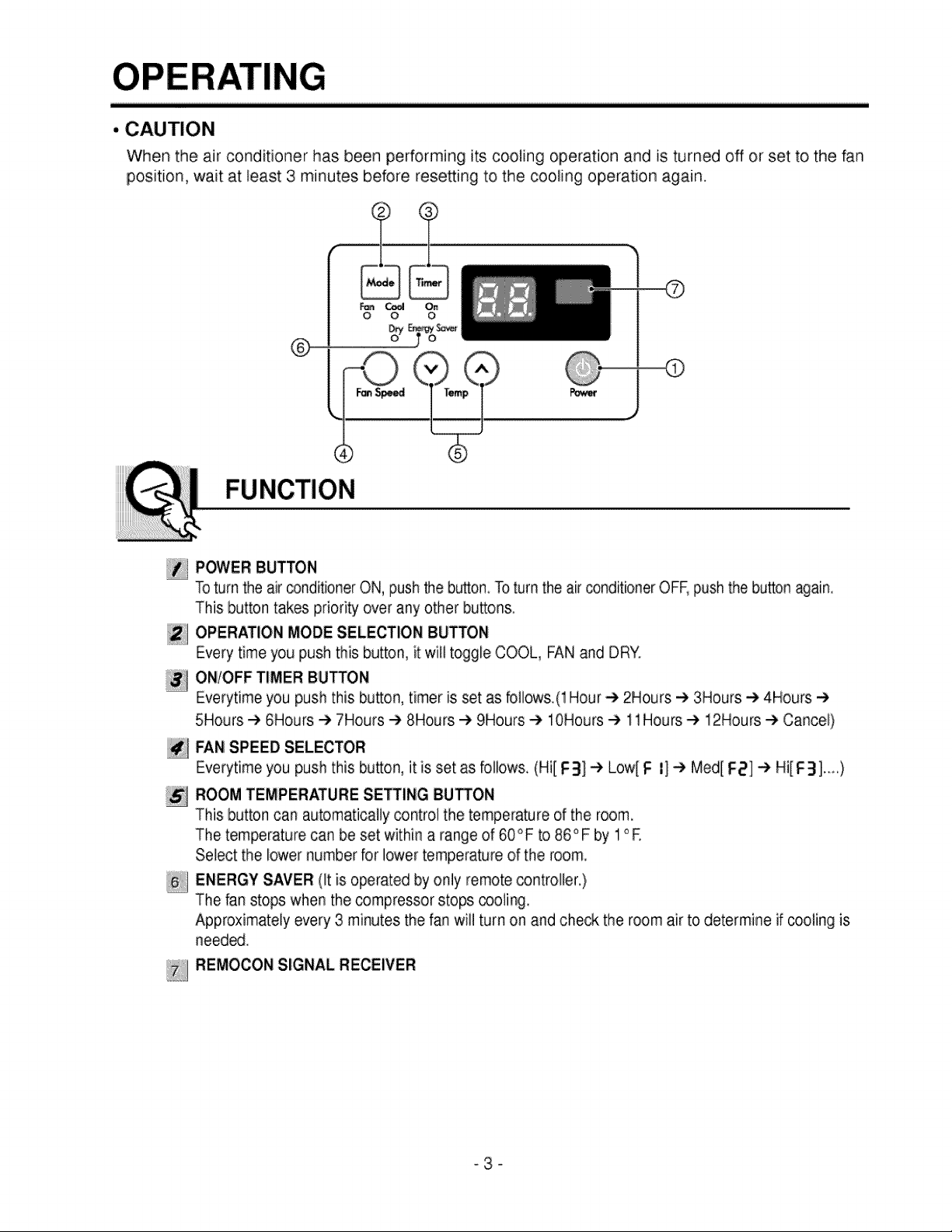
• CAUTION
When the air conditioner has been performing its cooling operation and is turned off or set to the fan
position, wait at least 3 minutes before resetting to the cooling operation again.
..........?........t
_ On
O O O
®
FUNCTION
POWER BUTTON
Toturn the air conditioner ON, push the button. Toturn the air conditioner OFF, push the button again.
This button takes priori_ over any other buttons.
OPERATION MODE SELECTION BUTTON
Every time you push this button, it will toggle COOL, FAN and DR"(.
ONIOFF TIMER BUTTON
Everytime you push this button, timer is set as follows.(1 Hour _ 2Hours _ 3Hours -) 4Hours
5Hours-_ 6Hours -) 7Hours-) 8Hours-t, 9Hours _ 10Hours-) 11Hours e, 12Hours @ Cancel}
FAN SPEED SELECTOR
Everytime you push this button, it is set as follows. (Hil F3] _ Low[ F l] e, Med[ F2] -e Hi[F3].....)
ROOM TEMPERATURE SETTING BU_ON
This button can automatically _ntrol the temperature of the room.
The temperature can be set within a range of 60°F to 86°F by 1°E
Select the lower number for lower temperature of the room.
ENERGY SAVER (It is operated by only remote controllen)
The tan stops when the _mpressor stops _oling.
Approximately every 3 minutes the fan will turn on and check the room air to determine if cooling is
need_.
REMOCON SIGNAL RECEIVER
-3-
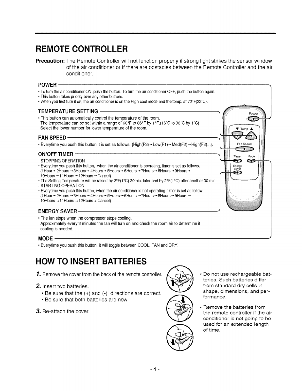
REMOTE CONTROLLER
Pir_aution: The Remote Controller will not function propedy if strong light strikes the sensor window
of the air conditioner or if there are obstacles between the Remote Controller and the air
conditioner,
, To turn theair conditior.erON, pushthe I_Jtton.To turn the air conditioner OFF,pushthe bu_onwain.
, Th_ bu_ontakes priorityov_ any other bu_ons.
• Whenyou first turn iton, theairconditioner [son the Highccol mod_ and the temp.at 72°F(22°0).
TEMPERATURE SE_ING
• This button can automatically control the tem_rature e{the room.
The temperature can be set within a range of _°F to 86°F by 1°F,(16°C to 30'C by 1°C)
Select the lower number for lower temperature o[ the room.
FAN SPEED
• EverytimeyoupushthisbuttonitMsset asfollows,{High(F3)-*Low(F1)-_Med(F2)-*High(F3).},
ON/OFF TIMER
- STOPPINGOPERATION
• Eve_i_ you pushth_ button, whenthe airconditioner is®eratJng,timer isset as fol_ows,
(1Hour-* 2Hours -*3Hours-* 4Hour-* 5Hours-4-6Hours---7Hours_8Hours -*9Hours-*
lOHours--,11Hours-* 12Hours_ Cancel)
• The Setting Tem_rature will_ rai_d by2_'F(1°C)30rain. later and by 2°F(1°C) a_er another 30 min.
- STARTINGOPERATION
• Everyti_ you push th_ button,whenthe air cond_ioneris not _erating, tier isset as Io[Iow.
(1Hour-* 2Hours -_3Hours_*4Hours _*5Hours_-6Hours _*7Hours- 8Hours_.9Hours_.
lOHours _.11Hours--.12Hours---CanceE}
ENERGY SAVER
• The fan sto_ when the compressor stops cooling_
Al@roximateiy every 3 minutes the fanwill turn on and check the room air to determine if
cooling is needed_
MODE
• Eve_time you push this bu_ton,it wil_toggle between COOL, FAN and DRY.
HOW TO INSERT BATTERIES
1. Remove the cover from the back of the remote controller.
2, Insert two batteries,
• Be sure that the (+) and (-) directions are correct.
• Be sure that both batteries are new,
3. Re-a_ach the cover,
Do not use rechargeable bat=
teries. Such batteries differ
from standard dry ceils in
shape, dimensions, and per-
folrmance.
Remove the batteries from
the remote controller if the air
conditioner is not going to be
used for an extended length
of time.

The ventilation lever must be CLOSE position in order to maintain the best cooling conditions.
When fresh air is necessary in the room, set the ventilation lever to the OPEN position.
The damper is opened and room air is exhausted.
Part
CLOSE|VENT|OPEN
NOTE: Before using the ventilation feature, make a ventilation kit
First, pull down part @ to horizontal line with part @.
TO CONTROL AIR DIRECTION
The direction of air can be controlted wherever you want to cool by adjusting the horizontal louver and
the vertical iouven
• HORIZONTAL AIR-DIRECTION CONTROL
The horizontal air direction is adjusted by
moving the vertical louver right or left.
• VERTICAL AIR-DIRECTION CONTROL
The vertical air direction is adjusted by rotating
the horizontal louver forward or backward.
HOW TO SECURE THE DRAIN PIPE
In humid weather, excess water may cause the
BASE PAN to ovediow. To drain the water,
remove the DRAIN CAP and secure the DRAIN
PIPE to the rear hoie of the BASE PAN
Drain pipe
Drain cap
-5-
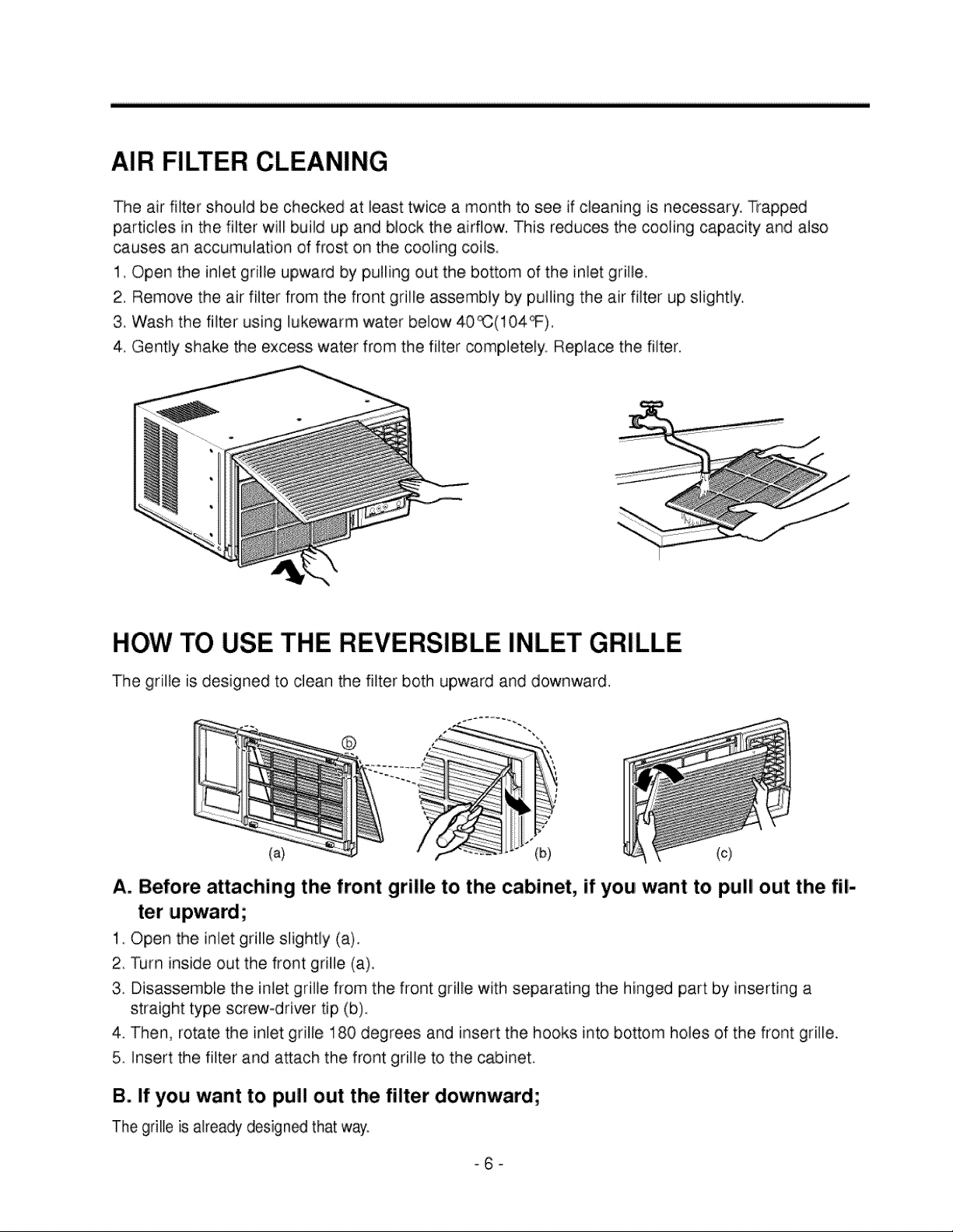
AIR FILTER CLEANING
The air filter should be checked at least twice a month to see if cleaning is necessary. Trapped
particles in the filter will build up and block the airflow. This reduces the cooling capacity and also
_uses an accumulation of frost on the cooling coils.
1. Open the inlet grille upward by pulling out the bottom of the inlet grille
2, Remove the air filter from the front grille assembly by pulling the air filter up slightly,
3. Wash the filter using lukewarm water below 40_(104_).
4, Gently shake the excess water from the filter completely. Repla_ the filter.
HOW TO USE THE REVERSIBLE INLET GRILLE
The grille is designed to caean the filter both upward and downward.
®
(a) (b)
A. Before attaching the front grille to the cabinet, if you want to pull out the fil-
ter upward;
1. Open the inlet grille slightly (a)
2. Turn inside out the front grille (a),
3. Disassemble the inlet grille from the front grille with separating the hinged part by inserting a
straight type screw-driver tip (b).
4. Then, rotate the inlet grille 180 degrees and insert the hooks into bottom holes of the front grille.
5. insert the filter and attach the front grille to the cabinet.
B. If you want to pull out the filter downward;
The griIle is already designed that way.
-6-

ELECTRICAL DATA
Line Cord Plug
circumstances, cut or
Do not, under any
remove the grounding prong
from the plug.
Power supply cord with
3-prong grounding plug
Use Wall Receptacle
Standard 125V, 3-wire grounding
receptacle rated 15A, 125V AC
BEFORE CALLING FOR SERVICE
Power Supply
Use 15 AMP, time
delay fuse or circuit
breaker.
• Air Conditioner will not operate.
1. Is the air conditioner plugged into the outlet?
2. Is the fuse or breaker good?
3. Is the voltage unusually high or low?
• Air from the unit does not feel cold enough on the cooling setting.
1. Is the setting temperature correct?
2. Is the air filter clogged with dust?
3. Is the air flow from the outside(condensers) obstructed?
Leave a clearance of over 1 meter(3.28 feet) between the back of the air conditioner and the wall or
fence behind it.
4. Are the door or windows open, or is there any source of heat in the room?
NOTE: If it is difficult to find out the cause of the trouble, be sure to turn the air conditioner off and
contact the dealer.
• OFF-SEASON MAINTENANCE
1. Clean the air filter and re-install.
2. Turn the power off and disconnect the power plug from the wall receptacle.
I
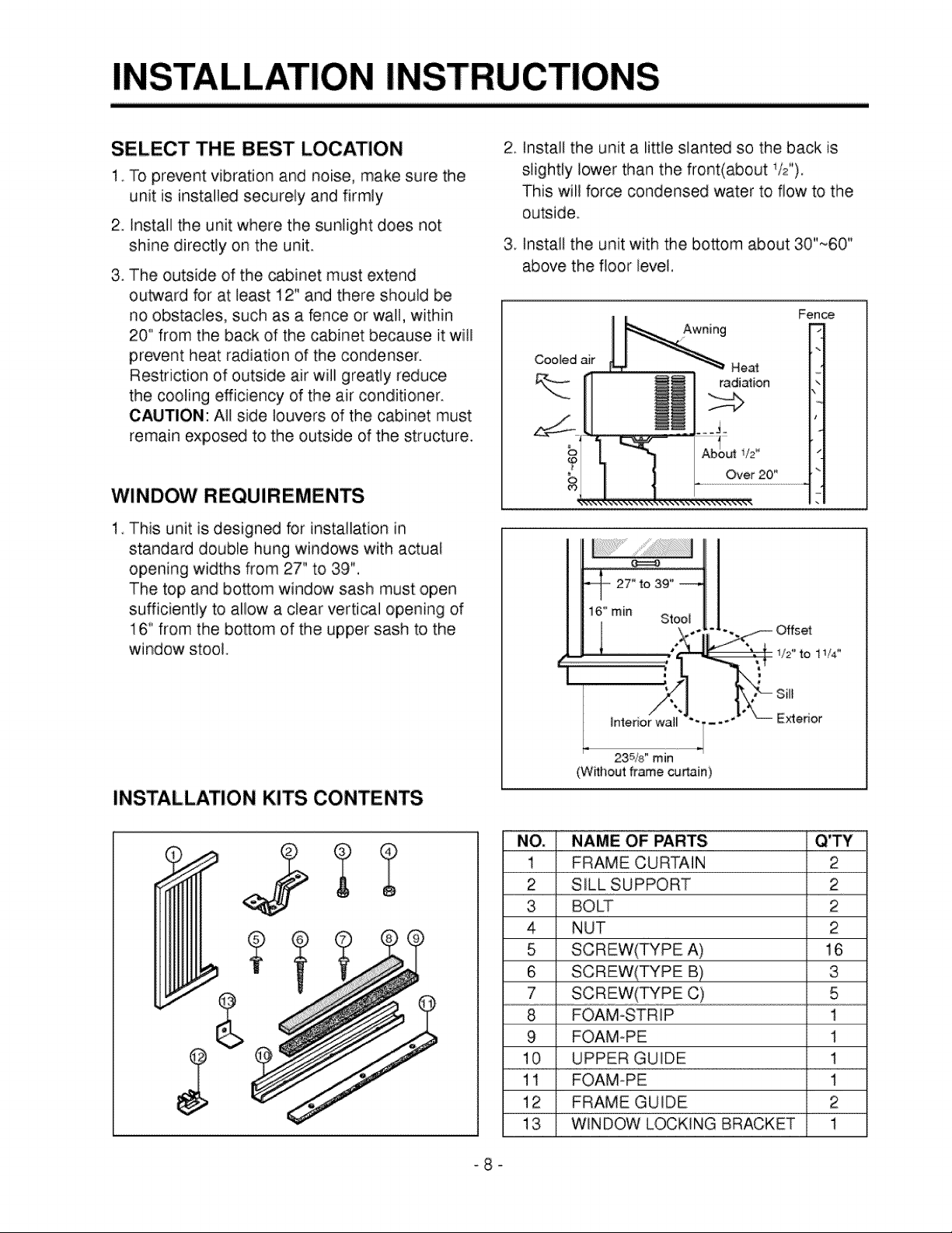
SELECT THE BEST LOCATION
1. To prevent vibration and noise, make sure the
unit is installed securely and firmly
2. Install the unit where the sunlight does not
shine directly on tlhe unit.
3. The outside of the _binet must extend
outward for at least 12" and there should be
no obstacles, such as a fence or wall, within
20" from the back of the cabinet because it will
prevent heat radiation of the condenser.
Restriction of outside air will greatly reduce
the cooling efficiency of the air conditioner.
CAUTION: All side louvers of the cabinet must
remain exposed to the outside of the structure.
WINDOW REQUIREMENTS
1, This unit is designed for installation in
standard double hung windows with actual
opening widths from 27" to 39",
The top and bottom window sash must open
sufficiently to allow a clear vertical opening of
16" from the bosom of the upper sash to the
window stool
2. Install the unit a little slanted so the back is
slightly lower than the front(about i/2").
This will force condensed water to flow to the
outside,
3 Install the unit with the bottom about 30"_60"
above the floor level,
Fence
Cooled air
HeM
radiation
%
..............................................................
.....................Ov_20_.......................
1,/2"to 11/4"
INSTALLATION KITS CONTENTS
(Without frame curtain)
NO, NAME OF PARTS,
1 FRAME CURTAIN 2
2 SILL SUPPORT 2
3 BOLT 2
4 NUT 2
5 SCREW(TYPE A) 16
6 SCREW(TYPE B) 3
7 SCREW(TYPE C) 5
8 FOAM-STRIP 1
9 FOAM-PE 1
10 UPPER GUIDE 1
11 FOAM-PE 1
12 FRAME GUIDE 2
13 WINDOW LOCKING BRACKET 1
-8-
Interior wail
235/8," rain
Exterior

SUGGESTED TOOL REQUIREMENTS
I SCREWDRIVER(+, -), RULLER, KNIFE, HAMMER, PENCIL,
PREPARATION OF CHASSIS
1. Remove the screws which fasten the cabinet
at both sides and at the back,_
2, Slide the unit from the cabinet by gripping the
base pan handle and pulling forward while
bracing the cabinet.
3. Remove EPS Material.
4. Cut the window sash seal to the proper length,
Peel off the backing and attach the foam-pe @
to the underside of the window sash,
5, Remove the backing from the top upper guide
Foam PE @ and a_ach it to the bottom of the
upper guide @,
6. Attach the upper guide onto the top of: the
cabinet with 3 type A screws,
7, insert the frame guides @ into the bottom of
the cabinet.
8. insert the Frame Curtain _') into the upper
guide @ and frame guides @.
9. Fasten the, curtains to the unit with 4 Type A
screws,
(Type
LEVEL
Shipping screws
EPS Matedal
CABINET INSTALLATION
1. Open the window. Mark a line on center of the
window stool(or desired air conditioner
location).
Carefully place the cabinet on the window
stool and align the center mark on the bottom
front with the center line marked in the
window stool.
2. Pull the bottom window sash down behind the
upper guide until it meets.
"i Do not pull the window sash down so tiglhtly
that the movement of Frame Curtain is
restricted.
(Type A)
Upper Guide
_Window stool
Front Angle Fig. 1
i_
Fig. 2
Foam-peQ

3. Loosely assemble the sill support using the
parts in Fig. 3.
4. Select the position that will place the sill
support near the outer most point on sill
(See Fig. 4)
NOTE: Be careful when you install the cabinet
(frame guides @ are broken so easily).
5. Attach the sill support to the cabinet track hole
in relation to the seiected position using
2 Type A screws in each support(See Fig. 4).
6 The cabinet should be installed with a very
slight tilt(about 1/2") downward toward the
outside (See Fig. 5),
Adjust the bolt and the nut of sill support for
baJancing the cabinet.
Frame Guide @
Screw(Type A) @
• io ....
a r _i
IND_
Fig, 4
Screw(Type B)
7, Attach the cabinet to the window stool by
driving the screws (_(Type B: Length sixteen
millimeters and below.) through the front angle
into window stool.
8. Pull each Frame curtain fully to each window
sash track, and repeat step 2.
9. Attach each Frame curtain the window sash
using screws ®(Type C).
(See Fig, 6)
Sill support
FrontAngle
_rew(Type B)
Sil_ suppod_
Fig. 5
Fig, 6
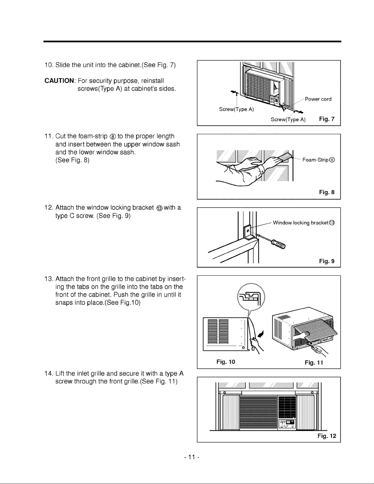
10. Slide the unit into the cabinet.(See Fig. 7)
CAUTION: For security purpose, reinstalU
screws(_pe A) at cabinet's sides.
......Power cord
11. Cut the foam-strip ® to the proper !ength
and insert between the upper window sash
and the lower window sash.
(See Fig. 8)
12, Attach the window locking bracket @with a
type C screw. (See Fig 9)
13. Attach the front grille to the cabinet by insert-
ing the tabs on the grille into the tabs on the
front of the cabinet, Push the grille in unti! it
snaps into place.(See Fig. 10)
Screw(Ty_ A)
Screw(Ty_ A) Fig. 7
/
Foam-StripQ
Fig, 8
locking bracket@
Fig. 9
14. Lift the in!et grille and secure it with a type A
screw through the front grille.(See Fig, 11)
Fig, 10 Fig, 11
Fig. 12
 Loading...