

Page 1

Room Air Conditioner
SVC MANUAL(Exploded View)
MODEL : H2UC186FA0
CAUTION
Before Servicing the unit, read the safety precautions in General SVCmanual.
Only for authorized service personnel.
http://biz.lgservice.com
H3UC246FA0
H3UC216FA0
Page 2
2 Room Air Conditioner
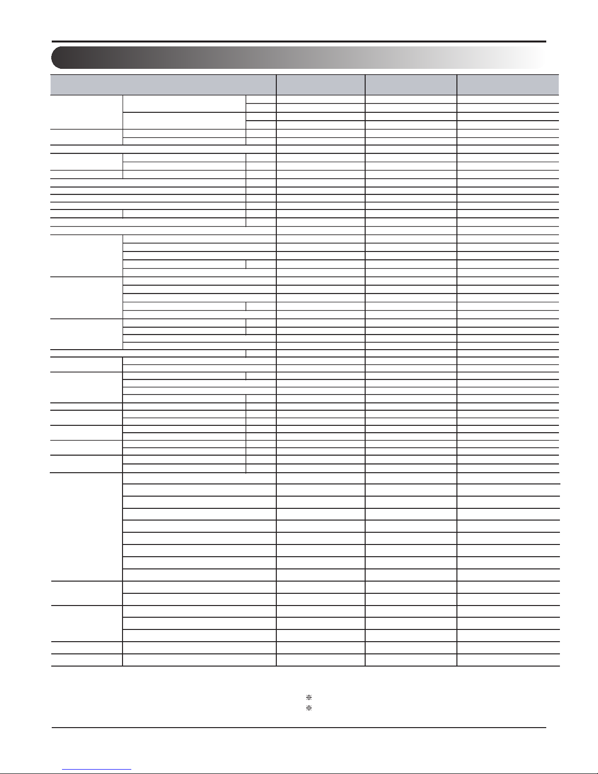
1. Specification
Note:
*
For circuit breaker rating, please conform to local standards wherever necessary.
Some of functions are slightly different depending upon models.
The specification may be subject to change without prior notice for purpose of
improvement.
O : Applied X : Not applied – : No relation
H2UC186FA0 H3UC216FA0 H3UC246FA0
kW
2.93 ~ 6.30 2.81 ~ 6.15 2.63 ~ 7.03
Btu/h
10,000
9,600 ~ 21,000 9,000 ~ 24,000
kW - - -
Btu/h - - -
Cooling kW
1.60 ~ 1.80
1.82
0.83 ~ 2.14
Heating kW - - -
HMNC126D4A0×2EA HMNC096D4A0×3EA
Cooling A
8.3 8.3
9.8
Heating A - - -
Starting Current Cooling/Heating A
59.0
59.0 54.0
1/220 ~ 240/50
1/220 ~ 240/50Hz 1/220 ~ 240/50Hz
No . ×
㎟ 3 × 2.5 3 × 2.5 3 × 2.5
No . ×
㎟ 4 × 0.75(Including Earth) 4 × 0.75(Including Earth) 4 × 0.75(Including Earth)
No . ×
㎟ - - -
Dimensions W x H x D mm(inch)
)
kg(lbs)
52(115) 53(117) 55(121)
2 3 3
ROTARY ROTARY ROTARY
1 x QP325PBA
1×QK164PBC
Induction Induction Induction
Oil charge volume cc 700 700 700
4GSI 4GSI 4GSI
- - ROTARY
- -
1×QJ250PD24C
- - Induction
Oil charge volume cc - -
410
- - 4GSI
Cycle A Charge (at 7.5m) g(oz) 1,300(45.86)
1,300(45.86) 1,300(45.86)
Cycle B Charge (at 7.5m) g(oz) - - -
R22 R22 R22
LEV LEV LEV
g/m(oz/ft) 30 (0.32) 30 (0.32) 30 (0.32)
(2R×30C×21)×1 (2R×30C×21)×1 (2R×16C×18)×1
- - -
Capacitor
6 6
6
- - -
Sound Level(H/L)
Sound Pressure dB(A)+3 54 54 56
Liquid(Cycle A) mm(inch) 6.35 6.35 6.35
Gas(Cycle A) mm(inch) 9.52 9.52 9.52
Total Piping
m
30 45 45
Each Branch Piping
m
15 15 20
Outdoor Unit~Indoor Unit
m
7.5 7.5 7.5
Indoor Unit~Indoor Unit
m
7.5 7.5 7.5
Cooling
oC(o
F)
18 - 43 18 - 43 18 - 43
Heating
oC(o
F)
- - -
Operation Range
(Outdoor)
Power and Transmission Cable(BD to Indoor)
Running Current(Rating)
Compressor (#2)
Power Supply
Power Supply Cable(Outdoor)
Net Weight
Max. Number of Connectable Indoor Units
Compressor (#1)
Power and Transmission Cable(Outdoor to Indoor or Outdoor to BD)
Motor type
Oil Type
Type
Qty x Model
Oil type
Type
Control
Additional Refrigerant Charge
Max. Elevation
Difference
Fan
Max. Interunit
Piping Length
Refrigerant
Heat Exchanger
Drive
Outdoor unit
Nominal Capacity
Cooling
Heating
Type
Qty x Model
Motor type
Nominal Input
Testing Combination
Discharge Direction(Side/Top)
Condensing unit
Service Valve
Defrosting Method
~ 21,500
Category
Function
Defrost / Deicing
- - -
High pressure switch
- - -
Low pressure switch
- - -
Phase protection
- - -
Restart delay ( 3-minutes )
O O O
Self diagnosis
O O O
Soft start
O O O
Test function
O O O
Auto operation(Artificial intelligence)
O O O
Auto restart operation
O O O
Network soluation(LGAP)
O O O
PDI(Power Distribution Indicator)
PQNUD1S00 PQNUD1S00 PQNUD1S00
PI485
PMNFP14A0 PMNFP14A0 PMNFP14A0
Special function kit Low ambient operation
×
× ×
- - -
Reliability
Convenience
CAC network
function
Ø / V/ Hz
870x655x320(34.2x25.8x12.6)
870x655x320(34.2x25.8x12.6)
HMNC096D4A0x1 + HMNC126D4A0x2
870x655x320(34.2x25.8x12.6)
1 x QP325PBA
CMM(cfm)
Side
Side
Side
51(18.01)x1
51(18.01)x1
51(18.01)x1
㎌ / vac
(Rows x Column x FPI) xNo.
Air flow Rate x No. of Fan
Others Thermistor
Page 3

Service Manual 3
Piping Diagram
Comp.
QP325P
Φ
Φ6.35
Φ6.35
B-실
A-실
Air
S ens or
Air
S ens or
E va. IN
S ens or
E va. IN
S ens or
E va. OUT
S ens or
E va. OUT
S ens or
Φ5.0 C ond.
2R 30C 2 1FP I ( 6 path)
2
3
4
5
6
7
8
9
10
11
14
15
16
17
18
20
21
22
23
24
19
12
13
1
25
26
27
28
29
30
2
3
4
5
6
7
8
9
10
11
14
15
16
17
18
20
21
22
23
24
19
12
13
1
25
26
27
28
29
30
Φ
Discharge
Sensor
A실 LE V
B실 LE V
BYPASS CAPI
(ID1.9*500mm)
Air
Sensor
Suction
Sensor
Comp.
QP325P
Φ
Φ6.35
Φ6.35
B-실
A-실
Air
S ens or
Air
S ens or
E va. IN
S ens or
E va. IN
S ens or
E va. OUT
S ens or
E va. OUT
S ens or
Φ5.0 C ond.
2R 30C 21F P I (6 path)
2
3
4
5
6
7
8
9
10
11
14
15
16
17
18
20
21
22
23
24
19
12
13
1
25
26
27
28
29
30
2
3
4
5
6
7
8
9
10
11
14
15
16
17
18
20
21
22
23
24
19
12
13
1
25
26
27
28
29
30
Φ
Discharge
Sensor
A실 LE V
B실 LE V
BYPASS CAPI
(ID1.9*500mm)
Air
Sensor
Suction
Sensor
A-실
Air
S ens or
E va. IN
S ens or
E va. OUT
S ens or
Φ6.35
B실 LE V
Φ
9.52
9.52
9.52
9.52
9.52
2. Piping Diagrams
H2UC186FA0
H3UC216FA0
Page 4

4 Room Air Conditioner
2. Piping Diagrams
Th1 :Thermistor for suction air temp.
Th2
:Thermistor for Discharge air temp.
Th3
:Thermistor for Room Out temp.
Refrigerant pipe connection port diameters
diuqiLsaGledoM
H2UC186FA0
Ø9.52 X 2 EA
Ø6.35 X 2 EA
(mm)
ex)
Solenoid Valve
L.E.V
3-Way Valve
2-Way Valve
Capillary
Air
S ens or
E va.
S ens or
Comp
A
Comp
B
Acc.
E va.
S ens or
C/V
C/V
Φ6.3 5
B-실
Φ
A실 LE V
B실 LE V
C-실
C실 LE V
A-실
Air
S ens or
Air
S ens or
E va.
S ens or
E va.
S ens or
E va.
S ens or
E va.
S ens or
Φ
Φ
Φ6.3 5
Φ6.3 5
Φ7.0 Cond.
2R 28C 18F PI
(5 path)
Discharge
Sensor
Air
Sensor
Air
S ens or
E va.
S ens or
Comp
A
Comp
B
Acc.
E va.
S ens or
C/V
C/V
Φ6.3 5
B-실
Φ
A실 LE V
B실 LE V
C-실
C실 LE V
A-실
Air
S ens or
Air
S ens or
E va.
S ens or
E va.
S ens or
E va.
S ens or
E va.
S ens or
Φ
Φ9.52
Φ6.3 5
Φ6.3 5
Φ7.0 Cond.
2R 28C 18F PI
(5 path)
Discharge
Sensor
Air
Sensor
9.52
9.52
Cond out
Sensor
H3UC216FA0
H3UC246FA0
Ø9.52 X 3 EA
Ø6.35 X 3 EA
H3UC246FA0
Page 5

Service Manual 5
3. Wiring Diagram
noitacoLrebmuNrotcennoC
ylppusrewopCACN_POWER
Signal Output
Compressor output
Pipe sensor
LGMV input
Fan motor output
yalpsiD
Models: H2UC186FA0 / H3UC216FA0 / H3UC246FA0
CN_COMP
CN_FAN
CN_SV
CN_TH1
CN_TH2
CN_LGMV
CN_LEV
CN_COM
Cond & Air sensor
LEV output
1. H2UC186FA0
3. H3UC246FA0
2. H3UC216FA0
BR
BR
WH
PCB
CN_LEV3
CN_LEV1
CN_LEV2
CN_LGMV
CN_TH1
CN_TH2
CN_SV
CN_FAN
CN_COM
CN_COMP
CN_POWER
Page 6

6 Room Air Conditioner
Exploded View & Peplacement Parts List
263230E
552200
W0CZZ
- H2UC186FA0/ H3UC216FA0
559010
349600
661400
268711
437212
552117
552112
552111
435512
546810
554031
447910
437211 430410
554160
550140
552203A
552203B
649950
435511
263230F
552204
Page 7

Exploded View & Replacement Parts List
263230E
552200B
- H3UC246FA0
437212
Service Manual
435512
552112
552114
552113
548490
549610
559010
437211
430410
546810A
447910
263230F
W0CZZA
W0CZZB
268711
554031
661400
649950
435511
554160D
554160C
550140
552203B
552203A
Page 8

P/NO : MFL30704502
Dec,
2007
 Loading...