

Page 1

REFRIGERATOR
http://biz.lgservice.com
SERVICE
CAUTION
IN
THE
THIS
BEFORE
PRECAUTIONS"
SERVICING
UNIT,
MANUAL.
MANUAL
READ
THE
"SAFETY
MODEL:
GR-J323
GR-J213
GR-J403
GR-J303
GR-J408
Page 2
SAFETY
INSTRUCTIONS
1.
Firstly
2.
Perform
3.
Weararubber
4.
Always
5.
Exercise
6.
Take
care
or
backward.
7.
Ensure
insideofthe
check
work
check
to
that
thereiselectrical
always
gloves(insulation
rated
care
so
that
so
that
things
Especially,
consult
cycle
the
gets
after
current,
water
should
take
repair
a
room
removing
gloves)
voltage
does
not
care
and
maintenance
dirty).
leakage
the
power
for
and
capacityinusing
not
enter
fall
down
of
thin
in
the
main
plugsinhandling
preventing
into
electrical
by
removing
things
(glass
center
body
electrical
parts
panels,
shop
of
the
instruments.
them
when
the
product.
with
shock
around
cleanly
books).
the
the
the
cold
part
accident
machine
on
the
storage
where
electricity
in
case
room.
product
when
cycleisdamaged
of
testing
conducts
with
leaning
the
(to
through.
power
product
prevent
on.
forward
that
gas
1.
Product
2.
Circuit
3.
MICOM
4.
Exploded
Specifications
Diagram
Function
....................................................................................................................................................................7
and
View
and
CONTENTS
..........................................................................................................................................................3
of
Explanations
Service
Parts
Circuits
List
................................................................................................................................40
....................................................................................................................8
-2-
Page 3
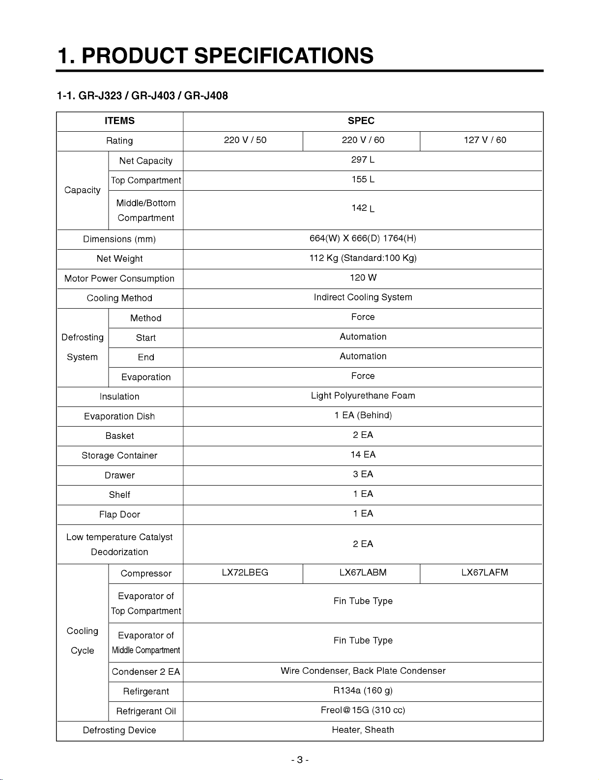
1.
1-1.
GR-J323
PRODUCT
/
GR-J403
SPECIFICATIONS
/
GR-J408
Capacity
Dimensions
Motor
Power
Cooling
Defrosting
System
ITEMS
Rating
Net
Top
Middle/Bottom
Compartment
Net
Weight
Insulation
Capacity
Compartment
(mm)
Consumption
Method
Method
Start
End
Evaporation
SPEC
220V/50 220V/60
297
155
142
664(W)X666(D)
112
Kg
(Standard:100
120
Indirect
Light
Cooling
Force
Automation
Automation
Force
Polyurethane
127V/60
L
L
L
1764(H)
Kg)
W
System
Foam
Evaporation
Storage
Low
temperature
Cooling
Cycle
Basket
Container
Drawer
Shelf
Door
Flap
Deodorization
Compressor
Evaporator
Top
Evaporator
Middle
Condenser
Refirgerant
Dish
Catalyst
of
Compartment
of
Compartment
2
1
EA
(Behind)
2EA
14
EA
3EA
1EA
1EA
2EA
LX72LBEG
EA
Wire
Condenser,
LX67LABM
Fin
Fin
R134a
Tube
Tube
Back
Type
Type
(160
Plate
g)
LX67LAFM
Condenser
Refrigerant
Defrosting
Device
Oil
-3-
Freol@15G
Heater,
(310
Sheath
cc)
Page 4
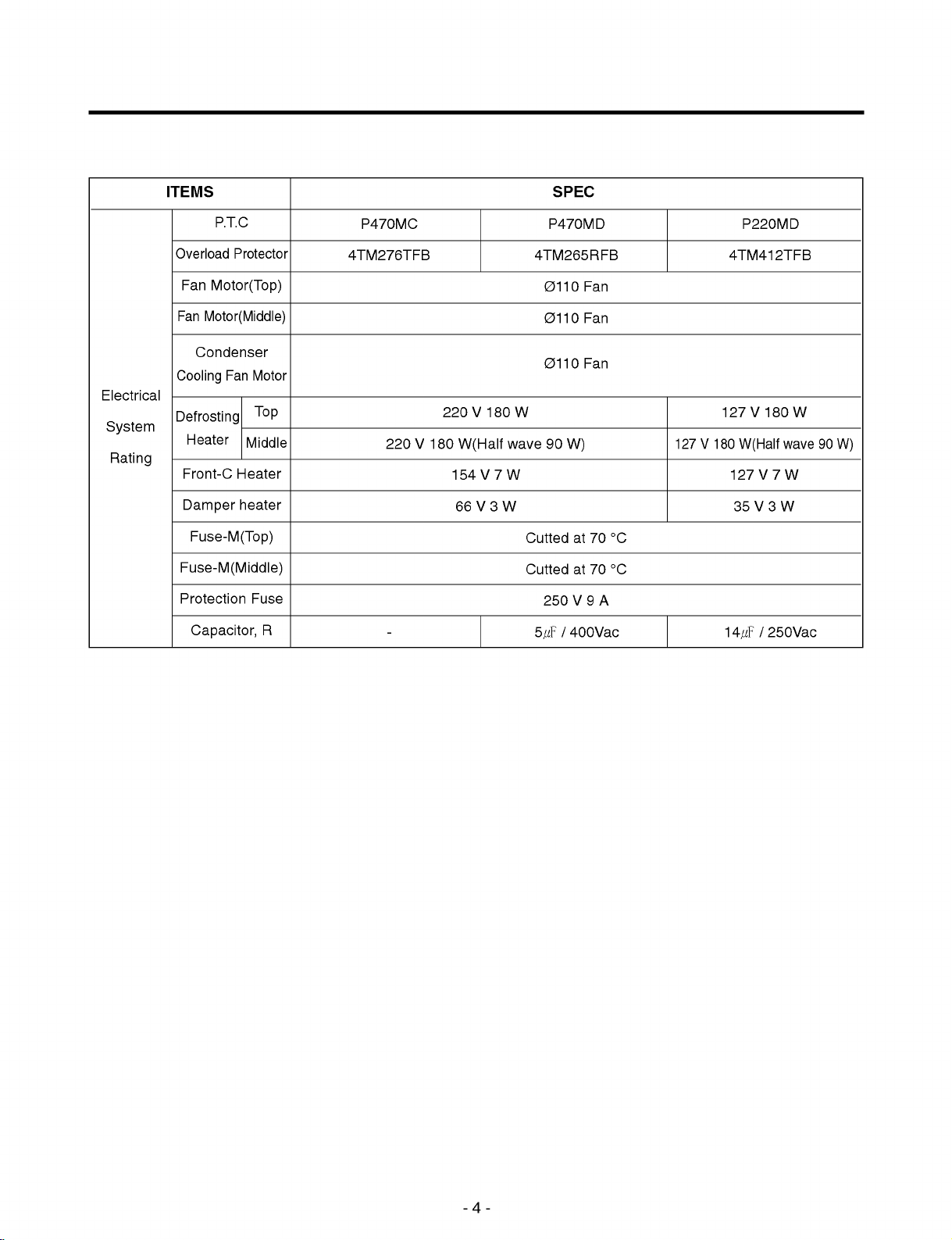
ITEMS
SPEC
Electrical
System
Rating
P.T.C
Overload
Fan
Fan
Cooling
Protector
Motor(Top)
Motor(Middle)
Condenser
Fan
Motor
Defrosting
Heater
Front-C
Damper
Middle
Heater
heater
Fuse-M(Top)
Fuse-M(Middle)
Protection
Fuse
Capacitor,
Top
R
P470MC
4TM276TFB
220V180
-5
P470MD
4TM265RFB
Ø110
Fan
Ø110
Fan
Ø110
Fan
220V180W
wave
Cutted
Cutted
250V9A
㎌
90
W)
at
70
°C
at
70
°C
/
400Vac
W(Half
154V7W 127V7W
66V3W 35V3W
127V180
4TM412TFB
127V180W
14㎌
P220MD
W(Half
/
wave
250Vac
90
W)
-4-
Page 5
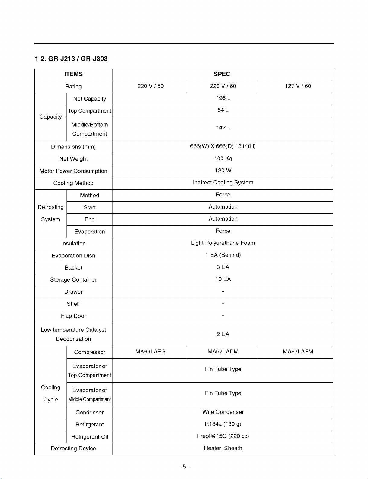
1-2.
GR-J213
/
GR-J303
Capacity
Dimensions
Motor
Power
Cooling
Defrosting
System
ITEMS
Rating
Net
Top
Middle/Bottom
Compartment
Net
Weight
Insulation
Capacity
Compartment
(mm)
Consumption
Method
Method
Start
End
Evaporation
SPEC
220V/50 220V/60
196
54L
142
666(W)X666(D)
100
120
Indirect
Light
Cooling
Force
Automation
Automation
Force
Polyurethane
127V/60
L
L
1314(H)
Kg
W
System
Foam
Evaporation
Storage
Low
temperature
Cooling
Cycle
Basket
Container
Drawer
Shelf
Door
Flap
Deodorization
Compressor
Evaporator
Top
Evaporator
Middle
Condenser
Refirgerant
Dish
Catalyst
of
Compartment
of
Compartment
MA69LAEG
1
MA57LADM
Fin
Fin
Wire
R134a
EA
3EA
10
2EA
Tube
Tube
Condenser
(Behind)
EA
-
-
-
Type
Type
(130
MA57LAFM
g)
Refrigerant
Defrosting
Device
Oil
-5-
Freol@15G
Heater,
(220
Sheath
cc)
Page 6

ITEMS
SPEC
Electrical
System
Rating
P.T.C
Overload
Fan
Fan
Cooling
Protector
Motor(Top)
Motor(Middle)
Condenser
Fan
Motor
Defrosting
Heater
Front-C
Damper
Middle
Heater
heater
Fuse-M(Top)
Fuse-M(Middle)
Protection
Fuse
Capacitor
Top
P330MC
4TM293RFB
220V180
-5
P330MD
4TM213SFB
Ø110
Fan
Ø110
Fan
Ø110
Fan
220V180W
wave
Cutted
Cutted
250V9A
㎌
90
W)
at
70
°C
at
70
°C
/
400Vac
W(Half
154V7W 127V7W
66V3W 35V3W
127V180
4TM412TFB
127V180W
12㎌
P6R8MD
W(Half
/
wave
250Vac
90
W)
-6-
Page 7

2.
CIRCUIT
DIAGRAM
-7-
Page 8

3.
3-1.
3-1-1.
(1)
GR-J323
MICOM
EXPLANATION
DISPLAY
/
GR-J403
FUNCTION
OF
PART
/
GR-J408
FUNCTION
AND
EXPLANATIONS
OF
CIRCUITS
NOTCH
Temperature
setting
Lock
Unlock
Lock
Date
Frz./
Frz.
Deep
-25°C -15°C -18°C -21°C
Frz.
Min Mid
Upper
Middle
Lower
Upper
Middle
Max
Meat
Min Mid
-1.0°C
Veg.
Frz.
Veg.
Soft
Veg.
Veg.
Frz.
Veg.
Soft
&
Fish
Max
-2.5°C -4.0°C -7.0°C
&
Fruit
Soft
Date
Soft
&
Fruit
Meat
Frz.
&
&
Fruit
Fruit
Date
Deep
Soft
&
Fruit
Meat
Frz.
Frz.
Veg.
Min Mid
4.5°C 3.5°C 2.5°C
Frz.
Frz.
&
Fish
Ref.
Frz.
Frz.
&
Fish
&
Fruit
Min
Min
Min
Min
Min
Max
Date
Ref./
Min Mid
5°C 3°C
Max
Max
Max
Max
Max
Ref.
Max
1°C
1.
2.
3.
MICOM
room
MICOM
Buzzer
Unlock
becomes
as
maintains
sound
"Veg.
&
Fruit"
neither
"Lock"
the
Lower
status
"Mid",
previous
ever
ring
in
and
display
pressing
initial
the
Veg.
application
lower
room
status
the
buttonin"Lock"
&
Fruit
of
as
"Veg.
in
power
power,
failure
&
-8-
and
Fruit"
status,
Ref.
the
upper
"Mid".
and
re-application
nor
room
performs
is
indicated
of
power.
function.
Min
Max
as
"Frz."
"Mid",
the
middle
Page 9

(2)
GR-J213
/
GR-J303
NOTCH
Temperature
setting
Lock
Unlock
Lock
Date
Frz./
Frz.
Deep
-22°C -17°C -18°C -19°C
Frz.
Min Mid
Upper
Middle
Lower
Upper
Middle
Max
Meat
Min Mid
-1.0°C
Veg.
Frz.
Veg.
Soft
Veg.
Veg.
Frz.
Veg.
Soft
&
Fish
Max
-2.5°C -4.0°C -7.0°C
&
Fruit
&
Fruit
Soft
Date
Meat
Frz.
&
&
&
Fruit
Fruit
Fruit
Date
Deep
Meat
Frz.
Frz.
Frz.
Ref.
Veg.
Min Mid
4.5°C 3.5°C
&
Fish
Frz.
&
Fish
&
Fruit
Min
Min
Min
Min
Min
Max
2.5°C5
Date
Ref./
Min Mid
°C3
Max
Max
Max
Max
Max
°C1
Ref.
Max
°C
1.
2.
3.
MICOM
room
MICOM
Buzzer
Unlock
becomes
as
maintains
sound
"Veg.
&
Fruit"
neither
"Lock"
the
Lower
status
"Mid",
previous
ever
ring
in
and
display
pressing
initial
the
application
lower
room
status
the
buttonin"Lock"
Veg.
in
power
as
&
of
power,
"Veg.
Fruit
&
failure
and
the
Fruit"
"Mid".
and
re-application
status,
Ref.
upper
nor
room
performs
is
indicated
of
power.
function.
Min
Max
as
"Frz."
"Mid",
the
middle
-9-
Page 10
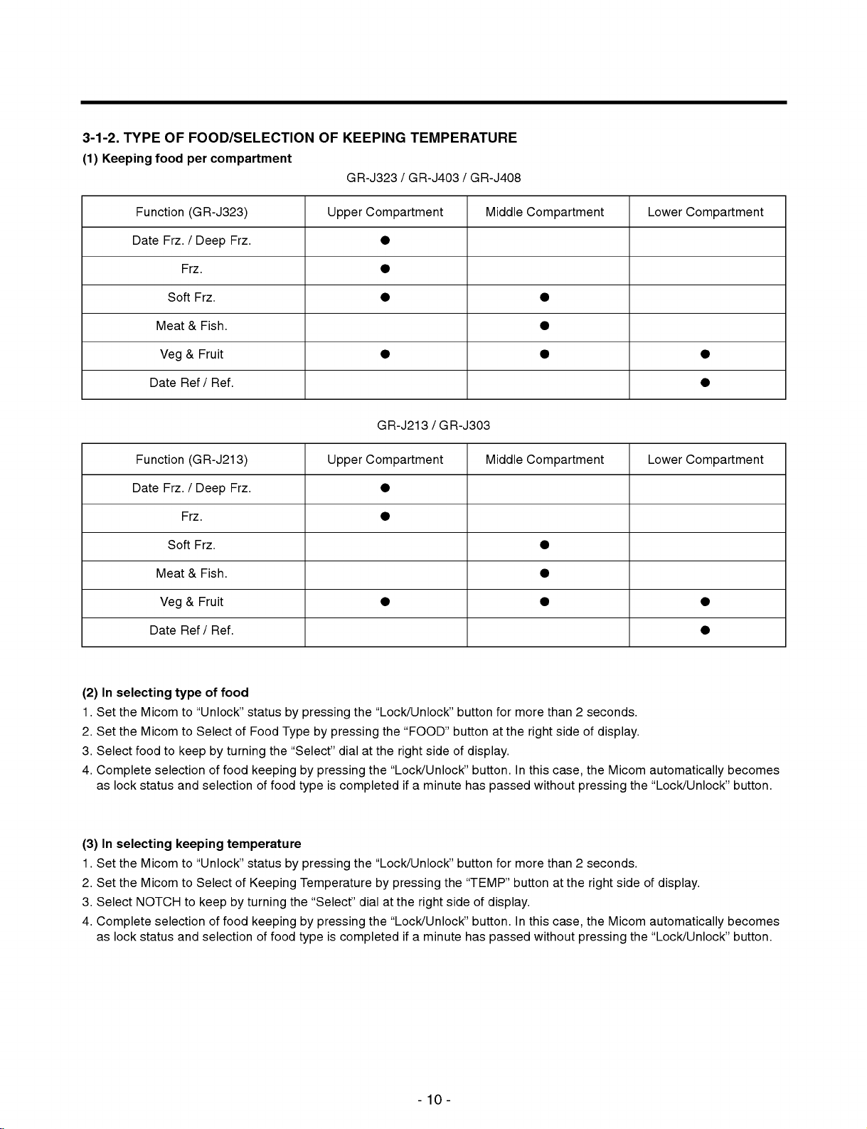
3-1-2.
(1)
TYPE
Keeping
OF
food
FOOD/SELECTION
per
compartment
OF
KEEPING
GR-J323
TEMPERATURE
/
GR-J403
/
GR-J408
Function
Date
Meat&Fish.
Veg
Date
Function
Date
Meat&Fish.
Veg
Frz.
Frz.
Soft
Ref/Ref.
Frz.
Frz.
Soft
(GR-J323)
/
Deep
Frz.
&
Fruit
(GR-J213)
/
Deep
Frz.
&
Fruit
Frz.
Frz.
Upper
Upper
Compartment
GR-J213
Compartment
/
GR-J303
Middle
Middle
Compartment
Compartment
Lower
Lower
Compartment
Compartment
Date
(2)Inselecting
1.
Set
the
Micom
2.
Set
the
Micom
3.
Select
food
4.
Complete
as
lock
status
selectionoffood
(3)Inselecting
1.
Set
the
Micom
2.
Set
the
Micom
3.
Select
NOTCH
4.
Complete
as
lock
status
selectionoffood
Ref/Ref.
of
type
to
keeping
food
to
"Unlock"
to
SelectofFood
keepbyturning
and
selectionoffood
temperature
to
"Unlock"
to
Select
to
keepbyturning
and
selectionoffood
status
by
pressing
Typebypressing
the
"Select"
keepingbypressing
type
status
by
pressing
of
Keeping
Temperaturebypressing
the
"Select"
keepingbypressing
type
the
dialatthe
is
completed
the
is
completed
"Lock/Unlock"
the
right
the
"Lock/Unlock"
"Lock/Unlock"
dialatthe
the
"Lock/Unlock"
"FOOD"
side
ifaminute
right
ifaminute
button
buttonatthe
of
display.
button.Inthis
has
passed
button
the
"TEMP"
side
of
display.
button.Inthis
has
passed
for
more
right
without
for
more
buttonatthe
without
than2seconds.
side
of
display.
the
case,
Micom
pressing
than2seconds.
right
the
case,
Micom
pressing
automatically
the
side
of
automatically
the
"Lock/Unlock"
display.
"Lock/Unlock"
becomes
button.
becomes
button.
-10-
Page 11
3-1-3.
(1)
Temperature
1.
Turn
by
opening
2.
However,
middle/lower
TEMPERATURE
COMP,
the
cooling
control
upper
compartment
3-way
of
the
compartment
CONTROL
at
upper
valvetothe
upper
compartment
is
cooling
AT
UPPER,
compartment
fan
motor
upper
compartment.
(Max25min).
depending
starts
after
MIDDLE
on
AND
temperature
cooling
of
LOWER
the
Middle/lower
of
the
COMPARTMENT
upper
compartment
compartment
sensor
is
completed
and
cool
while
them
the
(2)
Temperature
1.Turn
COMP,
them
by
opening
2.
However,
upper
compartment
(3)
Operation
1.
COMP
turns
2.
COMP
turns
(4)
Operation
1.
2.
Open
Perform
the
operation
(unsatisfactory
the
valvetoother
input
case.
LOCK
"Lock"
the
"Lock"
lower
of
all
sound
LED
with
middle,
3.
In
when
other
3-1-4.
1.
The
2.
Turn
3.
Buzzer
"Lock"
4.
The
minute
control
middle
cooling
conditions
on
offbythe
conditions
upper,
compartment
the
3-way
of
the
is
the
by
middle
for
at
middle/lower
cooling
of
upper
upper
of
and
minimum
temperature)
side.Inthis
compartment)
initial
power,
cool
upper/middle/lower
FUNCTION
LEDisturned
"Unlock"
neither
turned
LED
the
"Unlock"
LED
automatically
on
by
rings
on.
LED
middle/lower
fan
valvetothe
(Max35min).
COMP
compartment
compartment
3-way
lower
25
at
the
case,
have
from
the
compartment
(DISPLAY
in
the
pressing
ever
by
turns
turned
compartment
motor
middle/lower
compartment
valve
compartment
minutes
other
side
immediately
not
passed.
upper
BUTTON
Lock
status
the
Lock/Unlock
pressing
on
and
on.
depending
on
temperature
compartment
starts
after
sensor
sensor,
is
and
middle
valvebythe
35
minutes
(for
while
COMP
cutoff
compartment
not
satisfactory,
lower
compartment
at
operates
the
valve
where
LOCK/UNLOCK)
in
applicationofrefrigerator
button
for2seconds
button
lock
other
status
any
becomes
,and
cooling
compartment
middle
upper,
middle,
and
than
lower
with
if
temperature
the
upper
firstly
the
unless
of
the
opening
of
the
upper
sensor.
sensor
or
compartment)
the
valve
compartment
cool
from
power.
or
more
Lock/Unlock
operating
middle/lower
the
middle/lower
compartment
and
lower
lower
compartment
opened
is
met
the
to
allow
button,
the
compartment
even
is
middle,
operation
display
compartment
damper.
is
completed
sensor
upon
request
in
one
side,
if25minutes
Data
Frz.
lower
compartment
nor
performs
button
(Deep
of
for
sensor
sensor.
of
and
the
function
more
.
"open"
then
minutes
(35
Frz),
display
while
than
and
cutoff
Frz.
for
button.
with
cool
the
for
the
the
a
-11-
Page 12
3-1-5.
FRONT-C
1.
A
heater
compartment,
2.
It
turns
offinthe
3-1-6.
BUZZER
1.
"Ding~Dong~"
2.
No
buzzer
3-1-7.
POWER
1.
Previous
is
excluded.
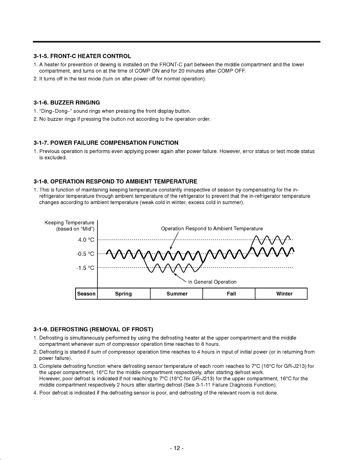
3-1-8.
OPERATION
1.
Thisisfunction
refrigerator
changes
HEATER
for
preventionofdewing
and
turnsonat
test
mode
CONTROL
(turn
RINGING
sound
ringsifpressing
FAILURE
rings
when
the
COMPENSATION
operationisperforms
RESPOND
of
maintaining
temperature
according
to
through
ambient
is
installedonthe
the
timeofCOMP
on
after
pressing
button
not
even
applying
TO
AMBIENT
keeping
ambient
temperature
off
power
the
front
according
FUNCTION
power
temperature
temperature
(weak
FRONT-C
ON
and
for
normal
display
to
the
again
TEMPERATURE
constantly
of
cold
in
part
for20minutes
operation).
button.
operation
after
power
irrespective
the
refrigerator
excess
winter,
between
order.
failure.
after
to
cold
the
COMP
However,
of
season
prevent
in
summer).
middle
that
compartment
OFF.
error
by
compensating
the
in-refrigerator
and
statusortest
for
the
lower
mode
status
the
in-
temperature
Keeping
Temperature
(basedon"Mid")
4.0
-0.5
-1.5
Season
3-1-9.
DEFROSTING
1.
Defrostingissimultaneously
compartment
2.
Defrosting
power
3.
Complete
the
upper
However,
middle
4.
Poor
defrostisindicatedifthe
whenever
is
started
failure).
defrosting
compartment,
poor
compartment
if
function
defrostisindicated
°C
°C
°C
(REMOVAL
performedbyusing
sum
of
compressor
sum
of
compressor
where
16°C
for
respectively
defrosting
Spring
OF
defrosting
the
middle
if
not
2
hours
FROST)
operation
operation
compartment
reaching
after
sensor
Operation
the
defrosting
time
sensor
to
7°C
starting
is
poor,
Summer
time
reaches
reaches
temperature
respectively,
for
(16°C
defrost
and
(See
defrosting
General
to
to
4
of
6
hours
each
to
hours.
after
Respond
In
heateratthe
GR-J213)
3-1-11
of
Ambient
Operation
upper
in
room
starting
for
Failure
the
relevant
Temperature
Fall
compartment
of
input
reaches
defrost
the
upper
Diagnosis
initial
to
7°C
work.
compartment,
room
is
and
the
power
(orinreturning
(16°C
Function).
not
done.
Winter
middle
for
16°C
GR-J213)
for
from
for
the
-12-
Page 13
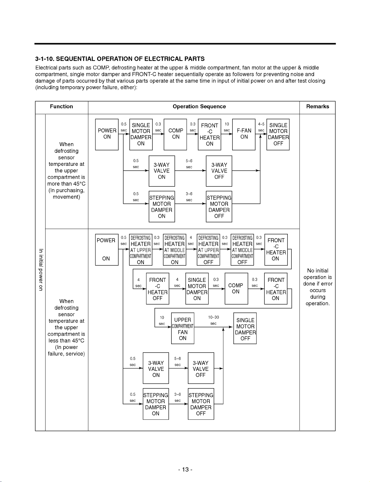
3-1-10.
Electrical
SEQUENTIAL
compartment,
damage
of
(including
such
parts
single
parts
temporary
as
motor
occurred
power
OPERATION
COMP,
damper
by
failure,
defrosting
that
various
either):
and
OF
ELECTRICAL
heateratthe
FRONT-C
parts
operate
heater
PARTS
&
upper
sequentially
at
the
same
middle
compartment,
operate
time
in
as
input
followers
of
initial
fan
motor
for
power
at
the
upper
preventing
on
and
after
noise
&
test
middle
and
closing
Function
When
POWER
Operation
0.5
SINGLE
sec
ON
MOTOR
DAMPER
0.3
sec
COMP
ON
ON
0.3
sec
Sequence
FRONT
-C
HEATER
ON
10
sec
F-FAN
4~5
SINGLE
sec
ON
MOTOR
DAMPER
OFF
Remarks
defrosting
sensor
temperature
the
compartment
more
than
(In
purchasing,
at
upper
is
45°C
movement)
POWER
ON
In initial power on
When
defrosting
sensor
temperature
the
compartment
less
than
(In
failure,
at
upper
is
45°C
power
service)
0.5
sec
0.5
sec
0.5
sec
DEFROSTING
HEATER
AT
UPPER
COMPARTMENT
ON
4
sec
0.5
sec
3-WAY
VALVE
STEPPING
MOTOR
DAMPER
0.3
sec
FRONT
-C
HEATER
OFF
3-WAY
VALVE
ON
ON
ON
DEFROSTING
HEATER
AT
COMPARTMENT
10
sec
MIDDLE
ON
4
sec
UPPER
COMPARTMENT
FAN
ON
5~6
sec
5~6
sec
3~6
sec
4
sec
SINGLE
MOTOR
DAMPER
DEFROSTING
HEATER
AT
UPPER
COMPARTMENT
OFF
ON
3-WAY
VALVE
OFF
3-WAY
VALVE
OFF
STEPPING
MOTOR
DAMPER
OFF
0.3
sec
10~30
sec
0.3
sec
COMP
DEFROSTING
HEATER
AT
MIDDLE
COMPARTMENT
OFF
ON
SINGLE
MOTOR
DAMPER
OFF
0.3
FRONT
sec
-C
HEATER
ON
No
initial
if
during
is
error
0.3
FRONT
sec
-C
HEATER
ON
operation
done
occurs
operation.
0.5
STEPPING
sec
MOTOR
DAMPER
ON
3~6
sec
STEPPING
MOTOR
DAMPER
OFF
-13-
Page 14

3-1-11.
(1)
1)
1.
2.
3.
FAILURE
Failure
GR-J323
Failure
during
Functionisneither
The
Mode
/
diagnosis
use
product
(RESET).
4.
LEDs
other
DIAGNOSIS
GR-J403
functionisintended
occurs.
done,
returns
than
failure
/
GR-J408
to
nor
normal
code
FUNCTION
buzzer
operation
turn
off
in
order
sound
rings
if
failureisreleased
in
occurrence
that
service
even
of
when
failure.
is
easily
pressing
during
done
the
display
when
button
of
failure
failuretoaffect
in
occurrence
code
in
performance
of
failure.
occurrence
of
of
the
failure
product
NO
1
Failure
compartment
sensor
2
Failureofmiddle
compartment
sensor
3
Failureoflower
compartment
sensor
4
Failure
compartment
defrosting
5
Failureofmiddle
compartment
defrosting
6
sensor
ambient
temperature
7
Failure
motor
8
Poor
upper
9
Poor
middle
10
Poor
communication
Item
of
upper
of
upper
sensor
sensor
Failure
sensor
of
single
damper
defrosting
compartment
defrosting
compartment
Lock
Unlock
(K1)
(K2)
(K3)
of
at
at
Upper
Middle
Lower
Failure
(Food
F1F2F3F4F5
Note
"Failure
Display
LED)
1)
F1
F2
F3
F4
F5
Display
Upper
or
Middle
disconnected
Lower
or
Upper
disconnected
Middle
disconnected
Ambient
disconnected
When
dectected
motor
When
does
hours
When
does
two
When
done
&
Veg.
Frz.
&
Veg.
Soft
Frz.
&
Veg.
Part"
compartment
shorted
compartment
compartment
shorted
compartment
compartment
temperature
ON/OFF
damper
defrosting
not
reach
have
defrost
not
reach
hours
no
for30seconds
Fruit
Fruit
Fruit
or
shorted
or
shorted
or
shorted
or
shorted
of
even
when
for2minutes
sensor
to
more
after
passed
sensor
to
more
have
passed
communication
Deep
Soft
Meat
Ref.
Failures
sensor
sensor
sensor
defrosting
defrosting
sensor
the
reed-S/W
driving
at
the
than
starting
at
the
than
after
Frz.
Frz.
&
Fish
is
disconnected
is
is
disconnected
sensor
sensor
is
is
the
single
upper
compartment
7°C
even
when
defrost
middle
compartment
16°C
even
starting
is
consecutively
not
when
defrost
is
two
Min
Min
Min
is
Max
Max
Max
*
Check
relevant
Damper
frozen,
IC(photo
Short
of
short
of
drain,
poor
Short
of
short
of
drain,
poor
Taking
TR
on
:ON
Remarks
wiringofrespective
sensor.
motor
damaged,
coil
damaged,
coupler)
temperature
heater,
heater
temperature
heater,
heater
out
of
connector,
communication
failure
fuse,
clogging
driving
fuse,
clogging
driving
driving
:OFF
of
relay
of
relay
Poor
part
Note1)All
and
LEDs
"TEMP"
except
button
for
failure
forasecond
display
LED
where
(F1,
poor
F2,
ambient
F3,
-14-
F4,
F5)
temperature
turn
on
if
simultaneously
sensor
exists.
pressing
both
"FOOD"
button
Page 15

2)
GR-J213
/
GR-J303
Unlock
NO
1
Failure
compartment
sensor
2
Failureofmiddle
compartment
sensor
3
Failureoflower
compartment
sensor
4
Failure
compartment
defrosting
5
Failureofmiddle
compartment
defrosting
6
Failureofambient
Temperature
sensor
Lock
Item
of
of
upper
upper
sensor
sensor
(K1)
(K2)
(K3)
Upper
Middle
Lower
Failure
(Food
F1F2F3F4F5
"Failure
Display
LED)
Note
F1
F2
F3
F4
F5
1)
Veg.
Frz.
Veg.
Soft
Veg.
Display
Upper
or
Middle
disconnected
Lower
or
Upper
disconnected
Middle
disconnected
Ambient
disconnected
&
&
Frz.
&
Part"
compartment
shorted
compartment
compartment
shorted
compartment
compartment
Fruit
Fruit
Fruit
Failures
or
shorted
or
shorted
or
shorted
temperature
or
shorted
Date
Meat
Date
sensor
is
sensor
is
sensor
is
defrosting
defrosting
sensor
Frz.
&
Fish
Ref.
disconnected
disconnected
sensor
sensor
is
Min
Min
Min
*
Check
is
is
relevant
Max
Max
Max
:ON
Remarks
wiringofrespective
sensor.
:OFF
7
motor
8
upper
compartment
9
middle
compartment
10
communication
Failure
Poor
Poor
Poor
of
single
damper
defrosting
defrosting
When
ON/OFF
dectected
motor
damper
at
at
When
defrosting
compartment
7°C
even
after
starting
When
defrost
compartment
16°C
even
after
starting
When
no
done
for30seconds
of
when
for2minutes
does
two
defrost
sensor
does
when
defrost
-15-
the
sensor
two
even
when
communication
reed-S/W
driving
not
hours
at
not
hours
the
at
the
reach
to
have
the
middle
reach
to
have
is
consecutively
is
single
upper
more
passed
more
passed
not
than
than
Damper
frozen,
IC(photo
Short
of
short
of
drain,
poor
Short
of
short
of
drain,
poor
Taking
TR
on
motor
coil
damaged,
damaged,
coupler)
temperature
heater,
clogging
heater
temperature
heater,
clogging
heater
out
of
connector,
communication
driving
failure
fuse,
driving
fuse,
driving
part
of
relay
of
relay
Poor
Page 16
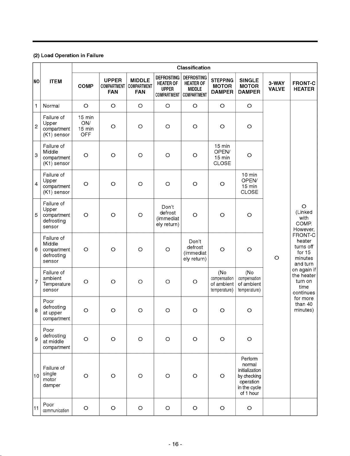
(2)
Load
Operation
in
Failure
Classification
NO
Normal
1
Failure
Upper
2
compartment
(K1)
Failure
Middle
3
compartment
(K1)
Failure
Upper
4
compartment
(K1)
Failure
Upper
5
compartment
defrosting
sensor
Failure
Middle
6
compartment
defrosting
sensor
Failure
ambient
7
Temperature
sensor
Poor
defrosting
8
at
compartment
ITEM
upper
sensor
sensor
sensor
UPPER
COMP
of
of
of
of
15
ON/
15
OFF
COMPARTMENT
FAN
O
min
min
O
O
O
O
O
O
O
O
MIDDLE
COMPARTMENT
FAN
O
O
O
O
O
DEFROSTING
HEATER
UPPER
COMPARTMENT
Don't
defrost
(immediat
ely return)
DEFROSTING
OF
HEATER
MIDDLE
COMPARTMENT
O
O
O
O
O
O
O
O
O
STEPPING
OF
MOTOR
DAMPER
O
O
15
min
OPEN/
15
min
CLOSE
O
O
SINGLE
MOTOR
DAMPER
10
OPEN/
15
CLOSE
3-WAY
VALVE
O
O
O
min
min
O
FRONT-C
HEATER
O
(Linked
with
COMP.
However,
of
O
of
O
O
O
O
O
O
O
O
O
O
O
Don't
defrost
(immediat
ely return)
O
O
O
(No
compensation
of
ambient
temperature)
O
O
(No
compensation
of
ambient
temperature)
O
O
FRONT-C
heater
turns
for
minutes
and
turn
on
again
the
heater
turn
time
continues
for
more
than
minutes)
off
15
if
on
40
Poor
defrosting
9
at
compartment
Failure
single
10
motor
damper
Poor
11
communication
middle
O
of
O
O
O
O
O
O
O
O
O
O
O
O
O
O
O
O
O
O
Perform
normal
initialization
by
checking
operation
in
the
cycle
of1hour
O
-16-
Page 17
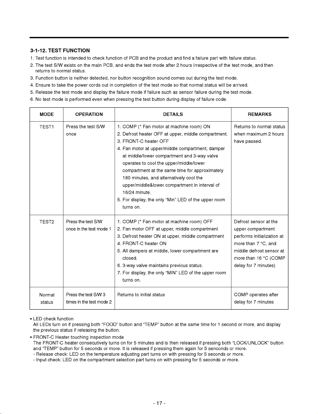
3-1-12.
1.
Test
functionisintended
2.
The
test
returns
3.
Function
4.
Ensure
5.
Release
6.
No
test
TEST
FUNCTION
S/W
existsonthe
to
normal
buttonisneither
to
take
the
the
test
mode
is
status.
power
mode
and
performed
to
check
main
detected,
cords
display
even
functionofPCB
and
PCB,
nor
button
out
in
completion
the
failure
when
pressing
and
ends
the
recognition
of
modeiffailure
the
test
the
test
the
test
button
product
mode
sound
and
after2hours
comes
mode
so
such
as
during
findafailure
irrespective
out
during
that
normal
sensor
failure
display
of
the
status
during
failure
with
part
of
the
test
willbearrived.
the
code.
failure
mode.
test
test
status.
mode,
mode.
and
then
MODE
TEST1
TEST2
Press
once
Press
once
OPERATION
the
the
test
in
the
test
test
S/W
S/W
mode
1.
COMP
2.
Defrost
3.
FRONT-C
4.
Fan
at
middle/lower
operates
compartment
180
upper/middle&lower
16/24
5.
For
turns
1.
COMP
1
2.
Fan
3.
Defrost
4.
FRONT-C
5.
All
dampers
closed.
6.
3-way
7.
For
turns
Fan
(*
heater
motor
to
minutes,
minute.
display,
on.
Fan
(*
motor
heater
valve
display,
on.
motor
OFF
heater
OFF
at
upper/middle
compartment
cool
the
at
the
and
alternatively
the
only
motor
OFF
at
upper,
ON
heater
ON
at
middle,
maintains
the
only
DETAILS
at
at
machine
upper,
room)
middle
compartment,
and
3-way
upper/middle/lower
same
time
for
approximately
cool
of
room)
compartment
middle
compartment
status.
LED
of
in
the
the
compartment
"Min"
at
machine
middle
at
upper,
lower
previous
"MIN"
LED
ON
compartment.
damper
valve
the
interval
upper
OFF
compartment
are
upper
room
of
room
Returns
when
maximum
have
passed.
Defrost
upper
compartment
performs
more
than
middle
more
than16°C
for
delay
REMARKS
to
normal
sensor
initialization
7
°C,
defrost
7
minutes)
at
sensor
status
2
hours
the
and
(COMP
at
at
?
LED
All
the
?
FRONT-C
The
and
-
-
Normal
status
check
LEDs
previous
FRONT-C
"TEMP"
Release
Input
turn
check:
function
status
Heater
button
check:
Press
timesinthe
on
if
pressing
touching
heater
LED
LED
on
the
test
test
both
if
releasing
inspection
consecutively
for5seconds
on
the
the
compartment
S/W
3
mode
2
"FOOD"
the
button.
turns
or
more.
temperature
Returns
button
mode
selection
to
and
on
for5minutes
Itisreleased
adjusting
part
initial
"TEMP"
part
turns
status
buttonatthe
andisthen
if
pressing
turns
on
-17-
on
with
them
with
pressing
same
released
again
pressing
time
for1second
if
pressing
for5senconds
for5seconds
for5seconds
both
or
or
more.
COMP
delay
or
more,
"LOCK/UNLOCK"
or
more.
more.
operates
for7minutes
and
after
display
button
Page 18

3-2.
3-2-1.
Power
(BD1,
to
transfer
IC
and
maintain
EXPLANATION
POWER
circuits
consistofSMPS
to
energy
the
feed
it
uniformly.
convert
CE1)
CIRCUIT
of
back
the
part
OF
AC
primary
(IC4,
CIRCUITS
voltage
IC5)
(Switching
to
DC
sideonthe
to
feedback
Mode
voltage,
switching
Power
the
the
Supply)
switching
terminal,
secondary
power,
part
(IC3)
secondary
side
voltage
and
to
the
switch
side
to
SMPS
power
the
consistsofthe
the
converted
to
supply
primary
rectification
DC
voltage,
to
power
sideoftransformer
the
a
transformer
MICOM
in
order
part
and
to
Caution.:
Voltage
Part
Take
circuits
of
each
Voltage
3-2-2.
OSCILLATION
Oscillation
circuits
synchronization
elements
time
not
insideofthe
calculation.
operate
or
changes.
3-2-3.
RESET
The
reset
circuits
startedatthe
insideofthe
MICOM
againininput
"LOW"
voltageisapplied
fixed
time
(10ms)
During
general
in
operates
case
a
measure
since
part
Both
220
are
for
information
Rated
time
calculated
CIRCUIT
are
initial
status
of
initial
at
the
operation,
of
poor
after
high
voltage
isasfollows:
ends
of
VA1
Vac
CIRCUIT
intended
IC1
(MICOM)
must
parts
at
intended
by
initializing
when
(IC1)
power
start
to
the
reset
or
the
of
reset
more
to
generate
than3minutes
(DC310V)
Both
ends
310
clock
is
maintained
of
Vdc
for
have
CE1
transmission/receiptoflogic
and
be
the
IC1
so
that
power
by
temporary
reset
terminalofMICOM
power
terminal
generate
used
changes
the
various
is
input.
whole
applied
since
power
isat5V
basic time
the
where
of
function
parts
to
OSC1
such
MICOM
failure.
(No
IC).
SPEC
as
for
MICOM
passed
at
Both
for
does
is
ram
the
the
ends
16
after
power
Vdc
removing
terminal.
of
CE2
the
power
Otherwise,
Both
ends
12.5
cordsinabnormal
it
cause
may
of
CE3
Both
Vdc
operation
electric
ends
5
Vdc
shock.
of
of
CE4
-18-
Page 19

3-2-4.
(1)
LOAD/BUZZER
Load
Drive
Circuit
DRIVE
CRICUIT
Mechanical
Single
Front-C
Ref.
Frz.
Frz.
Ref.
area
Motor
Heater
Defrost
Defrost
FAN
FAN
FAN
Damper
Heater
Heater
<*127V
deleted>
Type
Measuring
Status
of
Load
Point(IC7)
ON
OFF
COMP,
Mechanical
Area
No.10
FAN
UPPER
FAN
MOTOR
No.16
UPPER
DEFROST
HEATER
No.12
-19-
MIDDLE
MOTOR
Q1
Within
11~13V
FAN
Collector
1V
MIDDLE
DEFROST
HEATER
No.11
SINGLE
MOTOR
DAMPER
Q2
Colletor
FRONT-C
HEATER
No.14
Page 20

(2)
Buzzer
Drive
Circuit
Located
at
Display
PCB
[LED
MODULE]
Measuring
IC101
IC101
3-2-5.
SWITCH
Following
motor
single
part
(No.61
(No.62
circuits
Status
pin)
pin)
damper.
INPUT
are
when
5V
0V
5V
0V
input
CIRCUIT
circuits
Ding-Dong
a
display
0.05s
4.3KHz
for
sounds
button
0.2s 0.1s 0.5s
(Ding)
detecting
3.9KHz
signal
is
pressed
(Dong)
of
the
test
when
switch
an
for
Ding
incorrect
0.05s
3.9KHz
checking
sounds
button
0.2s
(Ding)
refrigerator
is
pressed
or
the
reed
OFF
5V
0V
switchofthe
-20-
REED
Switch
Page 21

3-2-6.
TEMPERATURE
SENSING
CIRCUIT
(LED
MODULE:6871JB1308)
AMBIENT
(UPPER
(MIDDLE
(LOWER
(UPPER
(MIDDLE
TEMPERATURE
SENSOR)
SENSOR)
SENSOR)
DEFROST
DEFROST
SENSOR
SENSOR)
SENSOR)
Above
circuits
and
lower
the
middle
temperature.
Sensor
Ambient
Sensor
Upper
Middle
Sensor
Lower
Sensor
Defrost
Upper
Middle
Defrost
consistofthe
compartment,
defrost
sensor
Statusinshort
Sensor
temp.
Sensor
Sensor
the
attached
upper
ambient
or
open
Check
POINT
POINT
POINT
POINT
POINT
POINT
sensor,
temperature
to
the
evaporator
are
as
points
ⓐVoltage
ⓑVoltage
ⓒVoltage
ⓓVoltage
ⓔVoltage
ⓕVoltage
middle
follows:
sensor,
sensor
Normal
to
at
the
0.5V~4.5V
lower
detect
upper,
(-30
-21-
°C
sensor
ambient
middle
~
50
for
adjusting
air
compartment
°C)
setup
temperature,
to
In
Short
0V
temperature
the
upper
detect the
at
defrost
defrost
the
upper,
sensor
return
In
middle
and
Open
5V
Page 22

3-2-7.
TEMPERATURE
1.Temperature
motor
damper,
2.
Drives
the
as
failure
3.
Rotates
once
inspection).
Motor
Single
adjustment
to
motor,
3-1-11.
(See
for15seconds
Damper
SENSING
at
or
open
andifthere
close
Failure
the
lower
the
is
no
Diagnosis
irrespective
CIRCUIT
compartment
baffle
and
status
change
Function).
of
consistsofthe
the
reed
of
the
temperature
switch
reed
to
part
switch
detect
circuit
to
detect
within
damper
for
part
open/close
2
minutes,
status
driving
in
input
the
damper,
status
determines
of
of
initial
as
electronic
the
damper.
itasfailure
power
(initial
and
drive
single
displays
4.
Open/Close
<SINGLE
Open/Close
Position
of
lower
Single
Reed
IC1
No.1
of
the
MOTOR
damper
Damper
Switch
(MICOM)
pin
Lower
damper,
DAMPER>
status
input
Damper
Open
status
OPEN
CLOSE
ON
OFF
"H":5V
"L":0V
status
of
the
reed
Operation
switch
2sec
and
No.1
pin
input
Stop
of
the
IC1
(MICOM)
are
as
follows:
Close
Operation
u
The
above
timeistime
until
the
single
motor
stops
after
status
-22-
change
of
the
reed
switch.
Stop
Page 23

3-2-8.
LOWER
STEPPING
STEPPING
MOTOR
MOTOR
DAMPER
DAMPER
GR-J213/GR-J303
DRIVE
CIRCUIT
DELETED
(FOR
TEMPERATURE
CONTROL
AT
MIDDLE
COMPARTMENT)
As
for
motor
and
the
stator
after
applying
Explanation)
drive,
52
figure
IC12
IC12
IC12
IC12
if
outputting
"High"
For
driving
and
15
via
motor
rotates
CCW
No.3
No.6
No.15
No.10
the
signal
51
the
coils
by
to
the
(INA)
(INB)
motor
rotates
"High"
to
the
method
as
shown
terminal
input
wound
which
motor
input
(reverse
(A)
(B)
since
"Low"
IC
12
of
the
in
waveform
around
coils
part
(No.3
rotation)
rotation
signal
(TA777AP)
motor,
No.3,
each
wound
INA,
<STEPPING
as
send
of
8
6,
phase
No.6
magnetic
much
from
signal
each
of
the
of
around
IC12
the
INB)
as
the
part
each
the
in
below.
stator
of
MOTOR
forceisformed
fixed
step
MICOM
the
cycle
This
pin
of
(TA7774P)
forms
of
phase
the
IC12
(TA7774P)
DAMPER
numbers
53.
3.33ms
signal
as
IC
rotation
the
at
for
stator
PART>
coils
through
by
is
output
motor
magnetic
forms
for
wound
using
to
drive.
motor
CW
around
the
MICOM
the
terminalofthe
the
output
The
field.
The
rotation
magnetic
drive.
(positive
each
pin
terminal
motor
stepping
rotation)
phase
51
rotates
field
of
and
MICOM
No.10,
motor
if
the
motor
52
pin
PIN53,
11,
which
by
damper
inputting
14,
as
IC12
IC12
No.14
No.11
(A)
(B)
-23-
Page 24

3-2-9.
3-WAY
COMPARTMENT
VALVE
STEPPING
CYCLE)
MOTOR
DRIVE
CIRCUIT
(FOR
SWITCHING
UPPER/MIDDLE/LOWER
LOWER
STEPPING
MOTOR
DAMPER
GR-J213/GR-J303
DELETED
<3-WAY
VALVE
MOTOR
PART>
As
for
motor
and
the
stator
numbers
from
Explanation)
drive,
via
the
For
47,
2
7,
which
CW
IC12
IC12
IC12
IC12
the
motor
the
IC11
MICOM
driving
49
and
via
the
motor
(positive
No.10
No.15
No.7
No.2
rotates
(TD62308AP)
50,
pin
method
48
as
shown
terminal
input
coils
wound
(A)
(B)
(A)
(B)
since
rotation
as
47
and
48.
of
the
motor,
in
waveform
No.11,
around
rotation)
IC
for
send
14,
each
magnetic
motor
signal
of
each
3
of
6,
phase
forceisformed
drive
if
in
the
cycle
below.
part
the
IC11
of
the
outputting
of
30ms
This
(TD62308AP)
stator
forms
at
coils
"High"
by
signal
rotation
"Low"
using
is
as
CCW
wound
signal
the
output
IC
for
magnetic
around
as
much
terminalofthe
to
the
output
motor
drive.
field.
(reverse
each
phase
as
the
MICOM
terminal
The
motor
rotation)
of
fixed
the
step
PIN
No.10,
rotates
motor
50,
15,
by
-24-
Page 25

3-2-10.
(1)
Keeping
u
This
temperature
KEEPING
Temperature
circuitisused
at
TEMPERATURE
for
the
upper,
Compensation
MIDDLE
KEEPING
COMPENSATION
LOWER
KEEPING
COMPENSATION
entering
middle
COMPENSATION
COMPARTMENT
TEMPERATURE
COMPARTMENT
TEMPERATURE
the
required
and
Circuit
lower
level
of
temperature
compartment.
AND TOO
COLD/
TOO
compensation
WARM
into
MICOM
CUT
COMPENSATION
to
adjust
CIRCUIT
(UPPER
COMPARTMENT
SENSOR)
keeping
Upper
Resistance Value
RCF1
6.2
5.1
2.4
620
Ω
1.2
KΩ
1.8
KΩ
2.4
KΩ
3KΩ
RCF2
3KΩ
1.2
KΩ
KΩ
KΩ
KΩ
Compartment
Compensation
Temperature
+2.5
°C
+2.0
°C
+1.5
°C
+1.0
°C
+0.5
°C
0°C
-0.5
°C
-1.0
°C
-1.5
°C
-2.0
°C2
-2.5
°C
Middle/Lower
Resistance Value
RCT(Middle)
180
56
KΩ
33
KΩ
18
KΩ
12
KΩ
10
KΩ
8.2
5.6
3.3
K
470
RCB(Lower)
KΩ
KΩ
KΩ
KΩ
Ω
Ω
Compartment
Temperature
Compensation
+2.5
+2.0
+1.5
+1.0
+0.5
0°C
-0.5
-1.0
-1.5
-2.0
-2.5
°C
°C
°C
°C
°C
°C
°C
°C
°C
°C
Remarks
Standard
warmer
temperature
Cooler
u
Temperature
Ex)
Temperature
compartment
compensation
at
the
middle
(RCT)
from
table
by
compartment
10K
adjustment
(current
of
resistance
increases
resistance)
by
to
+1°C
18K
-25-
value
(difference
if
changing
(corrected
value
compensation
resistance).
against
resistance
current
temperature).
at
the
middle
Page 26

u
Temperature
Division
Upper
Compartment
(RCF1,
RCF2)
compensation
Modification
Current
RCF1:3
KΩ
RCF2:
RCF1:2.4
KΩ
RCF2:
RCF1:1.8
KΩ
RCF2:
RCF1:1.2
KΩ
RCF2:
RCF1:620
Ω
RCF2:
RCF1:
RCF2:
RCF1:
RCF2:1.2
KΩ
RCF1:
RCF2:2.4
KΩ
RCF1:
RCF2:3
KΩ
RCF1:
RCF2:5.1
KΩ
RCF1:
RCF2:6.2
KΩ
RCF1:3
KΩ
RCF2:
Nochange
0.5°Cdown
1°Cdown
1.5°Cdown
2°Cdown
2.5°Cdown
3°Cdown
3.5°Cdown
4°Cdown
4.5°Cdown
5°Cdown
tableatthe
RCF1:2.4
KΩ
RCF2:
0.5°Cup
Nochange
0.5°Cdown
1°Cdown
1.5°Cdown
2°Cdown
2.5°Cdown
3°Cdown
3.5°Cdown
4°Cdown
4.5°Cdown
upper
RCF1:1.8
RCF2:
1°Cup
0.5°Cup
Nochange
0.5°Cdown
1°Cdown
1.5°Cdown
2°Cdown
2.5°Cdown
3°Cdown
3.5°Cdown
4°Cdown
compartment
KΩ
RCF1:1.2
KΩ
RCF1:620
RCF2:
1.5°Cup
1°Cup
0.5°Cup
Nochange
RCF2:
2°Cup
1.5°Cup
1°Cup
0.5°Cup
0.5°CdownNochange
1°Cdown
1.5°Cdown
2°Cdown
2.5°Cdown
3°Cdown
3.5°Cdown
0.5°Cdown
1°Cdown
1.5°Cdown
2°Cdown
2.5°Cdown
3°Cdown
isasfollows:
Ω
RCF1:
RCF2:
2.5°Cup
2°Cup
1.5°Cup
1°Cup
0.5°Cup
Nochange
0.5°Cdown
1°Cdown
1.5°Cdown
2°Cdown
2.5°Cdown
RCF1:
RCF2:1.2
3°Cup
2.5°Cup
2°Cup
1.5°Cup
1°Cup
0.5°Cup
Nochange
0.5°Cdown
1°Cdown
1.5°Cdown
2°Cdown
RCF1:
KΩ
RCF2:2.4
3.5°Cup
2.5°Cup
0.5°Cup
Nochange
0.5°Cdown
1.5°Cdown
KΩ
3°Cup
2°Cup
1.5°Cup
1°Cup
1°Cdown
RCF1:
RCF2:3
KΩ
4°Cup
3.5°Cup
3°Cup
2.5°Cup
2°Cup
1.5°Cup
1°Cup
0.5°Cup
Nochange
0.5°Cdown
1°Cdown
RCF1:
RCF2:5.1
4.5°Cup
4°Cup
3.5°Cup
3°Cup
2.5°Cup
2°Cup
1.5°Cup
1°Cup
0.5°Cup
Nochange
0.5°Cdown
KΩ
RCF1:
RCF2:6.2
5°Cup
4.5°Cup
4°Cup
3.5°Cup
3°Cup
2.5°Cup
2°Cup
1.5°Cup
1°Cup
0.5°Cup
Nochange
KΩ
u
Temperature
Division
Middlle
Compartment
(RCT)
Lower
Compartment
(RCB)
compensation
Modification
Current
470Ω
2KΩ
3.3KΩ
5.6KΩ
8.2KΩ
10KΩ
12KΩ
18KΩ
33KΩ
56KΩ
180KΩ
470Ω
Nochange
0.5°Cdown
1°Cdown
1.5°Cdown
2°Cdown
2.5°Cdown
3°Cdown
3.5°Cdown
4°Cdown
4.5°Cdown
5°Cdown
tableatthe
2KΩ
0.5°Cup
Nochange
0.5°Cdown
1°Cdown
1.5°Cdown
2°Cdown
2.5°Cdown
3°Cdown
3.5°Cdown
4°Cdown
4.5°Cdown
middle/
3.3KΩ 5.6KΩ
1°Cup
0.5°Cup
Nochange
0.5°Cdown
1°Cdown
1.5°Cdown
2°Cdown
2.5°Cdown
3°Cdown
3.5°Cdown
4°Cdown
lower
1.5°Cup
1°Cup
0.5°Cup
Nochange 0.5°Cup
0.5°CdownNochange
1°Cdown
1.5°Cdown
2°Cdown
2.5°Cdown
3°Cdown
3.5°Cdown
compartment
8.2KΩ
2°Cup
1.5°Cup
1°Cup
0.5°Cdown
1°Cdown
1.5°Cdown
2°Cdown
2.5°Cdown
3°Cdown
isasfollows:
10KΩ 12KΩ 18KΩ
2.5°Cup
2°Cup
1.5°Cup
1°Cup
0.5°Cup
Nochange
0.5°Cdown
1°Cdown
1.5°Cdown
2°Cdown
2.5°Cdown
3°Cup
3.5°Cup
2.5°Cup
2°Cup
2.5°Cup
1.5°Cup
1°Cup
1.5°Cup
0.5°Cup
Nochange 0.5°Cup
0.5°Cdown
1°Cdown
1.5°Cdown
2°Cdown
Nochange
0.5°Cdown
1.5°Cdown
3°Cup
2°Cup
1°Cup
1°Cdown
33KΩ 56KΩ
4°Cup
3.5°Cup
3°Cup
2.5°Cup
2°Cup
1.5°Cup
1°Cup
0.5°Cup
4.5°Cup
4°Cup
3.5°Cup
3°Cup
2.5°Cup
2°Cup
1.5°Cup
1°Cup
Nochange 0.5°Cup
0.5°Cdown
1°Cdown
Nochange 0.5°Cup
0.5°Cdown
180KΩ
5°Cup
4.5°Cup
4°Cup
3.5°Cup
3°Cup
2.5°Cup
2°Cup
1.5°Cup
1°Cup
Nochange
-26-
Page 27

(2)
Too
Cold/Too
Warm
Cut
Compensation
Circuit.
Upper
compartment
cut
compensation
Too
cold
compensation
JCF1
CUT
CUT
u
The
cut
it
cutting
Too
warm
compensation
JCF2
CUT
CUT
compensation
out
of
service
Upper
compartment
temperature
compensation
value
Frozen
Food
+2°C
-2°C -1°C
0
(When
from
circuit
others
+1°C
°C0
0°C
shipping
factory)
compensates
forabrief
The
°C
period.
Middle
compartment
cut
compensation
Too
cold
compensation
JCT1
CUT
CUT CUT
the
keeping
Too
warm
compensation
JCT2
CUT
temperature
Middle
compartment
temperature
compensation
value
+1
°C
-1
°C
0°C
0°C
(When
shipping
from
factory)
of
the
Lower
compartment
cut
compensation
Too
cold
compensation
JCB1
CUT
CUT
upper/middle/lower
Too
warm
compensation
JCB2
CUT
CUT
compartment
Lower
compartment
temperature
compensation
value
+1
°C
-1
°C
0°C
0°C
(When
shipping
from
factory)
by
simply
-27-
Page 28

3-2-11.
Following
the
main
DC12V
Poor
communication
MICOM
COMMUNICATION
circuitsascommunication
PCB
and
the
MICOM
for
for
driving
LED
the
display
occurs
controlofthe
MAIN
CIRCUIT
for
PCB,
where
display
MICOM
BETWEEN
circuits
LED
controlofthe
transmit/receive
continuing
PCB
is
are
circuits
information
not
done
MAIN
for
display
circuits
for
DC
GND
PCB
changing
PCB.
are
change
more
12V
AND
necessary
required.
between
than
30
DISPLAY
the
seconds.
information
main
MICOM
MICOM
LED
PCB
between
of
the
for
Control
main
the
main
PCB
MICOM
and
of
the
Transmit
Receive
(error
(notch
status)
status)
(LED
MODULE:6871JB1308)
-28-
(Ambient
temperature
sensor)
Page 29

3-3.
SENSOR
RESISTANCE
CHARACTERISTICS
TABLE
Measuring
`
Temperature(
-20
°C
-15
°C
-10
°C
-5
°C
0°C
+5
°C
+10
°C
+15
°C
+20
°C
+25
°C1
+30
°C
+40
°C
+50
°C
C)
Upper/Middle/Lower
sensors,
RT
sensor,
77
60
47.3
38.4
30
24.1
19.5
15.9
13
1
8.9
6.2
4.3
Upper/Middle
KΩ
KΩ
KΩ
KΩ
KΩ
KΩ
KΩ
KΩ
KΩ
K
Ω
KΩ
KΩ
KΩ
(LED
defrosting
MODULE:6871JB1308)
sensors
u
Allowance
u
Measure
u
Always
u
Measure
sensor
for
the
the
middle
of
sensor
resistance
use
a
resistance
and
the
RT-sensor.
compartment
digital
middle
However,
resistance
value
of
tester!
after
separating
compartment
and
sensor
Analog
measure
the
is
lower
5%.
after
testers
PWB
sensor
leaving
have
(PCB)
have
resistance
compartment
it
for
too
great
assembly,
no
connector.
at
both
for
more
than3minutes
a
margin
the
endsofthe
the
-29-
lower
of
error.
CON6
on
Measure
sensor
compartment
(Ambient
(UPPER
SENSOR)
(MIDDLE
(LOWER
DEFROSTING
(UPPER
(MIDDLE
(delayisrequired
the
main
after
part
at
separating
sensor.
resistance
temperature
SENSOR)
SENSOR)
DEFROSTING
since
both
ends
due
the
barrier
sensor)
SENSOR)
SENSOR)
to
sensing
upper
of
No.6,
assembly
speed).
compartment
7
of
the
between
CON5
Page 30

3-4.
PCB
PARTS
DIAGRAM
AND
LIST
3-4-1.
(1)
Parts
PWB(PCB)
diagram
ASSEMBLY,
MAIN(LED
MODULE
TYPE)
6871JB1129
"J"~"M"
-30-
Page 31

(2)
Parts
List
-31-
Page 32

SRT
ASSEM
-32-
Page 33

3-4-2.
(1)
Parts
PWB(PCB)
diagram
ASSEMBLY,
DISPLAY
[LED
MODULE
TYPE]
SIDE
FRONT
Upper
Lock
Middle
RT-SENSOR
Unlock
Lock
Lower
Upper
Middle
RT-SENSOR
[GR-J323
&
Veg.
Frz.
&
Veg.
Frz.
Soft
&
Veg.
&
Veg.
Frz.
&
Veg.
Frz.
Soft
/
Fruit
Fruit
Fruit
Fruit
Fruit
GR-J403
/
GR-J408]
Date
Soft
Meat
Date
Deep
Soft
Meat
Frz.
Frz.
&
Ref.
Frz.
Frz.
&
Fish
Fish
Min
Min
Min
Min
Min
Max
Max
Max
Max
Max
Unlock
FRONT
Lower
Upper
Lock
Middle
RT-SENSOR
Unlock
Lock
Lower
Upper
Middle
RT-SENSOR
Veg.
[GR-J213/
Veg.
Frz.
Veg.
Soft
Veg.
Veg.
Frz.
Veg.
Soft
&
&
&
Frz.
&
&
&
Frz.
Fruit
Fruit
Fruit
Fruit
Fruit
Fruit
GR-J303]
Ref.
Date
Meat
Date
Deep
Meat
Frz.
&
Ref.
Frz.
&
Fish
Fish
Min
Min
Min
Min
Min
Min
Max
Max
Max
Max
Max
Max
Unlock
Lower
Veg.
&
Fruit
-33-
Ref.
Min
Max
Page 34

(2)
Parts
List
TRANSPARENCY
TRANSPARENCY
TRANSPARENCY
TRANSPARENCY
70%
70%
70%
70%
-34-
Page 35

3-4-3.
(1)
(2)
Parts
Parts
PWB(PCB)
diagram
List
ASSEMBLY,
SUB
[LEFT]
[GR-J323] [GR-J213]
D
NAMAE
PYUNGCHANG
SUNGCHANG
SEUNGIL
MACHINE&ELECTRICITY
HEESUNG,
ELECTRONICS
TRADE
DAEJIN
3-4-4.
(1)
(2)
Parts
Parts
PWB(PCB)
diagram
List
ASSEMBLY,
SUB
[RIGHT]
[GR-J323/GR-J213]
E
NAMAE
NAMAE
PYUNGCHANG
PYUNGCHANG
DONGIL
ELECTRONICS/SEUNGIL
HEESUNG,
HEESUNG,
ELECTRONICS
ELECTRONICS
DAEJIN
DAEJIN
TRADE
TRADE
MACHINE
& ELECTRICITY
-35-
Page 36

3-5.
3-5-1.
PCB
PWB
CIRCUIT
(PCB)
DIAGRAM
ASSEMBLY,
--
MAIN
PCB
CIRCUIT
CIRCUIT
DIAGRAM
DIAGRAM
MAY
(LED
CHANGE
MODULE
DEPENDING
TYPE)
ON
SITUATION.
Mechanical
Front-C
Single
Deleted
area
Ref.
Frz.
Frz.
Ref.
Motor
FAN
Heater
Defrost
Heater
Defrost
Heater
FAN
FAN
Damper
GR-J213/GR-J303
<*127V
deleted>
LOWER
STEPPING
MOTOR
DAMPER
-36-
Page 37

MIDDLE
COMPARTMENT
KEEPING
COMPENSATION
LOWER
TEMPERATURE
TEMPERATURE
COMPARTMENT
COMPENSATION
KEEPING
(LED
MODULE:6871JB1308)
(UPPER
SENSOR)
(MIDDLE
SENSOR)
(LOWER
SENSOR)
DEFROST
(UPPER
DEFROST
(MIDDLE
Temperature
Upper
Resistance
RCF1
620
Ω
1.2
KΩ
1.8
KΩ
2.4
KΩ
3KΩ
Temperature
Cut
SENSOR)
SENSOR)
compensation1(replacementofresistance)
Compartment
Value
Temperature
Compensation
RCF2
6.2 KΩ
+2.5
5.1
KΩ
+2.0
3KΩ
+1.5
2.4
KΩ
+1.0
1.2 KΩ
+0.5
0°C 10
-0.5
-1.0
-1.5
-2.0
-2.5
compensation2(JUMP
Compensation
Middle/Lower
180
56
33
18
12
8.2 KΩ
5.6 KΩ
3.3 KΩ
470
RCB(Lower)
KΩ
KΩ
KΩ
KΩ
KΩ
KΩ
K
Ω
Ω
Compartment
Value
Temperature
Compensation
+2.5
+2.0
+1.5
+1.0
+0.5
0°C
-0.5
-1.0
-1.5
-2.0
-2.5
WIRE
CUT)
Resistance
RCT(Middle)
°C
°C
°C
°C
°C
°C
°C
°C
°C2
°C
Remarks
Upper
Middle
Lower
Remarks
°C
warmer
°C
°C
°C
°C
Standard
temperature
°C
°C
°C
°C
Cooler
°C
PartsofSMD
-37-
Page 38

3-5-2.
(1)
LED
PWB
Module
(PCB)
ASSEMBLY,
Including
DISPLAY
PWB
(PCB)
CIRCUIT
Assembly,
DIAGRAM
SUB
(GR-J323
circuit
diagram.
/
GRJ403
/
GR-J213/GR-J303
COMMON)
M93C46-WMN6T
ICI04
-38-
Page 39

-39-
Page 40

#EV#
4.
EXPLODED
4-1.
EXPLODED
u
GR-J323
/
304A
GR-J403
VIEW
/
GR-J408
103B
103A
VIEW
410G
501A
AND
501F
108A
501K
610E
SERVICE
281A
281B
418A
PARTS
619B
301A
282B
401A
LIST
404B
405C
405A
329A
314A
411A
312A
327A
307A
105B
105A
318A
308A
420A
329C
317A
319A
310A
309A
619A
323B
109A
315C
315B
104B
106A
160C
103C
109B
184C
245A
406B
104A
106A
418B
109B
331C
330B
301B
401B
404A
332A
405C
405B
329B
332B
319C
315A
315B
-40-
Page 41

#EV#
u
GR-J323BGD
149C
254A
200B
140A
200A
136A
136B
255A
256A
203A
201A
206A
239A
207A
205A
205D
205B
205C
136C
107A
206B
504C
-41-
107B
505C
504A
505D
505B
212B
504B
505C
505B
205E
205A
505D
504D
505A
Page 42

#EV#
u
GR-J323BSD
/
GR-J323BTD
254A
149C
136A
136B
255A
256A
140A
200A
203A
201A
212G
212B
136C
107A
-42-
504C
107B
505C
504A
212C
505D
212A
504B
505C
505B
505B
505D
504D
505A
Page 43

#EV#
u
GR-J323BGD
253A
252C
248C
252B
252A
253C
248D
253B
248A
604E
604E
604G
604G
206D
201B
241A
241B
205A
204B
205H
203B
200C
206C
207B
205A
205F
205H
205G
212A
253A
254A
253C
248D
253B
253C
248D
254B
248B
-43-
206F
201C
205A
204B
205H
203C
200D
206E
207C
205H
205A
205F
205H
205G
212A
Page 44

#EV#
u
GR-J323BSD
/
GR-J323BTD
253A
253C
248D
253B
248A
604E
604G
241A
244B
201B
203B
200B
244B
244A
253A
254A
252C
248C
252B
252A
253C
248D
253B
253C
248D
254B
604E
604G
248B
241B
244B
201C
203C
200C
244B
244A
-44-
Page 45

#EV#
u
GR-J213
/
GR-J303
107C
304A
107A
107B
501F
501A
410G
501K
109A
160C
505C
503E
505D
505B
503F
505B
107D
505C
418B
505A
504C
109A
301A
505D
331C
504A
401B
301A
401B
504D
404A
405C
504B
332A
405B
329A
314A
411A
312A
327A
307A
105B
105A
318A
319C
315B
308A
420A
329C
317A
319A
310A
309A
619A
323B
315A
315C
315B
104B
106A
109A
103C
-45-
184C
245A
104A
106A
418A
331C
404B
405C
405B
329B
332B
Page 46

#EV#
u
GR-J213
/
GR-J303
241C
253A
253C
248D
253B
248A
604E
604G
241A
244B
201B
203B
200B
244B
244A
253A
253C
248D
253B
248B
-46-
244B
201B
203B
200B
244B
244A
Page 47

#EV#
u
GR-J213
/
GR-J303
252A
253A
254A
252C
248C
252B
253C
248D
253B
253C
248D
254B
604E
604G
248C
241B
244B
201C
203C
200C
244B
244A
-47-
Page 48

#EV#
4-2.
u
GR-J323BGD
SERVICE
PARTS
LIST
GR-J40******(Buyer)
Model
Name
GR-J323B**.*******
LOC
103A
HANDLE,BACK
103B
HANDLE,BACK
103C
COVER,LOWER
104A
LEG
ASSEMBLY,FRAME
104B
LEG
ASSEMBLY,FRAME
105A
DRAIN
ASSEMBLY,PIPE-Z
105B
DRAIN
ASSEMBLY,PIPE-Z
106A
LEG
ASSEMBLY,ADJUST
107A
CAP
DECO
107B
CAP
DECO,F
108A
TRAY
ASSEMBLY,DRAIN
109A
CAP,SCREW
109B
CAP,SCREW
136A
TRAY
ASSEMBLY,DRAWER
136B
TRAY
ASSEMBLY,DRAWER
136C
TRAY
ASSEMBLY,DRAWER
140A
DOOR
ASSEMBLY,FREEZE
149C
SHELF,F
160C
ROLLER
184C
FRONT
200B
DOOR
ASSEMBLY,F/SEMI
200C
DOOR
ASSEMBLY,R/SEMI
200D
DOOR
ASSEMBLY,R/SEMI
201A
DOOR
FOAM
201B
DOOR
FOAM
201C
DOOR
FOAM
203A
GASKET
203B
GASKET
203C
GASKET
205A
HANDLE,DECO
205B
HANDLE,BAR
205C
HANDLE,BAR
205D
HOLDER,HANDLE
205E
HOLDER,HANDLE
205F
HANDLE,BAR
205G
HANDLE,BAR
205H
HOLDER,HANDLE
206A
DECO,DOOR
Description
ASSEMBLY,F
ASSEMBLY
PLATE,C
ASSEMBLY,F
ASSEMBLY,R
ASSEMBLY,R
ASSEMBLY,DOOR
ASSEMBLY,DOOR
ASSEMBLY,DOOR
ROOM
J403BM
BGD.ABMPALY
3650JA2061W
3650JA2061X
3550JA0042E
4779JA2012D
4779JA2012C
5251JA3003D
5251JA2006A
4779JA2005A
5079JA1025D
5078JD1022A
3391JA2027A
5006JA3017X
5006JA3017G
3391JA2045A
3391JA2045B
3391JA2028C
3581JA2008B
5026JA0015A
4581JA3003C
3446JA2048F
3581JA0050N
3581JA1090R
3581JA1091Q
5433JA0139A
5433JA1108A
5433JA1109A
4987JA1024Y
4987JA1024L
4987JA1024M
3650JA3069A
3650JA1165T
3650JA1165U
4930JA2069A
4930JA2069B
3650JA1165P
3650JA1165N
4930JA2066A
3806JA1126A
J403CB
BGD.ACRPALY
←←←←
←←←←
←←←←
←←←←
←←←←
←←←←
←←←←
←←←←
←←←←
←←←←
←←←←
←←←←
←←←←
←←←←
←←←←
←←←←
←←←←
←←←←
←←←←
←←←←
3581JA0050M
3581JA1090L
3581JA1091L
←←←←
←←←←
←←←←
←←←←
←←←←
←←←←
←←←←
←←←←
←←←←
←←←←
←←←←
←←←←
←←←←
←←←←
←←←←
J403BGD J403BGD
BGD.ACSFNGI
BGD.ACSGNGI BGD.ACSPALY
J403CS
J408BGDCS
BGD.ACSPDLM
PTNO
←←
←←
←←
←←
←←
←←
←←
←←
5079JA1025E
←←
←←
←←
←←
←←
←←
←←
←←
←←
←←
←←
3581JA0050L 3581JA0050L 3581JA0050L
3581JA0050P
3581JA1090G 3581JA1090G 3581JA1090G 3581JA1090G
3581JA1091G 3581JA1091G 3581JA1091G 3581JA1091G
←←
←←
←←
←←
←←
←←
←←
←←
←←
←←
←←
←←
←←
←←
←←
J408BGDCW
BGD.ACWPDLM
←
3581JA0050Q
3581JA1090M
3581JA1091M
Qty
1
1
1
1
1
1
1
2
1
1
1
1
2
1
1
1
1
1
4
1
1
1
1
1
1
1
1
1
1
6
1
1
1
1
2
2
4
1
-48-
Page 49

GR-J40******(Buyer)
Model
Name
GR-J323B**.*******
LOC
206B
DECO,DOOR
206C
DECO,DOOR
206D
DECO,DOOR
206E
DECO,DOOR
206F
DECO,DOOR
207A
GLASS,DECO
207B
GLASS,DECO
207C
GLASS,DECO
212A
HANDLE
212B
HANDLE
239A
MARK
241A
BASKET,DOOR
241B
BASKET,DOOR
245A
BARRIER
248A
RAIL
ASSEMBLY,T/V
248B
RAIL
ASSEMBLY,T/V
252A
BANK
ASSEMBLY,SIDE
253A
BANK
ASSEMBLY,SIDE
254A
BANK
ASSEMBLY,SIDE
255A
BANK
ASSEMBLY,SIDE
256A
BANK
ASSEMBLY,SIDE
281A
COVER,HINGE
281B
HINGE
ASSEMBLY,U
282B
HINGE
ASSEMBLY,C
301A
EVAPORATOR
301B
EVAPORATOR
304A
COVER
307A
COMPRESSOR,SET
308A
P.T.C
ASSEMBLY
309A
O.L.P
310A
COVER,P.T.C
312A
RUBBER,SEAT
314A
STOPPER,COMP
315A
COMP
BASE
315B
ROLLER
315C
PIN,DRAWING
317A
DRIER
ASSEMBLY
318A
HOLDER,DRIER
Description
DOOR(PANEL
DOOR(PANEL
DOOR(PANEL
ASSEMBLY,R
ASSEMBLY,R
ASSEMBLY,INSULATION
DISH
DISH
DISH
DISH
DISH
ASSEMBLY
ASSEMBLY
ASSEMBLY,BACK-M/C
ASSEMBLY
ASSEMBLY,STD
J403BM
BGD.ABMPALY
J403CB
BGD.ACRPALY
J403BGD J403BGD
BGD.ACSFNGI
BGD.ACSGNGI BGD.ACSPALY
PTNO
3806JA2072A
3806JA2077A
3806JA2077B
3806JA2078A
3806JA2078B
ASSEM,STEEL)4890JA2005N4890JA2005K4890JA1044X4890JA1044X
ASSEM,STEEL)4890JA2005P4890JA2005L4890JA1044Y4890JA1044Y
ASSEM,STEEL)4890JA2005Q4890JA2005M4890JA1044Z4890JA1044Z
3651JA2246A
3651JA2246B
3846JD1007B
5004JA0007A
5004JA0006A
4791JA1036D 4791JA1036D
5219JA1004D
5219JA1004E
5075JA1028C
5075JA1030C
5075JA1027C
5075JA1023C
5075JA1024C
3550JA1251D
4775JA2008D
4775JA3021A
5421JA0026B 5421JA0026B
5421JA0027B 5421JA0027B
3551JA1039A
←←←←
←←←←
←←←←
←←←←
←←←←
←←←←
←←←←
←←←←
←←←←
←←←←
←←←←
←←←←
←←←←
←←←←
←←←←
←←←←
←←←←
←←←←
←←←←
←←←←
←←←←
4791JA1036E
5421JA0026C
5421JA0027D
4890JA1044X 4890JA1044X
4890JA1044Y 4890JA1044Y
4890JA1044Z
4791JA1036D
4791JA1036D 4791JA1036D
5421JA0026B 5421JA0026B 5421JA0026B 5421JA0026B
5421JA0027B 5421JA0027B 5421JA0027B 5421JA0027B
2521C-A7242 2521C-A7242 2521C-A6709 2521C-A6708 2521C-A7242 2521C-A7242 2521C-A7242
6748C-0003B 6748C-0003B
6750C-0004V 6750C-0004V
3550JA2042A
5040JA3071A
4J03277A
3103JA0010C
3J02312A
4J04238A
5851JA2002T
4930JA3034A
←←←←
←←←←
←←←←
←←←←
←←←←
←←←←
←←←←
←←←←
6748C-0004A
6750C-0005Q
6748C-0004B 6748C-0003B 6748C-0003B 6748C-0003B
6750C-0005C
6750C-0004V 6750C-0004V 6750C-0004V
J403CS
J408BGDCS
BGD.ACSPDLM
←←
←←
←←
←←
←←
4890JA1044Z
←←
←←
←←
←←
←←
←←
←←
←←
←←
←←
←←
←←
←←
←←
←←
←←
←←
←←
←←
←←
←←
←←
←←
←←
J408BGDCW
BGD.ACWPDLM
3721JA1014N
3721JA1014P
3721JA1014Q
4791JA1036D
Qty
1
1
1
1
1
1
1
1
2
1
1
1
1
1
1
1
2
4
4
2
2
1
1
1
1
1
1
1
1
1
1
4
4
1
2
2
1
1
-49-
Page 50

GR-J40******(Buyer)
Model
Name
GR-J323B**.*******
LOC
319A
TRAY,DRIP
319C
GUIDE,FAN
323B
CONDENSER
327A
RUBBER,DAMPING
329A
FAN
ASSEMBLY
329B
FAN
ASSEMBLY
329C
FAN
ASSEMBLY
330B
SHROUD
331C
SHROUD
332A
GRILLE
332B
GRILLE
401A
CONTROLLER
401B
CONTROLLER
404A
MOTOR(MECH),FAN
404B
MOTOR(MECH),FAN
405B
BRACKET,MOTOR
405C
RUBBER,MOTOR-N
406B
SWITCH,[PUSH]
410G
CAPACITOR,DRAWING
411A
POWER
418A
HEATER,SHEATH
418B
HEATER,SHEATH
420A
MOTOR(MECH),COOLING
501A
PWB(PCB)
501F
COVER,PWB
501K
CASE,PWB
504A
PWB(PCB)
504B
PWB(PCB)
504C
PWB(PCB)
504D
COVER,DISPLAY
505A
KNOB
ASSEMBLY,THERMO
505B
BUTTON,DECO
505C
BUTTON,DECO
505D
BUTTON,LINK
619A
VALVE
ASSEMBLY,PIPE
OM
MANUAL,OWNERS
Description
ASSEMBLY,WIRE
ASSEMBLY,F
ASSEMBLY,F
ASSEMBLY,FAN
ASSEMBLY,FAN
ASSEMBLY
ASSEMBLY
CORD
ASSEMBLY
ASSEMBLY,MAIN
ASSEMBLY,DISPLAY
ASSEMBLY,SUB
ASSEMBLY,SUB
J403BM
BGD.ABMPALY
J403CB
BGD.ACRPALY
J403BGD J403BGD
BGD.ACSFNGI
BGD.ACSGNGI BGD.ACSPALY
J403CS
J408BGDCS
BGD.ACSPDLM
J408BGDCW
BGD.ACWPDLM
PTNO
3390JA0008A
4974JA1036A
5403JA1044A
4J03020A
5901JA1014A
5901JA1007A
5901JA1013A
4999JA1017A
4999JA2021A
3531JA1021A
3531JA1022A
6615JB2005D
6615JB2005A
4680JB1036Q 4680JB1036Q
4680JB1036E 4680JB1036E
4810JA3007B
J756-00008B
6600JB1005D
X X
6411JB1011E 6411JB1011E 6411JB1011B 6411JB1011H 6411JB1011E
5300JB1086F 5300JB1086F
←←←←
←←←←
←←←←
←←←←
←←←←
←←←←
←←←←
←←←←
←←←←
←←←←
←←←←
←←←←
←←←←
←←←←
←←←←
←←←←
4680JB1036P
4680JB1036D
0CZZJB2003H
5300JB1086G
←←
←←
←←
←←
←←
←←
←←
←←
←←
←←
←←
←←
←←
4680JB1036Q 4680JB1036Q 4680JB1036Q 4680JB1036Q
4680JB1036E 4680JB1036E 4680JB1036E 4680JB1036E
←←
←←
←←
0CZZJB2003C
X X X
6411JB1011A 6411JB1011A
5300JB1086F 5300JB1086F
5300JB1086F
5300JB1086F
5300JB1085A 5300JB1085A 5300JB1085C 5300JB1085A 5300JB1085A 5300JB1085A 5300JB1085A
4680JB1035G 4680JB1035G
6871JB1129J 6871JB1129J
3550JA1126G
3110JA1020A
←←←←
←←←←
6871JB1308B 6871JB1308B 6871JB1308B 6871JB1308B 6871JB1308B
6871JB2051E
6871JB2051D
3550JA2213A
4941JA3001A
5020JA3033A
5020JA3034A
5020JA3036D
5221JA1008A
3828JD8683D
←←←←
←←←←
←←←←
←←←←
←←←←
←←←←
←←←←
←←←←
3828JD8683D
4680JB1035F
6871JB1129L
4680JB1035G 4680JB1035G 4680JB1035G 4680JB1035G
6871JB1129J
3828JD8683F 3828JD8683F
6871JB1129J
3828JD8683D
6871JB1129J 6871JB1129J
←←
←←
6871JB1308A 6871JB1308A
←←
←←
←←
←←
←←
←←
←←
←←
3828JD8683B 3828JD8683B
Qty
1
1
1
1
1
1
1
1
1
1
1
1
1
1
1
2
4
1
1
1
1
1
1
1
1
1
1
1
1
1
2
2
3
3
1
1
-50-
Page 51

u
GR-J323BSD,
GR-J323BTD
GR-J40******(Buyer)
Model
Name
GR-J323***.*******
LOC
103A
HANDLE,BACK
103B
HANDLE,BACK
103C
COVER,LOWER
104A
LEG
ASSEMBLY,FRAME
104B
LEG
ASSEMBLY,FRAME
105A
DRAIN
ASSEMBLY,PIPE-Z
105B
DRAIN
ASSEMBLY,PIPE-Z
106A
LEG
ASSEMBLY,ADJUST
107A
COVER
107B
COVER,DISPLAY
108A
TRAY
ASSEMBLY,DRAIN
109A
CAP,SCREW
109B
CAP,SCREW
136A
TRAY
ASSEMBLY,DRAWER
136B
TRAY
ASSEMBLY,DRAWER
136C
TRAY
ASSEMBLY,DRAWER
140A
DOOR
ASSEMBLY,FREEZE
149C
SHELF,F
160C
ROLLER
184C
FRONT
200A
DOOR
ASSEMBLY,F
200B
DOOR
ASSEMBLY,R/SEMI
200C
DOOR
ASSEMBLY,R/SEMI
201A
DOOR
FOAM
201B
DOOR
FOAM
201C
DOOR
FOAM
203A
GASKET
203B
GASKET
203C
GASKET
212A
HANDLE
212B
HANDLE,DECO
212C
HANDLE,DECO
241A
BASKET,DOOR
241B
BASKET,DOOR
244A
HANDLE
244B
HANDLE,DECO
245A
BARRIER
248A
RAIL
ASSEMBLY,T/V
Description
ASSEMBLY,DISPLAY
ASSEMBLY
PLATE,C
ASSEMBLY,F
ASSEMBLY,R
ASSEMBLY,R
ASSEMBLY,DOOR
ASSEMBLY,DOOR
ASSEMBLY,DOOR
ASSEMBLY,F
ASSEMBLY,R
ASSEMBLY,INSULATI
ROOM
J408BSDSV
BSD.APSPDLM
3650JA2061Y
3650JA2061Z
3550JA0042E
4779JA2012D
4779JA2012C
5251JA3003D
5251JA2006A
4779JA2005A
3551JA1086E
3550JD1081G
3391JA2027A
5006JA3077C
5006JA3017G
3391JA2028D
3391JA2028E
3391JA2028C
3581JA2008B
5026JA0015A
4581JA3003C
3446JA2048F
3581JA0052E
3581JA1055R
3581JA1056R
5433JA0138E
5433JA1068Q
5433JA1069Q
4987JA1024Y
4987JA1024L
4987JA1024M
3651JA1007E
3650JA2108F
3650JA2109F
5004JA0007A
5004JA0006A
3651JA1008E
3650JA2110K
4791JA1036D
5219JA1004D
J408BSDBV
BSD.ASEPDLM
3650JA2061E
3650JA2061F
3550JA0042K
←←←←
←←←←
←←←←
←←←←
←←←←
3551JA1086D
3550JD1081F
←←←←
5006JA3017K
←←←←
←←←←
←←←←
←←←←
←←←←
←←←←
←←←←
←←←←
J408BSDWE
BSD.ASWPDLM
3650JA2061A
3650JA2061B
3550JA0042J
3551JA1086C
3550JD1081C
5006JA3017G
3581JA0052D 3581JA0052C
3581JA1055Q
3581JA1056Q
3581JA1055P
3581JA1056P
5433JA0138D 5433JA0138C
5433JA1068P 5433JA1068N
5433JA1069P 5433JA1069N
←←←←
←←←←
←←←←
3651JA1007G
3650JA2108E
3650JA2109E
←←←←
←←←←
3651JA1008G
3650JA2110J
←←←←
←←←←
3651JA1007E
3650JA2108D
3650JA2109D
3651JA1008E
3650JA2110H
J403BTD J408BTD
BTD.ATIPALY
BTD.ATIPDLM
J403BSD J403BSD
BSD.APSFNGI
BSD.APSGNGI
PTNO
3650JA2061W 3650JA2061W
3650JA2061X 3650JA2061X
3550JA0042C 3550JA0042C
3551JA1086F
3550JD1081E
3551JA1086G
3550JD1081E
5006JA3077A 5006JA3077A
3581JA0052F
3581JA0052G
3581JA1055F 3581JA1055F
3581JA1056F 3581JA1056F
3650JA2061Y 3650JA2061Y
3650JA2061Z 3650JA2061Z
3550JA0042E 3550JA0042E
←←
←←
←←
←←
←←
3551JA1086H
3550JD1081G
3551JA1086H
3550JD1081G
←←
5006JA3077C 5006JA3077C
←←
←←
←←
←←
←←
←←
←←
←←
3581JA0052H
3581JA1055R
3581JA1056R
3581JA0052H
3581JA1055R
3581JA1056R
5433JA0138B 5433JA0138B 5433JA0138E 5433JA0138E
5433JA1068M 5433JA1068M
5433JA1069M 5433JA1069M
3651JA1007F 3651JA1007F
3650JA2108C
3650JA2109C
3650JA2108C
3650JA2109C
3651JA1008F 3651JA1008F
5433JA1068Q 5433JA1068Q
5433JA1069Q 5433JA1069Q
←←
←←
←←
3651JA1007E 3651JA1007E
3650JA2108F
3650JA2109F
←←
←←
3650JA2108F
3650JA2109F
3651JA1008E 3651JA1008E
3650JA2110C 3650JA2110C 3650JA2110K 3650JA2110K
4791JA1036E
4791JA1036D
←←
Qty
1
1
1
1
1
1
1
2
1
1
1
1
2
1
1
1
1
1
4
1
1
1
1
1
1
1
1
1
1
1
1
1
1
1
1
2
1
1
-51-
Page 52

GR-J40******(Buyer)
Model
Name
GR-J323***.*******
LOC
248B
RAIL
ASSEMBLY,T/V
252A
BANK
ASSEMBLY,SIDE
253A
BANK
ASSEMBLY,SIDE
254A
BANK
ASSEMBLY,SIDE
255A
BANK
ASSEMBLY,SIDE
256A
BANK
ASSEMBLY,SIDE
281A
COVER,HINGE
281B
HINGE
ASSEMBLY,U
282B
HINGE
ASSEMBLY,C
301A
EVAPORATOR
301B
EVAPORATOR
304A
COVER
307A
COMPRESSOR,SET
308A
P.T.C
ASSEMBLY
309A
O.L.P
310A
COVER,P.T.C
312A
RUBBER,SEAT
314A
STOPPER,COMP
315A
COMP
BASE
315B
ROLLER
315C
PIN,DRAWING
317A
DRIER
ASSEMBLY
318A
HOLDER,DRIER
319A
TRAY,DRIP
319C
GUIDE,FAN
323B
CONDENSER
327A
RUBBER,DAMPING
329A
FAN
ASSEMBLY
329B
FAN
ASSEMBLY
329C
FAN
ASSEMBLY
330B
SHROUD
331C
SHROUD
332A
GRILLE
332B
GRILLE
401A
CONTROLLER
401B
CONTROLLER
404A
MOTOR(MECH),FAN
404B
MOTOR(MECH),FAN
Description
DISH
DISH
DISH
DISH
DISH
ASSEMBLY
ASSEMBLY
ASSEMBLY,BACK-M/C
ASSEMBLY
ASSEMBLY,STD
ASSEMBLY,WIRE
ASSEMBLY,F
ASSEMBLY,F
ASSEMBLY,FAN
ASSEMBLY,FAN
ASSEMBLY
ASSEMBLY
J408BSDSV
BSD.APSPDLM
5219JA1004E
5075JA1028C
5075JA1030C
5075JA1027C
5075JA1023C
5075JA1024C
3550JA1251D
4775JA2008D
4775JA3021A
5421JA0026B
5421JA0027B
3551JA1039A
2521C-A7242
6748C-0003B
6750C-0004V
3550JA2042A
5040JA3071A
4J03277A
3103JA0010C
3J02312A
4J04238A
5851JA2002T
4930JA3034A
3390JA0008A
4974JA1036A
5403JA1044A
4J03020A
5901JA1014A
5901JA1007A
5901JA1013A
4999JA1017A
4999JA2021A
3531JA1021A
3531JA1022A
6615JB2005D
6615JB2005A
4680JB1036Q
4680JB1036E
J408BSDBV
BSD.ASEPDLM
←←←←
←←←←
←←←←
←←←←
←←←←
←←←←
3550JA1251G
←←←←
←←←←
←←←←
←←←←
←←←←
←←←←
←←←←
←←←←
←←←←
←←←←
←←←←
←←←←
←←←←
←←←←
←←←←
←←←←
←←←←
←←←←
←←←←
←←←←
←←←←
←←←←
←←←←
←←←←
←←←←
←←←←
←←←←
←←←←
←←←←
←←←←
←←←←
J408BSDWE
BSD.ASWPDLM
3550JA1251F
J403BTD J408BTD
BTD.ATIPALY
BTD.ATIPDLM
J403BSD J403BSD
BSD.APSFNGI
BSD.APSGNGI
PTNO
←←
←←
←←
←←
←←
←←
3550JA1251C 3550JA1251C 3550JA1251D 3550JA1251D
←←
←←
5421JA0026C
5421JA0027D
5421JA0026B
5421JA0027B
←←
2521C-A6709 2521C-A6708
6748C-0004A
6750C-0005Q
←←
←←
←←
←←
←←
←←
←←
←←
←←
←←
←←
←←
←←
←←
←←
←←
←←
←←
←←
←←
←←
4680JB1036P
4680JB1036D
6748C-0004B
6750C-0005C
4680JB1036Q
4680JB1036E
Qty
1
2
4
4
2
2
1
1
1
1
1
1
1
1
1
1
4
4
1
2
2
1
1
1
1
1
1
1
1
1
1
1
1
1
1
1
1
1
-52-
Page 53

GR-J40******(Buyer)
Model
Name
GR-J323***.*******
LOC
405B
BRACKET,MOTOR
405C
RUBBER,MOTOR-N
406B
SWITCH,[PUSH]
410G
CAPACITOR,DRAWING
411A
POWER
418A
HEATER,SHEATH
418B
HEATER,SHEATH
420A
MOTOR(MECH),COOLING
501A
PWB(PCB)
501F
COVER,PWB
501K
CASE,PWB
504A
PWB(PCB)
504B
PWB(PCB)
504C
PWB(PCB)
504D
COVER,DISPLAY
505A
KNOB,THERMO
505D
BUTTON,LINK
604E
DEODORIZER
604G
COVER,DEODORIZER
610E
COVER,SENSOR
619A
VALVE
ASSEMBLY,PIPE
OM
MANUAL,OWNERS
Description
CORD
ASSEMBLY
ASSEMBLY,MAIN
ASSEMBLY,DISPLAY
ASSEMBLY,SUB
ASSEMBLY,SUB
J408BSDSV
BSD.APSPDLM
J408BSDBV
BSD.ASEPDLM
J408BSDWE
BSD.ASWPDLM
J403BTD J408BTD
BTD.ATIPALY
PTNO
4810JA3007B
J756-00008B
6600JB1005D
←←←←
←←←←
←←←←
X X X X X
6411JB1011A 6411JB1011A 6411JB1011A
5300JB1086F
5300JB1085A
4680JB1035G
6871JB1129J
3550JA1126G
3110JA1020A
←←←←
←←←←
←←←←
←←←←
3550JA1126C
←←←←
3550JA1126B
6871JB1308A 6871JB1308A 6871JB1308A
6871JB2051E
6871JB2051D
3550JA2213A
4940JA3037E 4940JA3037H
5020JA3036G
4756JA3001D
3550JA2143A
3550JA2035D
5221JA1008A
←←←←
←←←←
3550JA2213B
3550JA2213A 3550JA2213A 3550JA2213A 3550JA2213A 3550JA2213A
4940JA3037G
5020JA3036P 5020JA3036N
←←←←
←←←←
←←←←
←←←←
3828JD8683B 3828JD8683B 3828JD8683B
6411JB1011E
3550JA1126G 3550JA1126G 3550JA1126G 3550JA1126G
6871JB1308B
4941JA3001A 4941JA3001A
5020JA3036D 5020JA3036D
3828JD8683D
BTD.ATIPDLM
6411JB1011A
6871JB1308A
3828JD8683B
J403BSD J403BSD
BSD.APSFNGI
BSD.APSGNGI
←←
←←
←←
0CZZJB2003H 0CZZJB2003C
6411JB1011B 6411JB1011H
5300JB1086G
5300JB1085C
4680JB1035F
6871JB1129L
←←
5300JB1086F
5300JB1085A
4680JB1035G
6871JB1129J
6871JB1308B 6871JB1308B
←←
←←
4940JA3037E 4940JA3037E
5020JA3036G 5020JA3036G
←←
←←
←←
←←
3828JD8683F
3828JD8683F
Qty
2
4
1
1
1
1
1
1
1
1
1
1
1
1
1
2
3
2
2
1
1
1
-53-
Page 54

u
GR-J303BSD
GR-J303BSD(Buyer)
Model
Name
GR-J213BSD.******
LOC
103C
COVER,LOWER
104A
LEG
ASSEMBLY,FRAME
104B
LEG
ASSEMBLY,FRAME
105A
DRAIN
105B
DRAIN
106A
LEG
ASSEMBLY,ADJUST
107A
TOP
107B
INSULATION,BACK
107C
TOP
107D
SUPPORTER,TOP
160C
ROLLER
201B
DOOR
201C
DOOR
203B
GASKET
203C
GASKET
241A
BASKET,DOOR
241B
BASKET,DOOR
241C
BASKET,DOOR
244A
HANDLE
244B
HANDLE,DECO
245A
BARRIER
248A
RAIL
248B
RAIL
248C
RAIL
252A
BANK
253A
BANK
254A
BANK
301A
EVAPORATOR
304A
COVER
307A
COMPRESSOR,SET
308A
P.T.C
309A
O.L.P
310A
COVER,P.T.C
312A
RUBBER,SEAT
314A
STOPPER,COMP
315A
COMP
315B
ROLLER
315C
PIN,DRAWING
Description
ASSEMBLY,PIPE-Z
ASSEMBLY,PIPE-Z
TABLE
ASSEMBLY,MAIN
TABLE,MAIN
TABLE
ASSEMBLY
FOAM
ASSEMBLY,R
FOAM
ASSEMBLY,R
ASSEMBLY,DOOR
ASSEMBLY,DOOR
ASSEMBLY,R
ASSEMBLY,INSULATION
ASSEMBLY,T/V
ASSEMBLY,T/V
ASSEMBLY,T/V
ASSEMBLY,SIDE
ASSEMBLY,SIDE
ASSEMBLY,SIDE
ASSEMBLY
ASSEMBLY,BACK-M/C
ASSEMBLY
BASE
ASSEMBLY,STD
DISH
DISH
DISH
ASSEMBLY
BSD.APSFNGI
BSD.APSGNGI
BSD.ASWPALY
PTNO
3550JA0042E 3550JA0042E
4779JA2012D
4779JA2012C
5251JA3003D
5251JA2006A
4779JA2005A
←←
←←
←←
←←
←←
3125JA1007R 3125JA1007R
5410JA1033A
←←
3124JD1008F 3124JD1008F
4980JA1050C
4581JA3003C
←←
←←
5433JA1068Q 5433JA1068Q
5433JA1069Q 5433JA1069Q
4987JA1024L
4987JA1024M
5004JA0007A
5004JA0006A
5004JA0012A
3651JA1008E
←←
←←
←←
←←
←←
←←
3650JA2110K 3650JA2110K
4791JA1036E
5219JA1004C
5219JA1004D
5219JA1004E
5075JA1028C
5075JA1030C
5075JA1027C
5421JA0027D
3551JA1039B
4791JA1036D 4791JA1036D
←←
←←
←←
←←
←←
←←
5421JA0027B 5421JA0027B
←←
3550JA0042J
3125JA1007S
3124JD1008D
5433JA1068N
5433JA1069N
3650JA2110H
2521C-A5728 2521C-0131B 2521C-A6933
6748C-0004D
6750C-0005Q
3550JA2042A
5040JA3035A
4J03277A
3103JA0010B
3J02312A
4J04238A
6748C-0004C 6748C-0003C
6750C-0005M
←←
←←
←←
←←
←←
←←
6750C-0005P
Qty
1
1
1
1
1
2
1
1
1
1
6
2
1
2
1
1
1
1
3
6
1
1
1
1
2
6
2
2
1
1
1
1
1
4
4
1
2
2
-54-
Page 55

GR-J303BSD(Buyer)
Model
Name
GR-J213BSD.******
LOC
317A
DRIER
ASSEMBLY
318A
HOLDER,DRIER
319A
TRAY,DRIP
319C
GUIDE,FAN
323B
CONDENSER
329A
FAN
ASSEMBLY
329B
FAN
ASSEMBLY
329C
FAN
ASSEMBLY
331C
SHROUD
332A
GRILLE
332B
GRILLE
401B
CONTROLLER
404A
MOTOR(MECH),FAN
404B
MOTOR(MECH),FAN
405B
BRACKET,MOTOR
405C
RUBBER,MOTOR-N
410G
CAPACITOR,DRAWING
411A
POWER
418B
HEATER,SHEATH
420A
MOTOR(MECH),COOLING
501A
PWB(PCB)
501F
COVER,PWB
501K
CASE,PWB
504A
PWB(PCB)
504B
PWB(PCB)
504C
PWB(PCB)
504D
FILM
G,IN
604E
DEODORIZER
604G
COVER,DEODORIZER
619A
VALVE
ASSEMBLY,PIPE
Description
ASSEMBLY,WIRE
ASSEMBLY,F
ASSEMBLY,FAN
ASSEMBLY,FAN
ASSEMBLY
CORD
ASSEMBLY
ASSEMBLY,MAIN
ASSEMBLY,DISPLAY
ASSEMBLY,SUB
ASSEMBLY,SUB
MOLD
BSD.APSFNGI
5851JA2005E
4930JA3034A
3390JA0008A
4974JA1036A
5403JA1057A
5901JA1014A
5901JA1007A
5901JA1013A
4999JA2021B
3531JA1043A
3531JA1022A
6615JB2005A
4680JB1036P
4680JB1036J
4810JA3007B
J756-00008B
0CZZJB2003G
6411JB1011B
5300JB1085C
4680JB1035F
6871JB1129M
3550JA1126B
3110JA1020A
6871JB1308D
6871JB2051E
6871JB2051C
4200JD1064A
4756JA3001D
3550JA2143A
5221JA1002A
BSD.APSGNGI
BSD.ASWPALY
PTNO
←←
←←
←←
←←
←←
←←
←←
←←
←←
←←
←←
←←
4680JB1036Q 4680JB1036Q
4680JB1036K 4680JB1036K
←←
←←
0CZZJB2003C
6411JB1011H
X
6411JB1011E
5300JB1085A 5300JB1085A
4680JB1035G 4680JB1035G
6871JB1129K 6871JB1129K
←←
←←
←←
←←
←←
←←
←←
←←
←←
Qty
1
1
1
1
1
1
1
1
2
1
1
2
1
1
2
4
1
1
2
1
1
1
1
1
1
1
1
2
2
1
-55-
Page 56

P/No.
3828JD8676B
JUL.,
2004
PrintedinKorea
 Loading...