


LG GR-559JPA Service Manual
CAUTION
BEFORE SERVICING THE UNIT, READ THE "SAFETY
PRECAUTIONS" IN THIS MANUAL.
MODEL:GR-559JPA
REFRIGERATOR
SERVICE MANUAL
COLOR: SUPER WHITE
http://biz.lgservice.com
Ref. No.
GR-652JPA

CONTENTS............................................................................................................................................................................. 2
SERVICING PRECAUTIONS.................................................................................................................................................. 3
SPECIFICATIONS............................................................................................................................................................... 4-5
PARTS IDENTIFICATION.................................................................................................................................................. 6-10
DISASSEMBLY................................................................................................................................................................ 11-12
DOOR................................................................................................................................................................................. 11
DOOR SWITCH.................................................................................................................................................................. 11
FAN AND FAN MOTOR...................................................................................................................................................... 11
DEF' CONTROL ASM ........................................................................................................................................................ 12
LAMP.................................................................................................................................................................................. 12
CONTROL BOX-R.............................................................................................................................................................. 12
ADJUSTMENT................................................................................................................................................................. 13-14
COMPRESSOR.................................................................................................................................................................. 13
PTC-STARTER................................................................................................................................................................... 13
OLP (OVER LOAD PROTECTOR)..................................................................................................................................... 14
CIRCUIT DIAGRAM.............................................................................................................................................................. 15
TROUBLESHOOTING..................................................................................................................................................... 16-21
COMPRESSOR AND ELECTRIC COMPONENTS ........................................................................................................... 16
PTC AND OLP.................................................................................................................................................................... 17
ANOTHER ELECTRIC COMPONENT............................................................................................................................... 18
SERVICE DIAGNOSIS CHART.......................................................................................................................................... 19
REFRIGERATING CYCLE ............................................................................................................................................ 20-21
DESCRIPTION OF FUNCTION & CIRCUIT OF MICOM ................................................................................................ 22-43
EXPLODED VIEW & REPLACEMENT PARTS LIST.......................................................................................................... 44-
CONTENTS
- 2 -
Please read the followings before servicing your refrigerator.
1. Check if an electric leakage occurs in the set.
2. To prevent electric shock, unplug prior to servicing.
3. In case of testing with power on, wear rubber gloves to
prevent electric shock.
4. If you use any appliances, check regular current, voltage
and capacity.
5. Don't touch metal products in cold freezer with wet hand.
It may cause frostbite.
6. Prevent water flowing to electric elements in mechanical
parts.
7. When you stand up during observing the lower part
with the upper door open, move with care to prevent
head wound which may happen by hitting the upper
door.
8. When sloping the set, remove any materials on the set,
especially thin plate type. (ex.: glass shelf or books.)
9. When servicing evaporator part, wear cotton gloves
without fail. It is to prevent wound by sharp fin of
evaporator.
10. Leave a breakage of refrigerating cycle to a heavy
service center. The gas in cycle inside may soil
ambient air.
SAFETY PRECAUTIONS
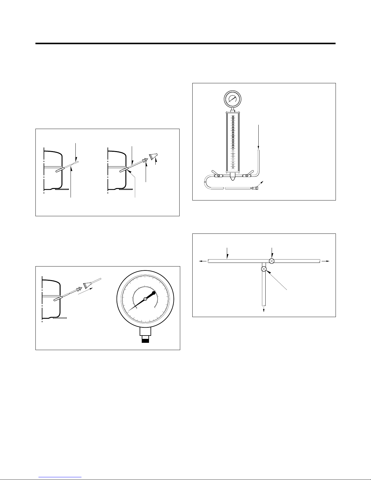
Air Recharging in Compressor
Test the refrigeration by connecting it electrically before
refilling operation. It is necessary to ascertain the function
of the motor-compressor and identify the defects
immediately. If the defects have been found, empty the old
system of eventual R-134a residue by breaking off the end
of the extension piece at its narrow point. (Figure 1)
Replace the filter and any damaged components. Unsolder
and pull off the piece remaining inside the service tube and
then attach an extension completely with male Hansen and
last, solder it to the same tube again. (Figure 2)
It is necessary to execute the soldering operation with
valve open so that the fumes caused by oil residue can
come out freely without blowholes between two tubes
during heating the point to be soldered.
The extension fitted with the male Hansen is connected to
the female fitting of the vacuum pump tube. (Figure 3)
Air evacuating from the system begins so soon as the
pump starts. The refrigeration system must be kept under
vacuum until the reading on the low-pressure gauge
indicates vacuum (0 absolute, -1 atm., -760 mm hg) in any
case it is advisable to keep the pump running for about 60
minutes. (Figure 3)
In case that a considerable leakage occurs and to stop the
vacuum pump will be necessary and add a small quantity
of Freon to the system, if vacuum should not be obtained
(pressure gauge can't fall to 1 atmosphere), start the
refrigeration unit and find the leakage with the special leakfinder. When the defective soldering point is visible, re-do it
after opening the extension tube valve and reestablishing
the normal outside pressure inside the group.
Because the melted alloy is sucked into the tubes and
block them, the pressure must be rebalanced when
vacuum is in the system in soldering. As soon as the
vacuum operation is over, add the quantity in grams of
R-134a to the refrigerant system. Remember that every
system has an exact quantity of R-134a with a tolerance of
±5 grams that can be added. (Figure 4)
Before performing this operation (if the vacuum pump and
refilling cylinder are connected), make sure that the valve
placed between the vacuum pump and refilling tube are
closed to keep the Freon for adding to the system. (Figure 5)
In addition, check the graduated scale on the cylinder for
the quantity of R-134a to be added, for example, if we
have 750 grams of Freon in the cylinder and must add 165
grams to the group, this amount will be reached when
R-134a has dropped to 585 grams, remembering that the
indicator shows a lower limit of meniscus. Do this after
choosing the scale corresponding to the gas pressure
different scales reported as the same gas pressure
indicated by the pressure gauge on the top of the column.
To make R-134a flow into the system, open the valve
placed at the base of the cylinder and connected to the
filling tube. The amount of Freon cannot be added to the
system all at once because it may cause a blocking of
motor-compressor. Therefore, proceed by adding original
quantity of about 20-30 grams and close the valve
immediately.
The pressure rises and the motor-compressor must start,
sucking the gas and making the pressure go down again.
Regulate the valve again, maintaining the same manner
until reaching to the quantity of R-134a established for the
system being charged. When the system is running, the
suction pressure must be stabilized between 0.10 to 0.4
atmosphere.
SERVICING PRECAUTIONS
- 3 -
POINT TO BE
BROKEN
CHARGE TUBE
EXTENSION
FEMALE
HANSEN
MALE HANSEN
SOLDERING POINTSERVICE TUBE EXTENSION
Figure 1 Figure 2
TO THE VACUUM
PUMP
PRESSURE
GAUGE
Figure 3
TO THE R-134a CYLINDER
TO THE REFRIGERATION
SYSTEM
Figure 4
FILLING OR
CHARGE TUBE
VALVE TO BE OPENED
WHEN REFILLING
VALVE TO BE CLOSED
AFTER VACUUM
TO THE VACUUM PUMP
TO THE REFRIGERATION
SYSTEM
TO THE CHARGE
CYLINDER
Figure 5
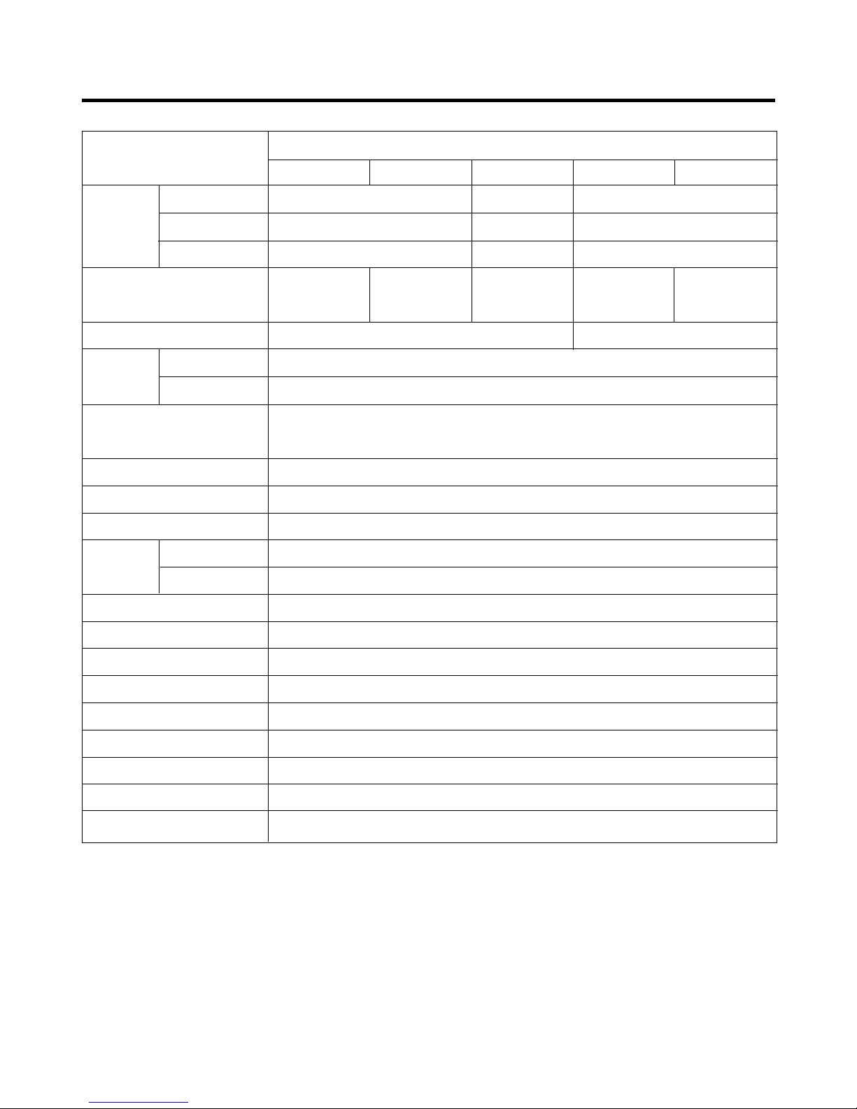
1. SPECIFICATIONS
- 4 -
ITEMS
SPECIFICATIONS
GR-R712/S712
GR-R712A(B) / S712A(B)
GR-712 GR-712P GR-712A(B)*P
FREEZER 158 154 158
NET CAPACITY
REFRIGERATOR 408 396 408
TOTAL 566 550 566
DIMENSIONS (mm)
860(W) X 745(D) X 1794(H) 860(W) X 729(D)
X 1794(H) 860(W) X 745(D) X 1794(H) 860(W)
X 745(D) X 1794(H) 860(W)
X 729(D) X 1794(H)
(Without Handle) (Without Handle)
NET WEIGHT (kg) 97 96
FREEZER Knob Dial
REFRIGERATOR Micom Control
DEFROSTING SYSTEM
Full Automatic
Heater Defrost
OUT CASE Pre Coated Metal
INNER CASE A B S
INSULATION Cyclo-Pentane Foam
FREEZER 1 EA
REFRIGERATOR 2 EA
VEGETABLE TRAY Drawer Type
EGG TRAY 1 Piece (*2)
ICE TRAY 1 Piece (*2)
ICE BANK 1 Piece
COMPRESSOR P.T.C Starting Type
EVAPORATOR Fin Tube Type
CONDENSER Wire Condenser
REFRIGERANT R134a (140g)
DEFROSTING DEVICE
Heater
( l )
TEMPERA TURE
CONTROL
SHELF
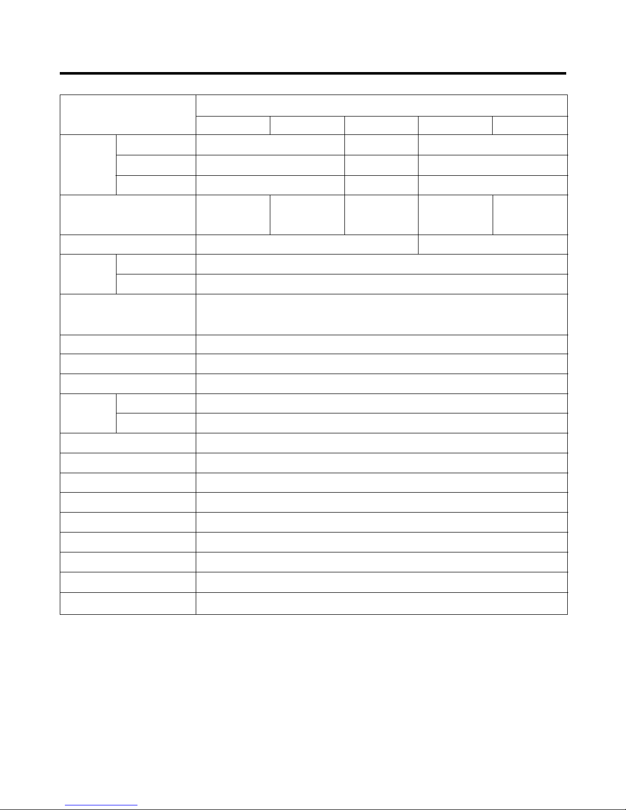
- 5 -
ITEMS
SPECIFICATIONS
GR-R652/S652
GR-R652A(B) / S652A(B)
GR-652 GR-652P GR-652A(B)*P
FREEZER 158 146 150
NET CAPACITY
REFRIGERATOR 388 378 388
TOTAL 538 524 538
DIMENSIONS (mm)
860(W) X 725(D)
X 1794(H) 860(W) X 709(D) X 1794(H) 860(W)
X 725(D) X
1794(H) 860(W) X 725(D) X 1794(H) 860(W) X
709(D) X 1794(H)
(Without Handle) (Without Handle)
NET WEIGHT (kg) 95 94
FREEZER Knob Dial
REFRIGERATOR Micom Control
Full Automatic
Heater Defrost
OUT CASE Pre Coated Metal
INNER CASE A B S
INSULATION Cyclo-Pentane Foam
FREEZER 1 EA
REFRIGERATOR 2 EA
VEGETABLE TRAY Drawer Type
EGG TRAY 1 Piece (*2)
ICE TRAY 1 Piece (*2)
ICE BANK 1 Piece
COMPRESSOR P.T.C Starting Type
EVAPORATOR Fin Tube Type
CONDENSER Wire Condenser
REFRIGERANT R134a (140g)
DEFROSTING DEVICE
Heater
( l )
SHELF
DEFROSTING SYSTEM
TEMPERA TURE
CONTROL
2-1. FEATURE CHART
uu
GR-R652/712, S652/712
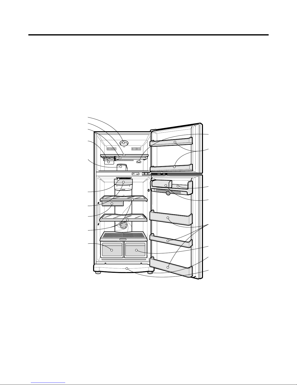
2. PARTS IDENTIFICATION
- 6 -
NOTE: This guide covers several different models.The refrigerator you have
purchased may have some or all of the features shown above.
Egg Storage Rack
Dairy Conner
Refrigerator
Door Rack
Freezer Door Rack
Leveling Screw
Vegetable Drawer
Base Cover
FREEZER
COMPARTMENT
Lamp
Shelf
Extra Shelf
(Optional)
Deodorizer
(Optional)
Vitamin
Vegetable Drawer
(Optional)
Shelves
Lamp
Fresh Zone
(Optional)
REFRIGERATOR
COMPARTMENT
Freezer Temperature
Control Dial
Twisting Ice
Serve (Optional)
or
General Type
Ice Making
(Optional)
uu
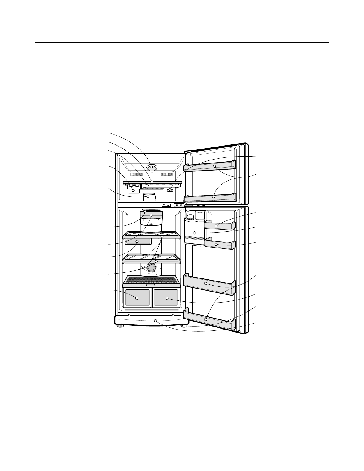
GR-652/712P
- 7 -
Egg Storage Rack
Water Dispenser
Utility Corner
Refrigerator
Door Rack
Freezer Door Rack
Leveling Screw
Base Cover
FREEZER
COMPARTMENT
Lamp
Shelf
Deodorizer
(Optional)
Vitamin
Vegetable Drawer
(Optional)
Vegetable Drawer
Shelves
Lamp
Fresh Zone
(Optional)
REFRIGERATOR
COMPARTMENT
Freezer Temperature
Control Dial
Twisting Ice
Serve (Optional)
or
General Type
Ice Making
(Optional)
Extra Shelf
(Optional)
NOTE: This guide covers several different models.The refrigerator you have
purchased may have some or all of the features shown above.
uu
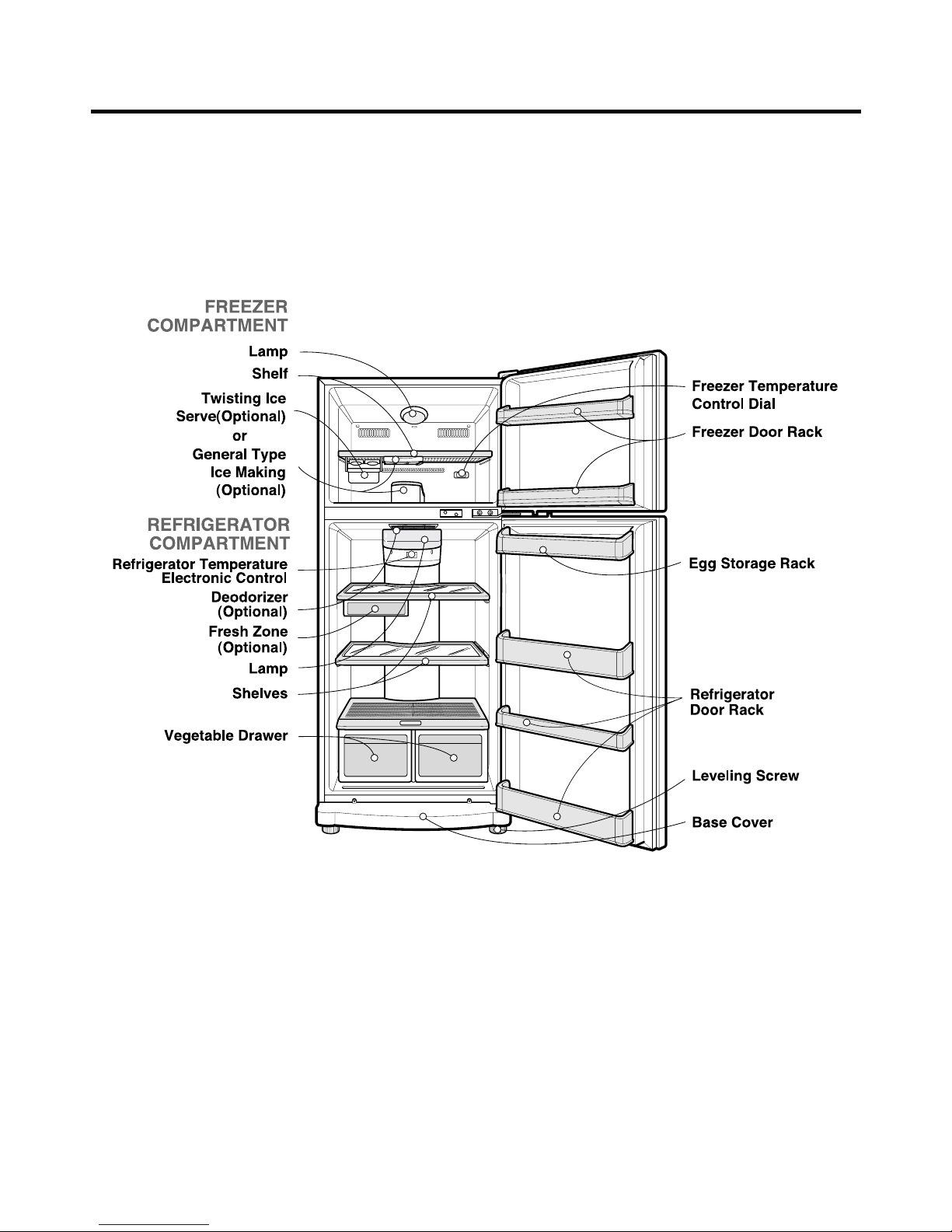
GR-652/712
- 8 -
NOTE: This guide covers several different models.The refrigerator you have
purchased may have some or all of the features shown above.
- 9 -
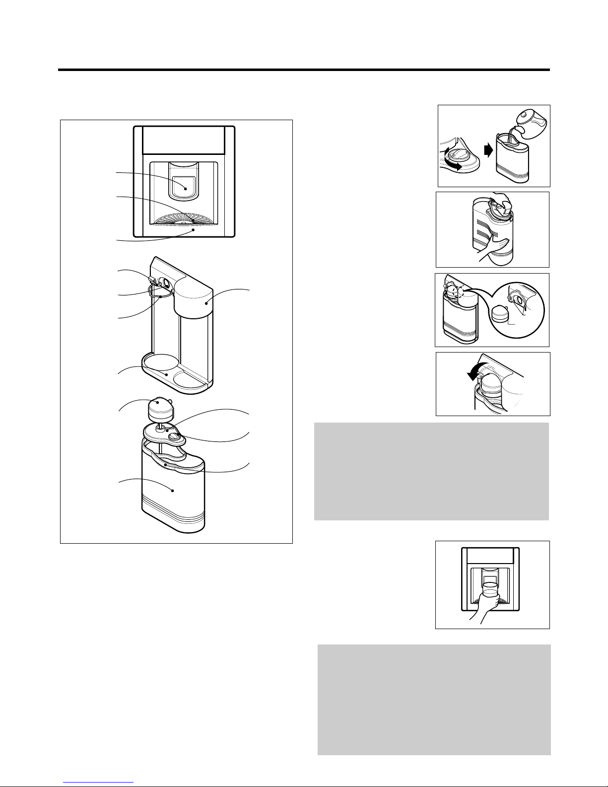
2-2 WATER DISPENSER
● Features
● Putting The Water In The Water Tank
1. Turn the lock dial in the
direction of the arrow as
shown to remove it and
pour water into the
dispenser water tank.
2. Close the cap by tilting it
and putting one side in first
and then the other side as
shown.
3. Place the water tank in the
tank holder inside the
refrigerator. Make sure that
the groove on the connecting
part is in position with the
tab. Push the connecting part
into the hole until it "Clicks".
4. Fix the connecting part in
place by means of the
holder ring as shown.
● Drinking
1 Press the dispenser pad
with the glass.
2 The water is released when
the dispenser pad is
pressed. The pad returns
to its original position when
the glass is removed, and
the water stops its flow.
Tab
Groove
CONNECTING
PART
WATER TANK
LOCK DIAL
CAP
HANDLE
TAB
HOLE
HOLDER RING
BOTTLE
HOLDER
MOTOR
(INSIDE)
DISPENSER
GRILLE
DRIP TRAY
PAD
WATER TANK
CAUTION
1. Do not use anything other than water including soft
drinks, milk and juices.
2. Hot water needs to be cooled before being put in the
water tank.
3. Always use the holder ring to fix the water tank in place
to prevent the tank from moving or getting loose.
NOTE
1. The lamp is lit when the dispenser pad is pressed
and the water is released. This makes it possible to
see the water level in the dark.
2. The motor rotates in reverse for a few seconds after
the dispenser is released to dispose of any water
remaining in the tubes. (This may cause the sound
of water being sucked back inside)
- 10 -
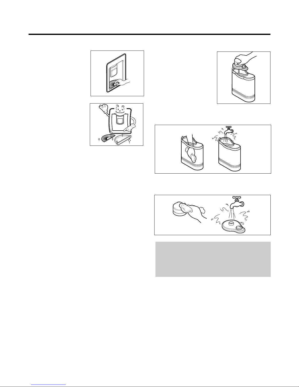
● Cleaning
Grille and Drip Tray
1. Pull the drip tray out and
remove with the grille.
2. Dispose of the water in the
kitchen sink, wash the drip
tray and the grille with a
mild detergent and rinse
thoroughly.
Water Tank
1. Remove the cap.
2. Clean the inside and outside of the water tank with
dishwashing detergent and rinset horoughly under
running water.
Other Parts
Remove the cap and, clean the cap and connecting part
with a mild detergent and rinse thoroughly.
CAUTION
1. Use lukewarm water when cleaning.
2. Do not use anything other than water. If it is used with
soft drinks, put water in the water tank and discharge
three or four cups of water shortly.
3-1 DOOR
● Freezer Door
1. Remove the hinge cover by pulling it upwards.
2. Loosen hexagonal bolts fixing the upper hinge to the
body and lift the freezer door.
3. Pull out the door gasket to remove from the door foam
Ass'y.
● Refrigerator Door
1. Loosen hexagonal bolts fixing the lower hinge to the
body to remove the refrigerator door only.
2. Pull out the door gasket to remove from the door foam
Ass'y.
3-2 DOOR SWITCH
1. To remove the door switch, pull out it with a '—' type
driver as shown in (figure 9).
2. Disconnect the lead wire from the switch.
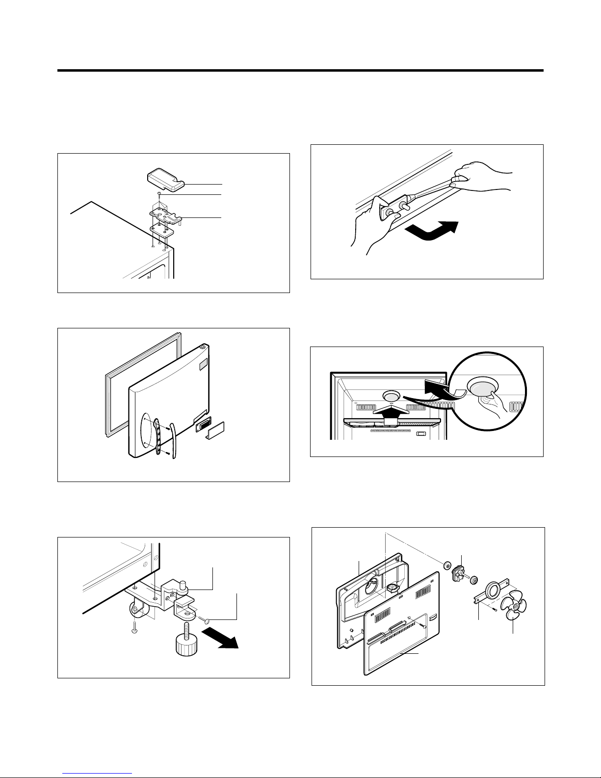
3-3 FAN AND FAN MOTOR
1. Remove the freezer shelf.
2. Remove the Cover Lamp-F and Case Lamp by
loosening 1 screw fixed to ceiling of Inner Case.
3. Remove the Grille by pulling it out.
4. Pull out the Shroud and remove the Fan Motor Assy by
loosening 2 screws.
5. Pull out the fan and, separate the Fan Motor, Brackets
and the Guide Fan.
3. DISASSEMBLY
- 11 -
BOLT
HINGE
HINGE COVER
Figure 6
Figure 7
LOWER HINGE
BOLT
Figure 8
Figure 9
GUIDE FAN
FAN
SHROUD
GRILLE
FAN MOTOR
Figure 12
Figure 11
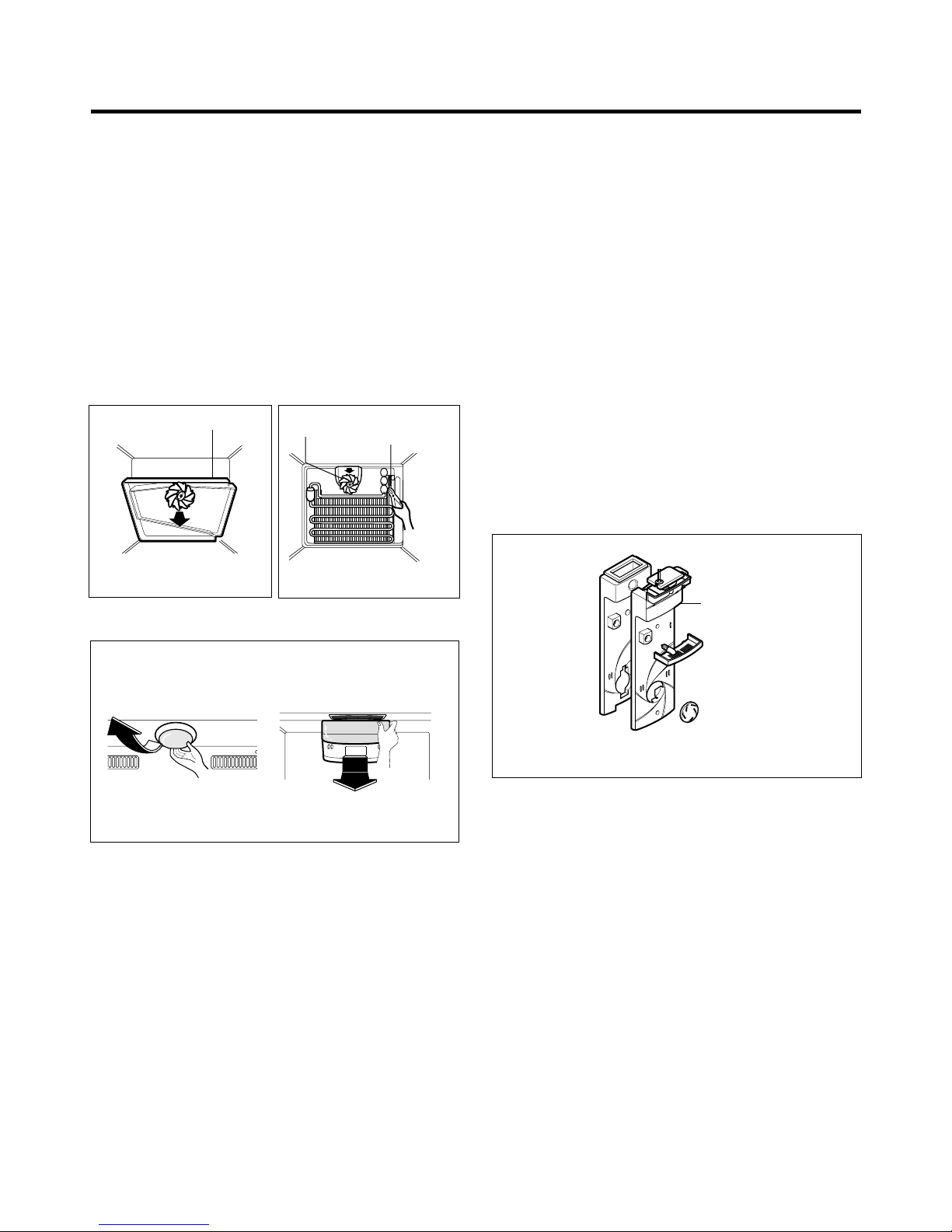
3-4 DEF' CONTROL ASSY
Def control ASM consists of Defrost Sensor and FUSE–M.
Defrost
Sensor
functions to defrost automatically and it is
attached to the Evaporator and the metal side of the case
senses Temp.
Fuse-M is a kind of safety device for preventing overheating of the Heater when defrosting.
At the temperature of 72°C, it stops the emission of TEMP
from the Defrost Heater.
1. Pull out the shroud-F after removing the Grille Fan.
(Figure 13)
2. Separate the connectors connected with the Def Control
ASM and replace the Def Control ASM after cutting the
Tie Wrap. (Figure 14)
3-5 LAMP
3-5-1 Freezer room lamp
1. Unplug the power cord from the outlet.
2. Remove the room lamp lid by taking down while pulling
it forward with your hand after inserting finger into the
inside hole as shown in (figure 16).
3. Remove the lamp by turning it counterclockwise.
4. Assemble in reverse order of disassembly. Replacement
bulb must be the same specication as original.
3-5-2 Refrigerator room lamp
1. Unplug the power cord from the outlet.
2. Remove refrigerator shelves.
3. Remove the room lamp lid by taking down while pulling
forward with your hands as shown in (figure 17).
4. Turn the lamp counterclockwise.
5. Assemble in reverse order of disassembly. Replacement
bulb must be the same specification as original.
3-6 CONTROL BOX-R
1. First, remove all shelves in the refrigerator and Control
Box-R by loosening 1 screw.
2. Loosen 2 screws fixing the Control Box-R to the Inner
Case after detaching the cap screw.
3. Remove the Control Box-R by pulling it downward.
- 12 -
SHROUD-F
Figure 13
FAN
DEF CONTROL ASM
Figure 14
FREEZER ROOM LAMP REFRIGERATOR ROOM LAMP
Figure 16
Figure 17
MULTI FLOW
DUCT
Figure 18
4-1 COMPRESSOR
4-1-1 Role
The compressor inhales low temperature and low pressure
gas evaporated from Evaporator of the Refrigerator, and
condenses this gas to high temperature and high pressure
gas, and then plays delivering role to Condenser.
4-1-2 Composition
The Compressor is Composed of Compressor Apparatus
compressing gas, Compressor Motor moving Compressor
Apparatus and Case protecting Compressor Apparatus
and Motor. There are PTC-Starter, and Over Load
Protector (OLP) in the Compressor outside.
On the other
hand, because the Compressor consists of 1/1000mm processing
precision components and is sealed after producing without dust
or humidity, deal and repair with care.
4-1-3 Note to Use
(1) Be careful not to allow over-voltage and over-current.
(2) No Strike
If applying forcible power or strike (dropping or careless
dealing), poor operation and noise may occur.
(3) Use proper electric components appropriate to the
Compressor.
(4) Note to Keep Compressor.
If Compressor gets wet in the rain and rust in the pin of
Hermetic Terminal, poor operation and poor contact
may cause.
(5) Be careful that dust, humidity, and flux due to welding
don't inflow in Compressor inside in replacing
Compressor. Dust, humidity, and flux due to welding
which inflows to Cylinder may cause lock and noise.
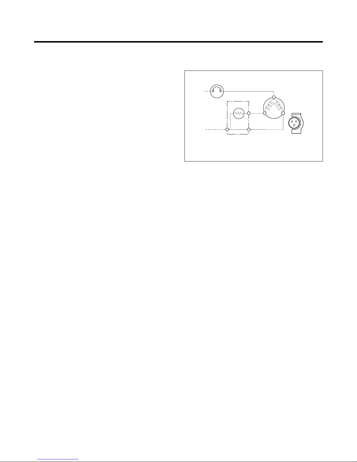
4-2 PTC-STARTER
4-2-1 Composition of PTC-Starter
(1) PTC (Positive Temperature Coefficient) is no-contact
semiconductor starting device which uses ceramic
material and the material consists of BaTiO
3.
(2) The higher the temperature is, the higher resistance
value becomes . These features are used as starting
device of Motor.
4-2-2 Role of PTC-Starter
(1) PTC is attached to Hermetic Compressor used for
Refrigerator, Show Case and starts Motor.
(2) Compressor for household refrigerator applies single-
phase induction Motor.
For normal operation of single-phase induction motor, in
the starting operation flows in both main coil and subcoil. After the starting is over, the current is cut off in
subcoil. The proper features of PTC play the above all
roles. So, PTC is used as a starting device of motor.
4-2-3 PTC-Applied Circuit Diagram
● According to Starting Method of Motor
4-2-4 Motor Restarting and PTC Cooling
(1) For restarting after power off during normal
Compressor Motor operation, plug the power cord after
5 min. for pressure balance of Refrigerating Cycle and
PTC cooling.
(2) During normal operation of Compressor Motor, PTC
elements generate heat continuously. Therefore,
if PTC isn't cooled for a while after power off, Motor
can't operate again.
4-2-5 Relation of PTC-Starter and OLP
(1) If power off during operation of Compressor and power
on before PTC is cooled, (instant shut-off within 2 min.
or reconnect a power plug due to misconnecting),
PTC isn't cooled and a resistance value grows. As a
result, current can't flow to the sub-coil and Motor can't
operate and OLP operates by flowing over current in
only main-coil.
(2) While the OLP repeats on and off operation about 3-5
times, PTC is cooled and Compressor Motor performs
normal operation.
If OLP doesn't operate when PTC is not cooled,
Compressor Motor is worn away and causes circuitshort and fire. Therefore, use a proper fixed OLP
without fail.
4-2-6 Note to Use PTC-Starter
(1) Be careful not to allow over-voltage and over-current.
(2) No Strike
Don't apply a forcible power or strike.
(3) Keep apart from any liquid.
If liquid such as oil or water inflows into PTC,
PTC materials it may break due to insulation
breakdown of material itself.
(4) Don't change PTC at your convenience.
Don't disassemble PTC and mold. If damaging to
outside of PTC-starter, resistance value alters and poor
starting of compressor motor may cause.
(5) Use a properly fixed PTC.
4. ADJUSTMENT
- 13 -
PTC STARTER
HERMETIC
TERMINAL
COMPRESSOR
MOTOR
C
M
S
M
3
6
5
S
PTC
OVERLOAD PROTECTOR
RSIR
Figure 20
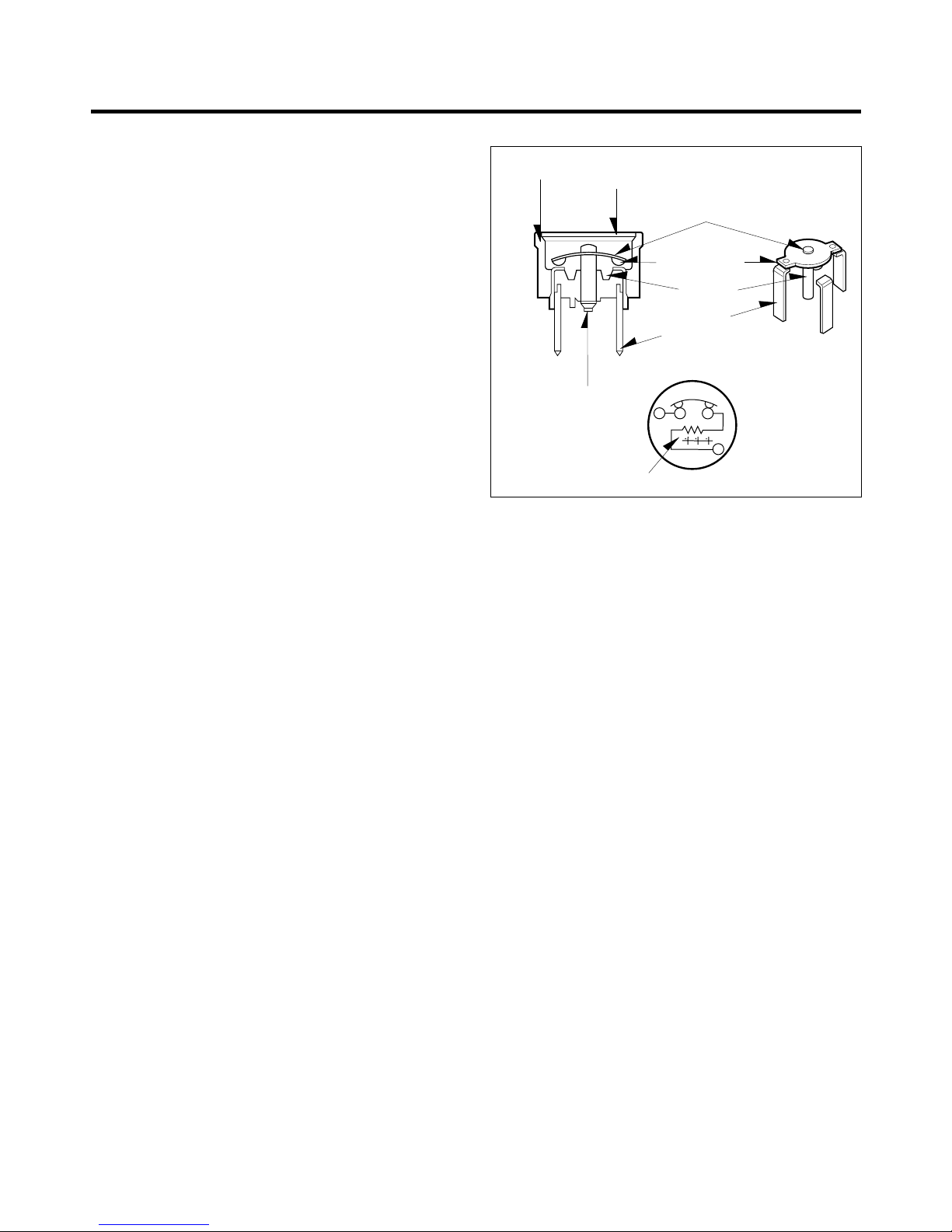
4-3 OLP (OVER LOAD PROTECTOR)
4-3-1 Definition of OLP
(1) OLP (OVER LOAD PROTECTOR) is attached to
Hermetic Compressor and protects Motor by cutting off
current in Compressor Motor by Bimetal in the OLP in
case of over-rising temperature.
(2) When over-voltage flows to Compressor motor, Bimetal
works by heating the heater inside OLP,
and OLP protects Motor by cutting off current which
flows to Compressor Motor.
4-3-2 Role of OLP
(1) OLP is attached to Hermetic Compressor used to
Refrigerator and Show Case and prevents Motor Coil
from being started in the Compressor.
(2) Do not turn the Adjust Screw of OLP in any way for
normal operation of OLP.
(Composition and connection Diagram of OLP)
- 14 -
CONTACTING
POINT
COVER
BIMETAL
CONTACTING
POINT
HEATER
TERMINALS
ADJUST
SCREW
HEATER
BIMETAL
Figure 21
uu
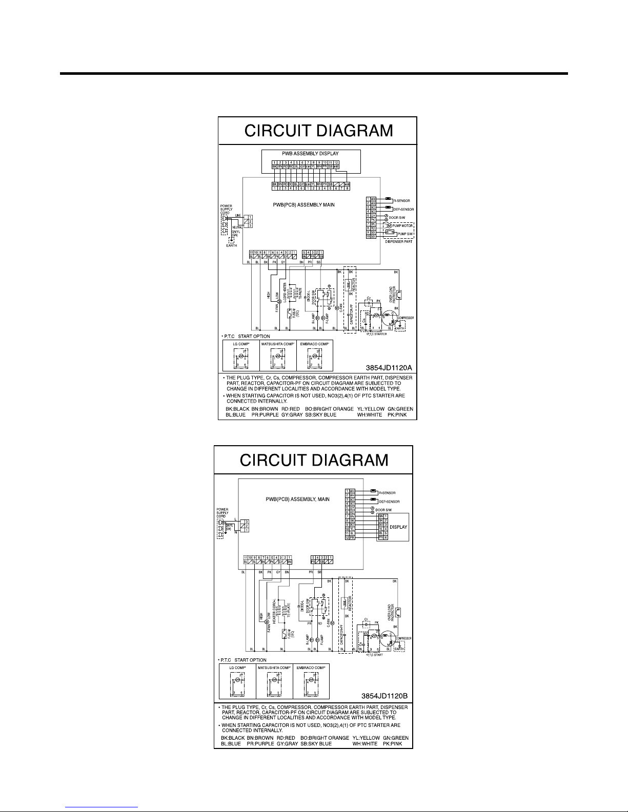
GR-R652/R712, S652/S712, 652P/712P
uu
GR-652/712
NOTE : 1. This is a basic diagram and specifications vary in different localities.
5. CIRCUIT DIAGRAM
- 15 -
 Loading...