

Page 1

Room Air Conditioner
SVC MANUAL(Exploded View)
MODEL : LP6000ER
LP7000R
CAUTION
Before Servicing the unit, read the safety precautions in General SVC manual.
Only for authorized service personnel.
Internal Use Only
http://biz.lgservice.com
WEBSITE http://biz.LGservice.com
E-MAIL http://www.LGEservice.com/techsup.html
Page 2

A20190H
CONTENTS
1. PREFACE
1.1 SAFETY PRECAUTIONS................................2
1.2 INSULATION RESISTANCE TEST .................2
1.3 SPECIFICATIONS...........................................3
1.4 FEATURES......................................................4
1.5 CONTROL LOCATIONS .................................4
2.
DISASSEMBLY INSTRUCTIONS
2.1 MECHANICAL PARTS ....................................5
2.1.1 FRONT GRILLE .....................................5
2.1.2 TOP COVER ..........................................5
2.1.3 CABINET ................................................5
2.1.4 CONTROL BOX .....................................5
2.2 AIR HANDLING PARTS ..................................6
2.2.1 AIR GUIDE AND CROSS FLOW FAN ...6
2.2.2 FAN AND SHROUD ...............................6
2.2.3 INDOOR FAN MOTOR...........................7
2.2.4 AIR GUIDE LOWER ...............................7
2.3 ELECTRICAL PARTS......................................7
2.3.1 OVERLOAD PROTECTOR ....................7
2.3.2 COMPRESSOR......................................8
2.3.3 CAPACITOR...........................................8
2.3.4 POWER CORD ......................................8
2.3.5 OUTDOOR MOTOR...............................9
2.4 REFRIGERATION CYCLE ..............................9
2.4.1 CONDENSER.........................................9
2.4.2 EVAPORATOR.......................................9
2.4.3 CAPILLARY TUBE .................................9
3.
INSTALLATION
3.1 HOW TO INSTALL THE UNIT.......................12
3.2 CHECKING INSTALLATION .........................12
3.3 WINDOW REQUIREMENTS .........................12
3.4 INSTALLATION KITS CONTENTS ...............13
3.5 SUGGESTED TOOL REQUIREMENTS .......13
3.6 HOW TO INSTALL ........................................13
3.7 REMOVAL FROM WINDOW.........................16
4.
TROUBLESHOOTING GUIDE
4.1 OUTSIDE DIMENSIONS ...............................16
4.2 PIPING SYSTEM...........................................17
4.3 TROUBLESHOOTING GUIDE ......................18
5. SCHEMATIC DIAGRAM
5.1 CIRCUIT DIAGRAM ......................................27
5.2 ELECTRONIC CONTROL DEVICE...............28
5.3
COMPONENTS LOCATION(FOR AC P.C.B ASM)
5.4
COMPONENTS LOCATION(FOR DC P.C.B ASM)
...
..29
29
6. EXPLODED VIEW ..................................30
1. PREFACE
This
SERVICE MANUAL provides various service information, including the mechanical and electrical
parts etc. This room air conditioner was manufactured and assembled under a strict quality control system.
The refrigerant is charged at the factory. Be sure to read the safety precautions prior to servicing the unit.
1.1 SAFETY PRECAUTIONS
1. When servicing the unit, set the ROTARY SWITCH
or POWER SWITCH to OFF and unplug the power
cord.
2. Observe the original lead dress.
If a short circuit is found, replace all parts which
have been overheated or damaged by the short
circuit.
3. After servicing the unit, make an insulation resistance test to protect the customer from being
exposed to shock hazards.
Copyright ©2008 LG Electronics. Inc. All right reserved.
Only for training and service purposes
1.2
INSULATION RESISTANCE TEST
1. Unplug the power cord and connect a jumper
between 2 pins (black and white).
2. The grounding conductor (green) is to be open.
3. Measure the resistance value with an ohm meter
between the jumpered lead and each exposed
metallic part on the equipment at all the positions
(except OFF) of the ROTARY SWITCH.
4. The value should be over 1MΩ.
- 2 -
LGE Internal Use Only
Page 3
1.3 SPECIFICATIONS
1.3.1 FOR LP6000ER/LP7000R
MODELS
ITEMS
POWER SUPPLY
COOLING CAPACITY (Btu/h)
INPUT (W)
RUNNING CURRENT (A)
E.E.R (BTU/W.h)
OPERATING
CONDITION
REFRIGERANT (R-22) CHARGE
EVAPORATOR
CONDENSER
FAN, INDOOR
FAN, OUTDOOR
FAN SPEEDS, FAN/COOLING
FAN MOTOR
OPERATION CONTROL
INDOOR (°C)
OUTDOOR (°C)
LP6000ER LP7000R
115V, 60Hz
6,000 7,000
560 700
5.2 6.5
10.7 10.0
26.7(DB)* 19.4(WB)**
35(DB)* 23.9(WB)**
435g(15.3 oz) 350g(12.3 oz)
2 ROW 9 STACKS, SLIT FIN TYPE
2 ROW 14 STACKS, LOUVER FIN TYPE
CROSS FLOW FAN
AXIAL FAN
3/3
4 POLES
REMOTE CONTROLLER
ROOM TEMP. CONTROL
AIR DIRECTION CONTROL
CONSTRUCTION
PROTECTOR
POWER CORD
DRAIN SYSTEM
NET WEIGHT (lbs/kg)
OUTSIDE DIMENSION (inch)
(W x H x D) (mm)
* DB:Dry Bulb
**
WB:Wet Bulb
COMPRESSOR
FAN MOTOR
THERMISTOR
VERTICAL LOUVER (RIGHT & LEFT)
HORIZONTAL LOUVER (UP & DOWN)
TOP-DOWN CHASSIS
OVERLOAD PROTECTOR
INTERNAL THERMAL PROTECTOR
3 WIRE WITH GROUNDING
ATTACHMENT PLUG (CORD-CONNECTED TYPE)
DRAIN PIPE SPLASHED BY FAN SLINGER
55/25 57/26
235/8 x 12 x 181/32
600 x 305 x 458
Copyright ©2008 LG Electronics. Inc. All right reserved.
Only for training and service purposes
- 3 -
LGE Internal Use Only
Page 4
1.4 FEATURES
Timer
Air
Purifier
AIR
PURIFIER
Power
Temp
Timer Mode
Auto
Swing
Fan Speed
1
5
2
4
3
52 4
31 6
6
5
4
3
2
1
• Designed for COOLING ONLY.
• Powerful and quiet cooling.
• Simple installation and service.
• Low air-intake, top cool-air discharge.
• Built-in adjustable THERMISTOR
• Washable one-touch filter
• Compact size
• Reliable and efficient rotary compressor.
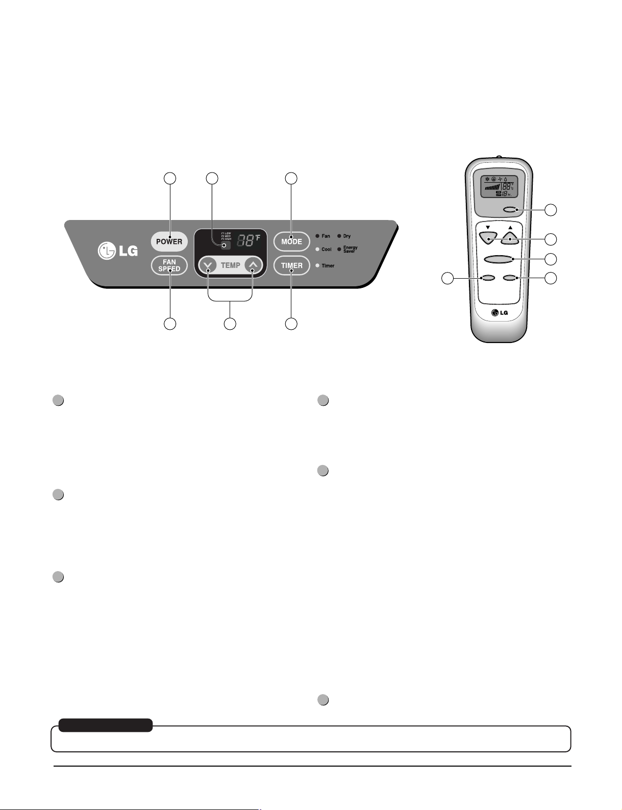
1.5 CONTROL LOCATIONS
Precaution: The Remote Control unit will not function properly if bright light strikes the sensor window of the air
conditioner or if there are obstacles between the Remote Control unit and the air conditioner.
POWER
• To turn the air conditioner ON, push this button. To
turn the air conditioner OFF, push the button again.
• This button takes priority over any other button.
FAN SPEED
• Every time you push this button, it advances the
setting as follows: {High(F3) → Low(F1) → Med(F2)
→ High(F3)}
• When you first turn it on, the unit is in cool mode,
high fan speed, temperature setting at 72˚F.
TIMER
- SHUT-OFF TIME
TEMPERATURE SETTING
• Use this button to automatically control the
temperature of the room.
The temperature can be set within a range of 60°F
to 86°F by increments of 1°F.
• You will usually use shut-off time while you sleep.
• With unit running, use Timer to set number of hours
until shut-off.
• For your sleeping comfort, once Time is set, the
Temperature setting will raise 2°F after 30 min, and
2°F after another 30 min.
MODE
- Every time you push this button, it will cycle through
COOL, ENERGY SAVER, FAN and DRY.
- ENERGY SAVER
• The fan stops when the compressor stops cooling.
Approximately every 3 minutes the fan will turn on
and the unit will check the room air to determine if
cooling is needed.
• Every time you push Timer button, it advances the
Timer setting as follows: 1 Hour → 2 Hours → etc. →
12 Hours maximum.
- START TIME
• While unit not running, use timer to set number of
hours before unit starts.
• Every time you push Timer button, it advances the
Timer setting as follows: 1 Hour → 2 Hours → etc. →
12 Hours maximum.
REMOTE CONTROL SENSOR
AUTO RESTART
When power is restored after an electrical power failure, the unit will begin to run at its last setting.
Copyright ©2008 LG Electronics. Inc. All right reserved.
Only for training and service purposes
- 4 -
LGE Internal Use Only
Page 5
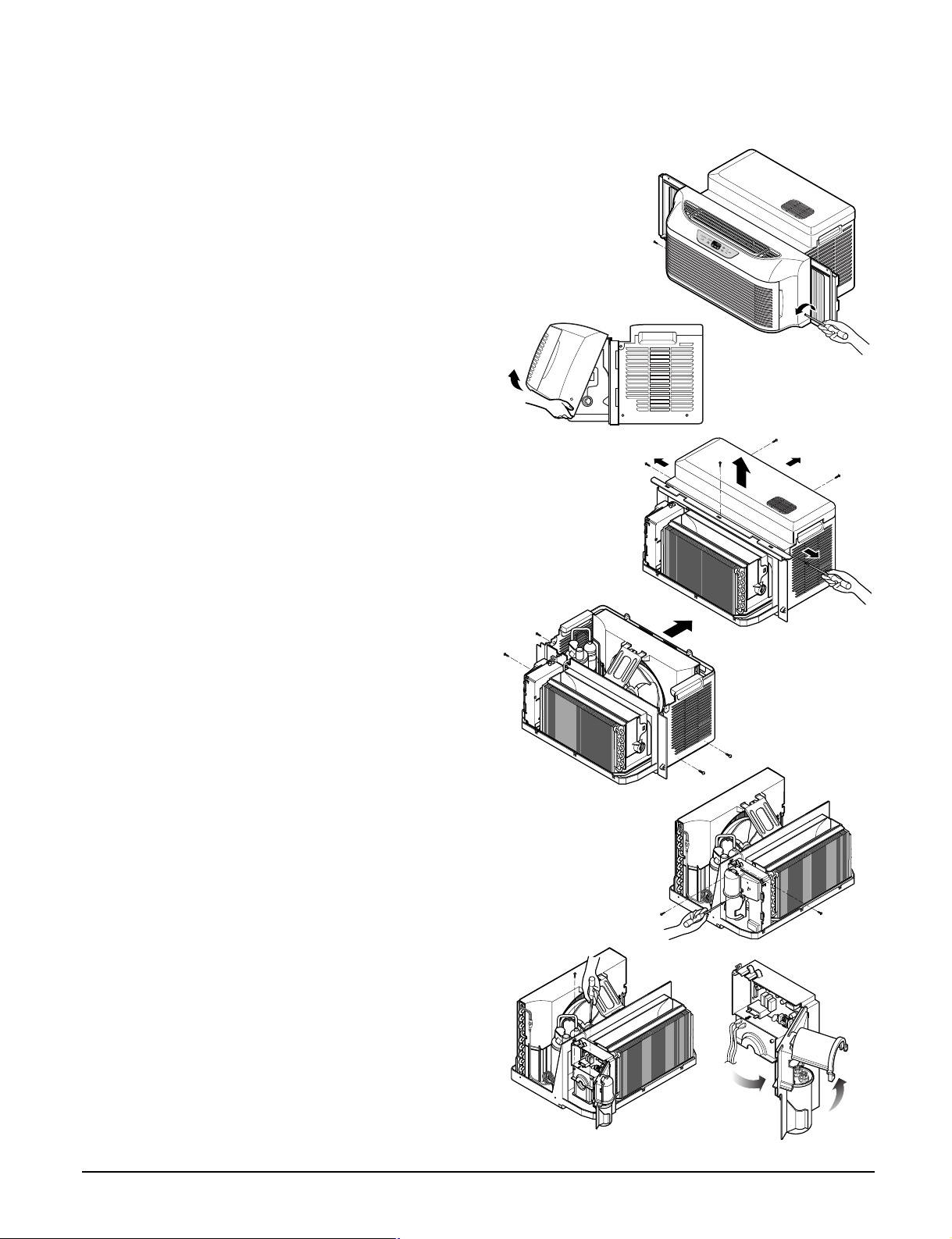
2. DISASSEMBLY INSTRUCTIONS
2.1 MECHANICAL PARTS
2.1.1 FRONT GRILLE
1. Unplug the unit from source of power.
2. Remove the 2 screws securing the front
Grille.(See Figure 1)
3. Push the grille up from the bottom and pull the
top of the grille way from the cabinet to lift the
top tabs out of their slots.(See Figure 2)
4. Disconnect display connector.
2.1.2 TOP COVER
1. Disconnect the unit from the power source.
2. Remove the front grille.(Refer to section 2.1.1)
3. Remove curtains on both side.
4. Remove 5 screws that secure the top cover to
the cabinet.(See Figure 3)
2.1.3 CABINET
1. Disconnect the unit from the power source.
2. Remove the front grille. (Refer to section 2.1.1)
3. Remove the top cover. (Refer to section 2.1.2)
4. Remove 4 screws that secure the cabinet to the
base pan. (See Figure 4)
5. Remove the cabinet.
6. Re-install by referring to the procedures above.
Figure 1
Figure 2
Figure 3
Figure 4
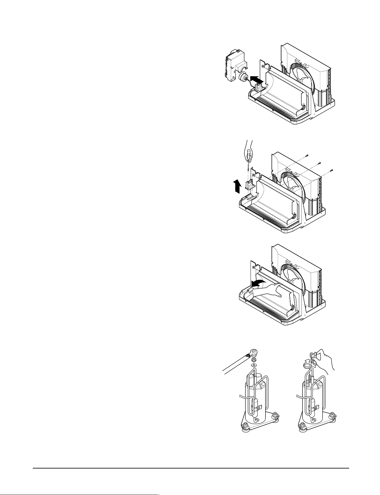
2.1.4 CONTROL BOX
1. Disconnect the unit from the power source.
2. Remove the front grille. (Refer to Section 2.1.1)
3. Remove the screw that fastens the power cord.
4. Remove the grounding screw from the
evaporator channel and remove the thermistor
from the evaporator fin.
5. Remove the 2 screws that fasten the control
box cover and open the control box cover.(See
Figure 5)
6. Remove the housing that connects motor and
wires come form compressor.
7. Remove the screw that secures the control box
and base pan.
8. Remove the 2 screws that secure the control
box and motor mount.(See Figure 6)
9. Move the control box upward.
Figure 5
Figure 6
Copyright ©2008 LG Electronics. Inc. All right reserved.
Only for training and service purposes
- 5 -
LGE Internal Use Only
Page 6
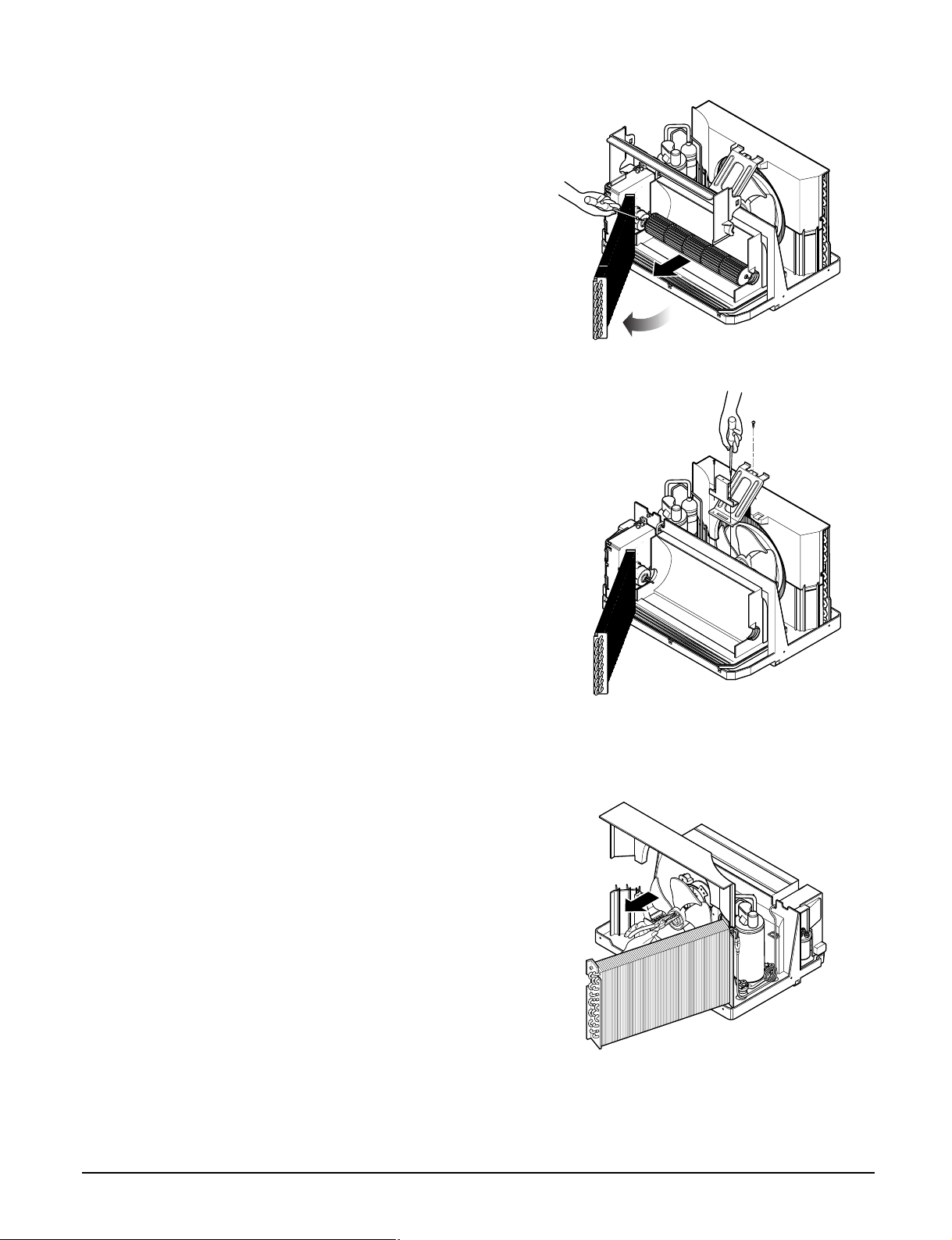
2.2 AIR HANDLING PARTS
2.2.1 AIR GUIDE UPPER AND CROSS
FLOW FAN
1. Disconnect the unit from the power source.
2. Remove the front grille.
(Refer to Section 2.1.1)
3. Remove the top cover. (Refer to Section 2.1.2)
4. Remove the cabinet. (Refer to Section 2.1.3)
5. Remove the control box. (Refer to Section
2.1.4)
6. Move the evaporator forward, pulling it upward
slightly.
7. Pull the air guide upper and remove it.(See
Figure 7)
8. Loosen the bolt securing the cross flow fan to
the motor (do not remove).
9. Pull the cross flow fan and remove it.
10. Re-install by referring to the procedures
above.
Figure 7
Figure 8
2.2.2 FAN AND SHROUD
1. Disconnect the unit from the power source.
2. Remove the front grille. (Refer to Section 2.1.1)
3. Remove the top cover. (Refer to Section 2.1.2)
4. Remove the cabinet. (Refer to Section 2.1.3)
5. Remove 3 screws which the fasten the brace
and the bracket. (See Figure 8)
6. Remove the brace and the bracket.
7. Remove 4 screws which fasten the condenser
channel, shroud and base pan.
8. Move the shroud upward and remove it.
9. Move the condenser forward, pulling it slightly
upward .
10. Remove the clamp with a hand plier which
secures the fan.(See Figure 9)
11. Remove the fan.
14. Re-install by referring to the procedures
above.
Figure 9
Copyright ©2008 LG Electronics. Inc. All right reserved.
Only for training and service purposes
- 6 -
LGE Internal Use Only
Page 7
2.2.3 INDOOR FAN MOTOR
1. Disconnect the unit from the power source.
2. Remove the front grille. (Refer to Section 2.1.1)
3. Remove the control box.
(Refer to Section 2.1.4)
4. Remove the air guide upper and cross flow fan.
(Refer to Section 2.2.1)
5. Remove the motor.(See Figure 10)
6. Re-install by referring to the procedures above.
2.2.4 AIR GUIDE LOWER
1. Disconnect the unit from the power source.
2. Remove the front grille. (Refer to Section 2.1.1)
3. Remove the top cover. (Refer to Section 2.1.2)
4. Remove the control box.
(Refer to Section 2.1.4)
5. Remove the air guide upper and cross flow fan.
(Refer to Section 2.2.1)
6.
Remove the motor. (Refer to
7.
Remove 2 screws which fasten the mount motor
and remove mount motor. (
8. Remove the fan and shroud.(Refer to Section
2.2.2)
9. Remove 3 screws that secure the air guide to
the base pan. (See Figure 11)
10. Pull the airguide toward youself. (See Figure
12)
11. Re-install by referring to the procedures above.
Section
See Figure 11
2.2.3)
Figure 10
Figure 11
)
Figure 12
2.3 ELECTRICAL PARTS
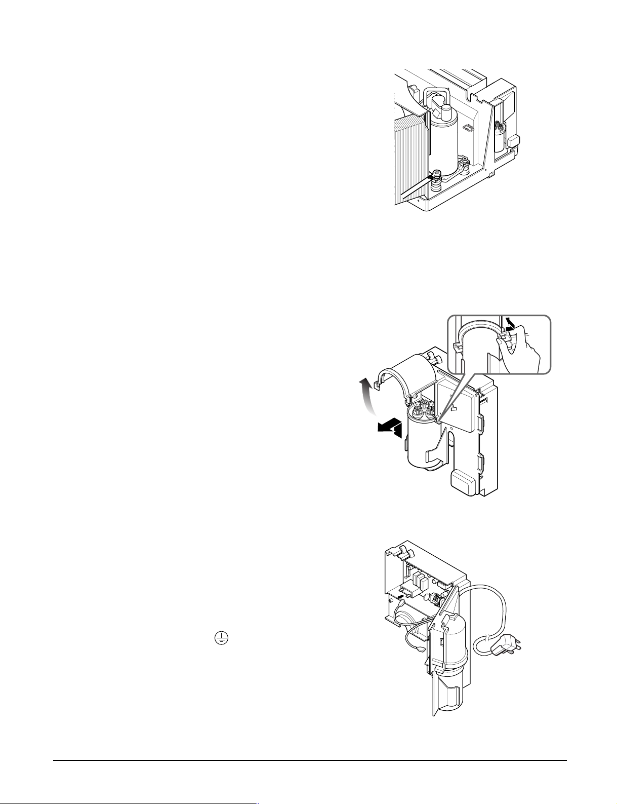
2.3.1 OVERLOAD PROTECTOR
1. Remove the front grille, top cover and cabinet.
(Refer to Section 2.1)
2. Remove the nut which fastens the terminal
cover.
3. Remove the terminal cover.
4. Remove all the leads from the overload
protector.
5. Remove the overload protector.
6. Re-install the components by referring to the
removal procedure above.
(See Figure 13 and 14)
Copyright ©2008 LG Electronics. Inc. All right reserved.
Only for training and service purposes
- 7 -
Figure 13
Figure 14
LGE Internal Use Only
Page 8
2.3.2 COMPRESSOR
1. Remove the front grille, top cover and cabinet.
(Refer to Section 2.1)
2. Discharge the refrigerant system using a
FreonTMRecovery System.
If there is no valve to attach the recovery
system, install one (such as a Watco A-1)
before venting the FreonTM. Leave the valve in
place after servicing the system.
3. Remove the overload protector. (Refer to
section 2.3.1)
4. After purging the unit completely, unbraze the
suction and discharge tubes at the compressor
connections.
5. Remove the 3 nuts and the 3 washers that
fasten the compressor.(See Figure 15)
6. Remove the compressor.
7. Re-install the components by referring to the
removal procedure, above.
2.3.3 CAPACITOR
1. Remove the front grille. (Refer to Section 2.1.1)
2. Open the capacitor cover. (See Figure 16)
3. Remove all the leads of capacitor terminals.
4. Re-install the components by referring to the
removal procedure above.
Figure 15
Figure 16
2.3.4 POWER CORD
1. Remove the control box.(Refer to section 2.1.4)
2. Open the control box cover.
3. Disconnect two leads from the capactitor and
relay.
4. Remove a screw securing the clip with cord to
the control box.
5. Pull out the power cord.
6. Re-install by referring to procedures above.(Use
only one ground-marked hole for ground
connection.)
7. If the supply cord of this appliance is damaged,
it must be replaced by the special cord.
(The special cord means the cord that has the
same specification marked on the supply cord
attached at the unit.)
Copyright ©2008 LG Electronics. Inc. All right reserved.
Only for training and service purposes
- 8 -
Figure 17
LGE Internal Use Only
Page 9
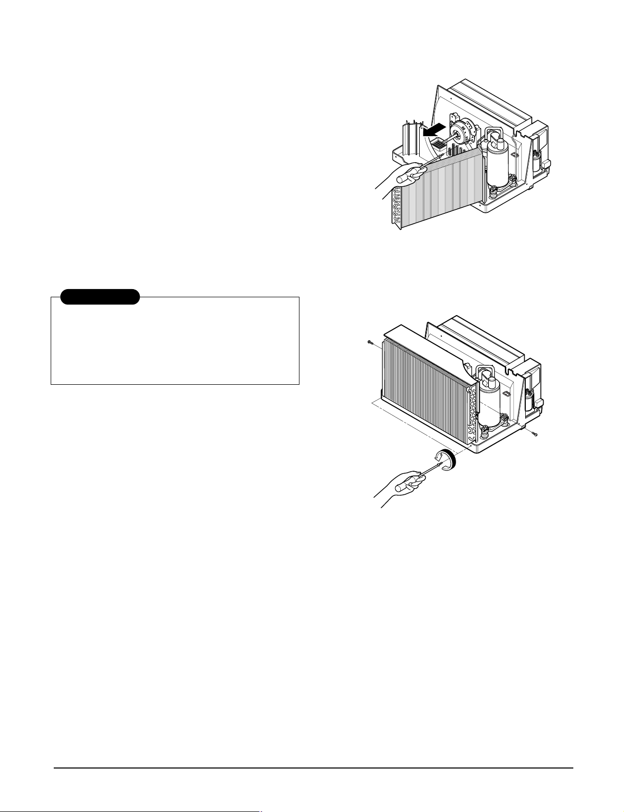
2.3.5 OUTDOOR MOTOR
1. Remove the front grille. (Refer to section 2.1.1)
2. Remote the top cover. (Refer to section 2.1.2)
3. Remove the cabinet. (Refer to section 2.1.3)
4. Remove the fan and shroud. (Refer to section
2.2.2)
5. Remove the 3 screws which fasten the motor from
the mount motor. (See Figure 18)
6. Open the capacitor cover(Refer to section 2.3.3)
7. Disconnect the outdoor motor housing.
8. Remove the motor.
9. Re-install the components by referring to the
removal procedure, above.
2.4 REFRIGERANT CYCLE
2.4.1 CONDENSER
CAUTION
Discharge the refrigerant system using a
FreonTMRecovery System.
If there is no valve to attach the recovery
system, install one (such as a WATCO A-1)
before venting the FreonTM. Leave the valve in
place after servicing the system.
Figure 18
Figure 19
1. Remove the front grille.(Refer to Section 2.1.1)
2. Remove the top cover. (Refer to Section 2.1.2)
3. Remove the cabinet. (Refer to Section 2.1.3)
4. Remove the shroud. (Refer to Section 2.2.2)
5. Discharge the refrigerant by using a refrigerant
recovery system.
6. After discharging the refrigerant completely,
unbraze the interconnecting tube at the
condenser connections.
7. Remove the condenser.
8. Re-install by referring to the procedures above.
2.4.2 EVAPORATOR
1. Remove the front grille.(Refer to Section 2.1.1)
2. Remove the top cover.(Refer to Section 2.1.2)
3. Remove the cabinet.(Refer to Section 2.1.3)
4. Remove the control box.(Refer to Section 2.1.4)
5. Discharge the refrigerant by using a refrigerant
recovery system.
6. After discharging the refrigerant completely,
unbraze the interconnecting tube at the condenser
connections.
7. Remove the evaporator.
8. Re-install by referring to the procedures above.
2.4.3 CAPILLARY TUBE
1. Remove the front grille.(Refer to Section 2.1.1)
2. Remove the top cover.(Refer to Section 2.1.2)
3. Remove the cabinet.(Refer to Section 2.1.3)
4. Remove the control box.(Refer to Section 2.1.4)
5. Discharge the refrigerant by using a refrigerant
recovery system.
6. After discharging the refrigerant completely,
unbraze the interconnecting tube of the capillary
tube.
7. Remove the capillary tube.
8. Re-install by referring to the procedures above.
Copyright ©2008 LG Electronics. Inc. All right reserved.
Only for training and service purposes
- 9 -
LGE Internal Use Only
Page 10
NOTES
— Replacement of the refrigerant.
1. When replacing the refrigerant, be sure to
discharge the refrigerant system using a Freon
recovery System.
If there is no valve to attach the recovery system,
install one (such as a WATCO A-1) before venting
the FreonTM. Leave the valve in place after
servicing the system.
2. After discharging the unit completely, remove the
desired component, and unbraze the pinch-off
tubes.
3. Braze service valves into the pinch-off tube ports,
leaving the valves open.
4. Braze the pinch-off tubes with Service valves.
5. Evacuate as follows.
1) Connect the vacuum pump, as illustrated figure
20A.
2) Start the vacuum pump, slowly open manifold
valves A and B with two full turns
counterclockwise and leave the valves open.
The vacuum pump is now pulling through valves
A and B up to valve C by means of the manifold
and entire system.
CAUTION
If high vacuum equipment is used, just crack
valves A and B for a few minutes, then open
slowly with the two full turns counterclockwise.
This will keep oil from foaming and being
drawn into the vacuum pump.
3) Operate the vacuum pump for 20 to 30 minutes,
until 600 microns of vacuum is obtained. Close
valves A and B, and observe vacuum gauge for
a few minutes. A rise in pressure would
indicate a possible leak or moisture remaining in
the system. With valves A and B closed, stop
the vacuum pump.
4) Remove the hose from the vacuum pump and
place it on the charging cylinder. See figure
20B.
Open valve C.
Discharge the line at the manifold connection.
5) The system is now ready for final charging.
TM
6. Recharge as follows :
1) Refrigeration cycle systems are charged from
the High-side. If the total charge cannot be put
in the High-side, the balance will be put in the
suction line through the access valve which you
installed as the system was opened.
2) Connect the charging cylinder as shown in figure
20B.
With valve C open, discharge the hose at the
manifold connection.
3) Open valve A and allow the proper charge to
enter the system. Valve B is still closed.
4) If more charge is required, the high-side will not
take it. Close valve A.
5) With the unit running, open valve B and add the
balance of the charge.
a. Do not add the liquid refrigerant to the Low-
side.
b. Watch the Low-side gauge; allow pressure to
rise to 30 lbs.
c. Turn off valve B and allow pressure to drop.
d. Repeat steps b. and c. until the balance of the
charge is in the system.
6) When satisfied the unit is operating correctly,
use the pinch-off tool with the unit still running
and clamp on to the pinch-off tube. Using a tube
cutter, cut the pinch-off tube about 2 inches from
the pinch-off tool. Use sil-fos solder and solder
pinch-off tube closed. Turn off the unit, allow it to
set for a while, and then test the leakage of the
pinch-off connection.
Copyright ©2008 LG Electronics. Inc. All right reserved.
Only for training and service purposes
- 10 -
LGE Internal Use Only
Page 11

Equipment needed: Vacuum pump, Charging cylinder, Manifold gauge, Brazing equipment. Pin-off tool capable
A
COMPOUND GAUGE
EVAPORATOR
(LOW PRESSURE SIDE)
COMPRESSOR
CAPILLARY TUBE
CONDENSER
(HIGH PRESSURE SIDE)
SEE INSETS
BELOW
MANIFOLD
GAUGE
B
A
B
EXTERNAL
VACUUM PUMP
A
CHARGING
CYLINDER
LOW
HI
B
C
of making a vapor-proof seal, Leak detector, Tubing cutter, Hand Tools to remove components, Service valve.
Figure 20A-Pulling Vacuum
Copyright ©2008 LG Electronics. Inc. All right reserved.
Only for training and service purposes
- 11 -
Figure 20B-Charging
LGE Internal Use Only
Page 12

3. INSTALLATION
About 1/4"
30"~60"
Awning
Cooled air
Fence
Over 20"
Heat
radiation
26"(660mm) to
39
3
/8"(1000mm)
12"(305mm) min.
Inner sill
Offset
Window
Sill
Exterior
Interior wall
Sash
3.1 HOW TO INSTALL THE UNIT
1. To prevent vibration and noise, make sure the
unit is installed securely and firmly.
2. Install the unit where the sunlight does not shine
directly on the unit.
3. The outside of the cabinet must extend outward
and there should be no obstacles, such as a
fence or wall, within 20" from the back of the
cabinet because it will prevent heat radiation of
the condenser.
Restriction of outside air will greatly reduce the
cooling efficiency of the air conditioner.
CAUTION: All side louvers of the cabinet must
remain exposed to the outside of the structure.
4. Install the unit a little slanted so the back is
slightly lower than the front (about 1/4").
This will force condensed water to flow to the
outside.
5. Install the unit with the bottom about 30"~60"
above the floor level.
Figure 21
3.2 CHECK OF INSTALLATION
The setting conditions must be checked prior to
initial starting.
The undermentioned items are especially important
checking points when the installation is finished.
1. Grounding wire (Green or Green and Yellow) is
provided in the power cord. The green wire must
be grounded.
2. Connect to a single-outlet 15A circuit.
(or 21A circuit for Electric Heater Model)
3. To avoid vibration or noise, make sure the air
conditioner is installed securely.
4 Avoid placing furniture or draperies in front of the
air inlet and outlet.
3.3 WINDOW REQUIREMENTS
NOTE: All supporting parts should be secured to
firm wood, masonry, or metal.
1. This unit is designed for installation in standard
double hung windows with actual opening widths
from 26" to 39 3/8".
2. The top and bottom window sash must open
sufficiently to allow a clear vertical opening of
12" from the bottom.
Copyright ©2008 LG Electronics. Inc. All right reserved.
Only for training and service purposes
- 12 -
Figure 22
LGE Internal Use Only
Page 13

3.4 INSTALLATION KITS CONTENTS
A
B
F
E
C
D
G
H
CENTER LINE
INNER SILL
INDOOR
FOAM STRIP
(ITEM G)
ITEM NAME OF PARTS Q'TY
A SUPPORT, BRACKET 1
B LEVELING BOLT 1
C LEVELING BOLT 1
D SCREW: 5/8" 2
E SCREW: 5/8" 5
F FOAM SEAL 1
G FOAM STRIP 1
H L BRACKET 1
3.5 SUGGESTED TOOL REQUIREMENTS
SCREWDRIVER(Phillips and Flathead), RULER, KNIFE, HAMMER, PENCIL, LEVEL
3.6 HOW TO INSTALL
CAUTION
To avoid the possibility of personal injury, unplug
power to unit before installing or servicing.
Carefully remove air conditioner from carton, check for
possible shipping damage. Pick a location which will
allow you to blow the cold air into the area you want.
Windows used for installation must be strong enough to
support the weight of the air conditioner. Good
installation with special attention to the proper position
of the unit will lessen the chance that service will be
needed.
When cooling more than one room, installation location
is very important. To cool your rooms, cold air must be
blown from the air conditioner in a straight path.
If air conditioner is blocked by a storm window frame,
see Step 7 and 8 on Page 14 before beginning to
install.
1. Cut the FOAM STRIP (ITEM G) to fit the
underside of the window sash. Open the window,
peel off the backing and attach the FOAM STRIP
as shown in Figure 23.
Figure 23
Figure 24
2. Mark center line with pencil on the center of the
Copyright ©2008 LG Electronics. Inc. All right reserved.
Only for training and service purposes
inner sill, as shown in Figure 24.
- 13 -
LGE Internal Use Only
Page 14

3. Install support bracket on window. See Figure 25.
SCREW
(ITEM D)
SCREW
(ITEM D)
LEVELING BOLT
(ITEM B or C)
LEVELING BOLT
(ITEM B or C)
ADJUSTMENT SLOT
CENTER LINE
OF WINDOW
CENTER LINE
OF WINDOW
OUTDOORINDOOR
INNER SILL
SCREW
LEVELING
BOLT
OUTER SILL
SUPPORT
BRACKET
ABOUT 1/4"
OUTDOORINDOOR
LEVELING BOLT
SUPPORT
BRACKET
STOPPER
SUPPORT
BRACKET
POCKET
HAND GRIP
WINDOW SASH
INDOOR
SECTION
INNER SILL
OUTER SILL
OUTDOOR
SECTION
TOP CHANNEL
CURTAIN
Failure to securely install support bracket may result
in unit falling from window if window sash is raised
after unit is installed. This could result in personal
injury.
Install leveling bolt up through bottom side of
support bracket. You can choose a short bolt
(ITEM C) or a long one (ITEM B) according to
window type. Also, you should select the position
of hole on bracket.
Position bracket on sill 1 inch (25.4mm) to left of
center line of window (See Figure 25).
Fasten bracket loosely to sill with screws (ITEM D)
provided.
Adjust leveling bolt so that the air conditioner will
be installed with a very slight tilt (about 1/4")
downward toward the outside for proper drainage.
Tighten bracket screws.
CAUTION
Figure 25
Figure 26
INNER
WINDOW
SILL
1"(25.4mm)
OUTER
WINDOW
SILL
CLOSE-UP VIEW
CLOSE-UP VIEW
OF SUPPORT BRACKET
OF SUPPORT BRACKET
(ITEM A)
(ITEM A)
4. INSTALL THE AIR CONDITIONER IN THE
WINDOW
• Carefully lift the air conditioner and slide it into the
open window. Be careful not to hurt waist in this
operation.
• Use the two hand grips on top sides of unit to lift
unit.
• Make sure that support bracket is inserted in the
pocket under base fan, and that curtain frame guide
is stopped by stopper on the support bracket as
shown in Figure 28.
NOTE: When unit is properly centered and pushed
outward to correct bracket location, you will feel unit
drop securely in place on the support bracket. Hold
unit firmly during this procedure.
• Lower top window sash all the way down so that
sash sits firmly in top channel of unit and
expandable curtain frames.
CAUTION
During the following step, hold unit firmly until
window sash is lowered to top channel behind
curtain frames. Personal injury or property damage
may result if unit falls from window.
Figure 27
Figure 28
CENTER LINE
Copyright ©2008 LG Electronics. Inc. All right reserved.
Only for training and service purposes
- 14 -
LGE Internal Use Only
Page 15

5. SECURE THE CURTAIN FRAMES
ITEM E
L BRACKETL BRACKET
FOAM SEAL
(ITEM F)
FOAM SEAL
(ITEM F)
INNER
SILL
WOOD STRIP MOUNTED
ON TOP OF INNER SILL
3/4"(19mm)
CLEARANCE
1 1/2" min.
(38mm)
STORM
WINDOW
FRAME
OUTDOORINDOOR
When storm window
frame is located on outer sill
OUTER
SILL
WOOD STRIP
FOR SUPPORT
BRACKET
WOOD STRIP
FOR SUPPORT
BRACKET
(a) When window frame is located on inner sill.
WINDOW FRAME
WINDOW FRAME
• Install a wood strip (window width long and
window frame height high) on the inner sill.
WOOD STRIP
INNER
SILL
OUTER
SILL
OUTER
SILL
SASH WINDOW
19/32"(15mm)
(b) When the window frame is higher than
19/32"(15mm)
• Install a wood strip (about 4"(102mm) long) on
the outdoor sill to raise support bracket.
WOOD STRIP
INNER
SILL
Expand the curtain frames and secure them using 5
screws (ITEM E) as shown in Figure 29.
When curtain frame opens or closes, you may feel a
slight resistance. This is normal.
6. FOAM SEAL AND WINDOW LOCK
• Cut the foam seal (ITEM F) to the window width.
Stuff the foam seal between the glass and the
window to prevent air and insects from getting into
the room, as shown in Figure 29.
• Install the L bracket to prevent window from being
raised which may result in unit falling.
Figure 29
CAUTION
Failure to securely install support bracket may
result in unit falling from window if window sash is
raised after unit is installed. This could result in
personal injury.
NOTE: If window sash has a metal surface. use
sheet metal screws instead of the provided wood
screws. Obtain sheet metal screws at local hardware
store.
7. IF AIR CONDITIONER IS BLOCKED BY STORM
WINDOW FRAME
• If storm window presents interference, fasten a
2"(51mm) wide wood strip to the inner window sill
across the full width of the sill. The wood strip
should be thick enough to raise the height of the
window sill so that unit can be installed without
interference from the the storm window frame. See
Figure 30.
Top of wood strip should be approximately
3/4"(19mm) higher than the storm window frame to
help condensation to drain properly to the outside.
• Install a second wood strip (approximately
6"(152mm) long by 11/2"(38mm) wide and same
thickness as first strip) in the center of the outer sill
flush against the back of the inner sill. (Figure 30)
8. INSTALLATION FOR OTHER TYPE WINDOWS.
• Dimensions and geometry of windows are different
depending on their manufacturing. Check your
window and refer to FIG.31 to install the support
bracket firmly.
Copyright ©2008 LG Electronics. Inc. All right reserved.
Only for training and service purposes
- 15 -
Figure 30
Figure 31
LGE Internal Use Only
Page 16

2
2
F
C
3
G
A
B
RIGHT SIDE
HORIZONTAL
LINE
D
305(12")
600(23 5/8")
458(18
1
/32")
172(6
25
/32") 60(2 3/8")
255(10")
3.7 REMOVAL FROM WINDOW
• Turn off and unplug the air conditioner.
• Unscrew the side screws that you installed in Step
5. 6.
• Close the curtain frame and remove foam seal and
L bracket from the windows.
• Keep a firm grip on the air conditioner raise the
sash.
• Lift the air conditioner from the window and
remove the foam strip from between the windows.
NOTE: When cooling season is over, unit is
removed from window for cleaning and storage.
There may still be some condensation water in the
basepan. Remove the unit carefully to avoid water
being spilled out on floor. Always store unit flat on its
base. Do not stand on end. Be sure to remove
support bracket, L bracket, and foam seal from
window and save. Window will not close if support
bracket remains installed.
• Remove the support bracket from window frame.
4. TROUBLESHOOTING GUIDE
4.1 OUTSIDE DIMENSIONS
Figure 32
Copyright ©2008 LG Electronics. Inc. All right reserved.
Only for training and service purposes
- 16 -
Figure 33
LGE Internal Use Only
Page 17

CAPILLARY TUBE
COMPRESSOR
INDOOR MOTOR
EVAPORATOR COIL
CONDENSER COIL
CROSS FLOW FAN
FAN
OUT MOTOR
4.2 PIPING SYSTEM
(LIQUID REFRIGERANT)
CAPILLARY TUBE
OUTSIDE COOLING
AIR FOR REFRIGERANT
PASS THROUGH
SUCTION LINE
COOL LOW PRESSURE VAPOR
COOLED
AIR
COMPLETE LIQUID
BOIL OFF POINT
LIQUID
PRESSURE
DROP
ROOM AIR HEAT LOAD
VAPOR INLET
HOT
DISCHARGED
AIR
LIQUID OUTLET
HIGH PRESSURE VAPOR
LIQUID REFRIGERANT
LOW PRESSURE VAPOR
ROOM AIR CONITIONER
EVAPORATOR COILS CONDENSER COILS
CYCLE OF REFRIGERATION
MOTOR
COMPRESSOR
OIL
Figure 34
Following is a brief description of the important components and their functions in the refrigeration system.
Refer to Figure 35 to follow the refrigeration cycle and the flow of the refrigerant in the cooling cycle.
Copyright ©2008 LG Electronics. Inc. All right reserved.
Only for training and service purposes
Figure 35
- 17 -
LGE Internal Use Only
Page 18

4.3 TROUBLESHOOTING GUIDE
Ineffective Cooling
Check outdoor coil
(heat exchanger) & the fan
operation.
Check gas leakage.
Repair gas leak.
Replace the unit if it
is beyond repair.
Satisfactory operation with
temperature difference of
inlet & outlet air ;
44~50°F(7~10°C)
Check heat load
increase.
Clean condenser.
Not on separate circuit.
Check inside gas
pressure.
Adjust refrigerant charge.
Malfunction of compressor.
Replace compressor.
Check cold air circulation
for smooth flow.
Dirty indoor coil
(Heat exchanger)
Correct above trouble
Check clogging in refrigeration circuit.
Repair clogging in refrigeration circuit.
Obstruction at air outlet
Clogged air filter.
Malfunction of fan
In general, possible trouble is classified within one of two possible categories.
The first is designated Starting Failure and is caused from an electrical defect, while the other is ineffective Air
Conditioning caused by a defect in the refrigeration circuit or improper application.
Unit runs but cools poorly.
Copyright ©2008 LG Electronics. Inc. All right reserved.
Only for training and service purposes
- 18 -
LGE Internal Use Only
Page 19

Fails to Start
Check circuit breaker
and fuse.
Check of control switch.
Only the fan fails to start.
Improper wiring.
Defect of fan motor
capacitor.
Irregular motor resistance
(
).
Irregular motor insulation
(
).
Replace fan motor.
Regular but fails to start.
Replace compressor
(locking of rotor, metal).
Improper thermistor setting.
Loose terminal connection.
Improper wiring.
Irregular motor resistance ( )
Irregular motor insulation ( )
Replace compressor
(Motor damaged)
Drop of power voltage.
Capacitor check.
Replacement
Only the compressor fails to
start.
Defect of compressor
capacitor.
Check power source.
Check control switch
setting.
Copyright ©2008 LG Electronics. Inc. All right reserved.
Only for training and service purposes
- 19 -
LGE Internal Use Only
Page 20

• Check the Fuse.
• Check the wiring diagram.
Is the Trans input power
AC 115V?
Is the Trans output power
about AC 14V?
Is the Trans. output shorted?
Is output Voltage of IC02D
DC 5V?
Is the voltage No.18 of Micom
DC 5V?
Exchange AC PCB Ass'y.
Is the
connection between
AC and DC
all right?
Is the reset circuit all right?
(The No.14 of
Micom is 5V.)
• Check the Fuse.
• Check the wiring diagram.
• Check the Main
PCB pattern.
• Exchange the Trans.
• Exchange IC02D.
• Exchange IC01A, C02A.
• Connect connector
exactly.
• Check the PCB
pattern.
NO
NO
NO
NO
NO
NO
YES
YES
YES
YES
YES
YES
NO
YES
■ ELECTRICAL PARTS TROUBLESHOOTING GUIDE: LP6000ER/LP7000R
Possible Trouble 1 The unit does not operate.
Copyright ©2008 LG Electronics. Inc. All right reserved.
Only for training and service purposes
- 20 -
LGE Internal Use Only
Page 21

Possible Trouble 2 The compressor does not operate.
Is setting
Temp. set lower than Room
Temp.-1°F?
Is the voltage No.10
of IC01M 0V?
• Exchange IC01M.
• Select the setting Temp. to lower Number.
• Wait 3 Minutes.
Does the
compressor activate
after 3 minutes?
• Exchange MAIN
PCB Ass'y.
Is the voltage N0.9 of
IC01M DC 12V?
• Check the RY-COMP.
• Check the wiring
Diagram.
NO
NO
NO
YES
YES
YES
YES
Is the wire connection of
RY-COMP all right?
• Check the RY-COMP.
• Connect LEAD Wire to
RY-COMP again.
NO
YES
NO
Possible Trouble 3 The compressor always operate.
Copyright ©2008 LG Electronics. Inc. All right reserved.
Only for training and service purposes
- 21 -
LGE Internal Use Only
Page 22

Possible Trouble 4 FAN does not operate.
• Exchange IC01M.
• Exchange IC01M.
Is the voltage NO.1 or 2 or 4
of IC01M DC 12V?
Is the voltage NO.16 or 15 or 13
of IC01M 0V?
• Check the RY-Hi or
RY-Med or RY-Lo.
•
Check the wiring diagram.
NO
NO
YES
YES
NO
NO
YES
YES
Has the mode
key been pushed once more
after cool mode?
Is the voltage No.3 of
CN-AC/DC of AC PCB
Ass'y DC 5V?
• Reference to
OWNER'S MANUAL.
• Set the mode key to
Energy Saver mode.
• Check the Energy
Saver mode key.
• Check the pattern of
AC & DC PCB.
Possible Trouble 5
The function of Energy Saver does not operate.
Copyright ©2008 LG Electronics. Inc. All right reserved.
Only for training and service purposes
- 22 -
LGE Internal Use Only
Page 23

Possible Trouble 6 Remote controller does not operate.
NO
NO
NO
NO
YES
YES
YES
Is the IC01G all right?
Is the connection of
CN-AC/DC
all right?
• Exchange the DC
PCB Ass'y.
• Exchange IC01G.
• Exchange IC03G
(Q01G, Q02G, Q03G
for Deluxe Model).
• Connect connector
to
CN-AC/DC
exactly.
Does the IC03G
(Q01G, Q02G, Q03G for Deluxe Model)
operate normally on DC
PCB Ass'y?
• Check the PCB pattern.
Is the voltage of Battery
about over 2.3V?
• Exchange Receiver Ass'y.
Is the connection of
CN-AC/DC
all right?
Is the voltage No.10
of CN-AC/DC on DC PCB
Ass'y DC 5V?
• Exchange the battery.
• Check the PCB pattern.
• Connect connector to
CN-AC/DC
completely.
NO
NO
NO
YES
YES
YES
Possible Trouble 7 It displays abnormally on DC PCB Ass’y.
Copyright ©2008 LG Electronics. Inc. All right reserved.
Only for training and service purposes
- 23 -
LGE Internal Use Only
Page 24

Possible Trouble 8 It displays abnormally on DC PCB Ass’y.
NO
NO
NO
NO
YES
YES
YES
Are the IC01G and IC02G
all right?
Is the connection of
CN-AC/DC all right?
• Exchange the DC
PCB Ass'y.
• Exchange IC01G,
IC02G.
• Exchange IC03G.
• Connect connector
to CN-AC/DC exactly.
Does the IC03G
operate normally on AC
PCB Ass'y?
Copyright ©2008 LG Electronics. Inc. All right reserved.
Only for training and service purposes
- 24 -
LGE Internal Use Only
Page 25

ROOM AIR CONDITIONER VOLTAGE LIMITS
NAME PLATE RATING MINIMUM MAXIMUM
115V ±10% 103.5V 126.5V
COMPLAINT CAUSE REMEDY
Fan motor will not run.
Fan motor runs
intermittently
Fan motor noise.
Compressor will not run,
but fan motor runs.
No power
Power supply cord
Wire disconnected or
connection loose
Capacitor (Discharge
capacitor before testing.)
Will not rotate
Revolves on overload.
Fan
Cross flow fan
Loose clamper
Worn bearings
Voltage
Wiring
Check voltage at outlet. Correct if voltage is missing.
Check voltage to connector of CN-PWR and 3 port of
comp-relay. If none, check power supply cord.
Replace cord if circuit is open.
Connect wire. Refer to wiring diagram for terminal
identification. Repair or replace loose terminal.
Test capacitor.
Replace if not within ±10% of manufacturer's rating.
Replace if shorted, open, or damaged.
Fan blade hitting shroud or blower wheel hitting
scroll. Realign assembly.
Units using slinger ring for condenser fan must have
1
/4to 5/16inch clearance to the base. If it hits the
base, shim up the bottom of the fan motor with
mounting screw(s).
Check fan motor bearings; if motor shaft will not
rotate, replace the motor.
Check voltage. If not within limits, call an electrician.
Test capacitor.
Check bearings. Does the fan blade rotate freely?
If not, replace fan motor.
Pay attention to any change from high speed to
low speed. If the speed does not change, replace the
motor.
If cracked, out of balance, or partially missing,
replace it.
If cracked, out of balance, or partially missing,
replace it.
Tighten it.
If knocking sounds continue when running or loose,
replace the motor. If the motor hums or noise
appears to be internal while running, replace motor.
Check voltage.
If not within limits, call an electrician.
Check the wire connections, if loose, repair or
replace the terminal. If wires are off, refer to wiring
diagram for identification, and replace. Check wire
locations. If not per wiring diagram, correct.
Copyright ©2008 LG Electronics. Inc. All right reserved.
Only for training and service purposes
- 25 -
LGE Internal Use Only
Page 26

COMPLAINT CAUSE REMEDY
Compressor will not run,
but fan motor runs.
Compressor cycles on
overload.
Compressor cycles on
overload.
Thermistor
Capacitor (Discharge
capacitor before servicing.)
Compressor
Overload
Voltage
Overload
Fan motor
Condenser air flow
restriction
Check the status the setting temperature if not lower
than room temperature, please decrease the setting
temperature.
Check continuity of the thermostat. Replace
thermostat if circuit is open.
Check the capacitor.
Replace if not within ±10% of manufacturers rating.
Replace if shorted, open, or damaged.
Check for compressor for open circuit or ground. If
open or grounded, replace the compressor.
Check the compressor overload, if externally
mounted. Replace if open. (If the compressor
temperature is high, remove the overload, cool it,
and retest.)
Check the voltage.
If not within limits, call an electrician.
Check overload, if externally mounted.
Replace if open. (If the compressor temperature is
high, remove the overload, cool, and retest.)
If not running, determine the cause. Replace if
required.
Remove the cabinet. inspect the interior surface of
the condenser; if restricted, clean carefully with a
vacuum cleaner (do not damage fins) or brush.
Clean the interior base before reassembling.
Compressor cycles on
overload.
Insufficient cooling or
heating
Excessive noise
Condenser fins (damaged)
Capacitor
Wiring
Refrigerating system
Air filter
Exhaust damper door
Unit undersized
Cross flow fan or fan
Copper tubing
If condenser fins are closed over a large area on the
coil surface, head pressures will increase, causing
the compressor to overload. Straighten the fins or
replace the coil.
Test capacitor.
Check the terminals. If loose, repair or replace.
Check the system for a restriction.
If restricted, clean or replace.
Close if open.
Determine if the unit is properly sized for the area to
be cooled.
Check the set screw or clamp. If loose or missing,
correct. If the blower or fan is hitting air guide,
rearrange the air handling parts.
Remove the cabinet carefully and rearrange tubing
not to contact cabinet, compressor, shroud, and
barrier.
Copyright ©2008 LG Electronics. Inc. All right reserved.
Only for training and service purposes
- 26 -
LGE Internal Use Only
Page 27

5. SCHEMATIC DIAGRAM
OR
BR YL
OUTDOOR
FAN
MOTOR
1
6
8
7
5
3
2
4
5.1 CIRCUIT DIAGRAM
■
MODEL : LP6000ER/LP7000R
LOCATION
NO.
1
INDOOR MOTOR ASSY
2
OUTDOOR MOTOR ASSY
3
CAPACITOR
4
COMPRESSOR
5
OVERLOAD PROTECTOR
6
DC PCB ASSEMBLY
7
AC PCB ASSEMBLY
8
THERMISTOR
Copyright ©2008 LG Electronics. Inc. All right reserved.
Only for training and service purposes
DESCRIPTION
PART NO.
LP6000ER LP7000R
4681A20088A
4681A20089A
6120AR2359V 0CZZA20001W
2520UABC2JA 2520UAEC2CB
6750U3L001A 6750U-L060A
6871A20342A
6871A20343A
6323A20004E
- 27 -
S: Service Parts
N: Non Service Parts
Q'TY
PER SET
1
1
1
1
1
1
1
1
LGE Internal Use Only
RE-
MARKS
S
S
S
S
S
S
S
S
Page 28

5.2 ELECTRONIC CONTROL DEVICE
O
7805
I
12V
+
5V
5V
F
C
CAPACITOR
C05D
STO2D-200
HIGH VOLTAGE GND(DC)
EN
BP
MAIN
POWER
MOTOR
FAN
OUTDOOR
TVR 14561
COMP
1
1
3
FUSE
250V/T2A
4
CN-OUT
RY-COMP
G4A-1A-E-LG
(14271)
HERM
11
FAN
C
CAPACITOR
33
CN-PWR
YW396-03AV
ZNR01J
40mH/1A
NF01J
275V
100nM
100nM
275V
4.7uF
450V
C01D
R03D
1/4W
300K
SCK102
5D2
S
266P
IC01D
TNY
SD01D
CN-AC/DC
D01D~D04D
C01J
C02J
1
NTC
SPARE
CN-AC/DC
1
INDOOR
MOTOR
FAN
1
1
2
2
7
9
7
9
135
135
1
1
RY-HI
RY-MED
RY-LOW
CN-MOTOR
YW396-09AV
3
3
2
2
3
3
SW1
PIPE-TH
1
1
3
3
2
2
SMW200-03(YL)
SMW200-03(WH)
CN-HVB
CN-12V
99
12
10
11
4
3
2
5V
12V
RY-MED
RY-HI
2
12V
3
4
121011
7
8
RY-COMP
RY-LOW
12V
OP1
8
7
ROOM-TH
3
3
2
2
1
1
SMW200-03(RD)
CN-TH2
SMW200-03(BL)
CN-TH1
5
66
5
5V
-4002
C08D
220
10V
ZBF503D
UG2D
S/TRANS
R01D
1/8W
ZD01D
472nM
400V
C05D
470/35V
TLP181BL
IC03D
C04D
1
4
104/50V
C02D
3.6mH(2.0mH)
4
3
1
2
11V
39
50V
103
C07D
R02D
1/8W
20K
C06D
25V
330
681/50V
C03D
D02D
L1
IC02D
103
C09D
50V
Q01T
2SC5343
R03T
12K
R02T
1K
R01T
4.7K
50V
0.01
C01T
143
5V
ULN2004A
IC01G
7
845
6
150
R07G
5V
10
9
R06G
R05G
R04G
13
11
12
150
150
150
1
2
R03G
R02G
R01G
16
15
150
150
150
C02F
0.001
R03F
10K
f
b
f
b
c
AIR PURIFIER
E/SAVER
FAN
TIMER
DRY
88 SEGMENT
c
1
d
g
8
4
7
6
e
g
dfe
d
g
e
c
COOL
PURIFIER
D03G
SW03G
AIR
TIMER
SW02G
D02G
10
Digit1
9
3
a
b
a
5
Digit0
a
FAN
D01G
SW01G
MICOM
Osc out
TMP87CH47U
VDD
RECEIVER
14
3
C06D
50V
+
10V
220
0.01
5V
Vout
BZ01E
PKM13EPY
C02L
10V
220
R02E
20
GND
12V
+
5V
IC01M
Vcc
ULN2004A
9
16
15
128
OR1H
1%
R21H
5V
12.1K
OR2H
131211
456107
1%
R22H
12.1K
HVB
Receiver
LED out3
Buzzer
R01E
1K
C01L
680pF
50V
R01L
1K
35
LED out1
LED out2
34
LED out0
3736
KEY1
FILTER
38
KEY0
39
313233
272829
30
ION
HI
MED
R01P
5V
20K
VAref
Pipe TH
Option1
Option2
Room TH
21
242526
SYNC
4WAY
LOW
23
COMP
22 1920 18
VSS
17
5V
12.1K
6.2K
1%
1%
R04H
5V
R02H
R01B
1M
OSC01B
RT8.00MG
Digit3 (Scan3)
Digit0 (Scan0)
Digit2 (Scan2)
Digit1 (Scan1)
44
SEG-f
4240
SEG-g
41
SEG-d
SEG-e
43
SEG-c
SEG-a
SEG-b
1235674
C01F
0.001
R01F
10K
R05P
10K
Digit4 (Scan4)
Osc in
/Reset
121416 15
TEST
13
SDA
SCL
8
9
10
11
Q02G
TEMP UP
D07G
SW07G SW05G
TEMP DOWN
D05G D06GD04G
SW04G
MODE
SW06G
ON/OFF
A101S
Q01G
A101S
Q04G
A101S
Q03G
A101S
A2
GND
A1
423
SCL
SDA
WP
576
R04P
1K
50V
C01A
0.01
5V
3.6V
1uF
10V
C02A
+
2
1
3
IC01A
S7136
R01A
20K
Non Auto Restart
EEPROM
A0
24LC01BT
C01P
25V
0.01
1
Vcc
8
Model
Auto Restart
R02P
20K
R03P
20K
X
5V
O
EEPROM
OX
R04P
+
1N4007
HVB
+
+
■ MODEL: LP6000ER/LP7000R
Copyright ©2008 LG Electronics. Inc. All right reserved.
Only for training and service purposes
- 28 -
LGE Internal Use Only
Page 29

5.3 COMPONENTS LOCATION(FOR AC P.C.B ASM)
LOW
GND
GND
5V
PIPE TH
ROOM TH
COMP
12V
HI
HVB
MED
F/C
CN-12V
C05D
C03D
D07D
C04D
SMPS
CN-MOTOR
CO7D
L1
R01D
R02D
C06D
CN-TH2
CN-HVB
C08D
J01
PCB P/N0 6870A90129A
PCB ASM P/NO 6871A20343
C01D
NTC
SD01D
R03D
D04D
IC01D
D01D
D03D
D02D
C02J
RY-MED
250V/T3.15A( )
250V/T2A( )
RY-LOW
CN-PWR
IC03D
C02D
ZD01D
C01J
FUSE
ZNR01J
RY-HI
OP1
IC02D
C09D
J03
J02
J04
3
RY-COMP
4
CN-AC-DC
1
12
CN-OUT
88 SEGMENT
JP16
IC01A
CN-AC/DC
JP08
JP05
JP27
C02A
OSC01B
JP03
JP04
JP02
C05D
JP06
JP07
JP25
FAN
BZ01E
JP11
JP23
JP10
JP09
POWER
SW01G
SW06G
TEMP DOWN
D01G
JP13
D05G
JP12
JP01
SW05G
JP15
D06G
C02L
RECEIVER
AIR PURIFIER
JP22
JP21
SW04G
TEMP UP
D07G
TIMR
JP14
SW07G
MODE
SW02G
D04G
LED3
D02G
TIMER
AIR PURIFIER
COOL
JP29
JP20
JP19
FAN
LED1
D03G
LED2
SW03G
DRY
LED4
E/SAVER
JP28
LED6
:6871A20342
PCB P/No:6870A90128A
PCB ASSEMBLY P/No
LED5
■ MODEL: LP-6000ER/LP7000R
5.4 COMPONENTS LOCATION(FOR DC P.C.B ASM)
■ MODEL: LP-6000ER/LP7000R
Copyright ©2008 LG Electronics. Inc. All right reserved.
Only for training and service purposes
- 29 -
LGE Internal Use Only
Page 30

6. EXPLODED VIEW
354210
249951
352380B
549990
130910
359011
135500A
152302
135500B
268711A
237900
137215
135316
554030
559010
552111
264110
263230
268711D
135500D
W0CZZ
152303
435301
147582
135301
346810
148000
349600
352380A
35211A
352115
567502
554160
550140
130410
W4810A
721273
W4810B
135500C
352113
546810
■ Model: LP6000ER/LP7000R
Copyright ©2008 LG Electronics. Inc. All right reserved.
Only for training and service purposes
- 30 -
LGE Internal Use Only
Page 31

P/NO : 3828A20190H
February, 2008
 Loading...