

LG GCE-8080N Service Manual

3
INTRODUCTION
FEATURES
1. General
1) Enhanced IDE interface.
2) Ultra Slim Type CD-RW Drive (Height : 12.7 mm)
3) 2 Mbytes buffer memory.
4) Exact Link Function Support.
5) 3 Way eject support (Software, Open button, Emergency eject).
6) Supports Power saving mode and Sleep mode.
7) Vertical and Horizontal Operation.
2. Supported disc formats
1) Reads and writes data in each CD-ROM, CD-ROMXA, CD-Text, Video CD, and CD-EXTRA
2) Reads data in Photo CD (Single and Multi session).
3) Reads and writes standard CD-DA.
4) Reads and writes CD-R discs conforming to “Orange Book Part 2”.
5) Reads and writes CD-RW discs conforming to “Orange Book Parts 3”.
3. Supported write method
1) Disc at once, Session at once, Track at once (TAO), Variable packet, Fixed packet, and Multi-session.
4. Performance
1) Random 140 ms average access time.
2) CD-R record speed : 2x, 4x, 8x
3) CD-RW record speed : 2x, 4x, 8x
4) CD-ROM : Max 3,600 KB/sec(Max 24x) Sustained Transfer rate.
5) Supports real time error correction and real time layered error correction at each speeds.
6) Supports CD-R write operation at double speed, quadruple speed, eighth speed.
7) Supports CD-RW write operation at double speed , quadruple speed and eighth speed.
8) PIO Mode 4, Multi DMA Mode 2 Support.
9) Multimedia MPC-3 Spec compliant
10) Support CD-TEXT read and Write.
11) Support Exact Link function
5. Audio
1) Outputs 16 bit digital data over ATA interface.
2) 4 Times Digital Filter for CD Audio
3) Software Volume Control
This service manual provides a variety of service
information.
It contains the mechanical structure of the CDR/RW Drive and the electronic circuits in schematic
form. This CD-R/RW Drive was manufactured and
assembled under our strict quality control standards
and meets or exceeds industry specifications and
standards.
This CD-R/RW drive is an internal slim drive unit
designed for use with IBM PC, HP Vectra, or
compatible slim notebook computer. It can write as
much as 700 Mbytes of digital data into CD-R disc,
and can read as much as 700 Mbytes of digital data
stored in a CD-ROM, CD-R and CD-RW disc.
This CD-R/RW Drive can easily meet the
upcoming MPC level 3 specification, and its
Enhanced Intelligent Device Electronics (E-IDE) and
ATAPI interface allows Plug and play integration in
the majority of today’s PCs without the need of an
additional interface card.
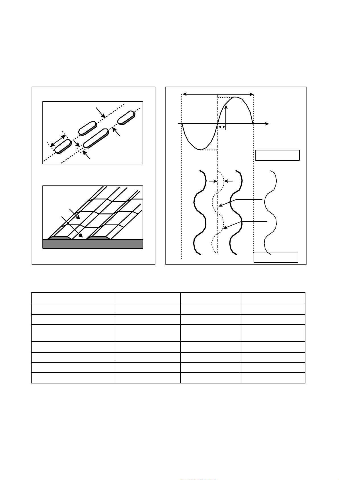
The differences of CD-R/CD-RW discs and General CD-ROM
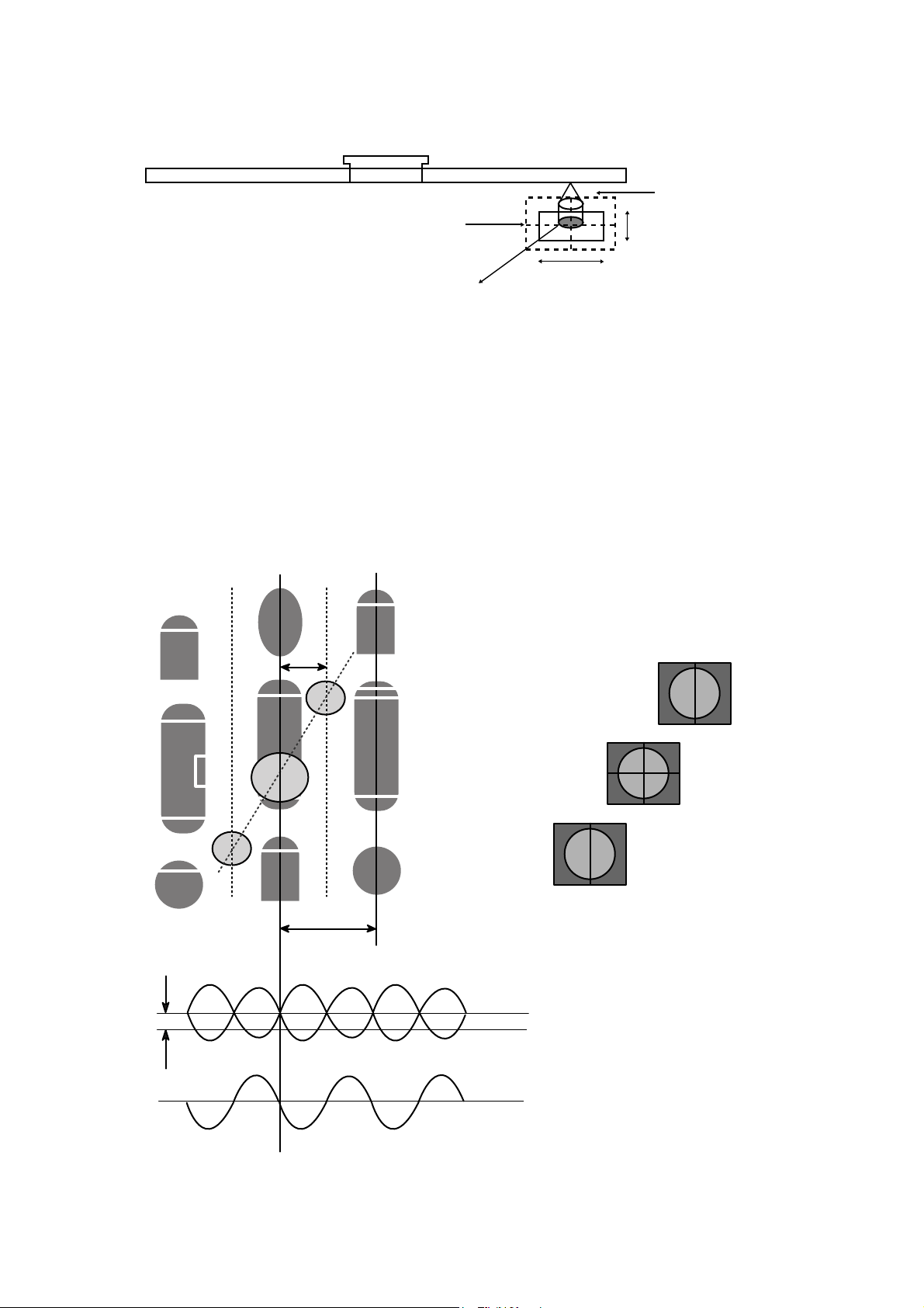
1. Recording Layer
Recordable CD has a wobbled pre-groove on the surface of disc for laser beam to follow track.
2. Disc Specification
Read-only Disc
CD-R and CD-RW Disc
3~11T
1.6um
0.4~0.5 um
(Pit)Groove
Land
Track pitch(p)
Radial Direction
Iw
A
O
a
a
Groove
Land
Radial Error Signal
The Groove wobble
Average center
Actual center
CD-ROM CD-R CD-RW
Standard Yellow Book Orange Book II Orange Book III
Record Not available Write once Re-writable
I 11/Itop
> 0.6 > 0.6 0.55 > M11> 0.70
(HF Modulation)
Write Laser Power(mW) 10-30 mW 6-25 mW
Read Laser Power(mW) < 0.5 mW < 0.7 mW < 1.0 mW
Jitter < 35 nsec < 35 nsec < 35 nsec
Reflectivity (R
top) 70 % 65 % 15 % ~ 25 %
12
CD-ROM (READ-ONLY DISC)
a=30nm
13
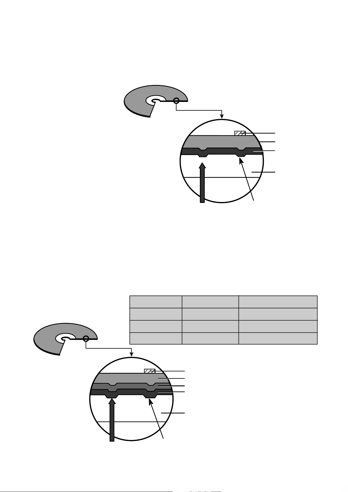
3. Disc Materials
1) CD-ROM disc
Laser Beam
Groove
Substrate
(Polycarbonate)
Organic Dye Layer
Reflective Layer
Protective Layer
Label Printing
2) CD-R disc
Pigment Reflective Layer Color
Phtalocyanine Gold/Silver Yellow/White
Cyanine Gold/Silver Dark Green/Bright Green
Azo Gold/Silver Dark Blue
• It is composed of Silver _ colored aluminum plate and Reflective layer.
• Groove (Pit) of aluminum plate make a track.
• Laser wavelength : 780 nm, Laser Power (Read): 0.5mW
• Signal is detected by the
difference of reflective beam
intensity between “pit” and
“Land” on the disc.
• It is so-called WORM (Write Once Read Many) CD.
• It is composed of polycarbonate layer, Organic dye layer, Reflective layer, and Protective
layer.Gold/Silver Reflective layer is used to enhance the reflectivity
• According to the kinds of Organic dye layer, it is divided by Green CD, Gold CD, Blue CD.
• Laser Wavelength : 780 nm, Laser Power (read) : 0.7 mW
• Recording Power : 4x(10~15mW), 8x(14~20mW), 12x(15~30mW).
• When some part of dye layer is exposed to laser heat, it’s color changs black.Therefore, writing and
reading is enabled by the difference of reflectivity between changed part and unchanged part.
• Polycarbonate layer has Pre_Groove which make a Track.
Laser Beam
Pit
Substrate
(Polycarbonate)
Reflective Layer
Protective Layer
Label Printing
14
33)) CCDD--RRWW DDiisscc
4.
Reading process of Optical Disc
Laser Beam
Groove
Substrate
(Polycarbonate)
Reflective Layer
Dielectric Layer(TL)
Dielectric Layer(UL)
Protective Layer
Label Printing
• It is composed of polycarbonate layer, alloy(silver, arsenic) layer, aluminum reflectivity layer, protective layer.
• An crystalized alloy layer is transformed into noncrystalized by the laser heat. Therefore, writing and reading
is enabled by the difference of reflectivity.
• It is possible to overwrite about 1000 times.
• Laser Wavelength : 780 nm, Laser Power (Read) : 1.0mW
• Recording Power : Erase (4~12mW), Write (6~25mW)
• When disc rewriting, new data is overwritten previously recorded data.
• Polycarbonate layer has a Pre-Groove which make a track.
Lens
H
D
Beam
Spot
Focusing
Lens
Laser Spot
at Constant
Read Intensity
Reflected
Light
Signal
Laser Spot
Position
(Time)
Previously Recorded Marks
Groove Land Mirror
I
3
I
top
I
11
I
G
I
L
I
0
Numerical aperture: NA=nsinθ,
n: Refractive index
Focus depth : H =
λ/
NA
laser spot diameter :
D = λ/NA
2
θ
15
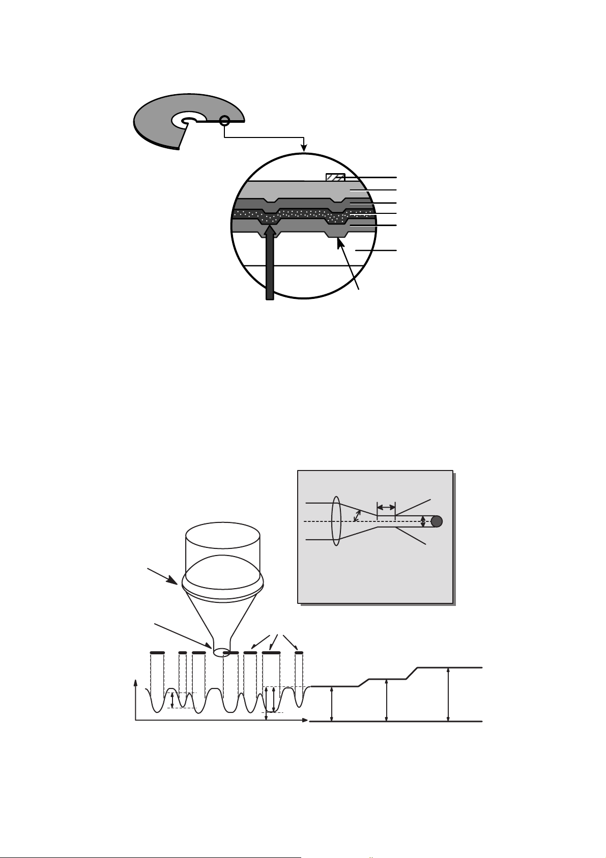
5. Writing Process of CD-R Disc
a b c d e f g
a
b
c
d
e
f
g
Incident
Laser
Powe r
(Read)
(Read)
(Write)
Laser Spot
Position
(Time)
a b c d e f g
Laser Spot
Position
(Time)
Laser
Spot
Recorded
Mark
Reflected
Light
Signal
Reflected
Light
Signal
Below "ORP"– Mark Too Short
At Optimum Record Power ("ORP")
Above "ORP" – Mark Too Long
Time
6. Writing process of CD-RW Disc
Write Power
Erase Power
Read Power
Groove
Crystal
Amorphous
Amorphous
Recorded state
(lower reflectivity)
Melting/
quenching
Heating/
gradual cooling
Crystal phase
Erased state
(higher reflectivity)
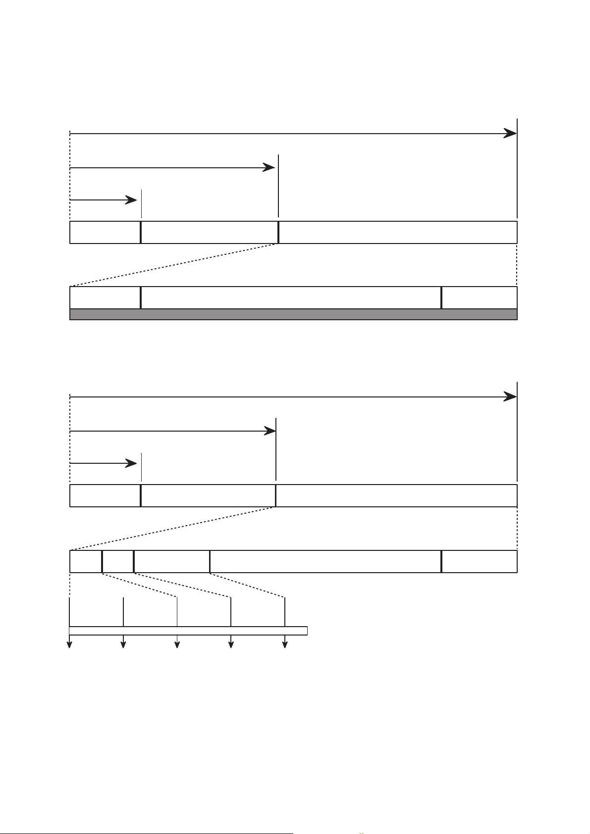
7. Organization of the PCA, PMA and Lead-in Area
1) Layout of CD-ROM disc
16
Center hole Clamping and Label Area Information Area
Lead-in Area
Lead-in Area
Diameter 15 mm
Diameter 46 mm
Diameter 120 mm
Program Area
Read Only Disc
Lead-out Area
Program Area Lead-out Area
Center hole
Clamping and Label Area
Information Area
PCA PMA
Test Area Count Area
Diameter 15 mm
Diameter 45 mm
Diameter 120 mm
Unrecorded Disc
Tsl-00:35:65 Tsl-00:15:05
Tsl-00:13:25
Tsl
99:59:74
00:00:00
in out
Test Area : for performing OPC procedures.
Count Area : to find the usable area immediately in T.A
Tsl : start time of the Lead-in Area, as encoded in ATIP
PMA : Program Memory Area
Disc Center
Disc Center
2) Layout of CD-R/RW disc
17
8. Function of PCA and PMA area
1) PCA (Power Calibration Area)
• PCA area is used to determine the correct Laser Power for a disc.
– Method 1 : PCA area is divided by a track.
– Method 2 : The previous Calibration value is referred.
– Method 3 : ROPC is used to determine Laser Power value automatically in data writing.
• CD-R Disc can write maximum 99 Tracks but CD-RW Disc can write unlimited tracks because it has a rewritable
function.
2) PMA (Program Memory Area)
• It has a track information (track No, track Start/End time) of every track before writing completed.
– PMA area has the last written point and the next writable point of a disc.
– In case of CD to CD copy, some writer may not write PMA area.
* When Disc is Finalized,
PMA information is transferred to the Lead_In area so that general Driver can read it.
* Because PCA and PMA area exist before Lead-In area, General CD Player or CD-ROM Drive can’t read
these areas.
9. OPC and ROPC
1) OPC (Optimum Power Control)
• This is the first step of writing process, because CD writer has its own laser power value and media have different
writing characteristics,
– This is determined by the Writing characteristic, speed, temperature, and humidity.
– Laser wavelength is determined by the environmental temperature (775~795nm) and Optical Laser Power is
determined by the test and retry.
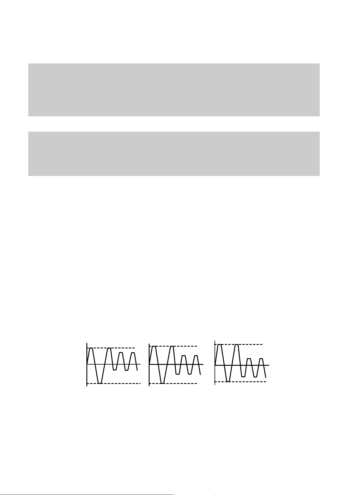
• Asymmetry and optimum writing Power
– EFM signal Asymmetry is determined by the writing power.
Therefore, Optical Power which has the same value to the preset power value can be estimated by measuring
HF signal Asymmetry on the PCA area.
• Measurement of Asymmetry
* Parameter setting (Beta) : Using AC coupled HF signal before equalization
Beta = (A1+A2)/(A1-A2)
Time
P << Po
Time
P = Po
HF Signal
A1
0
A2
Time
P >> Po
2) ROPC (Running Optimum Power Control)
• Variable primary factor of Optimum Power
– Change of Power sensitivity on the Disc. (limited to 0.05 *Po)
– Wavelength shift of the laser diode due to the operating temperature change.
– Change of the Spot aberration due to the Disc skew,
Substrate thickness, Defocus.
– Change of Disc or Optics conditions due to the long term OPC
==> It is necessary to adjust continuously to obtain the Optimum Power.
• Principle of Running OPC
– To meet the factors mentioned above,
a horizontal _ direction movement of a curve is uesd.
– Beta = f(B-level) = constant on the Recorded Disc
– Procedure of ROPC
a. Reference B-level is determined during OPC Procedure.
b. During Recording, B-level value is controlled to have a close
Reference B-level value.
c. Normalization of B-level is used to eliminate the effect of reflectivity fluctuation.
==> The reflected B-level value is normalized by the disc reflectivity itself.
18
CCDD--RR// RR WW
Media
Write Strategy
Determination
PCA Test Area
Program Area
PMA Area
Lead-In Area
Lead-out Area
OPC
PCA Count Area
ROPC
* Recording Capacity of CD-R/RW (74Minute Recording media)
• (2048 Byte/Sector) X (75 Sector/Second) X (60 Second/Minute) X 74 Minute
= 681,984,000 Bytes = 682 Mbytes
• But the actual recording capacity is about 650 Mbytes. (according to the ISO 9660 standard, approximately
30 Mbytes are used to make directory structure and volume names.)
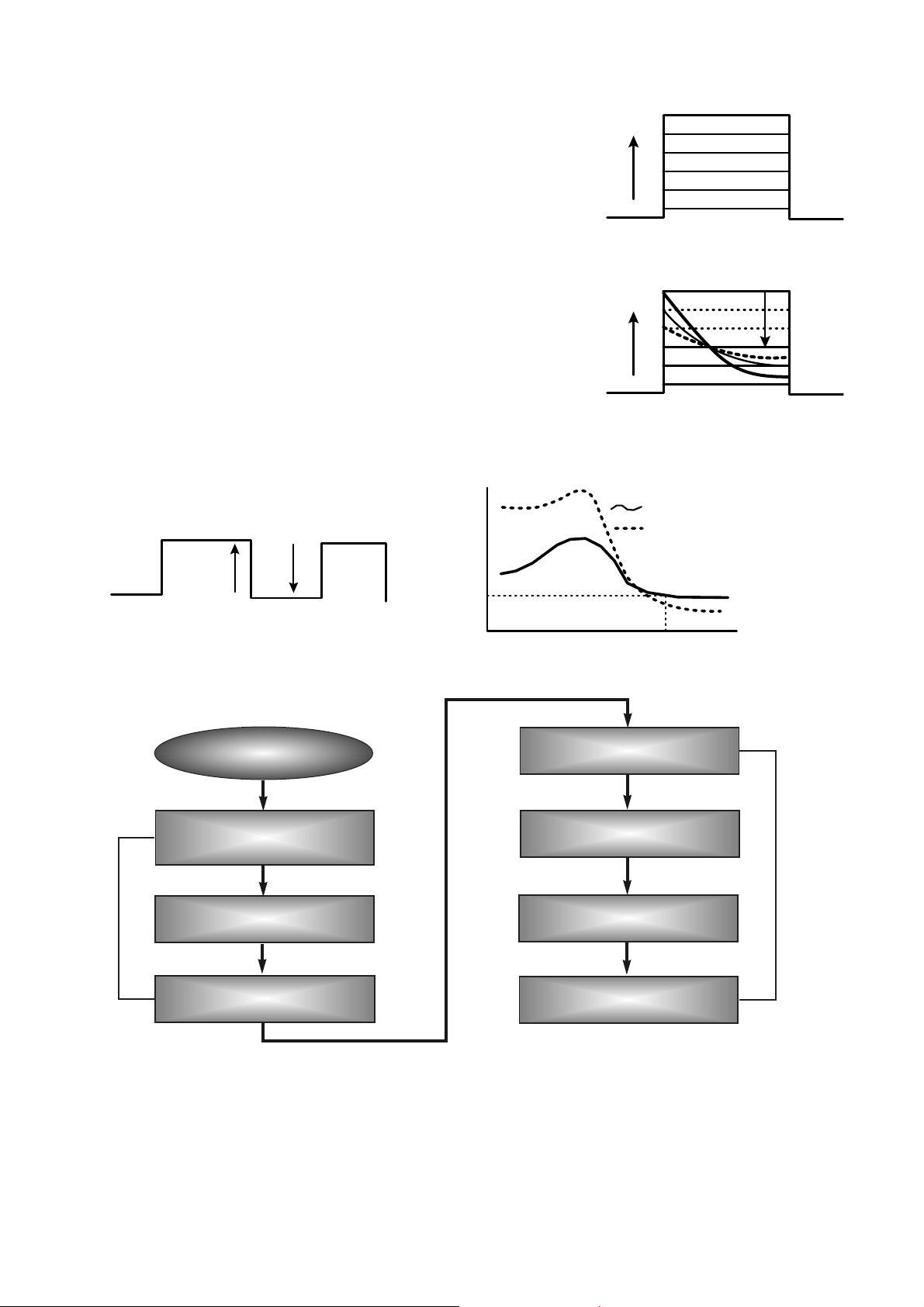
Incident recording pulse
Reflected recording pulse
Sampled timing B
11T
Sample B-level (Write Power)
Level B
Sampled at timing B
Pwo decided by OPC
Recording Power
Level B with Pwo
normalized to recording power
Sample Disc Reflectivity
(Read power)
10. Writing Process of DISC
INTERNAL STRUCTURE OF THE PICK-UP
1. Inner Circuit of the PICK-UP
19
J1-1
J2-1 T-
J2-2 F-
J2-3 T+
J2-4 F+
J1-2
J1-3
J1-4
J1-5
J1-6
J1-7
J1-8
J1-9
J1-10
J1-11
J1-12
J1-13
J1-14
J1-15
J1-16
J1-17
J1-18
J1-19
J1-20
J1-21
J1-22
J1-23
J1-24
J1-25
J1-26
J1-27
J1-28
J1-29
J1-30
T-
F-
T+
F+
GND1
GND2
IIN2
IIN3
GND
OUTEN3
OUTEN2
GND3
IINR
VOUT1
Vref
FE4(B)
FE3(C)
FE2(D)
FE1(A)
Vcc1(HPN)
Vc
GND4
OSCEN
ENABLE
Vcc2(DRV)
GND5
E
F
G
H
R1
R5
R2
4.7k
R33
0.1u
1k
C7
R39
0.1V C2
2
LD(-)
HIJH7247
IJ4
VCC
A
C
FE1
FE2
FE3
FE4
VC
PHTDGND
LD(+)EFGH
MON
R10
C1 0.1u
C11
C8
0.1U
R37 8.2k
C27
B5052
IJ15
4p
51k
15k
8
9
10
11
12
13
14
8
9
1011121314
1
2
3
4
5
6
7
15
7
6
5
4
3
2
1
15k
C5
C4
C6 D.1U
C3
VCO1
OSCEN
ENABLE
RAMP
GND1
OUT
VCO2
PDIN
OUTEN3
OUTEN2
IIN3
IIN2
RFREQ
IINR
VREF
VOUT
• Focus Error = (A+C) - (B+D)
• Dpp = {(A+D)-(B+C)} - k{(E+G) - (F+H)}
2. Signal detection of the P/U
1) Focus Error Signal ==> (A+C)-(B+D)
This signal is generated in RF IC (IC402 : CXA3558R) and controls the pick-up’s up and down to focus on
Disc.
2) Tracking Error Signal (DPP Method) ==> {(A+D)-(B+C)}- kx {(F+H)-(E+G)}
This signal is generated in RF IC (IC402 : CXA3558R) and controls the pick-up’s left and right shift to find
to track on Disc.
3) RF Signal ==> (A+B+C+D)
This signal is converted to DATA signal in DSP IC (IC102 : OTI-9796).
20
Pick-Up module
Photo Diode
Tracking
Focusing
Infrared Iaser
k[(F+H) - (E+G)]
(A+D) - (B+C)
(A+D) - (B+C) - k[(F+H) - (E+G)]
Offset
TE
Tp
Sub2
Main
Tp/2
Sub1
Track Center
F, E
D,C
A,B
H,G
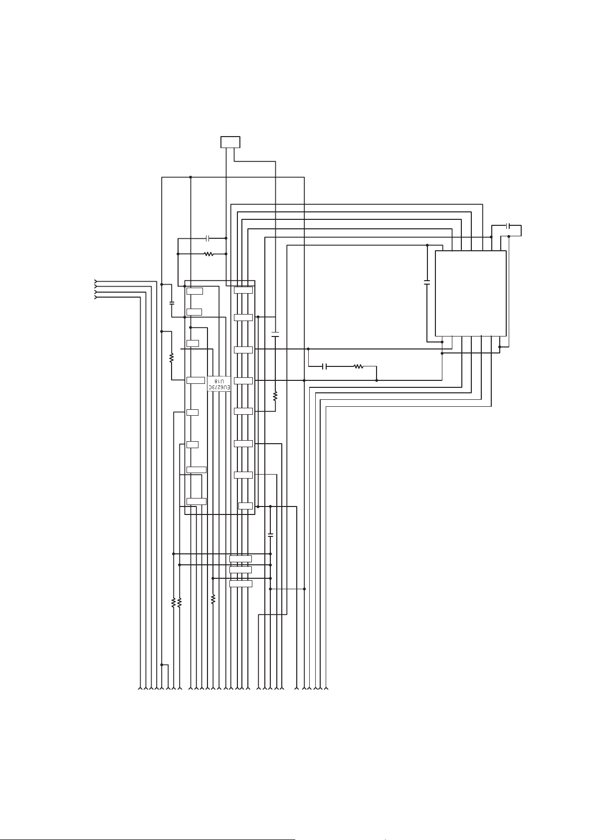
DESCRIPTION OF CIRCUIT
1. ALPC (Automatic Laser Power Control) Circuit
1-1. ALPC Loop Circuit
21
FPDO
VRDCN
VRDC
RREF1
RREF2
VWDCN
WREF
FPDO
RFPDSH
SRDC
FVREF
WFPDSH
SWDC
WLDON
WR/RE
APCCSW
VWDC
VRDC
Q400 Q401
0.15u
1M
1K
C410
150P
R434
R405
R415
R403
R404
8200P
470
10K
C410
R406
150P
1M
R442
R419
C427
C431
C435
R444
C428
FW-REC
VWDC
VWDC
OUTEN3
OUTEN2
LDON
LDON
OUTEN2
OUTEN3WGATE
CON400
P/U
IC403
DAC
IC102 OTI9796
VREF
(FVREF)
RLDON
RREFSW
APCCSW
WRITEG
WFPDG
S/H
Delay
LDLMTC
-8~+7.75dB
0.25dB step
R7 "1":ON
R9
5k
R1
20k
R2
20k
R3
20k
R8
20k
R6
20k
C5
100p
R12
10k
R10
H:OFF
L:ON
H:ON
L:OFF
5k
R4
20k
R5
20k
R11
10k
S2
S5
S3
S4
S1
_
+
_
+
_
+
_
+
+
+
20k "0": GND
GND
GND
GND
GND
GND
(Read)
(Write)
REPDG
20dB/26dB
VRGSW
MPXOUT
(testmode)
MPXOUT
(testmode)
S/H
Gain
adj.
typ. 0/6dB
99
32
1
100
31
1
2
46
73
19
3
4
18
3
4 29
31
30
5
6
7
9
8
10
23
184
183
141
27
26
39
166

1-2. ALPC(Automatic Laser Power Control) Circuit Operation
This circuit consists of Feedback Loop to maintain light output of the Laser Diode(FPDO).
Feedback signal, output voltage from PD(Photo Detector) of P/U, is used monitor the light power of
Laser Diode.
1) Read Loop
RREF(Read Reference Voltage) of IC402(CXA3558) Pin 5,6, which is from DAC(IC403) Pin 18,19, is
the reference level of the Read Loop part of this ALPC Circuit.
• When Playback
VRDC(Pin 4) signal of IC402(CXA3558) is output to P/U through Gain Control S/W and drives Laser
Diode during play back.
This S/W Ciruit is designed to reduce transition time from CD-RW writing mode to playback mode.
• When writing mode
- CD-R
Three Laser Power Levels, Read, Write, and Overwrite, are used to write on CD-R disc, and Read
Level is used to monitor the output laser power.
For stabilizing read loop, the S/H signal(RFPDSH), which sample and hold the Read Level of laser
power in the CD-R writing mode, is input through Pin 32 of CXA3558.
- CD-RW
Three Laser Power Levels, Read, Erase and Write, are used to write on CD-RW disc, and Erase
Level is used, during CD-RW writing, to monitor output laser power.
It is not VRDC but VWDC that is the output signal of the control loop performed by Erase level.
2) Write Loop
For stabilizing write Loop, the S/H signal(WFPDSH), which sample and hold the Erase Level of laser
power in the CD-RW writing mode, is input through Pin 31 of CXA3558.
Output voltage of Write Loop, VWDC(Pin 8 of CXA3558), is protected by the high limit diode applied to
P/U.
In the writng mode, the reference signal of Write Loop is WREF(Pin 3&4 of IC403)and it is input to Pin 10
of IC402(CXA3558).
22
2. RF Amplifier Circuit
Block Diagram
23
off set adj
(B+C)-(A+D)
2((A+D)-(B+C))
4((F+H)-(E+G))
2((A+D)-(B+C))
A+B+C+D
Gain Adj
LPF
(100KHz)
FE
TE
RRF
58
IC101 197
A,B,C,D
90 91 92
93
LPF (40kHZ)
18
CEO
IC101 204
LPF
(200KHz)
LP F
(200KHz)
E,F,G,H
99 98
97
96
Gain Adj
LPF
28
IC101
198
IC101
194
Gain Adj
Gain Adj
Gain Adj
HPF
(1kHz)
HPF
HPF
82
67
EQRFP
IC101
163
(10KHz)
BPF AGC
30
AGC
HPF
(10kHz)
ATFG
IC101
132
CXA 3558R
PDIC
VC
GND
3.8V
LPH-321A
+
-
OTI-9796
15
57
Offset adj
Offset adj
Offset adj
X0.5
X0.25
3. Focus/Tracking/Sled Servo Circuit
3-1. Focus, Tracking & Sled Servo Process
24
Focus, Tracking Servo
C
B
D
A
E
F
G
H
Pick- up
A,B,C,D,E,F,G,H
A,B,C,D
Focus Error
Detector
Track Error
Detector
A,B,C,D
E,F,G,H
IC402 CXA3558R
FE
TE
TE FE
A/D
Low freq Gain Filter
Digital
EQ
DAC
Sled Co ntrol
Signal
IC102
Servo Control
OTI9796
LEVEL SHIFT
LEVEL SHIFT
Tracking Focus ing
Actuator
FAO
TAO
F+
F-
T+
T-
IC201
u-COM
Sled Co ntrol
M
SLED MOTOR
SLO
LEVEL SHIFT
SLO+
IC503
BA5929FP
SLO-
IC403
BU2500FV
(DAC)
A/D
IC503 BA5929FP

3-2. Focus Servo
The aim of Focus Servo is to maintain the distance between object lens of P/U and disc surface, so that
the detected RF signals (A, B, C, D) can be maximized.
Focus Servo is based on focus error (FE) signal which is generated from focus error detection block in
CXA3558 (IC402) using Astigmatism Method. Focus gain and path can be changed at the CXA3558
according to the disc, and the resulting output (FE) is input to Servo IC (IC102, OTI-9796).
FE signal after first amplification in OTI-9796 is A/D converted and input to Digital Equalizer Block, most
important part at the Focus Servo. At the Digital Equalizer, adjustments for Focus Bias and Loop Gain are
performed.
After D/A converted, Focus servo signal is output through FDO port (OTI-9796, Pin 207) and drive Focus
Actuator through the Focus Drive IC (IC503, BA5929FP).
3-3. Tracking Servo
The aim of Tracking Servo is to make laser beam trace the data track on disc. Tracking Error (TE) signal
is generated from tracking error detection block in CXA3558 (IC402) using DPP (Differential Push-Pull)
Method. DPP method uses not only main beam (A, B, C, D) but side beams (E,F and G, H) for correcting
DC offset generated in Push-Pull method.
The remaining procedures of TE signal processing in OTI-9796 is similar to Focus Servo.
After D/A converted, Tracking servo signal is output through TDO port (OTI-9796, Pin 208) and drive
Tracking Actuator through the Tracking Drive IC (IC503, BA5929FP).
3-4. Sled Servo
The working distance of tracking actuator is too short to cover whole disc radius. Sled Servo make PU
move by little and little so that the laser beam keep tracing the data track on disc continuously when
tracking actuator reaches the working limit.
Another function of Sled Servo is to seek a target point on disc, following user commands.
SLD move of BW2500FV is generated in µ-com. SLD+, SLD- are output to sled motor via IC503
(BA5929FP).
25
6
DISASSEMBLY
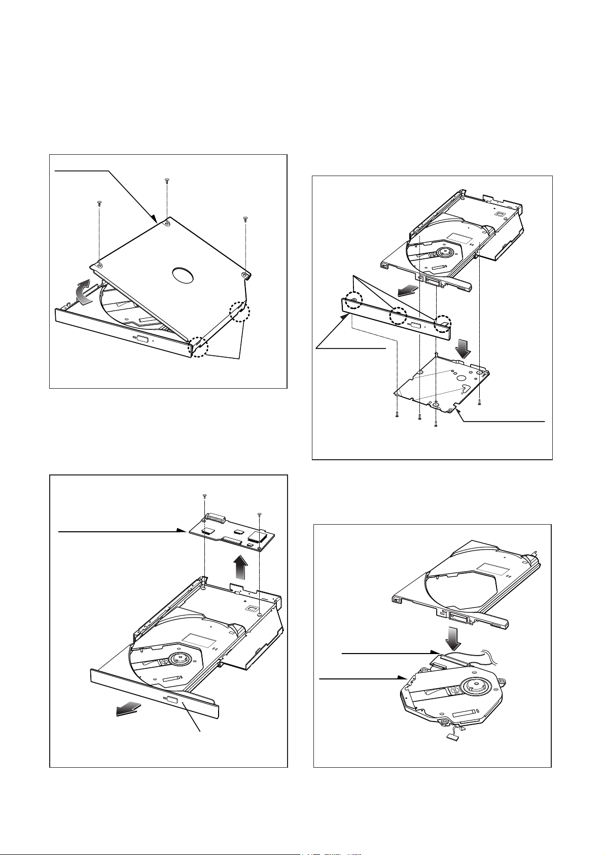
1. CABINET
A. Release 3 screws (A).
B. Lift up the Cabinet in the direction of arrow (1).
(See Fig.1)
2. MAIN CIRCUIT BOARD
A. Insert and press a rod in the Emergency Eject Hole and
then the CD Tray will open in the direction of arrow (2).
B. Release 2 screws (B).
C. Remove the Main Circuit Board.
3. FRONT PANEL
A. Remove the Front Panel.(The Front Panel is a snap on
type.)
B. At this time, be careful not to damage the 3 hooks (a) of
the it. (See fig.3)
C. Release 4 screws (C) and remove the Cover Bottom (3).
4. BASE PICK-UP
A. Remove the FPC Cable. At this time, the FPC connector
must be pulled in the direction of Front carefully.
B. Remove the Base Pick-up (4).
(1)
(A)
(A)
(A)
CABINET
2 HOOKS
HOOKS (a)
FRONT PANEL
COVER BOTTOM
BASE PICK-UP
FPC CONNECTOR
MAIN CIRCUIT BOARD
EMERGENCY EJECT HOLE
Fig.1
Fig.3
Fig.2
Fig.4
(2)
(3)
(C)
(C)
(C)
(C)
(2)
(B)
(B)
(4)

ATIP Absolute Time in Pre-groove. With an additional modulation of the “Wobble”, the “Groove” contains a time
code information.
Wobble The pre-groove in the Disc is not a perfect spiral but is wobbled.
With : – A typical amplitude of 30 nm
– A spatial peried of 54~64 µm
CW Continuous Wave. The laser light output is at a constant level.
DOW Direct Over-Write. The action in which new information is recored over previously recorded information in
CD-RW disc.
Overwrite
The action in which new information is recorded over previously recorded information.
(Pre-)Groove
The guidance track in which clocking and time code information is stored by means of an FM
modulated wobble.
Land Land is characterized in the following way:
When radial signals are concerned,land is defined as the area between the grooves.
When HF signal are concerned,land is defined as the area between the marks(pits) in tangential
direction.
Hybrid Disc A Multisession disc of which the first Session is mastered. On a hybrid disc, recorded and
mastered information may co-exist.
Mastered Information,stored as pits on the disc during the manufacturing process of the disc.
Information (when making the master)
OPC Optimum Power Control. Procedure is determined optimum recording power according to CD-
R/RW Media in recording start step.
ROPC Running OPC. The purpose is to continuously adjust the writing power to the optimum power
that is required.
When the optimum power may change because of changed conditions of disc and change in
operating temperature.
Jitter The 16 value of the time variation between leading and trailing edges of a specific (I3 … I11) pit
or land as measured by Time Interval Analysis.
Deviation The difference between a fixed value of Pit length and Land length.
TOC Table Of Contents : in the Lead-in Area the subcode Q-channel contains information about the
Tracks on the disc.
Packet A method of writing data on a CD in small increments.
Writing Two kinds of packets can be written : Fixed-length and Variable-length.
Write The shape of the HF write signal used to modulate the power of the laser.
Strategy The Write Strategy must be used for recordings necessary for disc measurements.
Information Wobble, ATIP, Disc Identification, Write Power, Speed Range OPC Parameters, etc are
Area recorded in the Information area of CD-RW Disc
Finalization The action in which (partially) unrecorded or logically erased tracks are finished and the Lead-in
and/or Lead-out areas are recorded or overwritten with the appropriate TOC subcode.
Logical Erase
A method to remove information from a disc area by overwriting it with an EFM signal containing
mode 0 subcode
A logically erased area is equivalent to an unrecorded
Physical Erase
The action in which previously recorded information is erased by overwriting with a CW laser
output.
After a Physical Erase action, the erased area on the CD-RW disc is in the unrecorded state
again.
Session
An area on the disc consisting of a Lead-in area, a Program area, a lead-out area.
Multi session
A session that contains or can contain more than one session composed Lead-in and Lead-out
GLOSSARY
7
TROUBLESHOOTING GUIDE
Are the pin 38
~ 42 of CON100 +5V respectively
after the power cable
connecting?
Reset or Power Check.
• Check the power(5V) short.
• Check the PC power cable.
• Repair the PC power supply.
• Check the IC105(RESET IC).
• Check the IC201(µ-com).
Does the pin 75
of IC102 change from0V to 5V at
the power supply initial input
mode?
• Is the pin 3 of
IC100 and IC106 3.3V?
• Is the pin 4 of IC101 2.5V?
• Is the pin 3 of IC400 1.65V?
NO
NO
YES
YES
YES
53
Is the X201 and X301 oscillating?
• Check the X201 and X301.
• Check the IC102.
NO
• Check the IC100 and IC106.
• Check the IC101 and IC400.
NO
Check it after connecting the power cable
only for NO Reset or Power ON.
YES
OK
54
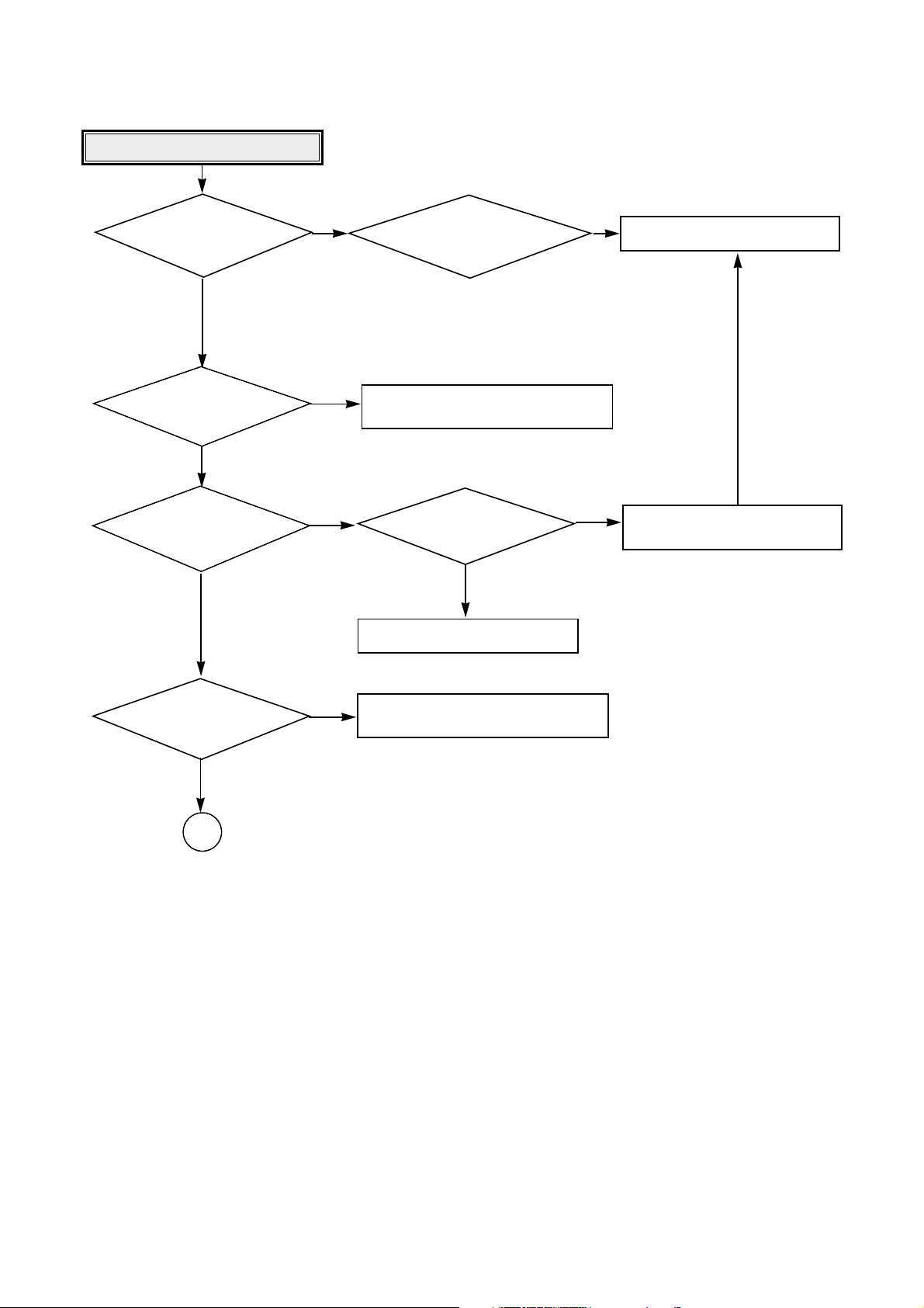
System Check.
Go to “Sled operating is abnormal”
Load tray without inserting disc.
NO
Does Pick-up move to inside?
Does Spindle Motor
rotate in a moment?
Does Laser turn on?
After eject tray, Insert CD-ROM Disc
and reloading.
Does Disc stop?
Does Disc rotate
continuously as Disc recognition is
abnormal?
After eject tray, Insert CD-R Blank Disc
and reloading.
Does Disc rotate
continuously as Disc recognition is
abnormal?
Does Disc stop?
Go to “Spindle motor operating is
abnormal”
Go to “Laser is abnormal”
Go to “Spindle control is abnormal 1”
Go to “Spindle control is abnormal 2”
Go to “Spindle control is abnormal 3”
Go to “RF output is abnormal”
NO
NO
YES
NO
NO
NO
NO
YES
YES
YES
YES
YES
YES
YES
Does Lens move
Up/Down?
Go to “Focus Actuator operating is
abnormal”
NO
YES
OK
55
Is there Sled
control signal output?
(IC403 pin 8)
Sled operating is abnormal.
Replace the IC501 (BA5929).
Replace the IC102(MICOM).
Aren’t DRV_ MUTE signal
“L”?(IC503 pin 17)
• Check the connction of IC503 pin 5.
• Replace the IC503(BA5929).
• Check the connction of CON400.
• Replace the Sled Motor.
Check the connection of IC201
pin 29.
Is there Sled FG signal
input? (IC102 pin 53)
YES
•
Check the
connecting line of IC403 pin8.
NO
NO
YES
YES
NO
Is there
Sled drive voltage input?
(IC503 pin 5)
YES
NO
Is there
Sled drive voltage output?
(IC503 pin 11, 12)
YES
YES
OK
 Loading...