

LG FM21AH UE3, FM30AH UE3, FM25AH UE3, FM27AH UE3, FM38AH UH3 Svc Manual
...
Multi Air Conditioner
SVC MANUAL(General)
MODEL : Multi-Inverter Type
CAUTION
Before Servicing the unit, read the safety precautions in General SVC manual.
Only for authorized service personnel.
Internal Use Only
http://biz.lgservice.com

- 1 -
Copyright ©2007 LG Electronics. Inc. All right reserved.
Only for training and service purposes
LGE Internal Use Only
Air Conditioner Service Manual
CONTENTS
Part 1 General Information.........................................................................................................2
1. Safety Precautions........................................................................................................3
2. Model Line Up................................................................................................................6
3. Nomenclature ..............................................................................................................11
Part 2 Functions & Controls.....................................................................................................13
1. List of Functions & Controls......................................................................................14
2. Air Flow .......................................................................................................................16
3. Air Purifying.................................................................................................................18
4. Installation Functions.................................................................................................19
5. Reliability .....................................................................................................................23
6. Convenience Functions & Controls .........................................................................24
7. Special Function & KIT...............................................................................................36
Part 3 Control logic....................................................................................................................39
1. Compressor.................................................................................................................40
2. Step(frequency) control..............................................................................................42
3. Reversing valve operaton ..........................................................................................43
4. Discharge pipe control ...............................................................................................44
5. Input Current Control..................................................................................................45
6. Outdoor Fan Control...................................................................................................46
7. Defrost Control............................................................................................................47
8. LEV Control .................................................................................................................48
9. Oil restoration operation ............................................................................................50
10. Compressor warm-up control logic ........................................................................50
11. Heat sink control.......................................................................................................51
Part 4 Test Run..........................................................................................................................52
1. Check before Test Run ..............................................................................................53
2. Test Run Flow chart ...................................................................................................54
3. Test Runing..................................................................................................................55
Part 5 Trouble Shooting Guide ...............................................................................................58
1. Self-diagnosis Function ......................................................................................59
2. Pump Down ..........................................................................................................63
3. Evacuation............................................................................................................64
4. Gas Charging .......................................................................................................65
5. Cycle Part .............................................................................................................66
6. Electronic Parts....................................................................................................67

- 2 -
Copyright ©2007 LG Electronics. Inc. All right reserved.
Only for training and service purposes
LGE Internal Use Only
1. Safety Precautions ............................................................................................................3
2. Model Line Up .....................................................................................................................6
3. Nomenclature....................................................................................................................11
Part 1 General Information
Part 1 General Information
- 3 -
Copyright ©2007 LG Electronics. Inc. All right reserved.
Only for training and service purposes
LGE Internal Use Only
1. Safety Precautions
1.1 Cautions in Repair
To prevent injury to the user or other people and property damage, the following instructions must be followed.
■ Incorrect operation due to ignoring instruction will cause harm or damage. The seriousness is classified by the following indications.
This symbol indicates the possibility of death or serious injury.
This symbol indicates the possibility of injury or damage to properties only.
■ Meanings of symbols used in this manual are as shown below.
Be sure not to do.
Be sure to follow the instruction.
Dangerous Voltage
Be sure to disconnect the power cable plug from the plug socket before disassembling the equipment for a repair.Internal components and circuit boards are at
main potential when the equipment is connected to the power cables. This voltage is extremely dangerous and may cause death or severe injury if come in contact with it.
Do not touch the discharging refrigerant gas during the repair work.
The discharging refrigerant gas.The refrigerant gas can cause frostbite.
Release the refrigerant gas completely at a well-ventilated place first.
Otherwise, when the pipe is disconnected, refrigerant gas or refrigerating
machine oil discharges and it Can cause injury.
When the refrigerant gas leaks during work, execute ventilation. If the refrigerant
gas touches to a fire, poisonous gas generates. A case of leakage of the refrigerant and the closed room full with gas is dangerous because a shortage of oxygen
occurs. Be sure to execute ventilation.
When removing the front panel or cabinet, execute short-circuit and discharge
between high voltage capacitor terminals. If discharge is not executed, an electric
shock is caused by high voltage resulted in a death or injury.
Do not turn the air-conditioner ON or OFF by plugging or unplugging the power
plug. There is risk of fire or electrical shock.
Part 1 General Information
- 4 -
Copyright ©2007 LG Electronics. Inc. All right reserved.
Only for training and service purposes
LGE Internal Use Only
Do not turn on the breaker under condition that front panel and cabinet are
removed.
Be sure to earth the air conditioner with an earthing conductor connected to the
earthing terminal.
Conduct repair works after checking that the refrigerating cycle section has
cooled down sufficiently. Otherwise, working on the unit, the hot refrigerating
cycle section can cause burns.
Do not tilt the unit when removing panels. Otherwise, the water inside the unit
can spill and wet floor.
Do not use the welder in a well-ventilated place. Using the welder in an enclosed
room can cause oxygen deficiency.
Be sure to turn off power switch before connect or disconnect connector, or parts
damage may be occurred.
Do not use a defective or underrated circuit breaker. Use the correctly rated
breaker and fuse. Otherwise there is a risk of fire or electric shock.
Install the panel and the cover of control box securely. Otherwise there is risk of
fire or electric shock due to dust, water etc.
Indoor/outdoor wiring connections must be secured tightly and the cable should
be routed properly so that there is no force pulling the cable from the connection
terminals. Improper or loose connections can cause heat generation or fire.
Do not touch, operate, or repaire the product with wet hands. Hoding the plug by
hand when taking out. Otherwise there is risk of electric shock or fire.

Part 1 General Information
- 5 -
Copyright ©2007 LG Electronics. Inc. All right reserved.
Only for training and service purposes
LGE Internal Use Only
1.2 Inspections after Repair
Check to see if the parts are mounted correctly and wires are connected.
Improper installation and connections can cause an electric shock or an injury.
Check the installation platform or frame has corroded. Corroded installation platform or frame can cause the unit to fall, resulting in injury.
Be sure to check the earth wire is correctly connected.
After the work has finished, be sure to do an insulation tset to check the resistance is 2[Mohm] or more between the charge section and the non-charge metal
section (Earth position). If the resistance value is low, a disaster such as a leak or
electric shock is caused at user’s side.
Check the drainage of the indoor unit after the repair. If drainage is faulty the
water to enter the room and wet floor.
Check to see if the power cable plug is not dirty or loose. If the plug is dust or
loose it can cause an electrical shock or fire.
Do not use a joined power cable or extension cable, or share the same power
outlet with other electrical appliances. otherwise, it can cause an electrical shock,
excessive heat generation or fire.
Do not insert hands or other objects through the air inlet or outlet while the product is operating. There are sharp and moving parts that could cause personal
injury.
Do not block the inlet or outlet of air flow. It may cause product failure
2. Model Line Up
Part 1 General Information
- 6 -
Copyright ©2007 LG Electronics. Inc. All right reserved.
Only for training and service purposes
LGE Internal Use Only
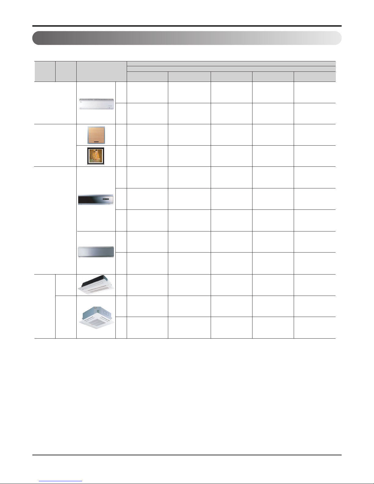
2.1 Indoor units
2.05
(7)
2.64
(9)
3.52
(12)
5.28
(18)
7.03
(24)
ART COOL
SP1
SF
AMNH096AP*1
[MA09AH* NP1]
AMNH09GAF*1
[MA09AH* NF1]
AMNH12GAF*1
[MA12AH* NF1]
AMNH126AP*1
[MA12AH* NP1]
SZ
SU
S3
1-way
TE1
AMNH09GTEF0
[MT10AH NE1]
AMNH12GTEF0
[MT12AH NE1]
AMNH18GTEF0
[MT18AH NE1]
Category Type
Model names
Capacity, kW(kBtu/h)
Chassis
Wall mounted
ART COOL
Mirror
4-way
Ceiling
cassette
S4
AMNH07GD4L0
[MS07AH N40]
AMNH12GD4L0
[MS12AH N40]
S5
AMNH18GD5L0
[MS18AH N50]
AMNH24GD5L0
[MS24AH N50]
AMNH07GDZ*0
[MC07AH* NZ1]
AMNH12GDU*0
[MC12AH* NU1]
AMNH18GD3*0
[MC18AH* N31]
AMNH24GD3*0
[MC24AH* N31]
SE
S8
AMNH09GDE*1
[MC09AH* NE1]
AMNH18GD8*1
[MC18AH* N81]
AMNH24GD8*1
[MC24AH* N81]
AMNH07GDE*1
[MC07AH* NE1]
AMNH12GDE*1
[MC12AH* NE1]
TC1
AMNH09GTCC0
[MT09AH NC1]
AMNH12GTCC0
[MT11AH NC1]
TH
AMNH24GTHF0
[MT24AH NH0]
AMNH09GDU*0
[MC09AH* NU1]
AMNH09GD4L0
[MS09AH N40]
* indicates color of panel(B:Blue, C:Cherry, D:Wood, M:Metal, R:Mirror, V:Silver, W:White wood, E:Red, G:Gold,
H:White Silver, 1:KISS)
Part 1 General Information
- 7 -
Copyright ©2007 LG Electronics. Inc. All right reserved.
Only for training and service purposes
LGE Internal Use Only
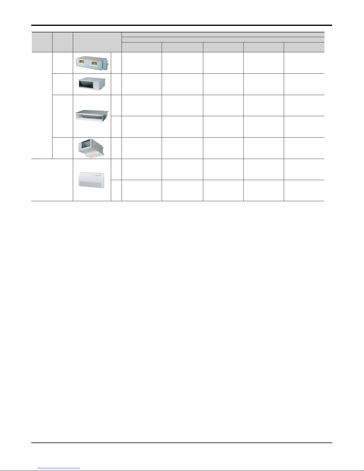
B1
AMNH09GB1A0/1
[MB09AHL N10/1]
AMNH12GB1A0/1
[MB12AHL N10/1]
B2
AMNH18GB2A0/1
[MB18AHL N20/1]
AMNH24GB2A0/1
[MB24AHL N20/1]
Low
static
pressure
(Slim)
Category Type
Model names
Capacity, kW(kBtu/h)
Chassis
2.05
(7)
2.64
(9)
3.52
(12)
5.28
(18)
7.03
(24)
BH
AMNH186BHA0
[MB18AH NH0]
AMNH246BHA0
[MB24AH NH0]
Low
static
pressure
BT
AMNH096BTG0
[MB09AHL NT0]
AMNH126BTG0
[MB12AHL NT0]
AMNH186BTG0
[MB18AHL NT0]
Built in
BP
AMNH096BPA0
[MB09AHB NP0]
AMNH126BPA0
[MB12AHB NP0]
VE
AMNH096VEA0
[MV09AH NE0]
AMNH126VEA0
[MV12AH NE0]
VB
AMNH186VBA0
[MV18AH NB0]
AMNH246VBA0
[MV24AH NB0]
High
static
pressure
Ceiling & floor
Ceiling
concealed
duct

Part 1 General Information
- 8 -
Copyright ©2007 LG Electronics. Inc. All right reserved.
Only for training and service purposes
LGE Internal Use Only
Heat pump
A2UW146FA3
[FM15AH UL3]
A2UW166FA0
[FM17AH UL0]
A2UW166FA1
[FM17AH UL1]
A3UW186FA0
[FM19AH UE0]
No. of connectable indoor units Max.2 Max.3
Total capacity index of connectable kW 6.15 7.03 8.79
indoor units kBtu/h 21 24 30
Power supply 1ø, 220-240V, 50Hz
Chassis
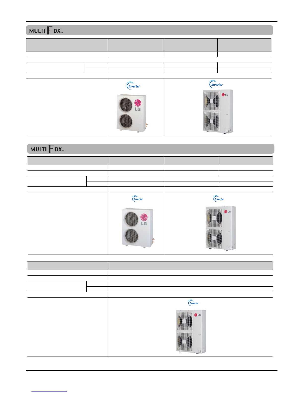
2.2 Outdoor units
Heat pump
A3UW216FA3 [FM21AH UE3] A4UW246FA3 [FM25AH UE3] A4UW276FA3 [FM27AH UE3]
No. of connectable indoor units Max.3 Max.4
Total capacity index of connectable kW 9.67 11.4 12.0
indoor units kBtu/h 33 39 41
Power supply 1ø, 220-240V, 50Hz
Chassis
Heat pump
A5UW306FA3 [FM30AH UE3] A5UW406FA3 [FM38AH UH3]
No. of connectable indoor units Max.5
Total capacity index of connectable kW 14.1 15.2
indoor units kBtu/h 48 52
Power supply 1ø, 220-240V, 50Hz
Chassis
Part 1 General Information
- 9 -
Copyright ©2007 LG Electronics. Inc. All right reserved.
Only for training and service purposes
LGE Internal Use Only
Heat Pump
A6UW368FA0[FM37AH UE0] A7UW428FA3[FM41AH U33] A8UW488FA3[FM49AH U33]
No. of connectable indoor units Max.6 Max.7 Max.8
Number of BD units to be connected Max.2
Total capacity index of connectable kW 13.5 15.8 18.2
indoor units kBtu/h 46 54 62
Power supply 3ø, 380-415V, 50Hz
Chassis
Heat Pump
A9UW548FA3[FM57AH U33]
No. of connectable indoor units Max.9
Number of BD units to be connected Max.3
Total capacity index of connectable kW 21.4
indoor units kBtu/h 73
Power supply 3ø, 380-415V, 50Hz
Chassis
(3 phase)
Heat Pump
A7UW406FA3
[FM40AH UH3]
A8UW486FA3
[FM48AH U33]
A9UW566FA3
[FM56AH U33]
No. of connectable indoor units Max.7 Max.8 Max.9
Number of BD units to be connected Max.2
Total capacity index of connectable kW 15.2 18.2 21.4
indoor units kBtu/h 52 62 73
Power supply 1ø, 220-240V, 50Hz
Chassis
(1 phase)
Part 1 General Information
- 10 -
Copyright ©2007 LG Electronics. Inc. All right reserved.
Only for training and service purposes
LGE Internal Use Only
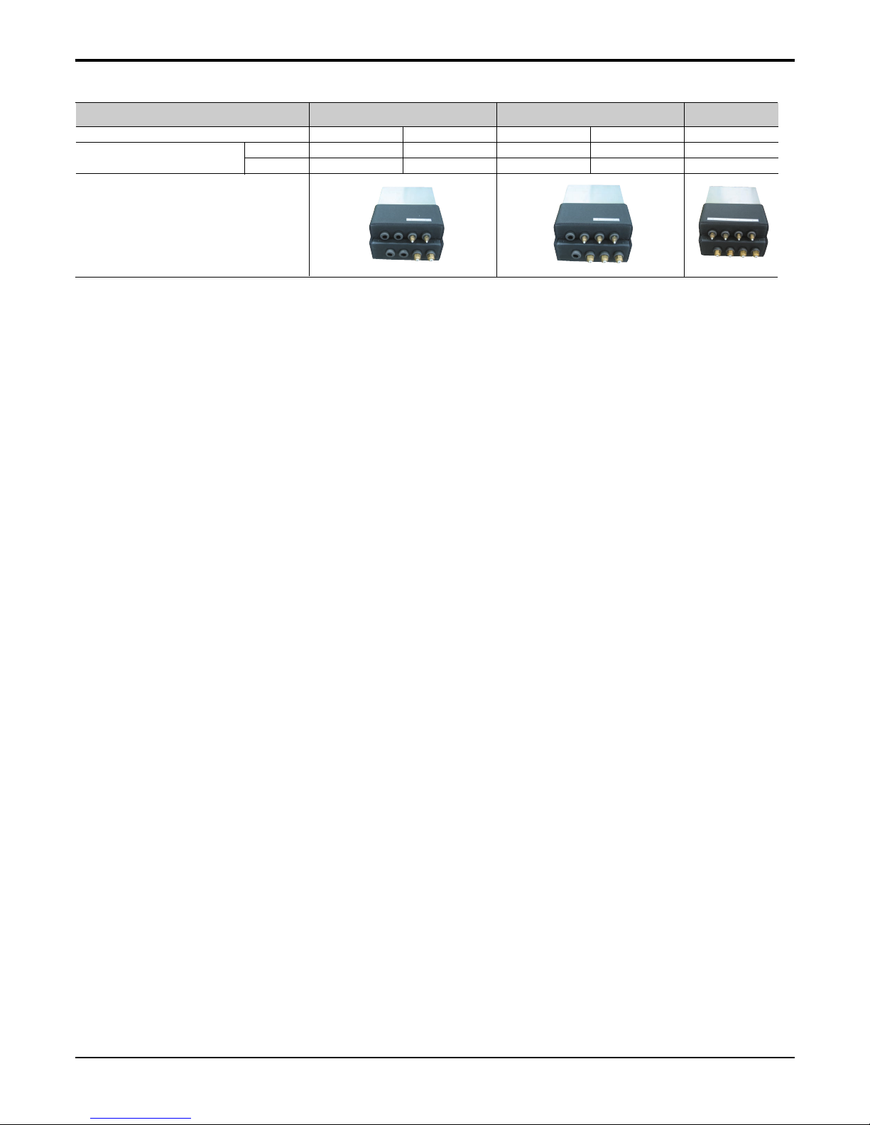
No. of connectable indoor units
Max. 2 Max. 3 Max. 4
Model name PMBD3620 PMBD7220 PMBD3630 PMBD7230 PMBD3640
Connectable indoor unit capacity kW 2.05~7.03 5.28~10.6 2.05~7.03 5.28~10.6 2.05~7.03
kBtu/h 7~24 18~36 7~24 18~36 7~24
BD unit
2.3 BD(Branch distributor) units
Part 1 General Information
3. Nomenclature
3.1 Indoor Unit(Global)
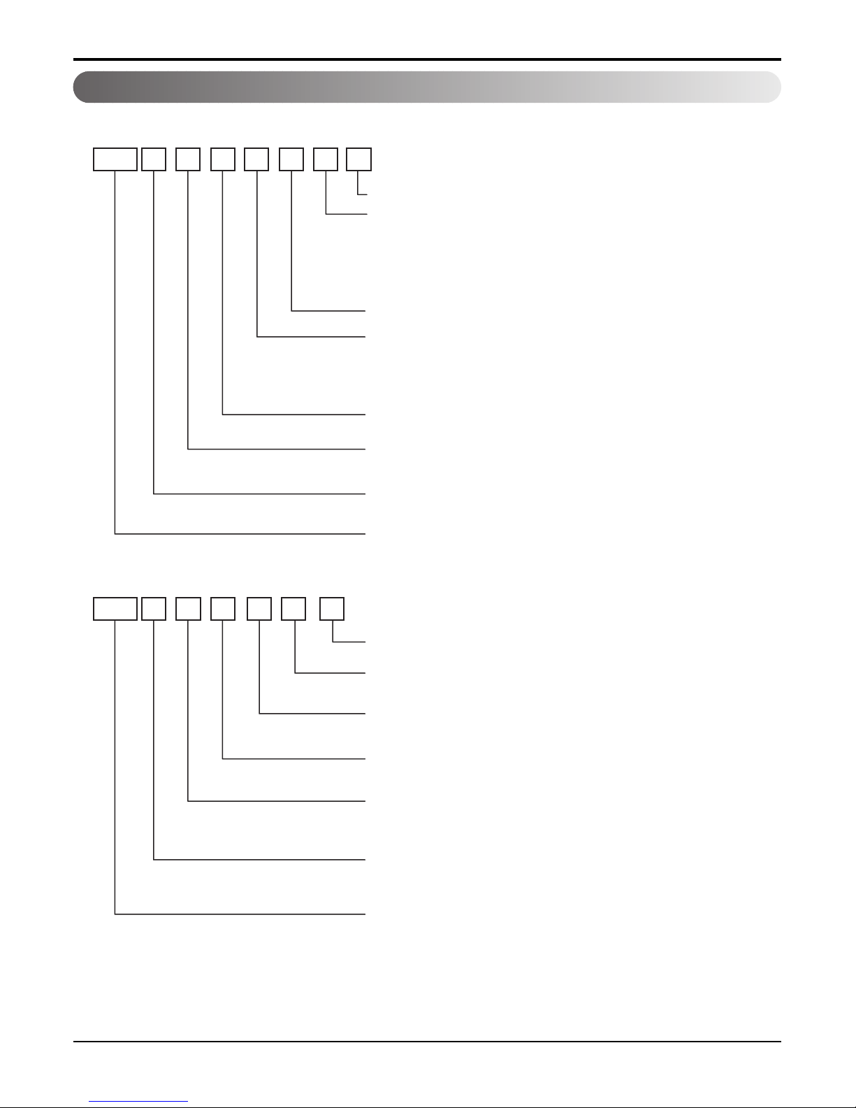
3.2 Outdoor Unit(Global)
AMN H G
07
4DL0
Serial number
A4U W 624 F A 3
Electrical rating
Indicates that this is multi system indoor unit using R410A
Model type
H : Heat pump
Ex) 7,000 Btu/h → '07', 18,000 Btu/h → '18'
Cooling/heating capacity
Electrical rating
6 : 1ø, 220-240V, 50Hz G: 1ø, 220-240V, 50Hz/60Hz
Chassis name
Indoor unit type
L : Wall Mounted , A : ART COOL
D : ART COOL Mirror, T : Ceiling cassette
B : Ceiling concealed duct
V : Ceiling & floor
Function
A : Basic, L : Nano plasma (Wall Mounted)
C: Plasma(ceiling cassette), G: Low static motor
ART COOL(Mirror) type front panel color
B : Blue, C : Cherry, D : Wood, M : Metal, R : Mirror, V : Silver,
W : White wood, E : Red, G : Gold, H:White Silver, 1 : KISS
Indicates that this is multi system outdoor unit using R410A
Ex) A4U : Connectable max. 4 indoor units
A6U : Connectable max. 6 indoor units
Model type
W : DC inverter heat pump
Ex) 24,000 Btu/h → '24', 48,000 Btu/h → '48'
Cooling/heating capacity
6 : 1ø, 220-240V, 50Hz
8 : 3ø, 380-415V, 50Hz
Multi type
Function
A : Basic
F : Free joint multi type
Serial number
- 11 -
Copyright ©2007 LG Electronics. Inc. All right reserved.
Only for training and service purposes
LGE Internal Use Only
- 12 -
Copyright ©2007 LG Electronics. Inc. All right reserved.
Only for training and service purposes
LGE Internal Use Only
Part 1 General Information
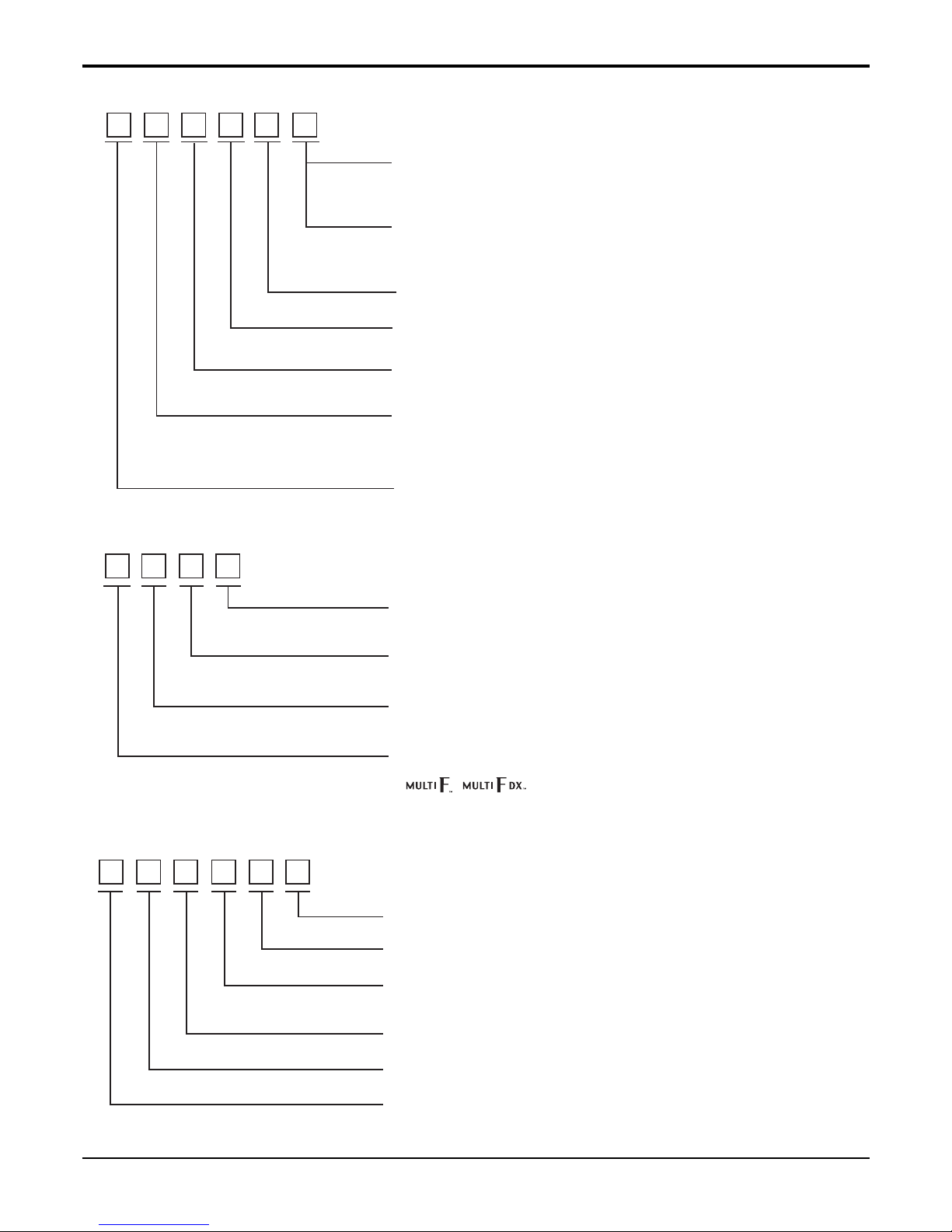
3.3 Indoor Unit(Europe)
3.5 BD Unit(Global)
MC12AHB
Color of front panel (MA-, MC- model)
B : Blue, C : Cherry, D : Wood, M : Metal, R : Mirror,
V : Silver, W : White wood
Type of duct indoor (MB- model)
No mark : High static pressure model
L : Low static pressure model
B : Builti in model
Model type
C : Cooling only, H : Heat pump
Type of refrigerant
A : R410A
Cooling/heating capacity
Ex) 7,000 Btu/h → '07', 18,000 Btu/h → '18'
Type of indoor units
S : Wall mounted, A : ART COOL, C : ART COOL Mirror
B : Ceiling concealed duct T : Ceiling cassette,
V : Ceiling & Floor
Model type
M : Multi type air conditioner
FM
19 A H
Model Ttype
C : Cooling only, H : Heat pump
Type of refrigerant
A : R410A
Cooling/heating capacity
Ex) 18,000 Btu/h → '18', 48,000 Btu/h → '48'
Model type
FM : Free joint type MPS inverter multi
( , )
P M BD 36 2 0
Serial number
Number of connectable indoor units
Max. capacity of connectable indoor units
Ex) 36,000 Btu/h → '36', 72,000 Btu/h → '72'
BD : Branch distributor
M : Multi system outdoor unit
P : Parts
3.4 Outdoor Unit(Europe)

- 13 -
Copyright ©2007 LG Electronics. Inc. All right reserved.
Only for training and service purposes
LGE Internal Use Only
Part 2 Functions & Controls
1. List of Functions & Controls ........................................................................................14
2. Air flow ............................................................................................................................16
2.1 Auto swing (left & right) ...............................................................................................16
2.2 Auto swing (up & down) ..............................................................................................16
2.3 Chaos swing (up/down)...............................................................................................16
2.4 Air flow step.................................................................................................................17
2.5 Chaos wind (auto wind)...............................................................................................17
2.6 Jet Cool Mode Operation ............................................................................................17
2.7 Swirl wind Swing .........................................................................................................17
3. Air purifying ....................................................................................................................18
3.1 PLASMA Air Purifying System ....................................................................................18
4. Installation Functions ....................................................................................................19
4.1 E.S.P. (External Static Pressure) Setting ....................................................................19
4.2 High Ceiling operation.................................................................................................22
5. Reliability ........................................................................................................................23
5.1 Hot start ......................................................................................................................23
5.2 Self-diagnosis Function...............................................................................................23
5.3 Soft dry operation........................................................................................................23
6. Convenience Functions & Controls .............................................................................24
6.1 Auto changeover operation ........................................................................................24
6.2 Auto cleaning operation ..............................................................................................28
6.3 Auto Operation (Fuzzy Operation) ..............................................................................29
6.4 Auto restart Opeartion.................................................................................................30
6.5 Child Lock Function.....................................................................................................31
6.6 Forced operation .........................................................................................................31
6.7 Group Control..............................................................................................................32
6.8 Sleep Timer Operation ................................................................................................34
6.9 Timer(On/Off) ..............................................................................................................34
6.10 Weekly Program........................................................................................................34
6.11 Two Thermistor Control .............................................................................................35
7. Special Function & KIT ..................................................................................................36
7.1 Zone Controller ...........................................................................................................36
7.2 Low Ambient control....................................................................................................36
7.3 Space Control .............................................................................................................37
7.4 Auto Elevation Grille....................................................................................................37
7.5 Defrost Control(Heating) .............................................................................................38
- 14 -
Copyright ©2007 LG Electronics. Inc. All right reserved.
Only for training and service purposes
LGE Internal Use Only
Part 2 Functions & Controls
1. List of Functions & Controls
Auto swing (left & right) Optional
Auto swing (up & down) Optional
Chaos swing (up & down) Optional
Airflow steps (fan/cool/heat)
Chaos wind (auto wind) Optional
Jet cool (Power wind)
Swirl wind Swing Optional
Deodorizing filter
Plasma air purifier Optional
Pre-filter
(washable/anti-fungus)
Drain pump Optional
E.S.P. control Optional
Electric heater (operation) Optional
High ceiling operation Optional
Hot start
Self diagnosis
Soft dry operation
Auto changeover
Optional
Auto clean
Optional
Auto operation
Optional
(artificial intelligence)
Auto restart operation
Child lock Optional
Forced operation
Group control
Optional
Sleep mode
Timer (on/off)
Timer (weekly)
Two thermistor control
Optional
Standard wired remote
Optional
controller
Deluxe wired remote controller Optional
Simple wired remote controller Optional
Wired remote Controller
Optional
(for hotel use)
Wireless remote controller
Optional
(simple)
Wireless LCD remote control Optional
General central controller
Optional
(Non LGAP)
Dry contact Optional
Category Function Description Remark
Horizontal Airflow Direction control
Vertical Airflow Direction control
Vertical Airflow Direction control
Indoor Fan speed Control
Indoor Fan speed Control by chaos pattern
Powerful cooling mode
Distribute & stir the Air inside.
Air filtration using Deodorizing filter
Air filtration using plasma filter
Air filtration using pre-filter
Drain water pump
Changeable External Static Pressure
Electric heater
Function to Control the Air Volume by Ceiling Height
To prevent cold wind blow on heating mode start
Error code displays
Dehumidification
Cooling mode is automatically changed to heating mode and
vice verse
After cooling operation, this function makes the
evaporator dry
Air volume & set temp. are automatically selected for comfort
on Cooling/Heating mode
When power returns after a power failure, unit restarts in the
previous operating mode
Protect the unit operation without approval
Operation without remote controller
Where several products are linked, one specific control
device can control a specific number of products.
Air volume & set temp. are automatically changed for com-
fortable sleep
Operation by Timer setting
Operation by weekly reservation
Option to control temperature by referring thermistor in the
Indoor unit or the LCD wired remote.
Standard wired remote controller
Deluxe wired remote controller
Simple wired remote controller
Wired remote controller (for hotel use)
Wireless remote controller (simple)
Wireless LCD remote control
General central controller
Dry contact
Airflow
Installation
Air purifying
Reliability
Convenience
Individual control
CAC network
function
- 15 -
Copyright ©2007 LG Electronics. Inc. All right reserved.
Only for training and service purposes
LGE Internal Use Only
Part 2 Functions & Controls
Network Solution (LGAP) Optional
PDI
(Power Distribution Indicator)
Optional
PI 485 Optional
Zone control
Optional
Low ambient operation
Space Control Optional
Auto Elevation Optional
Defrost / Deicing
High pressure switch Optional
Low pressure switch Optional
Phase protection Optional
Restart delay
Optional
(3-minutes)
Self diagnosis
Soft start Optional
Test function
Category Function Description Remark
Network Solution (LGAP)
PDI (power distribution indicator)
Network control using PI 485 (Internet)
control the operation of the Air conditioning unit where each
zone
For operation at low temp.
Vanes angle can be controlled by pair.
Grille is automatically down to clean
Condenser frost prevention
Detect high pressure for safety
Detect low pressure for safety
Misconnection prevention for three phase
For overload prevention
Error code displays
Soft start for compressor
Test operation
CAC network
function
Special function
& kit
Functions for
outdoor
Notes: The Exploded View part has the particular Function table for each model.
- 16 -
Copyright ©2007 LG Electronics. Inc. All right reserved.
Only for training and service purposes
LGE Internal Use Only
Part 2 Functions & Controls
2. Air flow
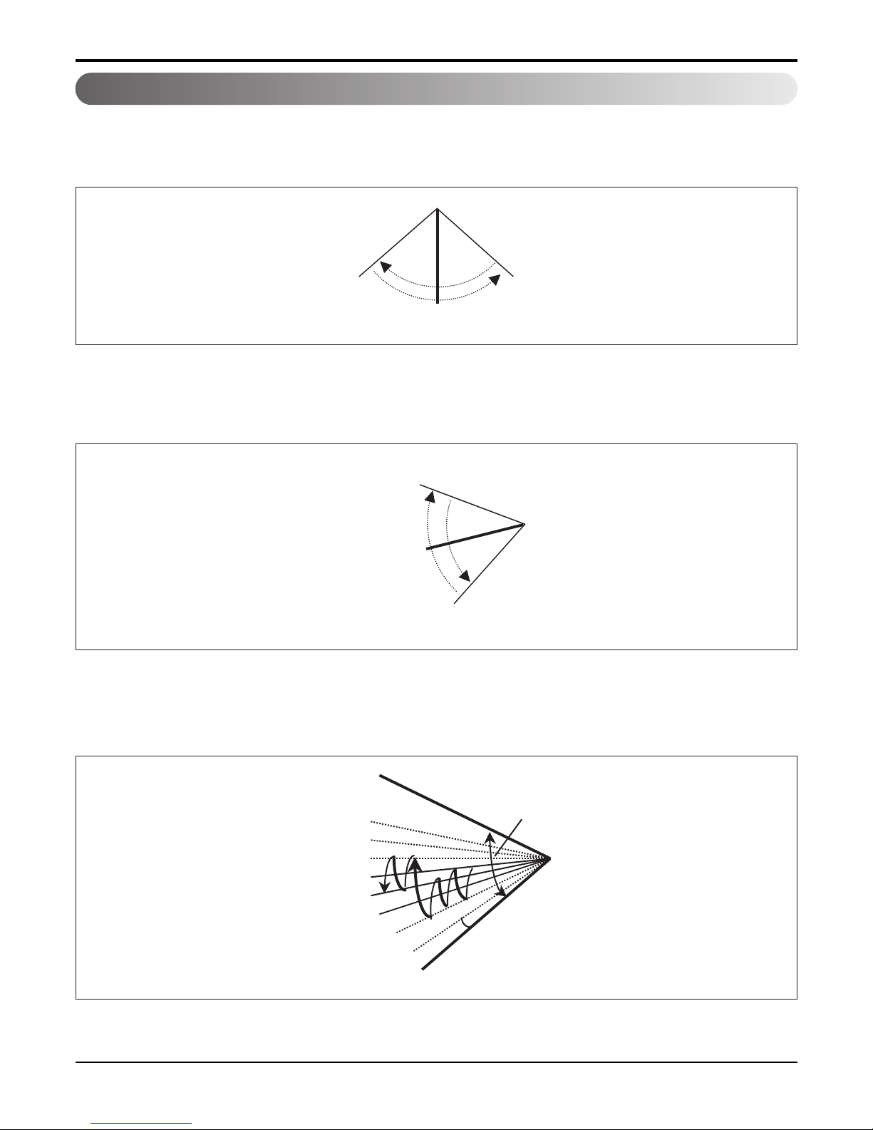
2.1 Auto swing (left & right)
RightLeft
110° ~ 120°
Open
Close
110° ~ 120°
Mode2
Mode3
Mode4
Mode5
Mode6
Mode7
Mode8
Mode9
OPEN
CLOSED
7~8°
110~120°
• By the horizontal airflow direction control key input, the left/right louver automatically operates with the auto swing or it
is fixed to the desired direction.
2.2 Auto swing (up & down)
• By the auto swing key input, the upper/lower vane automatically operates with the auto swing or it is fixed to the
desired direction.
2.3 Chaos swing (up/down)
• By the Chaos swing key input, the upper/lower vane automatically operates with the chaos swing or it is fixed to the
desired direction.
NOTE: Some Models are different by swing width and swing pattern.
- 17 -
Copyright ©2007 LG Electronics. Inc. All right reserved.
Only for training and service purposes
LGE Internal Use Only
Part 2 Functions & Controls
2.4 Air flow step
• Indoor fan motor control have 6 steps.
• Air volume is controlled "SH", "H", "Med", Low" by remote controller.
• "LL" step is selected automatically in Hot start operation.
2.5 Chaos wind (auto wind)
• When "Auto" step selected and then operated, the high, medium, or low speed of the airflow mode is operated for
2~15 sec. randomly by the Chaos Simulation
2.6 Jet Cool Mode Operation
• While in heating mode or Fuzzy operation, the Jet Cool key cannot be input.
When it is input while in the other mode operation (cooling, dehumidification, ventilation), the Jet Cool mode is operated.
• In the Jet Cool mode, the indoor fan is operated at super-high speed for 30 min. at cooling mode operation.
• In the Jet Cool mode operation, the room temperature is controlled to the setting temperature, 18°C.
• When the sleep timer mode is input while in the Jet Cool mode operation, the Jet Cool mode has the priority.
• When the Jet Cool key is input, the upper/lower vanes are reset to those of the initial cooling mode and then operated
in order that the air outflow could reach further.
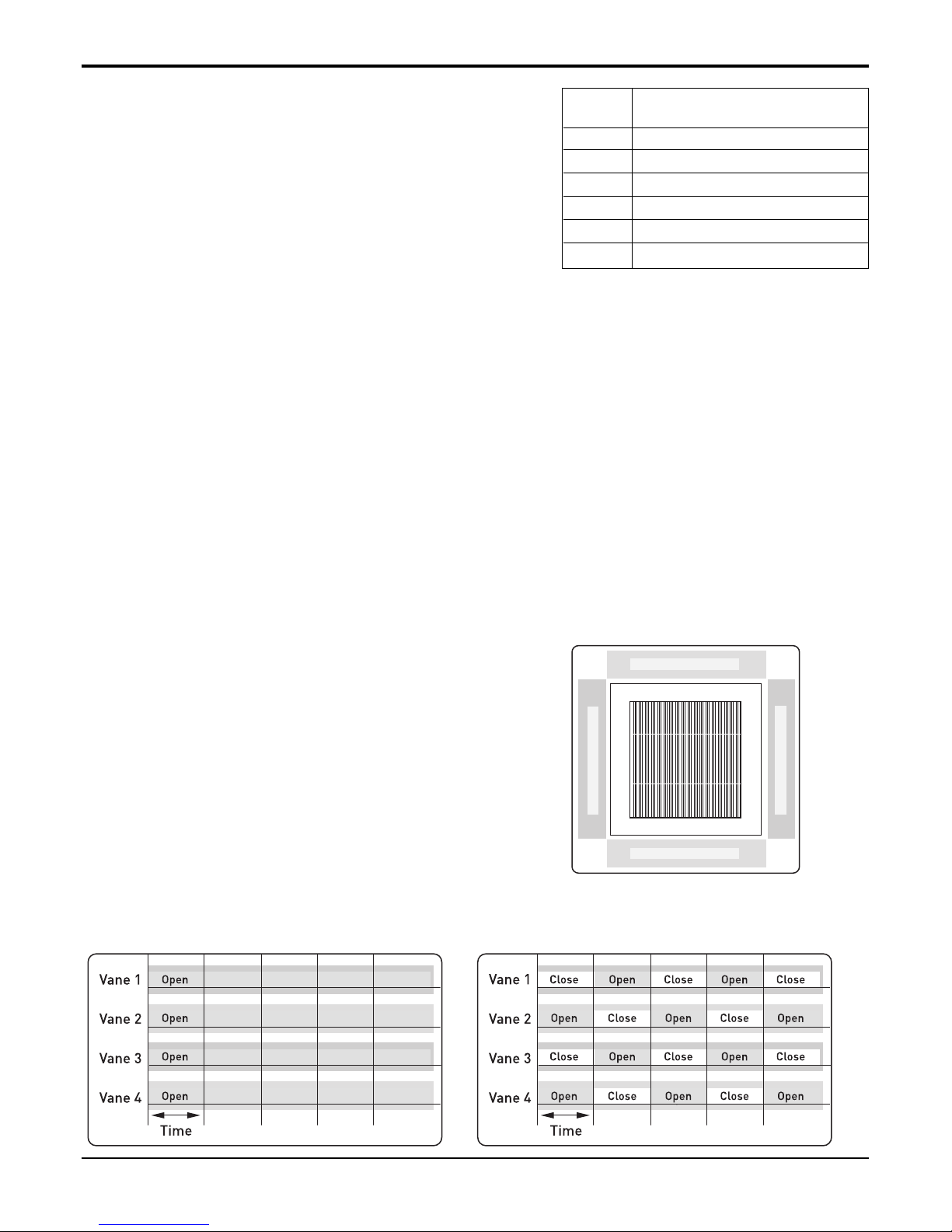
2.7 Swirl wind Swing
• It is the function for comfort cooling/heating operation.
• The diagonal two louvers are opened the more larger
than the other louvers. After one minute, it is opposite.
• Comparison of Air Flow Types
4-Open (conventional) Swirl Swing (New)
LL Very low, In heating mode
L Low
M Med
H High
SH Super high
Auto Chaos wind
Step Discription
Vane 4
Vane 2
Vane 1 Vane 3

- 18 -
Copyright ©2007 LG Electronics. Inc. All right reserved.
Only for training and service purposes
LGE Internal Use Only
Part 2 Functions & Controls
3.1 PLASMA Air Purifying System
The PLASMA Air Purifying System not only removes microscopic contaminants and dust, but also removes house
mites, pollen, and pet fur to help prevent allergic diseases like asthma. This filter that can be used over and over again
by simply washing with water.
3. Air purifying
Ionizer
Photo-Catalyst Coated Mesh
Dust particles
Odour
Dust electrode discharge
Odour molecule
Generating plasma
+
+
+
+
Polluted Air
Purified fresh Air
+4.8KV discharge
+
- 19 -
Copyright ©2007 LG Electronics. Inc. All right reserved.
Only for training and service purposes
LGE Internal Use Only
Part 2 Functions & Controls
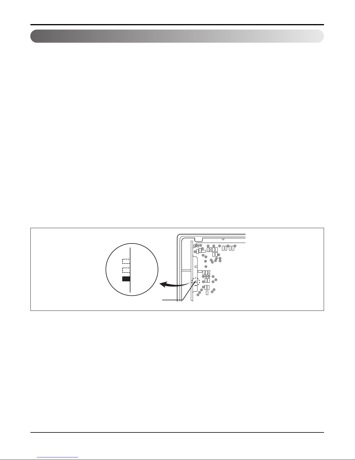
4.1 E.S.P. (External Static Pressure) Setting
4.1.1 Open the rear cover of the wired remote-controller to set the mode.
4.1.2 Select one of three selectable modes as follows.
■ Without Zone System
1. Position V-H, F-H
• This position sets the maximum E.S.P. as a default set.
2. Position V-L
• This position sets the minimum E.S.P. as a default set.
■ With Zone System
1. Position V-H
• Maximum E.S.P. setting & Fan speed is varied according to the state of dampers by micom.
2. Position F-H
• Maximum E.S.P. setting & Fan speed doesn't vary according to the opening & closing of dampers.
3. Position V-L
• Minimum E.S.P setting & Fan speed is varied according to the state of dampers by micom.
* Maximum : 8mmAq
Minimum : 0mmAq
4.1.3 Move the slide switch to set position.
4.1.4 Close the rear cover and check if it works normally.
4. Installation Functions
TH
R14H
SW TH
REMO
MAIN
2TH
OP7
R18H
R17H
OP6
LO
STAND
SW HIGH
HI
R03S
C070
R04S
R02S
R01S
OP3
OP2 OP1
R19H
R11H
R13H R12H
OP5R16H OP4
R15H
CO1H
V-H
V-L
F-H
Slide switch for ceiling height

- 20 -
Copyright ©2007 LG Electronics. Inc. All right reserved.
Only for training and service purposes
LGE Internal Use Only
Part 2 Functions & Controls
4.1.5 How to Set E.S.P?
Procedure of RPM change:
Ex) External Static pressure is 4mmAq for Model 36K.
• To protect the unit, compressor is designed to be off during E.S.P. setting.
Preheat
ZONE
Operation unit Program set
Room Temp
MED
LO
AUTO
JET
Heater
Defrost
Filter
Humidify
Out door
Set no. Time
01 03 05 07 09 11 13 15 17 19 21 23
OPERATION
FAN SPEED
SUB FUNCTION
SET TEMP
HI
AUTO SWING
Time
Preheat
ZONE
Operation unit Program set
Room Temp
MED
LO
AUTO
JET
Heater
Defrost
Filter
Humidify
Out door
Set no. Time
01 03 05 07 09 11 13 15 17 19 21 23
OPERATION
FAN SPEED
SUB FUNCTION
SET TEMP
HI
AUTO SWING
Time
Time
SUB FUNCTION
SET TEMP
OPERATIONAUTO SWING
Preheat
ZONE
Operation unit Program set
Room Temp
MED
LO
AUTO
JET
Heater
Defrost
Filter
Humidify
Out door
Set no. Time
01 03 05 07 09 11 13 15 17 19 21 23
FAN SPEED
HI
Time
SUB FUNCTION
SET TEMP
OPERATIONAUTO SWING
Preheat
ZONE
Operation unit Program set
Room T
MED
LO
AUTO
JET
Heater
Defrost
Filter
Humidify
Out door
Set no. Time
emp
01 03 05 07 09 11 13 15 17 19 21 23
FAN SPEED
HI
2
Timer
1
2
3
5
4
Timer
Push the"On/Off"button.
The unit will start.
Push the "Timer" and "Wind" button simultaneously for more then 3 seconds.
Push the "Up" of "Down" button for E.S.P adjustment.
And, adjust the number which you want.(In this example, the number is "225". Refer to the
table 1 on the next page.)
Shift the fan speed mode by pressing the fan speed button.
And then, Adjust numbers of next steps by repeating the stage 3.
(In this example, the numbers are "237" and "243" respectly)
Push the "Timer" and "Wind" button simultaneously for more than 3 seconds.
Then, Wind Data is memorized by the EEPROM of the main PCB.
Note: The range of selection is from 1~254. Since, the display is two Digit only.
If the range selection is above 100 then the third digit will appear in the screen as shown.
Part 2 Functions & Controls
- 21 -
Copyright ©2007 LG Electronics. Inc. All right reserved.
Only for training and service purposes
LGE Internal Use Only
Static pressure(mmAq)
Setting value
012
Model name
Step(Hi/Med/Lo)
8 CMM 220 215 210
7 CMM 240 235 230
6 CMM 255 250 245
10 CMM 210 85 150
9 CMM 215 190 170
8 CMM 220 200 175
14 CMM 170 150 130
13 CMM 185 165 145
12 CMM 200 180 160
AMNH096BTG0
[MB09AHL NT0]
AMNH126BTG0
[MB12AHL NT0]
AMNH186BTG0
[MB18AHL NT0]
Static pressure(mmAq)
Setting value
01234
Model name
Step(Hi/Med/Lo)
8.5 CMM 75 84 94 104 114
7.5 CMM 69 77 88 99 110
6.5 CMM 62 71 83 95 106
9.5 CMM 82 90 99 109 118
8.5 CMM 75 84 94 104 114
7.5 CMM 69 77 88 99 110
15 CMM 90 97 105 114 122
13.5 CMM 82 90 99 109 119
11.5 CMM 75 84 93 103 114
17 CMM 110 117 125 129 -
15 CMM 100 107 115 121 127
13.5 CMM 90 97 105 114 122
AMNH09GB1A0/1
[MB09AHL N10/1]
AMNH12GB1A0/1
[MB12AHL N10/1]
AMNH18GB2A0/1
[MB18AHL N20/1]
AMNH24GB2A0/1
[MB24AHL N20/1]
E.S.P. setting value (reference)
Static pressure(mmAq) 0 2 4
Model name
Step(Hi/Med/Lo)
Setting value
10.5CMM 225 220 210
AMNH096BPA0
9CMM 245 240 230
8.5CMM 254 253 250
11.5CMM 210 200 100
AMNH126BPA0
10CMM 235 230 220
8.5CMM 254 251 245
[ Notes ]
1. To get the desired Airflow & E.S.P. combination from the table set the matching value from the table. Value other than
that in table will not give the combinations of airflow & E.S.P. which are mentioned in the table.
2. Table data is based at 230V. According to the fluctuation of voltage, air flow rate varies.
- 22 -
Copyright ©2007 LG Electronics. Inc. All right reserved.
Only for training and service purposes
LGE Internal Use Only
Part 2 Functions & Controls
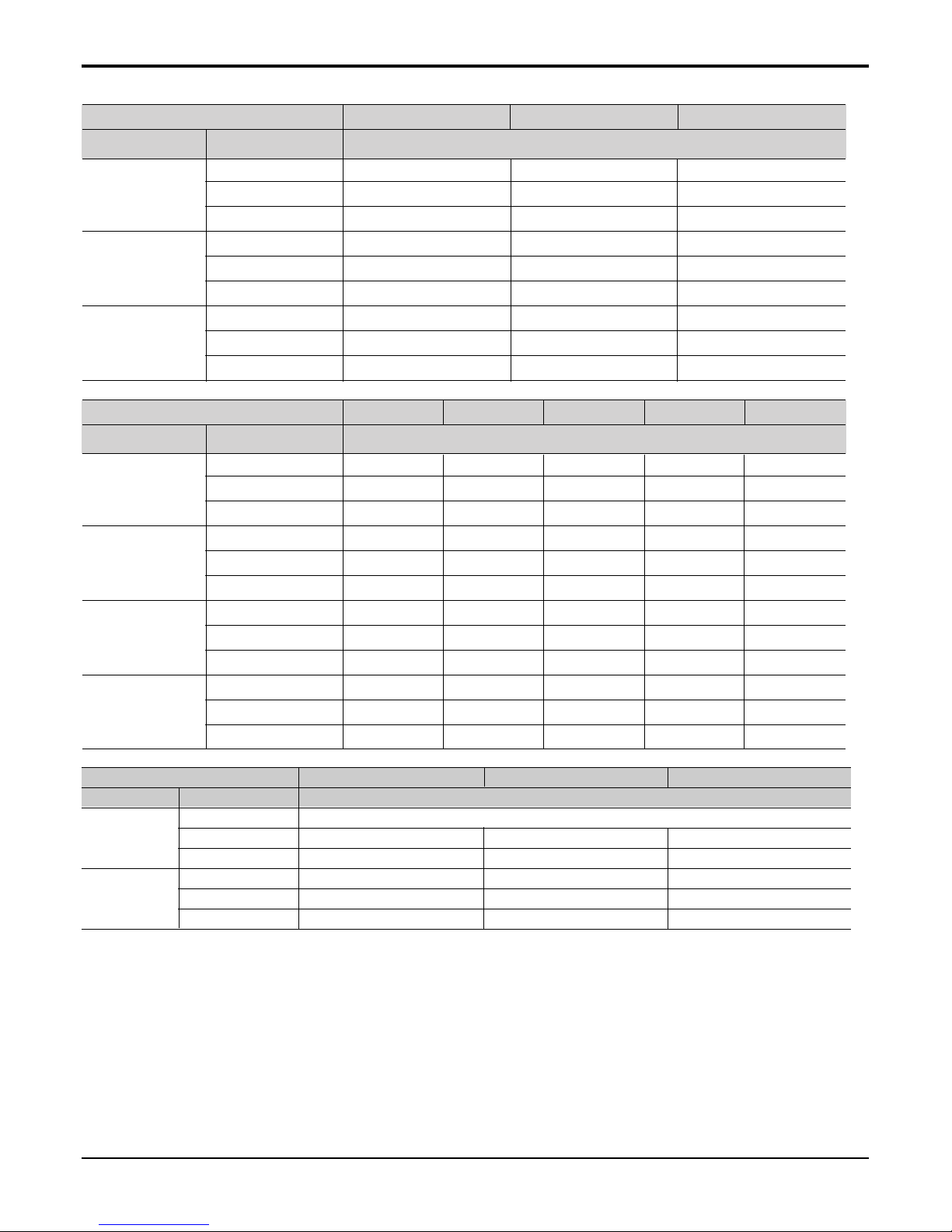
4.2 High Ceiling operation
Function to Control the Air Volume by Ceiling Height Control of the air intensity has been made possible by employing a
height-control algorithm for the interior fan.
According to the height of the installation, it provides variability of indoor fan motor rpm. If the height of installation is low
then you can adjust low rpm of indoor fan motor. On the other hand if the height of the installation is high you can adjust
high rpm of indoor fan motor. Selection of speed can be done by slide switch at the back of the LCD wired remote.
Installation on the
normal-height ceiling
installation on the
higher ceiling
Elevation Choice Conditions of Release
Low
Standard
Hi
- When the elevation is low: lower than 2.4m in height.
- Operate the device at one level lower than the
standard level.
- When the elevation is standard: about 2.7m in
height.
- Operate the device at the standard air flow level.
- When the elevation is high: higher than 3.0m in
height.
- Operate the device at one level higher than the
standard level.

- 23 -
Copyright ©2007 LG Electronics. Inc. All right reserved.
Only for training and service purposes
LGE Internal Use Only
Part 2 Functions & Controls
5.1 Hot start
• When heating is started, the indoor fan is stopped or very slow to prevent the cold air carry out
• When the temp. of heat exchanger reach 30°C(model by model), indoor fan is started.
5.2 Self-diagnosis Function
• The air conditioner installed can self-diagnosed its error status and then transmits the result to the central control.
Therefore, a rapid countermeasure against failure of the air conditioner allows easy management and increases the
usage life of air conditioner.
• Refer to trouble shooting guide.
5.3 Soft dry operation
• When the dehumidification operation input by the remote control is received, the intake air temperature is detected and
the setting temp is automatically set according to the intake air temperature.
• While compressor off, the indoor fan repeats low airflow speed and stop.
• While the intake air temp is between compressor on temp. and compressor off temp., 10-min dehumidification opera-
tion and 4-min compressor off repeat.
Compressor ON Temp. ➔ Setting Temp+0.5°C
Compressor OFF Temp. ➔ Setting Temp-0.5°C
• In 10-min dehumidification operation, the indoor fan operates with the low airflow speed.
5. Reliability
Intake air Temp. Setting Temp.
26°C ≤ intake air temp. 25°C
24°C ≤ intake air temp.< 26°C intake air temp. -1°C
22°C ≤ intake air temp. < 24°C intake air temp. -0.5°C
18°C ≤ intake air temp. < 22°C intake air temp.
intake air temp. < 18°C18°C
- 24 -
Copyright ©2007 LG Electronics. Inc. All right reserved.
Only for training and service purposes
LGE Internal Use Only
Part 2 Functions & Controls
6. Convenience Functions & Controls
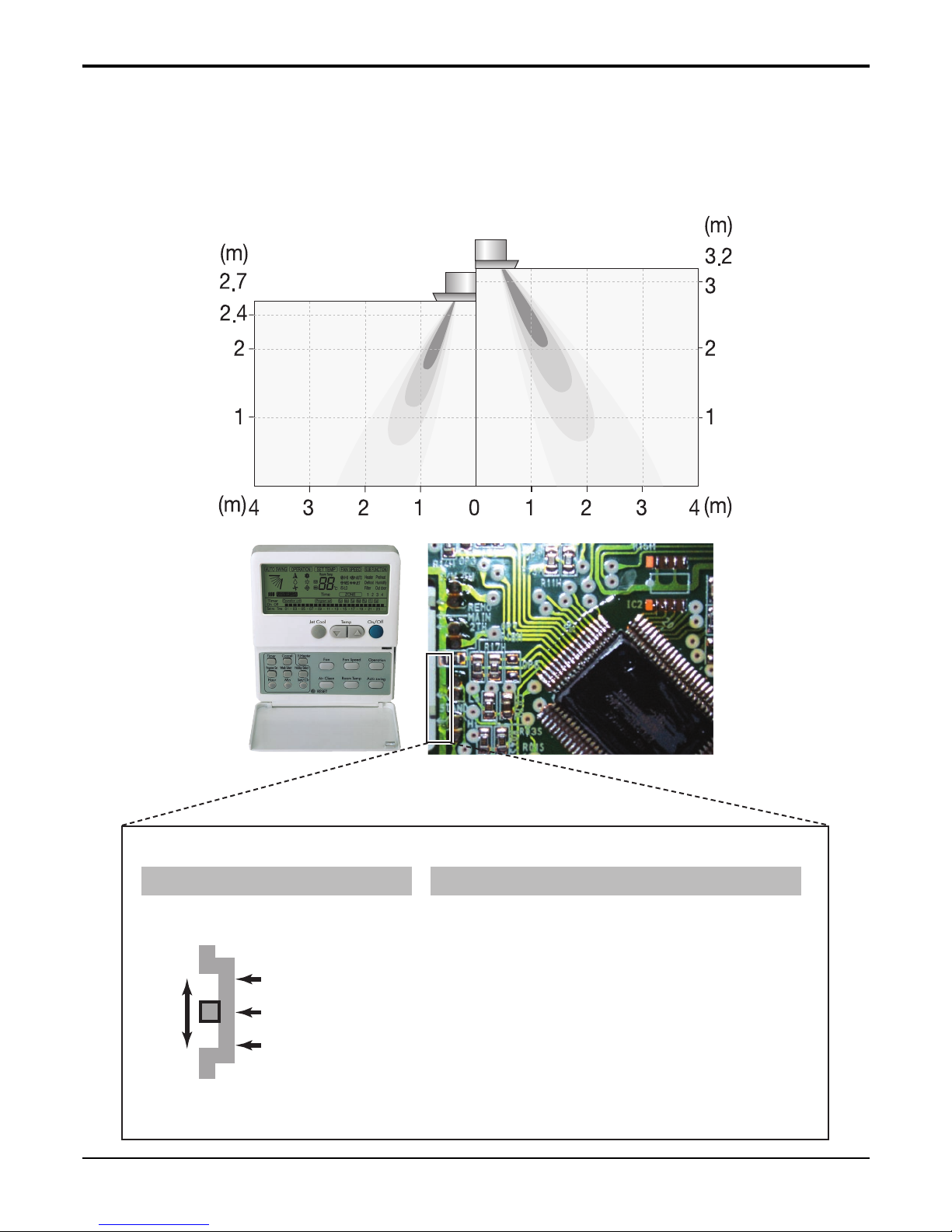
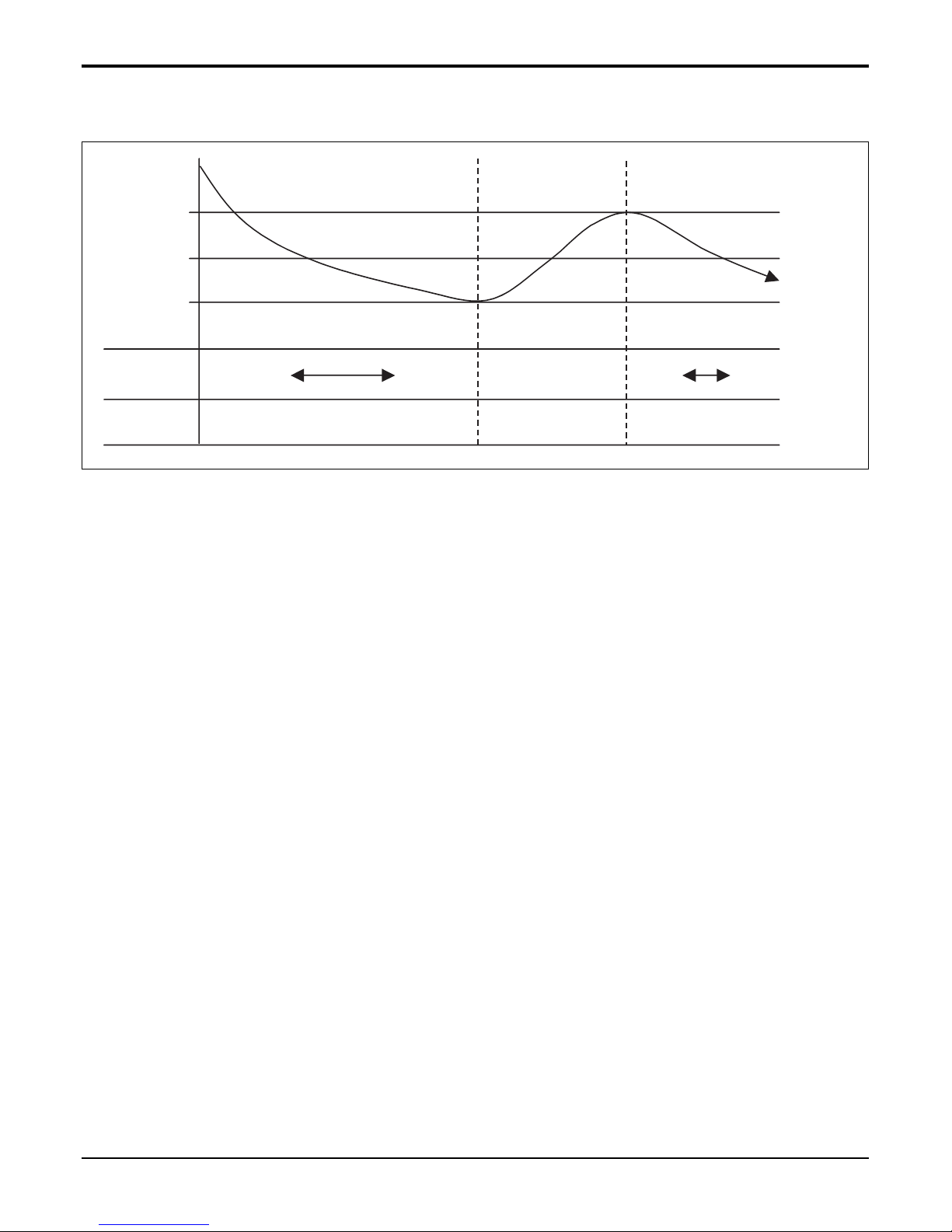
6.1 Auto changeover operation
• The air conditioner changes the operation mode automatically to keep indoor temperature.
• When room temperature vary over ±2°C with respect to setting temperature, air conditioner keeps the room tempera-
ture in ±2°C with respect to setting temperature by auto change mode.
SET Temp.
+0.5°C
-0.5°C
-2°C
+4°C
+2°C
Cooling
operation
Heating operation Cooling
operation
Cooling thermo off
Heating thermo off
Switching point
Switching point
- 25 -
Copyright ©2007 LG Electronics. Inc. All right reserved.
Only for training and service purposes
LGE Internal Use Only
Part 2 Functions & Controls
■ Cooling & heating Opeattions
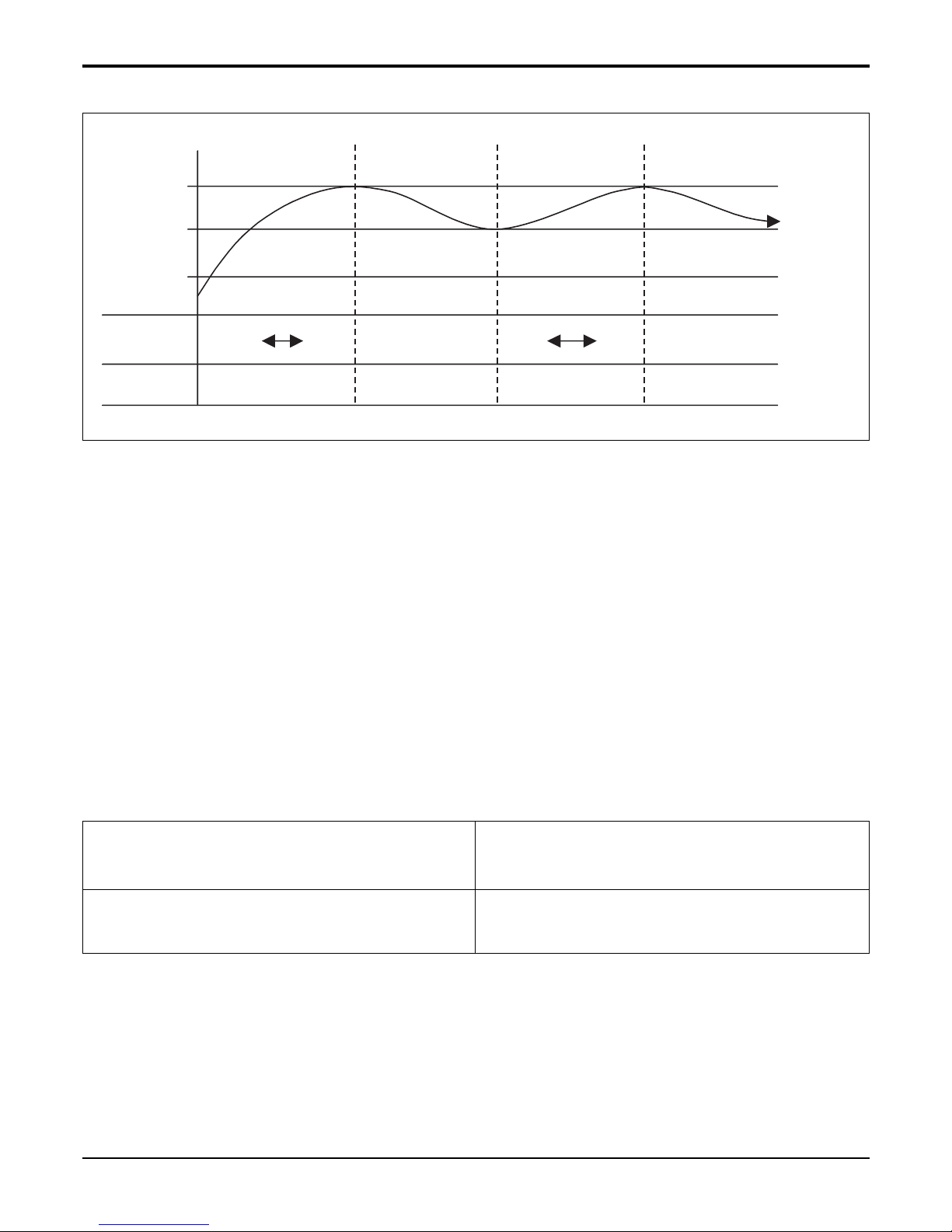
6.1.1 Cooling Mode
Setting
Temp.
-0.5°C.
+0.5°C.
Comp. OFF
Comp. ON Comp. OFF Comp. ON
INV. Comp.
Frequency
Constant
Comp.
Low
High Low
Thermo.
ON
Thermo
OFF
High
• Operating frequency of compressor depends on the load condition, like the difference between the room temp. and
the set temp., frequency restrictions.
• If the compressor operates at some frequency, the operating frequency of compressor cannot be changed within 30
seconds. ( not emergency conditions)
• Compressor turned off when
- intake air temperature is in between ±0.5°C of the setting temp. limit for three minutes continuously.
- intake air temperature reaches below 1.0°C of the temperature of setting temp..
• Compressors two minutes time delay.
- After compressor off, the compressor can restart minimum 2 minutes later.
- 26 -
Copyright ©2007 LG Electronics. Inc. All right reserved.
Only for training and service purposes
LGE Internal Use Only
Part 2 Functions & Controls
6.1.2 Heating Mode
+2°C.
+4°C.
Comp. OFF
Comp. ON Comp. OFF Comp. ON Comp. OFF
INV. Comp.
Frequency
Constant
Comp.
Low
High LowHigh Comp. OFF
Thermo
ON
Thermo
OFF
Setting
Temp.
• Operating frequency of compressor depend on the load condition, The difference between the room temp. and set
temp., frequency restrictions.
• If compressor operates at some frequency, the operating frequency of compressor cannot be changed within 30 sec-
onds.
• Condition of compressor turned off
- When intake air temperature reaches +4°C above the setting temperature.
• Condition of compressor turned on
- When intake air temperature reaches +2°C above the setting temperature.
* Condition of indoor fan turned off
- While in compressor on : indoor pipe temp. < 20°C
- While in compressor off : indoor pipe temp. < 30°C
• While in defrost control, between the indoor and outdoor fans are turned off.
• Compressor 2minutes delay
- After compressor off, the compressor can restart minimum 2 minutes later.
CST/Duct/CVT type indoor unit matched with
Universal Outdoor unit
CST/ Duct/CVT type indoor unit
matched with Single Outdoor unit/Multi
Outdoor unit/Multi V Outdoor unit
Thermo ON : +2 °C above setting temp.
Thermo OFF : +4 °C above setting temp.
Thermo ON : Setting temp.
Thermo OFF : +3 °C above setting temp.
NOTE: Some Models are different by temperature of thermo ON/OFF.
- 27 -
Copyright ©2007 LG Electronics. Inc. All right reserved.
Only for training and service purposes
LGE Internal Use Only
Part 2 Functions & Controls
* Some Models are different with temperature of indoor fan ON/OFF
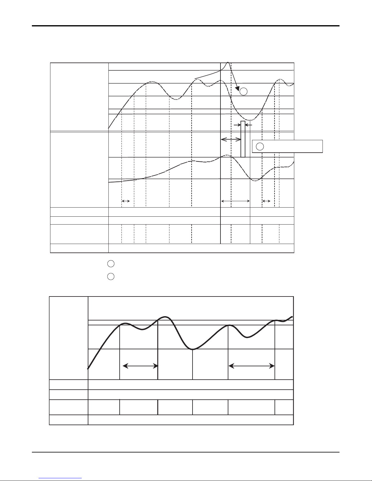
■ Heating Mode Operation Details
The unit will operate according to the setting by the remote controller and the operation diagram is shown as following.
COMP
Outdoor fan
Indoor fan
4way valve
Setting Temperature
(Thermo ON)
Setting Temperature
+3°C
(Thermo OFF)
Indoor unit
Heat-Exchanger
temperature
1min
Minimum
3min
1min
3min
Setting
fan
speed
Setting
fan
speed
Setting
fan
speed
ON
ON
ON
ON
Low
LowLowLow
Low
Lo
OffOffOff
ON
OFF
OFF
Low fan during 10sec
A
A
B
B
Intake Air Temperature
• Compressor-off interval : - While the indoor Heat-Exchanger temperature is higher than 40°C, fan operates
at low speed, when it becomes lower than 40°C fan stops.
- For eluminating latent heat-loss, fan operates at low speed for 10 seconds periodically.
40°C
33°C
30°C
27°C
20°C
ON
ON
Off Off
Low Low
1min1min
20°C
27°C
33°C
Indoor unit
Heat-Exchanger
temperature
Setting fan
speed
Setting fan
speed
Compressor
Outdoor fan
Indoor fan
4way Valve
ON
- 28 -
Copyright ©2007 LG Electronics. Inc. All right reserved.
Only for training and service purposes
LGE Internal Use Only
Part 2 Functions & Controls
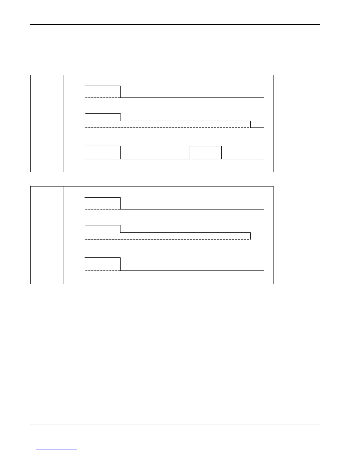
6.2 Auto cleaning operation
• Function used to perform Self Cleaning to prevent the Unit from Fungus and bad odor.
• Used after the Cooling Operation before turning the unit off, clean the Evaporator and keep it dry for the next opera-
tion.
• The function is easy to operate as it is accessed through the Remote controller.
Unit
Operation
13~14 minutes 1 minute 2~3 minutes
ON
OFF
Comp.
Indoor
Fan
ON
OFF
ON
OFF
Setting step
OFFL Low
Setting step
Unit
Operation
ON
OFF
Comp.
Indoor
Fan
ON
OFF
ON
OFF
Setting step
OFFL Low
Setting step
(Heat Pump)
(Cooling Only)

- 29 -
Copyright ©2007 LG Electronics. Inc. All right reserved.
Only for training and service purposes
LGE Internal Use Only
Part 2 Functions & Controls
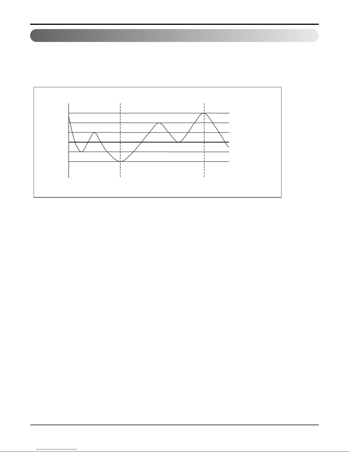
6.3 Auto Operation (Fuzzy Operation)
• When any of operation mode is not selected like the moment of the power on or when 3 hrs has passed since the
operation off, the operation mode is selected.
• When determining the operation mode, the compressor, the outdoor fan, and the 4 way valve are off and only the
indoor fan is operated for 15 seconds. Then an operation mode is selected according to the intake air temp at that
moment as follows.
24°C ≤ Inatake Air Temp ➔ Fuzzy Operation for Cooling
21°C ≤ Inatake Air Temp < 24°C ➔ Fuzzy Operation for Dehumidification
Inatake Air Temp < 21°C ➔ Fuzzy Operation for Heating
• If any of the operation modes among cooling / dehumidification / heating mode operations is carried out for 10 sec or
longer before Fuzzy operation, the mode before Fuzzy operation is operated.
6.3.1 Fuzzy Operation for Cooling
• According to the setting temperature selected by Fuzzy rule, when the intake air temp is 0.5°C or more below the setting temp, the compressor is turned off. When 0.5°C or more above the setting temp, the compressor is turned on.
Compressor ON Temp ➔ Setting Temp + 0.5°C
Compressor OFF Temp ➔ Setting Temp + 0.5°C
• At the beginning of Fuzzy mode operation, the setting temperature is automatically selected according to the intake air
temp at that time.
26°C≤ Intake Air Temp ➔ 25°C
24°C≤ Intake Air Temp<26°C ➔ Intake Air Temp + 1°C
22°C≤ Intake Air Temp<24°C ➔ Intake Air Temp + 0.5°C
18°C≤ Intake Air Temp<22°C ➔ Intake Air Temp
Intake Air Temp<18°C ➔ 18°C
• When the Fuzzy key (Temperature Control key) is input after the initial setting temperature is selected, the Fuzzy key
value and the intake air temperature at that time are compared to select the setting temperature automatically according to the Fuzzy rule.
• While in Fuzzy operation, the airflow speed of the indoor fan is automatically selected according to the temperature.
6.3.2 Fuzzy Operation for Dehumidification
• According to the setting temperature selected by Fuzzy rule, when the intake air temp is 0.5°C or more below the setting temp, the compressor is turned off. When 0.5°C or more above the setting temp, the compressor is turned on.
Compressor ON Temp ➔ Setting Temp + 0.5°C
Compressor OFF Temp ➔ Setting Temp+0.5°C
• At the beginning of Fuzzy mode operation, the setting temperature is automatically selected according to the intake air
temp at that time.
26°C ≤ Intake Air Temp ➔ 25°C
24°C ≤ Intake Air Temp<26°C ➔ Intake Air Temp+1°C
22°C ≤ Intake Air Temp<24°C ➔ Intake Air Temp+0.5°C
18°C ≤ Intake Air Temp<22°C ➔ Intake Air Temp
Intake Air Temp<18°C ➔ 18°C
• When the Fuzzy key (Temperature Control key) is input after the initial setting temperature is selected, the Fuzzy key
value and the intake air temperature at that time are compared to select the setting temperature automatically according to the Fuzzy rule.
• While in Fuzzy operation, the airflow speed of the indoor fan repeats the low airflow speed or pause as in dehumidification operation.
 Loading...