

Page 1
- 29 -
NOTES : Resistance values are indicted in ohms unless otherwise specified (K=1,000, M=1,000,000).
Capacitance values are shown in microfarads unless otherwise (P=MICRO-MICRO FARADS).
Schematic diagram for this model are subject to change for improvement without prior notice.
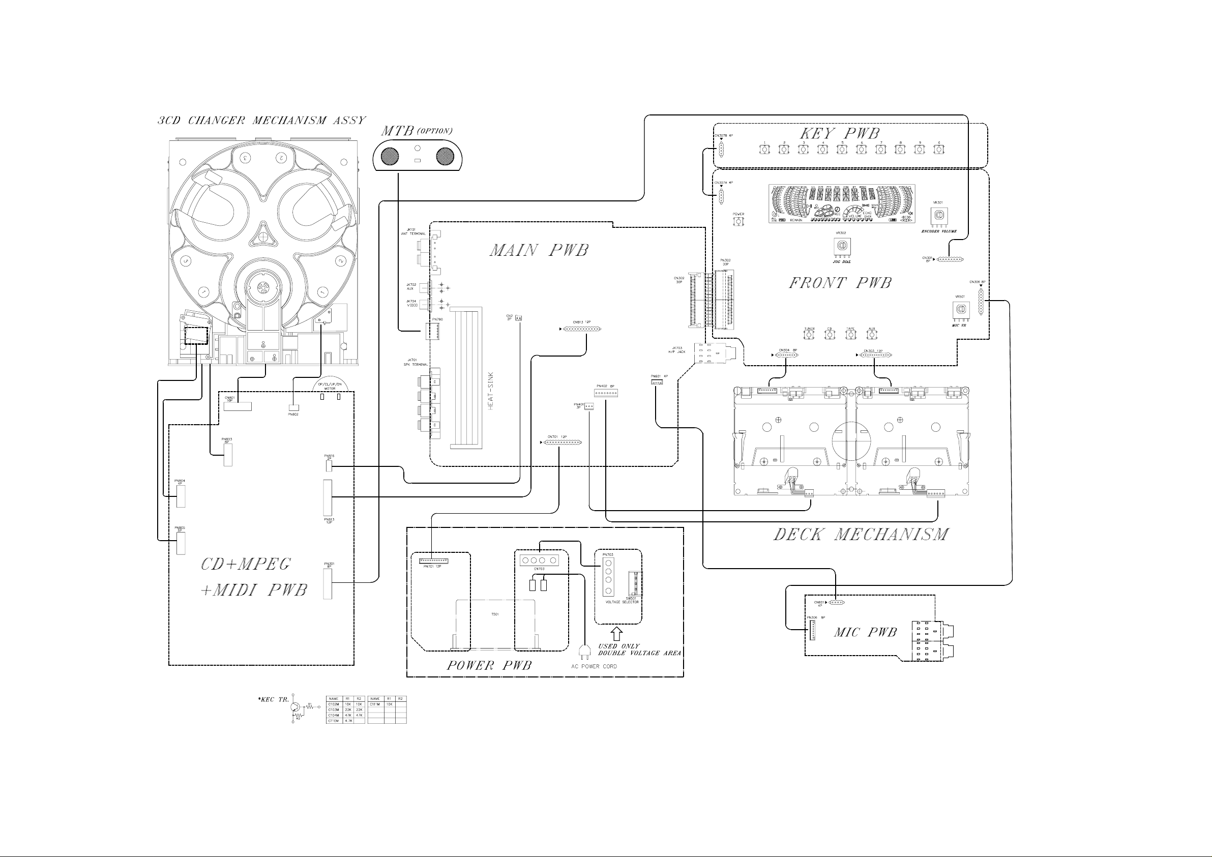
WIRING DIAGRAM
LG FFH-2000AX
Page 2
- 22 -
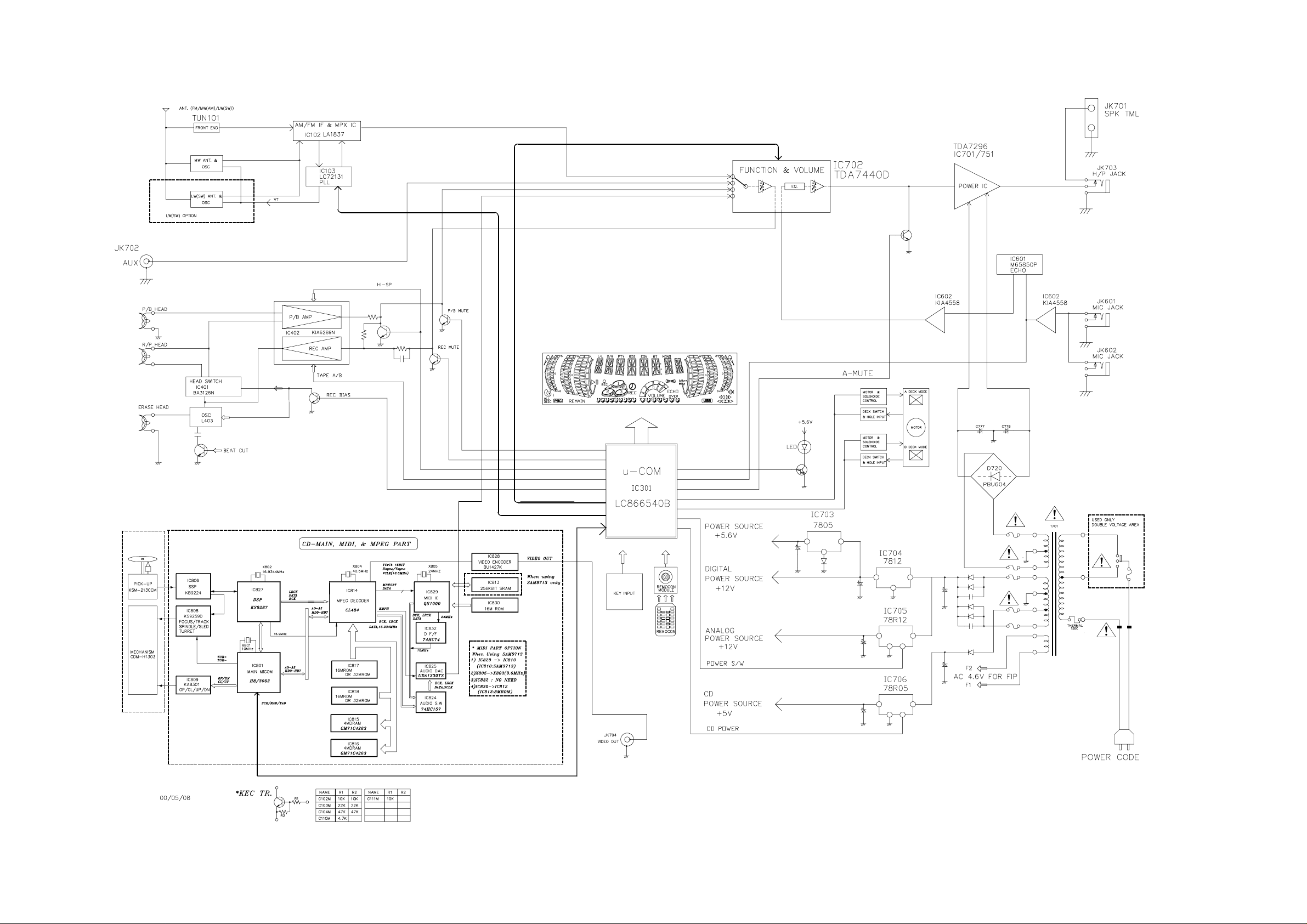
BLOCK DIAGRAM
Page 3
- 25 -
NOTES : Resistance values are indicted in ohms unless otherwise specified (K=1,000, M=1,000,000).
Capacitance values are shown in microfarads unless otherwise (P=MICRO-MICRO FARADS).
Schematic diagram for this model are subject to change for improvement without prior notice.
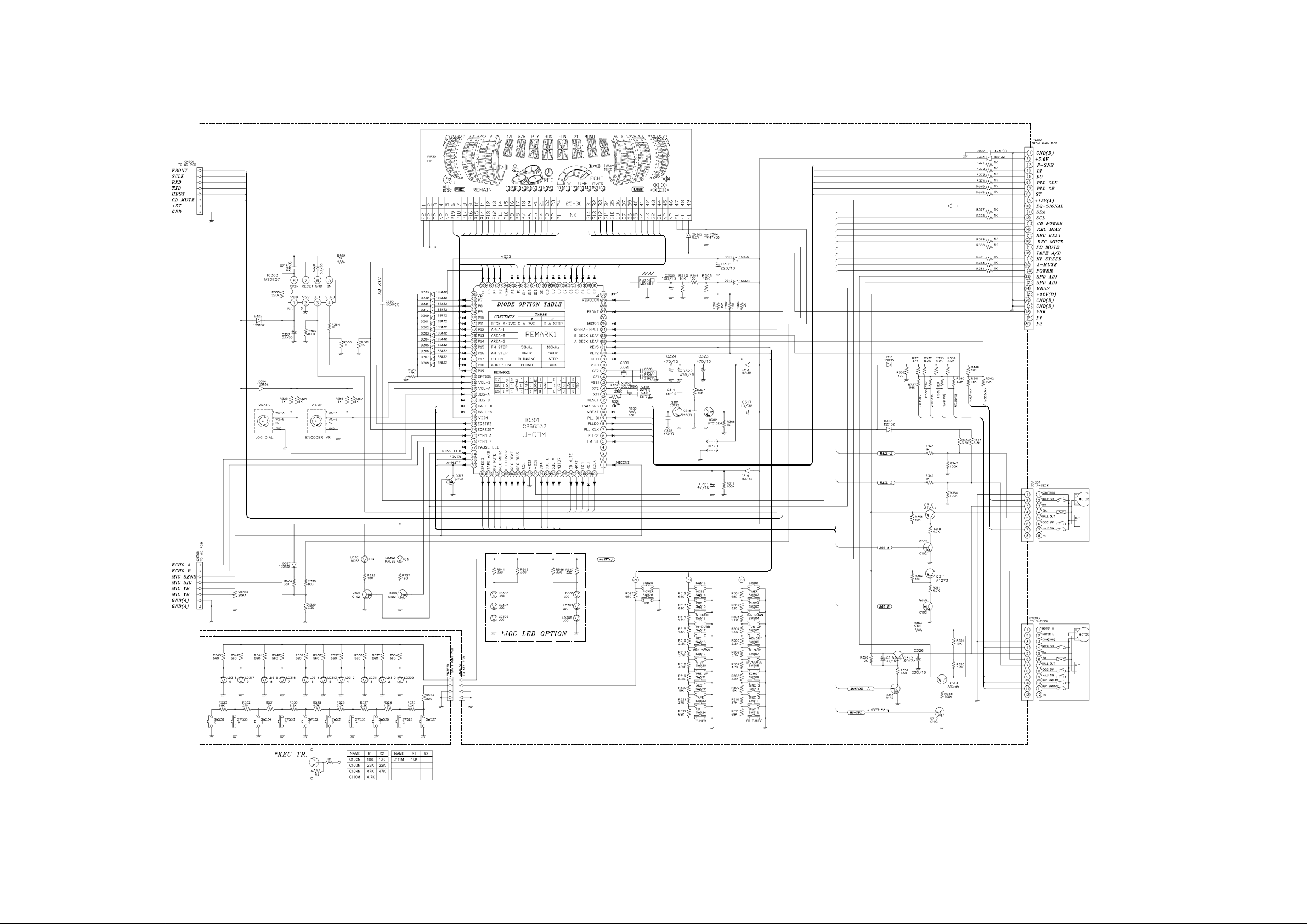
• FRONT
Page 4

- 23 -
SCHEMATIC DIAGRAMS
• MAIN
NOTES : 1. Resistance values are indicted in ohms unless otherwise specified (K=1,000, M=1,000,000).
2. Capacitance values are shown in microfarads unless otherwise (P=MICRO-MICRO FARADS).
3. Schematic diagram for this model are subject to change for improvement without prior notice.
Page 5

- 24 -
• TUNER & DECK
NOTES : Resistance values are indicted in ohms unless otherwise specified (K=1,000, M=1,000,000).
Capacitance values are shown in microfarads unless otherwise (P=MICRO-MICRO FARADS).
Schematic diagram for this model are subject to change for improvement without prior notice.
Page 6

- 27 -
• MIDI
Page 7

- 28 -
• CD/MPEG
Page 8

- 8 -
ADJUSTMENTS
This set has been aligned at the factory and normally will not require further adjustment. As a result, it is not
recommended that any attempt is made to modificate any circuit. If any parts are replaced or if anyone tampers
with the adjustment, realignment may be necessary.
IMPORTANT
1. Check Power-source voltage.
2. Set the function switch to band being aligned.
3. Turn volume control to minimum unless otherwise noted.
4. Connect low side of signal source and output indicator to chassis ground unless otherwise specified.
5. Keep the signal input as low as possible to avoid AGC and AC action.
TAPE DECK ADJUSTMENT
1. AZIMUTH ADJUSTMENT
Figure 2. Azimuth Adjustment Connection Diagram
CH1 CH2
Speaker Out
Playback Mode
Head
Test Tape
MTT-114
L ch
R ch
GND
Dual-trace
synchroscope
Electronic
Voltmeter
L out
R out
Unit
Deck Mode Test Tape Test Point Adjustment Adjust for
A Deck Playback MTT-114 Speaker Out Azimuth Screw Maximum
B Deck Playback MTT-114 Speaker Out Azimuth Screw Maximum
Page 9

- 9 -
2. MOTOR SPEED ADJUSTMENT
Figure 3. Motor Speed Adjustment Connection Diagram
Deck Mode Test Tape Test Point Adjustment Adjust for Remark
Normal Speed MTT-111 Speaker Out VR401 3kHz ± 1% A Deck
HI-Speed MTT-111 Speaker Out more than 5.4kHz HI-Speed Dubbing Mode
3. RECORD BIAS ADJUSTMENT
Head
Unit
PN402
GND
Record/Playback
head
Test Tape
MTT-5511
Record/Playback
and Pause Mode
Frequency Counter
Deck Mode Test Tape Test Point Adjustment Adjust for
Rec/Pause MTT-5511 PN402 L403 90kHz±5kHz
Figure 4. Record Bias Adjustment Connection Diagram
Head
Test Tape
MTT-111
Record/Playback
head
Playback Mode
L out
Unit
R out
Speaker Out
GND
Frequency Counter
 Loading...