

LG FE-2005VE Owner's Manual

NEW
KARAOKE
MUSIC
SYSTEM
OWNER'S
MANUAL
MODELS
:
FFH-2005AX
FE-2005VE
Please
read
this
manual
carefully
before
operating
your
unit.
Retain
it
for
future
reference.
Designs
and
specifications
are
subject
to
change
without
notice
for
improvement.
P/N:3828R-A012A
English
Russian
Kazakh

1

2
IMPORTANT
SAFETY
INSTRUCTIONS
FOR
CUSTOMERS
IN
THE
UNITED
STATES
?
Read
instructions-All
the
safety
and
operating
instructions
should
be
read
before
the
product
is
operated.
?
Retain
instructions-The
safety
and
operating
instructions
should
be
retained
for
future
reference.
?
Heed
Warnings
-
All
warnings
on
the
product
and
in
the
operatiog
instructions
should
be
followed.
?
Follow
instructions-All
operating
and
use
instructions
should
be
followed.
?
Cleaning-Unplug
this
product
from
the
wall
outlet
before
cleaning.
Do
not
use
liquid
cleaners
or
aerosol
cleaners.
Use
a
damp
cloth
for
cleaning.
?
Attachments
-
Do
not
use
attachments
not
recommended
by
the
product
manufacturer
as
they
may
cause
hazards.
?
Water
and
Moisture-Do
not
use
this
product
near
water-for
example,
near
a
bath
tub,
wash
bowl,
kitchen
sink,
or
laundry
tub;
in
a
wet
basement;
or
near a
swimming
pool;
and
the
like.
?
Accessories
-
Do
not
place
this
product
on
an
unstable
cart,
stand,
tripod,
bracket,
or
table.
The
product
may
fall,
causing
serious
injury
to
a
child
or
adult,
and
serious
damage
to
the
product.
Use
only
with
a
stand,
tripod,
bracket,
or
table
recommended
by
the
manufactur
or
sold
with
the
product.
Any
mounting
of
the
product
should
follow
the
manufacturer
's
instructions
and
should
use
a
mounting
accessory
recommended
by
the
manufacturer.
?
A
product
and
cart
combination should
be
moved
with
care.
Quick
stops,
excessive
force,
and
uneven
surfaces
may
cause
the
product
and
cart
combination
to
overturn.
?
Ventilation-Slots
and
openings
in
the
cabinet
are
provided
for
ventilation
and
to
ensure
reliable
operation
of
the
product
and
to
protect
it
from
overheating,
and
these
openings
must
not
be
blocked
or
covered.
The
openings
should
never
be
blocked
by
placing
the
product
on
a
bed,
sofa,
rug,
or
other
similar
surface.
This
product
should
not
be
placed
inabuilt-in
installation
such
as a
bookcase
or
rack
unless
proper
ventilation
is
provided
or
the
manufacturer's
instructions
have
been
followed.
?
Power
Sources-This
product
should
be
operated
only
from
the
type
of
power
source
indicated
on
the
marking
label.
If
you
are
not
sure
of
the
type
of
power
supply
to
your
home,
consult
your
product
dealerorlocal
power
company.
For
products
intended
to
operate
from
battery
power,
or
other
sources,
refertothe
operating
instructions.
?
Power-Cord
Protection-Power
supply
cords
should
be
routedsothat
they
are
not
likely
to
be
walked
on
or
pinched
by
items
placed
upon
or
against
them,
paying
particular
attentiontocords
at
plugs,
convenience
receptacles,
and
the
point
where
they
exit
from
the
product.
?
Protective
Attachment
Plug
-
The
product
is
equipped
withanattachment
plug
having
overload
protection.
This
is
a
safety
feature.
See
Instruction
Manual
for
replacementorresttingorprotective
device.
If
replacement
of
the
plugisrequired,
be
sure
the
service
technician
has
used
a
replacement
play
specified
by
the
manufacturer
that
has
the
same
overload
protection
as
the
original
plug.
?
Lightning
-
For
added
protection
for this
product
duringalightning
storm,
or
whenitis
left
unattended
and
unused
for
long
periods
of
time,
unplug
it
from
the
wall
outlet
and
disconnect
the
antenna
or
cable
system.
This
will
prevent
damage
to
the
product
due
to
lightning
and
power-
line
surges.
CAUTION:
?
Read
allofthese
instructions.
?
Save
these
instructions
for
later
use.
?
Follow
all
warnings
and
instructions
maked
on
the
audio
equipment.
3
?
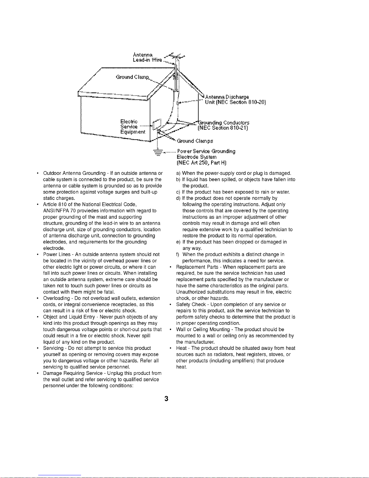
Outdoor
Antenna
Grounding
-
Ifanoutside
antenna
or
cable
system
is
connected
to
the
product,
be
sure
the
antenna
or
cable
system
is
grounded
so as
to
provide
some
protection
against
voltage
surges
and
built-up
static
charges.
?
Article
810
of
the
National
Electrical
Code,
ANSI/NFPA
70
proviedes
information
with
regard
to
proper
grounding
of
the
mast
and
supporting
structure,
grounding
of
the
lead-in
wire
toanantenna
discharge
unit,
size
of
grounding
conductors,
location
of
antenna
discharge
unit,
connection
to
grounding
electrodes,
and
requirements
for
the
grounding
electrode.
?
Power
Lines-An
outside
antenna
system
should
not
be
locatedinthe
vicinity
of
overhead
power
lines
or
other
electric
light
or
power
circuits,
or
where
it
can
fall
into
such
power
linesorcircuits.
When
installing
an
outside
antenna
system,
extreme
care
should
be
taken
not
to
touch
such
power
linesorcircuits
as
contact
with
them
might
be
fatal.
?
Overloading
-
Do
not
overload
wall
outlets,
extension
cords,
or
integral
convenience
receptacles,
as
this
can
result
inariskoffireorelectric
shock.
?
Object
and
Liquid
Entry
-
Never
push
objects
of
any
kind
into this
product
through
openingsasthey
may
touch
dangerous
voltage
points
or
short-out
parts
that
could
result
inafireorelectric
shock.
Never
spill
liquid
of
any
kindonthe
product.
?
Servicing
-
Do
not
attempt
to
service
this
product
yourselfasopeningorremoving
covers
may
expose
you
to
dangerous
voltage
or
other
hazards.
Refer
all
servicingtoqualified
service
personnel.
?
Damage
Requiring
Service
-
Unplug
this
product
from
the
wall
outlet
and
refer
servicingtoqualified
service
personnel
under
the
following
conditions:
a)
When
the
power-supply
cord
or
plugisdamaged.
b)Ifliquid
has
been
spilled,orobjects
have
fallen
into
the
product.
c)
If
the
product
has
been
exposed
to
rain
or
water.
d)
If
the
product
does
not
operate
normally
by
following
the
operating
instructions.
Adjust
only
those
controls
that
are
covered
by
the
operating
instructions
as
an
improper
adjustment
of
other
controls
may
result
in
damage
and
will
often
require
extensive
work
byaqualified
technician
to
restore
the
product
to
its
normal
operation.
e)
If
the
product
has
been
droppedordamaged
in
any
way.
f)
When
the
product
exhibitsadistinct
change
in
performance,
this
indicatesaneed
for
service.
?
Replacement
Parts-When
replacement
parts
are
required,
be
sure
the
service
technician
has
used
replacement
parts
specified
by
the
manufacturer
or
have
the
same
characteristics
as
the
original
parts.
Unauthorized
substitutions
may
result
in
fire,
electric
shock,
or
other
hazards.
?
Safety
Check
-
Upon
completion
of
any
service
or
repairs
to
this
product,
ask
the
service
technician
to
perform
safety
checkstodetermine
that
the
product
is
in
proper
operating
condition.
?
Wall
or
Ceiling
Mounting
-
The
product
should
be
mounted
to
a
wall
or
ceiling
only
as
recommended
by
the
manufacturer.
?
Heat-The
product
should
be
situated
away
from
heat
sources
such
as
radiators,
heat
registers,
stoves,
or
other
products
(including
amplifiers)
that
produce
heat.

4
OPERATING
ELEMENTS
FRONT
VIEW
1.
TUNING
DOWN/UP
buttons(TUNER)
REWIND
/
FAST
FORWARD
buttons(TAPE)
SEARCH
buttons(CD/VCD)
/
TEMPO
+/-
buttons(KARAOKE)
2.
RECORD
/
RECORD
PAUSE
buttons
3.
TIMER
button
4.
CLOCK
button
5.
REMOTE
SENSOR
6.
MDSS
indicator
7.
MDSS
button
8.
POWER
button
9.
DEMONSTRATION,
PBC
ON/OFF,
PLAY
MODE
button
10.
UBB
(Ultra
Bass
Booster)
/
Hi-TONE
button
11.
NORMAL
DUBBING
/CDSYNCHRO
RECORDING
button
12.
HEADPHONE
socket
(PHONES)
13.
HI-SPEED
DUBBING
/
RETURN
/
CANCEL
button
14.
TAPE
DECK
1
EJECT
position
(
PUSH
/
EJECT)
15.
FUNCTION
SELECT
buttons
(TUNER
BAND,
KARAOKE/VCD,
TAPE
1/2,
AUX)
16.
PRESET
DOWN(TUNER)
/
BACKWARD
PLAY
(TAPE:OPTION)
/
RETURN
(VCD,
KARAOKE)
button
(PRESET
DOWN
/
)
17.
TAPE
STOP,
CD
STOP/CLEAR
button
(/CLEAR)
18.
PRESET
UP(TUNER)
/
FORWARD
PLAY
(TAPE)
/
CD
PLAY/SELECT
button
(PRESET
UP
/ /
SELECT)
19.
JOG
DIAL
?
PRESET
DOWN/UP
(TUNER)
?
ADJUST
DOWN/UP
(CLOCK/TIMER)
?
SKIP
DOWN/UP
(CD)
?
PREVIOUS
/
NEXT,
KEY
CONTROL
(VCD,KARAOKE)
20.
TAPE
DECK
2
EJECT
POSITION
(
PUSH
/
EJECT)
21.
MODE
/
RIF
(TUNER)/CD
PAUSE
/
SET(CLOCK
/
TIMER)
/
COUNTER
RESET
(TAPE)
button
(MODE
/
RIF/CDII/
SET/COUNTER
RESET)
22.
MIC
Sockets
23.
DISC
DIRECT
PLAY
buttons
(DISC1,
DISC2,
DISC3)
24.
ECHO
Select
button
25.
CD
OPEN/CLOSE
button
26.
MIC
Volume
27.
CD
PAUSE/SET
indicator
28.
VOLUME
knob
29.
DISC
SKIP
button
30.
MEMORY
/
PROGRAM
button
31.
CD
DOOR
32.
NUMERIC
buttons(1-0)
BACK
VIEW
33.
ANTENNA
(AERIAL)
terminal
34.
AUXILIARY
/
PHONO
(OPTIONAL)
INPUT
SOCKET
35.
VIDEO
OUTPUT SOCKET
36.
SPEAKER
terminal
37.
VOLTAGE
SELECTOR
(OPTIONAL)
38.
POWER
CORD
FRONT
VIEW
BACK
VIEW

5
FUNCTION
DISPLAY
REMOTE
CONTROL
1.
LEVEL
indicator
2.
FUNCTION,
VOLUME
LEVEL,
CLOCK,
FREQUENCY,
TAPE
COUNTER,
CD
PLAYING
TIME
display
3.
MUTE
indicator
4.
PLAY
MODE
indicator
(Use
only
auto
reverse
deck)
5.
TAPE
DIRECTION
indicator
6.
UBB
indicator
7.
ECHO
indicator
8.
CD
MUSIC
CALENDAR
OVER
indicator
9.
FM
STEREO
indicator
10.
FM
MONO
indicator
11.
VOLUME
indicator
12.
RDS
function
indicator
(OPTIONAL)
13.
TIMER
indicator
14.
DISC
NO.
indicator
15.
CD
MUSIC
CALENDAR
16.
RECORD
indicator
17.
PLAY/PAUSE
indicator
18.
REMAIN
indicator
19.
PBC
indicator
20.
CD
REPEAT
indicator
4.
Karaoke
function
buttons
?
Key
Control(/)
?
MPX(Multiplex)
Play
Selection
button
?
Remain
button
?
Menu
button
?
OSD
button
?
Tempo/Search(+/
)
button
?
Tempo/Search(-/
)
button
?
Shadow
button
5.
Tape
function
buttons
?
Tape
1/Tape
2
selection
?
Reverse
play(
):OPTIONAL
?
Forward
play(
)
?
Rewind/Fast
forward(
)
?
Stop(
)
?
Record/Record
Pause(
)
6.
MDSS
button
7.
EQ.pattern
button
8.
Volume
down/up
( )
buttons
9.
Mute
button
10.
Sleep
button
11.
Display
Mode
button
12.
Function
selection
buttons
(TUNER,
KARAOKE/VCD,
TAPE,
AUX)
13.
Preset
down/up
( )
buttons
1.
POWER
button
2.
Numeric
button(1-0)
3.
CD
function
button
?
Play/Select
?
Stop/Clear(
)
?
Program
?
Time
Search
?
Repeat
?
Last
Scene
?
Pause(
)
?
Disc
Skip(D.SIKP)
?
Return
?
Cancel
?
PBC
?
Previous/Skip(PREV/
)
?
Next/Skip(NEXT/
)

6
REMOTE
CONTROL
SYSTEM
CONNECTIONS
Connection
to
Auxiliary
Sources
VIDEO
OUT
jack
connection
From
the
VIDEO
OUT
jack
on
the
back
of
theunittoaVIDEOINjackofaTVor
Monitor
connect.
AUX
jacks
connections
Two
phono
sockets
marked
AUX
are
provided
on
the
back
of
the
unit
for
connecting
other
units
(for
example,
a
record
player
with
a
pre
amplifier,
video
recorders
or
tape
recorders).
NOTE:
?You
can
enjoy
a
song
while
listening
to
the
accompaniment
of
selected
song
through
your
unit
and
watching
the
videosonTV.
?Press
"TV/VIDEO
Selection"
button
on
TVtoselect
video
signal
(Video)
Connection
the
Main
Speakers
Insert
the
red
wireofthe
right/left
hand
speaker
into
the
red
terminal
marked(+)
at
the
backofthe
unit.
Insert
the
black
wire
into
the
black
terminal
marked(-).
This
speaker
system
is
designed
for
magnetic
shielded.
But
the
video
image
of
a
nearby
television
may
be
distorted.
In
this
case,
put
away
the
affected
television
about
10~20cm
from
the
speaker
system.
Control
Range
The
remote
control
device
is
designed
for
the
range
shown
in
the
illustration.
NOTE
Strong
light
or
obstacles
between
the
remote
control
device
and
the
stereo
system
may
interfere
with
the
functioning
of
the
remote
control.
Notes
on
Batteries
Your
remote
control
comes
with
batteries.
Use
two
"AAA(UM-4.
IEC
R03)"
type
high
quality
batteries.
When
the
remote
control
fails
to
operate
accurately
at
maximum
distance
from
the
unit.
Replace
the
worn
out
batteries
with
new
ones.
Install
two
"AAA"
type
batteries,
observing
correct
battery
polarity(
and
).
Reversed
battery
polarity
might
damage
the
unit.
Do
not
use
different
types
of
batteries
together,
or
an
old
one
with
new
one.
When
you
are
not
going
to
use
the
unit
for
a
long
time,
remove
the
batteries
to
prevent
possible
electrolyte
leakage.
Approx.7m
Open
rear
cover.
Install
the
batteries
according
to
their
polarity(,)
and
close
the
cover.

7
SYSTEM
CONNECTIONS
Antenna(aerial)
Connection
For
the
models
for
other
countries
figure
(1), (3).
For
the
European
and
U.K.
model
figure
(2),
(4).
IMPORTANT
FM
Antenna
(aerial)
Connection
Unless
radio
signals
are
very
weak,
no
external
antenna
is
necessary,
simply
connect
the
supplied
FM
indoor
antenna
(aerial)
wiretothe
terminal
marked
FM
on
the
backofthe
unit

8
BEFORE
OPERATING
Volume
Adjustment
Turn
VOLUME
clockwise
to
increase
the
sound
level,
or
counterclockwise
to
decrease
it.
If
you
turn
the
volume
up
more
than
the
maximum
level,
the
volume
level
flashesinthe
display.
(Or
press
VOLUME
+
or
-
buttononthe
remote
commander.)
Sound
Quality
Adjustment
MDSS
(Multi
Dynamic
Sound
System)
Press
the
MDSS
button
to
reinforce
treble
(Hi-
Tone),
bass
(UBB
:
Ultra
Bass
Booster),
and
surround
effect.
The
MDSS
indicator
lights
up.
To
cancel
it
press
the
MDSS
button
again.
To
reinforce
bass
and
treble
Press
the
UBB/Hi-TONE
button
to
set
the
UBB/HI-
TONE
mode.
Each
time
UBB/HI-TONE
button
is
pressed,
it
changes
as
follows
To
activate
stereo
sound
(on
remote
control)
You
can
choose
between
6
fixed
sound
impressions
:
selectadesired
sound
mode
by
using
the
EQ
PATTERN
button.
Press
the
EQ
PATTERN
button
once
to
see
the
current
sound
mode
scrolled
on
the
display.
Press
the
EQ
PATTERN
button
repeatedly,
until
the
desired
sound
modeisscrolledonthe
display.
FLAT
:
linear
frequency
response
JAZZ
:
feels
like
a
jazz
club.
It
effectively
creates
the
flavour
of
harmony
and
mood.
CLASSIC
:
for
orchestral
music
VOCAL
:
puts
an
emphasis
on
the
vocal
sound.
POP
:
less
bass,
less
treble
ROCK
:
more
bass,
more
treble
For
personal
listening
Connect
headphonetoheadphone
socket.
No
sound
comes
from
the
speakers.
MUTE
button(on
remote
control)
Press
this
button
to
mute
your
unit.
You
can
mute
your
unit
in
order,
for
example,
to
answer
the
telephone.
The
MUTE
indicator
appears
on
the
display.
DISPLAY
MODE
button
(on
remote
control)
Whenever
you
press
the
DISPLAY
MODE
button,
you
can
enjoy
the
spectrum
change
with
9
types
in
the
display.
MODE/RIF
(Radio
Interference
Filter)
button
To
switch
from
mono
to
stereo
reception
and
vice
versa.
If
the
power
of
transmission
is
too
weak
to
receive
stereo
FM
without
interference,
switch the
STEREO
off.
When
a
MW(AM),
or
LW
broadcastingisbeing
recorded,
the
R.I.F.(BEAT-SWITCH)
button
can
be
usedtoreduce
unwanted
"beat"
signals
and
noise,
which
were
not
heard
before
recording.
DEMO/PBC(PBC/PLAY
MODE)
button
(Demonstration
Function)
?
In
case
of
non-autoreverse
(auto
stop)
deck
2
Press
this
button
in
power
-
off
state
to
demonstrate
the
functioninthe
display.
To
cancel
it,
press
the
POWER
buttonorDEMO/PBC
button.
During
the
demonstration
the
POWER
button,
DEMO/PBC
button
and
VOLUME
are
operated
only.
?
In
case
of
autoreverse
deck
2
Press
PBC/PLAY
MODE
button
in
power-off
state
to
demonstrate
for
the
functioninthe
display.
To
cancel
it,
press
the
POWER
buttonorPBC/PLAY
MODE
button.
UBB
ON
MDSS
OFF
UBB OFF
HI-TONE
ON
HI-TONE
OFF

9
CLOCK
SETTING
Example
:
Set
to
9:25
in
the
morning
1.
Press
the
CLOCK
button.
(If
the
clock
is
already
set,
press
and
hold
the
CLOCK
button
for
more
than
1.5
seconds)
-
The
hours
begin
to
blink.
2.
Select
a
24
hour
cycle
or
12
hour
cycle
by
turning
the
JOG
DIAL.
(24HR)
or
(12HR)
3.
Press
the
CDII/SET/COUNTER
RESET
button.
4.
Set the
hour
by
turn
the
JOG
DIAL.
5.
Press
the
CDII/SET/COUNTER
RESET
button.
6.
Set
the
minute
by
turn
the
JOG
DIAL.
7.
Press
the
CDII/SET/COUNTER
RESET
button.
The
clock
starts
operating.
Information
on
the
time
AM
12:00
=
midnight
PM
12:00
=
noon
NOTE:
When
a
power
interruption
has
occurred
for
more
than
10
seconds.
The
clock
setting
is
erased,
and
"--
:
--"
will
flashonthe
display.
 Loading...