

LG FBNC608RSA0 Owner’s Manual
CEILING DUCT TYPE AIR CONDITIONERS
INSTALLATION INSTRUCTIONS
(Refrigerant : R407C)
• This unit is charged with new refrigerant, R407C.
• Be sure to use proper tools for R407C, when installing the unit.
• Please read this instruction sheet completely before installing the product.
• When the power cord is damaged, replacement work shall be performed by authorized
personnel only.
• Installation work must be performed in accordance with the national wiring standards by
authorized personnel only.
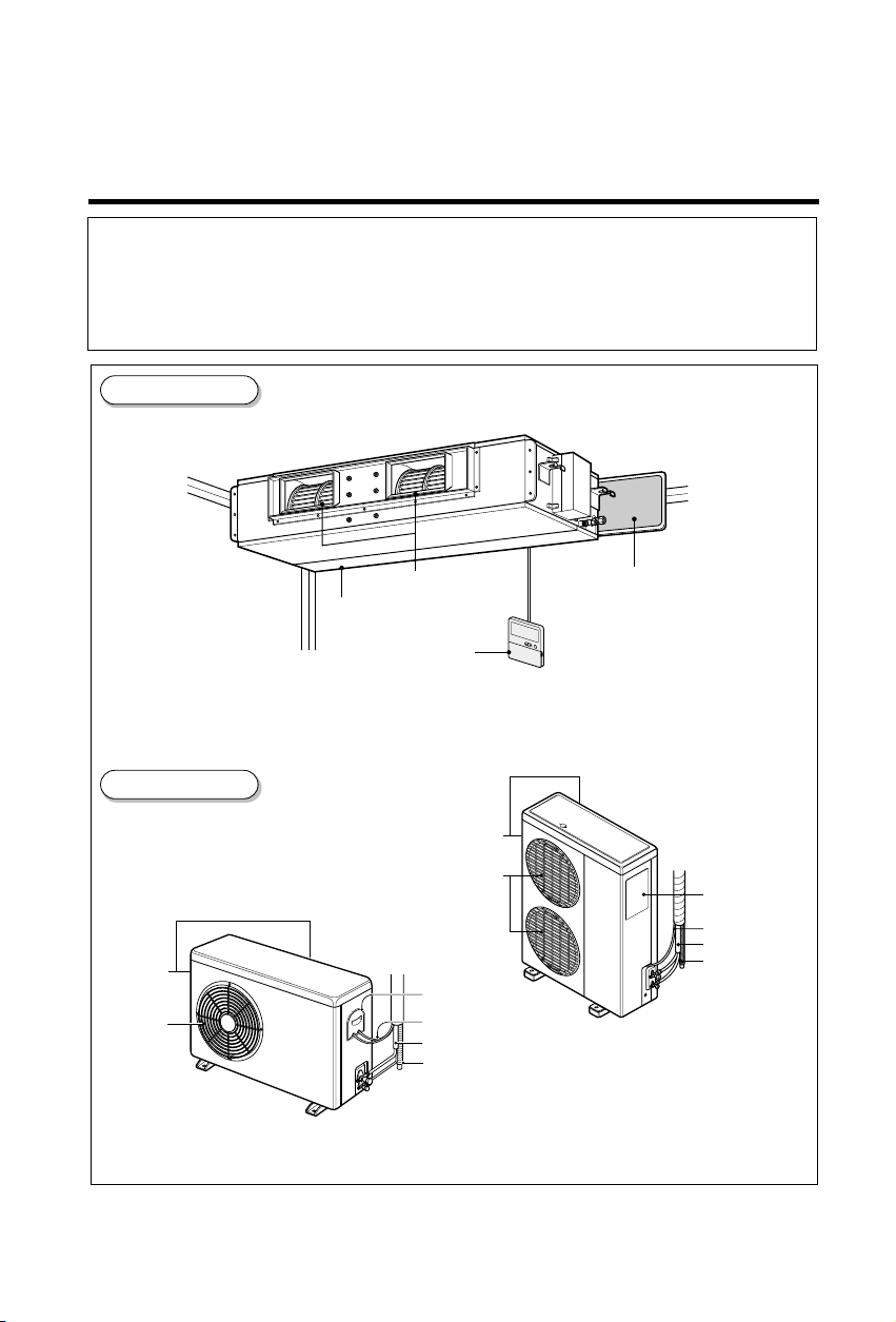
Indoor Unit
Outdoor Unit
(Side)
Air intake
vents
Air outlet
vents
Air outlet vents
Air intake vents
Remote Controller
(Rear)
(Side)
Air intake vents
Air outlet vents
Control Cover
Connecting Wire
Connection Pipe
Drain Hose
Air filters
(Rear)
Control cover
Connecting wire
Piping
Drain hose
P/No.:
MFL65000405

OUT-LINE OF INSTALLATION
1. The following should be always observed for safety ..............................3
Installation works Installation Parts Required tools
2. Installation of Indoor, Outdoor unit
1)
Selection of the best
............................4
location
2) Indoor unit installation....5
3. Connecting Pipes to the Indoor Unit
1) Preparation of Piping...14
4. Connecting Pipes to the Outdoor Unit
1) Connecting the pipes to
the Outdoor Unit ..........16
5. Checking the Drainage..............................................................................16
•
Four Type “A” screws
•
Connecting cable
•
Pipes: Gas side ..... / ", / "
Liquid side .............
•
Insulated drain hose
•
Insulation materials
•
Additional Drain hose
(Inner Dia...............25mm)
583
1
43812
/ ", / ", / "
•
Level
•
Screw driver
•
Electric drill
•
Hole core drill (ø70mm)
4
•
Flaring Tools set
6. Connecting Cables between Indoor Unit and Outdoor Unit
1) Connecting cables to the
Indoor Unit ...................17
2) Clamping of cables ......17
3) Connecting cables to the
Outdoor Unit ................18
4) Form the pipings..........19
•
Screw driver
7. Air Purging of the Connecting Pipes and the Indoor Unit ....................20
•
Hexagonal Wrench (4mm/5mm)
•
Gas-leak Detector
8. Group Control ............................................................................................21
9. Two Thermistor System ............................................................................21
1 . E.S.P (External Static Pressure) Setting................................................2
0 2
1 . How to Set E.S.P...................................................................................... 20 3
2
1. The following should be always observed for safety
• Please report to or take consent by the supply authority before connecting to the system.
• Be sure to read "THE FOLLOWING SHOULD BE ALWAYS OBSERVED FOR SAFETY" before
installing the air conditioner.
• Be sure to observe the cautions specified here as they include important items related to safety.
• The indications and meanings are as follows.
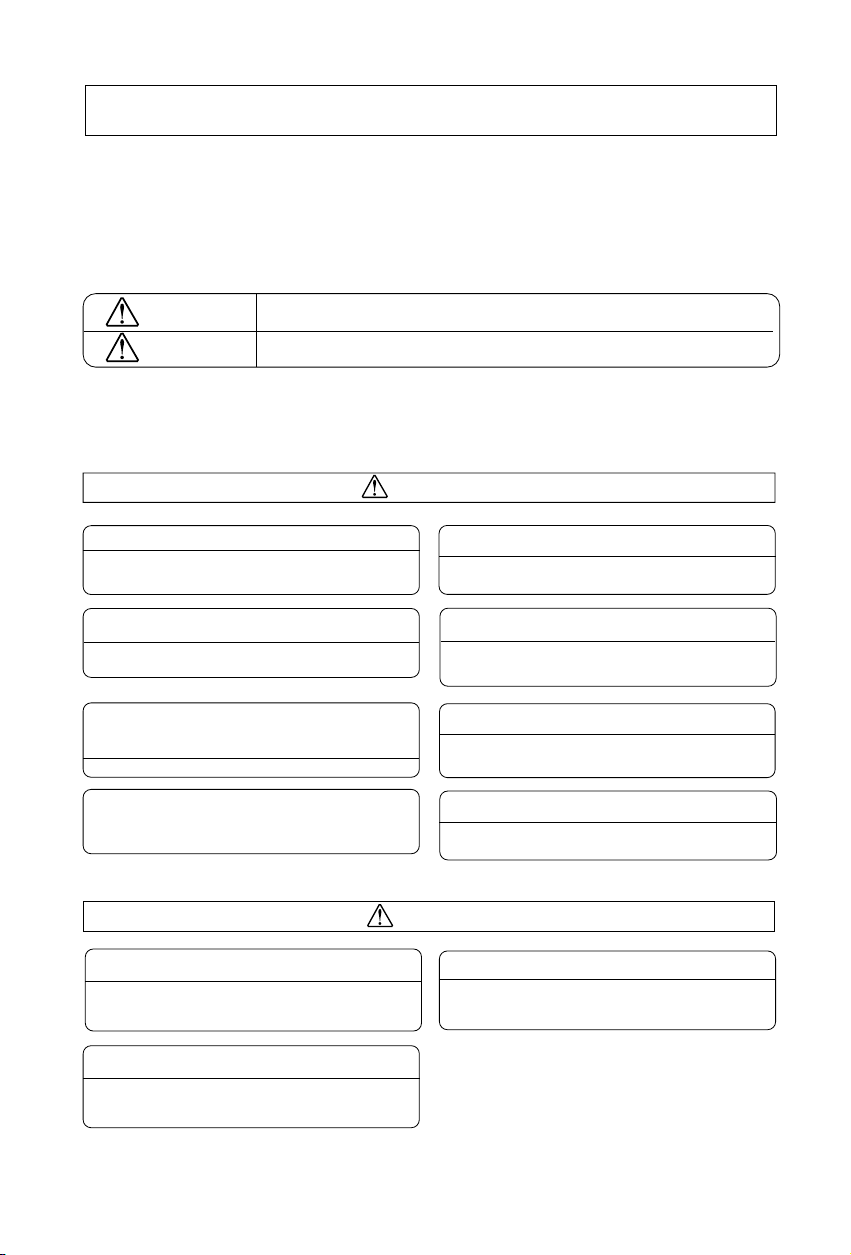
WARNING
CAUTION
Could lead to death, serious injury, etc.
Could lead to serious injury in particular environments when operated incorrectly.
• After reading this manual, be sure to keep it together with the owner's manual in an accessible
place.
WARNING
Do not install it yourself (customer).
• Incomplete installation could cause injury due to fire, electric shock,
the unit falling or a leakage of water. Consult the dealer from whom
you purchased the unit or special installer.
Install the unit securely in a place which can bear the
weight of the unit.
• When installed in an insufficient strong place, the unit could fall
causing injured.
Use the specified wires to connect the indoor and the
outdoor units securely and attach the wires firmly to
the terminal board connecting sections so the stress
of the wires is not applied to the sections.
• Incomplete connecting and fixing could cause fire.
Check that the refrigerant gas do not leak after
installation is completed.
Perform the installation securely referring to the
installation manual.
• Incomplete installation could cause a personal injury due to
fire, electric shock, the unit falling or a leakage of water.
Perform electrical work according to the installation
manual and be sure to use an exclusive circuit.
• If the capacity of the power circuit is insufficient or there is
incomplete electrical work, it could result in a fire or an electric
shock.
Attach the electrical part cover to the indoor unit and
the service panel to the outdoor unit securely.
• If the electrical par t cover if the indoor unit and/or the service
panel if the outdoor unit are not attached securely, it could result
in a fire or electric shock due to dust, water, etc.
Be sure to use the part provided or specified parts for
the installation work.
• The use of defective parts could cause an injury or leakage of
water due to a fire, electric shock, the unit falling, etc.
Perform the drainage/piping work securely
according to the installation manual.
• If there is a defect in the drainage/piping work, water
could drop from the unit and household goods could be
wet and damaged.
Do not install the electric heater
• Electric heater may cause deformation or fire of blower
and housing which were made of plastic.
CAUTION
Do not install the unit in a place where an
inflammable gas leaks.
• If gas leaks and accumulates in the area surrounding the unit, it
could cause an explosion.
3
2. Installation of Indoor, Outdoor Unit
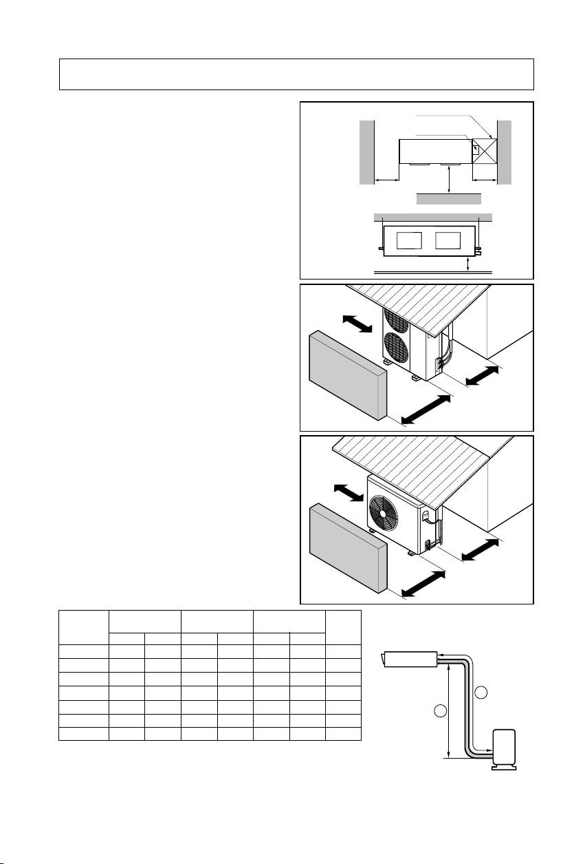
1. Selection of the best location
1) Indoor unit
Top view
(unit: mm)
Select location
Install the air conditioner in the location that
satisfies the following conditions.
• The place shall easily bear a load exceeding
four times the indoor unit’s weight.
• The place shall be able to inspect the unit as
the figure.
Front view
• The place where the unit shall be leveled.
• The place shall allow easy water
drainage.(Suitable dimension “H” is necessary
to get a slope to drain as figure.)
• The place shall easily connect with the
outdoor unit.
• The place where the unit is not affected by an
More than
30cm
electrical noise.
• The place where air circulation in the room will
be good .
• There should not be any heat source or steam
Fence or
obstacles
near the unit
2) Outdoor unit
• If an awning is built over the unit to prevent
direct sunlight or rain exposure, be careful
that heat radiation from the condenser is not
restricted.
• There should not be any animals or plants
More than
30cm
which could be affected by hot air
discharged.
• Ensure the spaces indicated by arrows from
the wall, ceiling, fence or other obstacles.
Fence or
obstacles
3) Piping length and the elevation
Capacity
18K BTU/h
24K BTU/h
30K BTU/h
36K BTU/h
42K BTU/h
48K BTU/h
60K BTU/h
Pipe Size
(Diameter: Ø)
Gas Liquid
5/8"
5/8"
5/8"
5/8"
5/8"
5/8"
3/4"
Length A(m)
Standard StandardMax. Max.
1/4"
7.5
1/4"
7.5
1/4"
7.5
3/8"
7.5
3/8"
7.5
3/8"
7.5
1/2"
7.5
• If 18K Model is installed at a distance of 15m, g of
refrigerant should be added (15-7.5) x 15g = 112.5g
• Capacity is based on standard length and maximun allowance
length is on the basis of reliability.
• Improper refrigerant charge may result in abnormal cycle.
30
30
30
30
30
30
30
Elevation B(m)
15
5
5
15
15
5
15
5
5
15
5
15
15
5
112.5
4
*Additional
refrigerant
(g/m)
15
25
35
30
0
3
45
75
Sun
Sun
Inspection hole
(600X600)
Control box
r
oof
r
oof
Indoor unit
1000
Front
More than
70cm
More than
70cm
B
600600
H
More than
30cm
More than
30cm
A
Outdoor unit
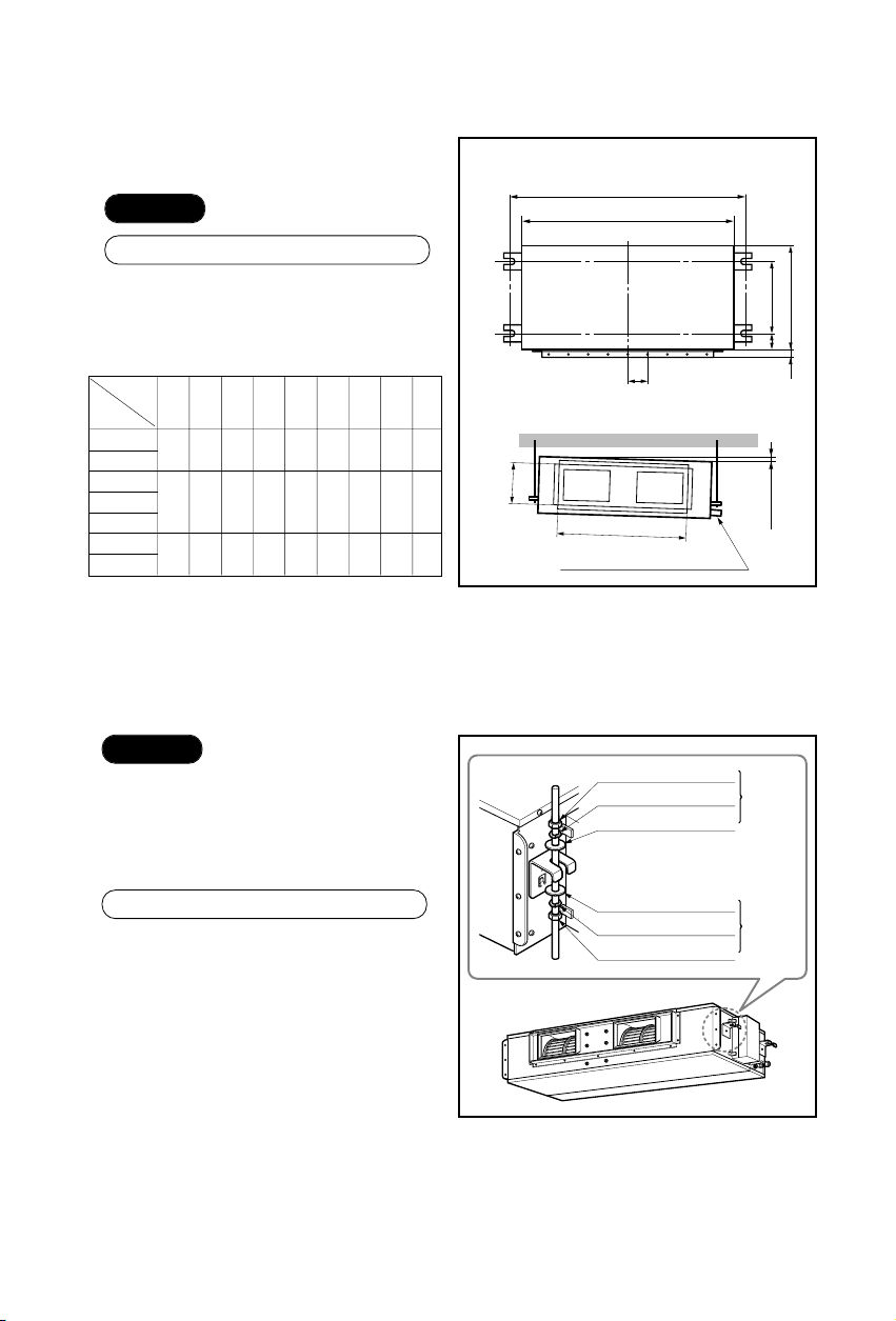
2. Indoor unit installation
■Installation of Unit
Install the unit above the ceiling correctly.
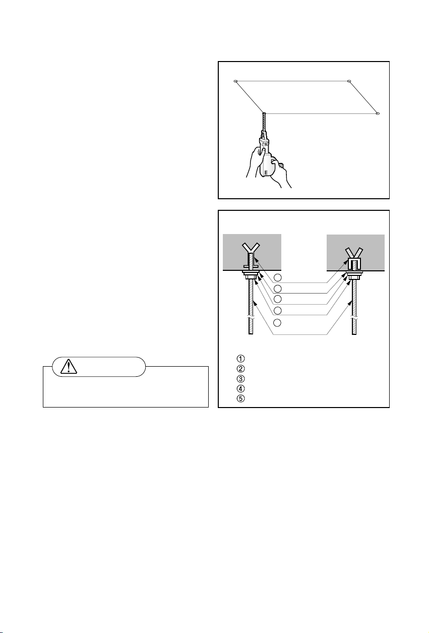
CASE 1
POSITION OF SUSPENSION BOLT
• Apply a joint-canvas between the unit and
duct to absorb unnecessary vibration.
• Apply a filter Accessory at air return hole.
(Unit:mm)
Dimension
Capacity
18K BTU/h
24K BTU/h
30K BTU/h
36K BTU/h 1180 355 45.5 450 30 87 830 184
42K BTU/h
48K BTU/h
60K BTU/h
A B C D E F (G) H I
932
880
355 45.5 450 30 87 750 16
1233
1281
1230 477 56 590 30 120 1004 294
A
B
E
CD
(G)
0
F
I
H
Drainage hole
1~3mm
CASE 2
• Install the unit leaning to a drainage hole
side as a figure for easy water drainage.
POSITION OF CONSOLE BOLT
• A place where the unit will be leveled and
that can support the weight of the unit.
• A place where the unit can withstand its
vibration.
• A place where service can be easily
performed.
M10 Nut
M10 SP. washer
M10 washer
M10 washer
M10 SP. washer
M10 Nut
X 4
X 4
X 4
X 4
X 4
X 4
(Local
supply)
(Local
supply)
5
6
• Select and mark the position for fixing
bolts.
• Drill the hole for set anchor on the face
of ceiling.
• Insert the set anchor and washer onto
the suspension bolts for locking the
suspension bolts on the ceiling.
• Mount the suspension bolts to the set
anchor firmly.
• Secure the installation plates onto the
suspension bolts (adjust level roughly)
using nuts, washers and spring
washers.
1 Set anchor
Old building New building
2 Plate washer
3 Spring washer
4 Nut
5 Suspension
bolts
Tighten the nut and bolt to prevent
unit falling
CAUTION
• Local supply
Set anchor
Plate washer - M10
Spring washer - M10
Nut - W3/8 or M10
Suspension bolt - W3/8 or M10
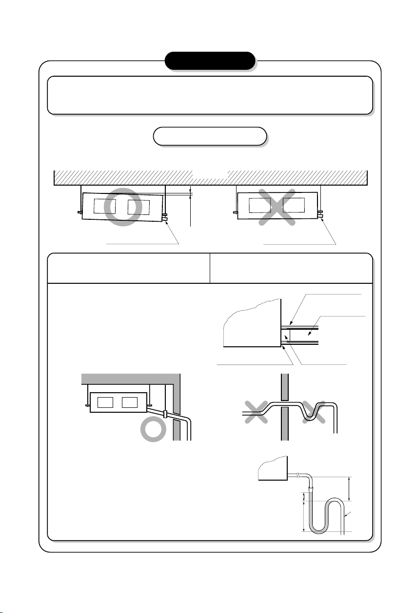
CAUTION
1. Install declination of the indoor unit is very important for the drain of the duct type air
conditioner.
2. Minimum thickness of the insulation for the connecting pipe shall be 5mm.
Front of view
• The unit must be horizontal or declined to the drain hose connected when finished
installation.
CORRECT
Drainage hole
Ceiling
1~3mm
INCORRECT
Drainage hole
CAUTION FOR GRADIENT OF
UNIT AND DRAIN PIPING
• Always lay the drain with downward
inclination (1/50 to 1/100).
Prevent any upward flow or reverse flow
in any part.
• 5mm or thicker formed thermal insulator
shall always be provided for the drain
pipe.
• Upward routing not
CORRECT
• Install the P-Trap (or U-Trap) to prevent
a water leakage caused by the blocking
of intake air filter.
Lay the drain hose with a downward
inclination so water will drain out.
Thermal insulator
Unit
Make sure to be closed.
allowed
INCORRECT
Applied U-Trap Dimension
A ≥ 70mm
B ≥ 2C
C ≥ 2 x SP
SP = External Pressure
(mmAq)
Ex) External Pressure
= 10mmAq
A ≥ 70mm
B ≥ 40mm
C ≥ 20mm
Drainage hole
C
A
(Local supply)
Drainage pipe
(Local supply)
B
U-Trap
7
8
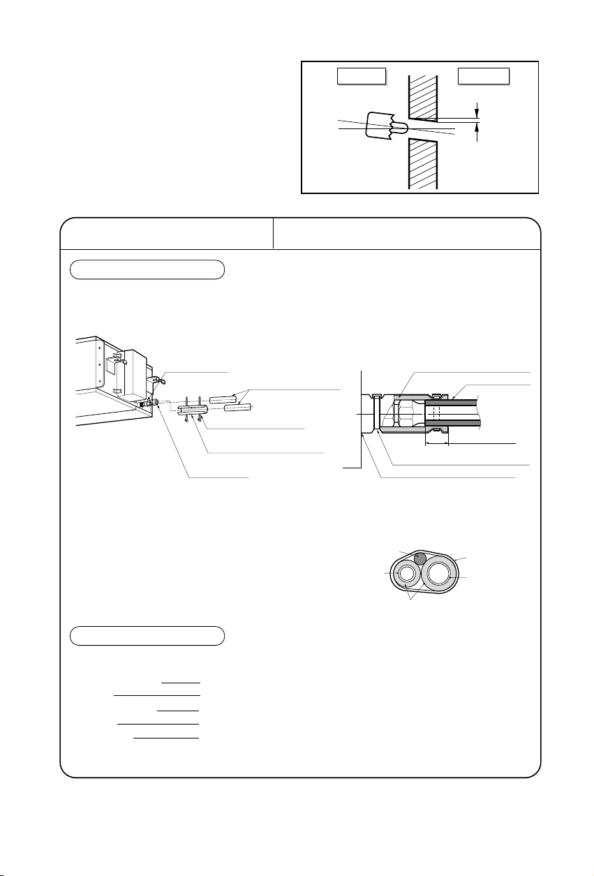
• Drill the piping hole with 70mm dia, hole
core drill.
• Piping hole should be slightly slant to the
outdoor side.
INSULATION, OTHERS
Insulate the joint and tubes completely.
All thermal insulation must comply with local requirement.
INDOOR UNIT
REFRIGERANT PIPE
• Insulate and tape both the gas piping and
liquid piping.
■ After all workings are finished, check the working and operation.
• Air distribution Is the air circulation good?
• Drain Is the drainage smoothly and no sweating?
• Gas leakage Is the piping connection correctly?
• Wiring Is the wiring connection correctly?
• Lock-bolt Is the lock-bolt of compressor loosened?
THERMAL INSULATION
TEST AND CHECK
Make sure that there is no clearance here.
Overlap with thermal
insulator for piping.
Thermal insulator for refrigerant pipe
(Local supply)
Thermal insulator for
piping(Local supply)
Hose clip for thermal insulator(Local supply)
Union for liquid pipe
Refrigerant pipe and thermal
insulator(Local supply)
Union for gas pipe
Thermal insulator for refrigerant pipe
(Local supply)
Hose clip for thermal insulator
(Local supply)
Power cable
Liquid pipe
Thermal insulator
Gas pipe
Tape
Indoor Outdoor
WALL
5~7mm
 Loading...