

Page 1
Please read this manual carefully before operating your set.
Retain it for future reference.
Record model number and serial number of the set.
See the label attached on the back cover and quote this
information to your dealer when you require service.
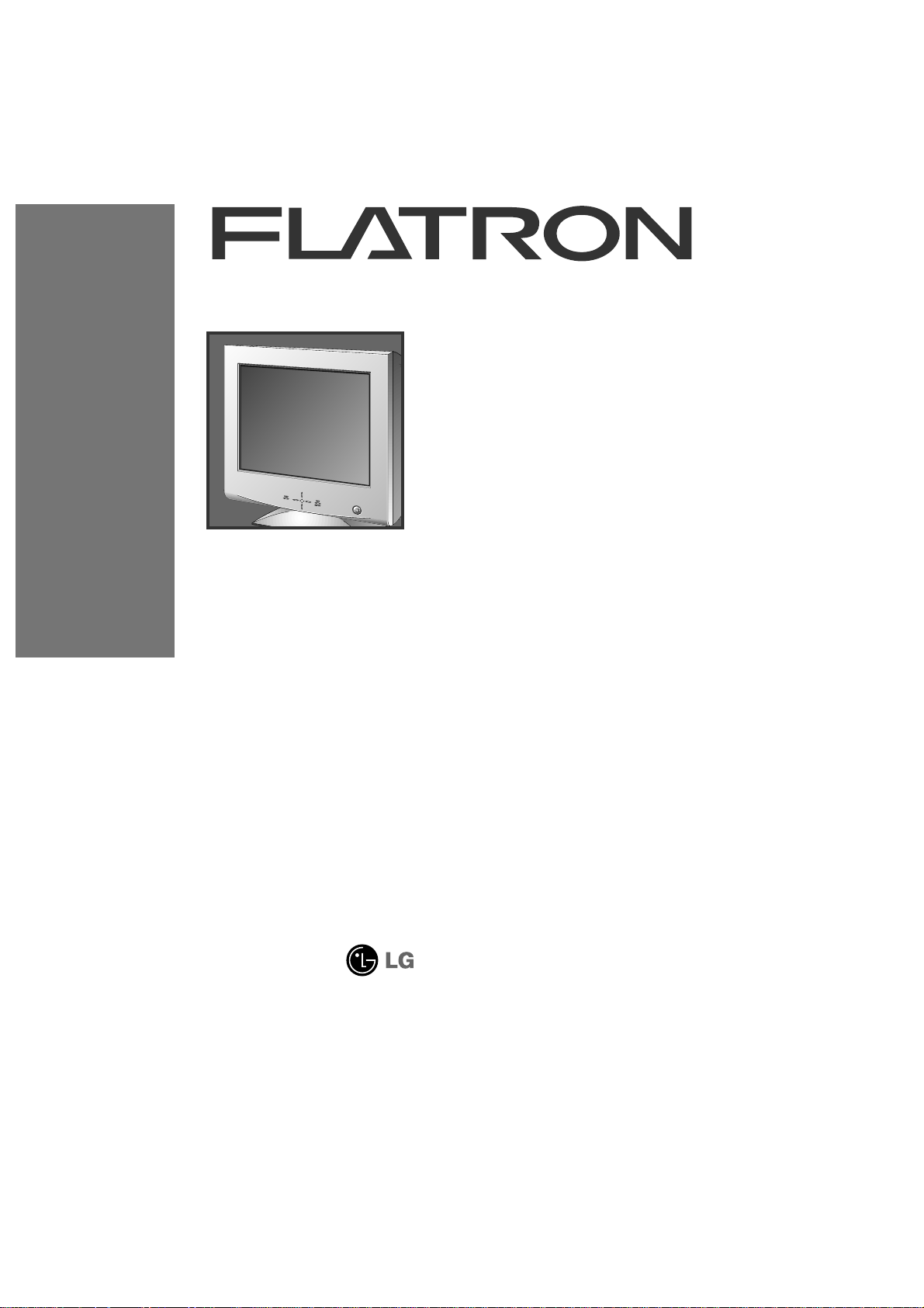
Color Monitor
915FTplus
User’s Guide
Page 2
915FT plus Monitor
User’s Guide
Page 3

Notice
Copyright © LG Electronics Inc., 1999
All Rights Reserved
This document is protected by copyright with all rights reserved.
No part of the document may be reproduced or transmitted by
any means or in any form, without prior consent in writing from
LG Electronics Inc.
Trademark Acknowledgments
LG is a trademark of LG Electronics Inc.
IBM is a registered trademark and VGA is a trademark of
International Business Machines Corporation.
Page 4

Introduction
Installation
Operation
T echnical Information
Appendix
Table of Contents
Introduction
Important Precautions
Connecting the Monitor
Making use of USB (Universal Serial Bus)
Location and Function of Controls
Control Panel Function
On Screen Display (OSD) Control Adjustment
On Screen Display(OSD) Selection and Adjustment
Energy Saving Design
Low Radiation Compliance (MPR II) and DDC (Display Data Channel)
Video Memory Modes
Troubleshooting
Service
Specifications
Communications Regulation Information
Environmental Labelling of Personal Computers
i
A1
A10
A7
A4
A2
A11
A13
A12
A17
A19
A20
A21
A22
See back of manual
See back of manual
A18
ENGLISH
Page 5
Introduction
A1
Features
Monitor Registration
The model and serial numbers are found on
the rear of this unit. These numbers are
unique to this unit and not available to
others. You should record requested
information here and retain this guide as a
permanent record of your purchase. Staple
your receipt here.
Date of Purchase :
Dealer Purchased From
:
Dealer Address :
Dealer Phone No. :
Model No. :
Serial No. :
Introduction
Thank you for purchasing a high resolution monitor. It will give you
high resolution performance and convenient reliable operation in a
variety of video operating modes.
The monitor is a 19 inches (18.0 inches viewable ) intelligent,
microprocessor based monitor compatible with most analog RGB (Red,
Green, Blue) display standards, including IBM PC®, PS/2®, Apple®,
Macintosh®, Centris®, Quadra®, and Macintosh II family.
USB (Universal Serial Bus) ports at the back of the monitor are prepared
for the USB cable and hub. You can easily and flexibly connect USBdesigned devices-such as a mouse, keyboard or printer- to the monitor
for true Plug and Play function.
The monitor provides crisp text and vivid color graphics with VGA,
SVGA, XGA, and VESA Ergonomic modes (non-interlaced), and most
Macintosh compatible color video cards when used with the appropriate
adaptor. The monitor's wide compatibility makes it possible to upgrade
video cards or software without purchasing a new monitor.
Digitally controlled auto-scanning is done with the micro-processor for
horizontal scan frequencies between 30 and 107kHz, and vertical scan
frequencies between 50-200Hz. The microprocessor-based intelligence
allows the monitor to operate in each frequency mode with the
precision of a fixed frequency monitor.
We accomplished to adapt the advanced design and technology to the
monitor. Soft touch buttons on the front panel are simple and allow you
to conveniently adjust a variety of image controls. The absolute flat
screen and screen surface treatment eliminate distracting glares.
This monitor is capable of producing a maximum horizontal resolution of
1600 dots and a maximum vertical resolution of 1200 lines. It is well
suited for CAD work and sophisticated windowing environments.
For low cost of monitor operation, this monitor is certified as meeting
the EPA Energy Star requirements, and utilizes the VESA Display Power
Management Signalling (DPMS) protocol for power saving during nonuse periods.
Page 6
Operation
A2
Introduction
On Safety
Important Precautions
This unit has been engineered and manufactured to assure your
personal safety, but impr oper use can r esult in potential electrical
shock or fire hazard. In order not to defeat the safeguards
incorporated in this monitor, observe the following basic rules for its
installation, use, and servicing. Also follow all warnings and
instructions marked directly on your monitor.
Use only the power cord supplied with the unit. In case you use another
power cord, make sure that it is certified by the applicable national
standards if not being provided by the supplier.
If the power cable is
faulty in any way, please contact the manufacturer or the nearest
authorized repair service provider for a replacement.
Operate the monitor only from a power source indicated in the
specifications of this manual or listed on the monitor. If you are not sure
what type of power supply you have in your home, consult with your dealer.
Overloaded AC outlets and extension cords are dangerous. So are frayed
power cords and broken plugs. They may result in a shock or fire hazard.
Call your service technician for replacement.
Do not Open the Monitor
There are no user serviceable components inside.
There are Dangerous High Voltages inside, even when the power is
OFF.
Contact your dealer if the monitor is not operating properly.
To Avoid Personal Injury :
Do not place the monitor on a sloping shelf unless properly secured.
Use only a stand recommended by the manufacturer.
Do not try to roll a stand with small casters across thresholds or deep
pile carpets.
To Prevent Fire or Hazards:
Always turn the monitor OFF if you leave the room for more than a
short period of time. Never leave the monitor ON when leaving the
house.
Keep children from dropping or pushing objects into the monitor's
cabinet openings. Some internal parts carry hazardous voltages.
Page 7

Operation
A3
Introduction
On Installation
On Cleaning
On Repacking
Important Precautions
Do not add accessories that have not been designed for this monitor.
During a lightning storm or when the monitor is to be left unattended
for an extended period of time, unplug it from the wall outlet.
Do not bring magnetic devices such as magnets or motors near the
picture tube.
Do not allow anything to rest upon or roll over the power cord, and do not
place the monitor where the power cord is subject to damage.
Do not use this monitor near water such as near a bathtub, washbowl,
kitchen sink, laundry tub, in a wet basement, or near a swimming pool.
Monitors are provided with ventilation openings in the cabinet to allow the
release of heat generated during operation. If these openings are blocked,
built-up heat can cause failures which may result in a fire hazard.
Therefore, NEVER:
Block the bottom ventilation slots by placing the monitor on a bed,
sofa, rug, etc.
Place the monitor in a built-in enclosure unless proper ventilation is
provided.
Cover the openings with cloth or other material.
Place the monitor near or over a radiator or heat source.
Unplug the monitor before cleaning the face of the picture tube.
Use a slightly damp (not wet) cloth. Do not use an aerosol directly on
the picture tube because overspray may cause electrical shock.
Do not throw away the carton and packing materials. They make an
ideal container in which to transport the unit. When shipping the unit
to another location, repack it in its original material.
Page 8
Installation
A4
Connection to any IBM
VGA PC compatible
system
Connecting the Monitor
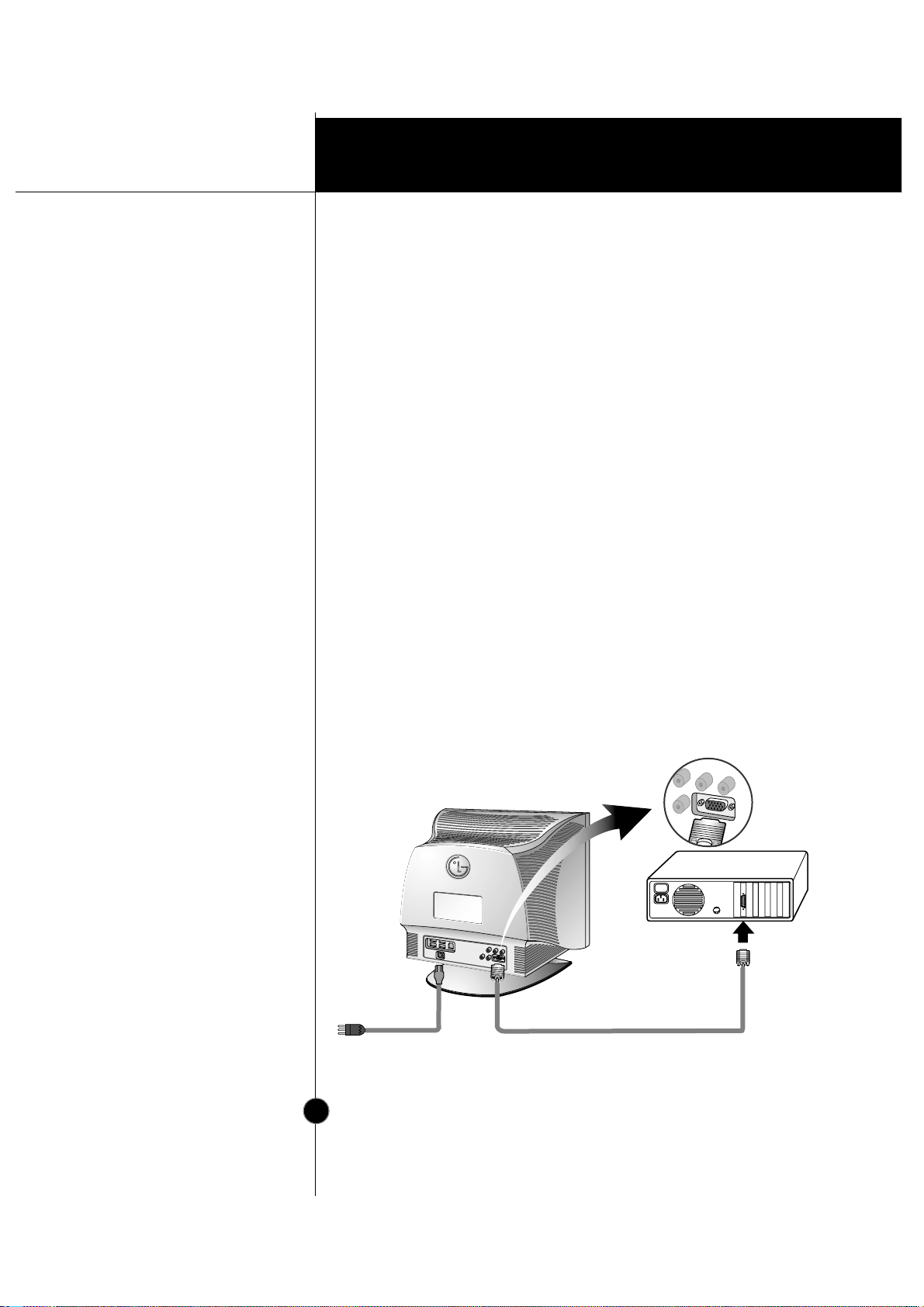
Figure 1 shows the signal cable connections from the monitor to the
Video Graphics Array (VGA) port typical in an IBM PC or PC
compatible. This also applies to any graphics video card for PC-CAD
or workstation that has a 15 pin high density (3 row) d-Sub connector.
1. Power off both the monitor and PC.
2. Connect the 15 pin VGA connector of the supplied signal cable to the
output VGA video connector on the PC and the matching input
connector on the rear of the monitor. The connectors will mate only
one way. If you cannot attach the cable easily, turn the connector
upside down and try again. When mated, tighten the thumbscrews to
secure the connection.
3. Power ON the PC, then the monitor.
4. If you see the NO SIGNAL message, check the signal cable and
connectors.
5. After using the system, power OFF the monitor, then the PC.
Figure 1.
Power Cord
Signal Cable
D-15P
Page 9
Installation
A5
Connecting to an Apple
Macintosh PC
Connecting the Monitor
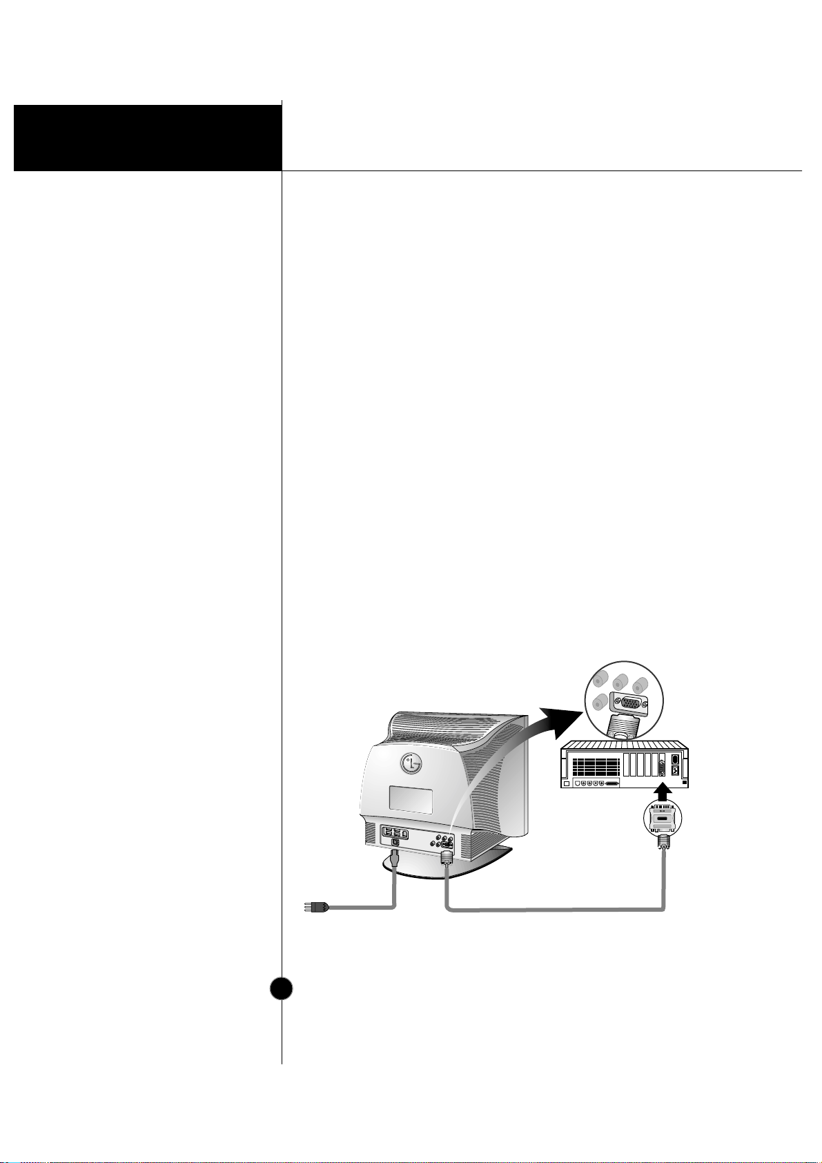
Figure 2 shows the connection to an Apple Macintosh, using a
separately purchased adapter.
1. Power OFF both the monitor and the PC.
2. Locate the appropriate MAC to VGA adapter block at your local
computer store. This adapter changes the high density 3 row 15 pin
VGA connector to the correct 15 pin 2 row connection to mate with
your MAC. Attach the other end of the signal cable to the side of the
adapter block with 3 rows.
3. Connect the attached adapter block/signal cable to the video output on
your MAC.
4. Power ON the PC, then the monitor.
5. If you see the NO SIGNAL message, check the signal cable and
connectors.
6. After using the system, power OFF the monitor, then the PC.
Figure 2.
MAC6MAC6
Power Cord
Signal Cable
D-15P
Adapter 15P
Page 10
Installation
The Other T ypes of V ideo
Cards with BNC
Connectors
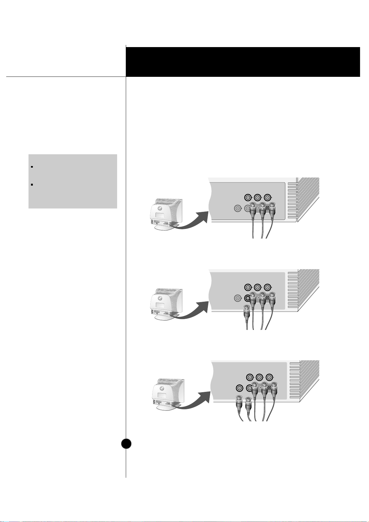
* HD : Horizontal Drive
VD : Vertical Drive
COMP : Composite
Connecting the Monitor
Notes on using the BNC connectors with other types of video cards.
Follow the example that fits your needs.
1. In case of composite sync on green video signal(Sync On Green):
Connect R,G and B video signals to BNC receptacles on the back of
the monitor, respectively.
2. In case of external composite sync signal:
Connect R, G and B video signals and Composite sync signal to BNC
receptacles on rear panel, respectively.
3. In case of separate horizontal and vertical sync signals:
Connect R, G and B video signals and horizontal and vertical sync
signals to BNC receptacles on rear panel respectively.
A6
NOTE
This package does not have BNC
Connectors but you can purchase it at
your local computer store.
This monitor will not support the DDC
function, if you are using the 5 BNC
connectors with other types of video
cards.
B
G
R
COMP.
VD
HD
D-SUB
GreenBlue
Red
B
G
R
COMP.
VD
HD
D-SUB
Gray
Green
Blue
Red
BGR
COMP.
VD
HD
Blue
Green
Red
Black Gray
Page 11
Installation
USB connection
A7
Making use of USB (Universal Serial Bus)
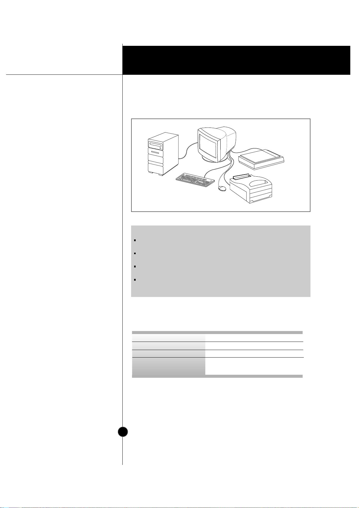
USB (Universal Serial Bus) is an innovation in connecting your different
desktop peripherals conveniently to your computer . By using the USB,
you will be able to connect your mouse, keyboard, printer , and other
peripherals to your monitor instead of having to connect them to your
computer . This will give you gr eater flexibility in setting up your system.
USB allows you to connect chain up to 120 devices on a single USB port,
and you can “hot” plug (attach them while the computer is running) or
unplug them while maintaining Plug and Plug auto detection and
configuration. This monitor has an integrated self-powered USB hub,
allowing up to 4 other USB devices to be attached it.
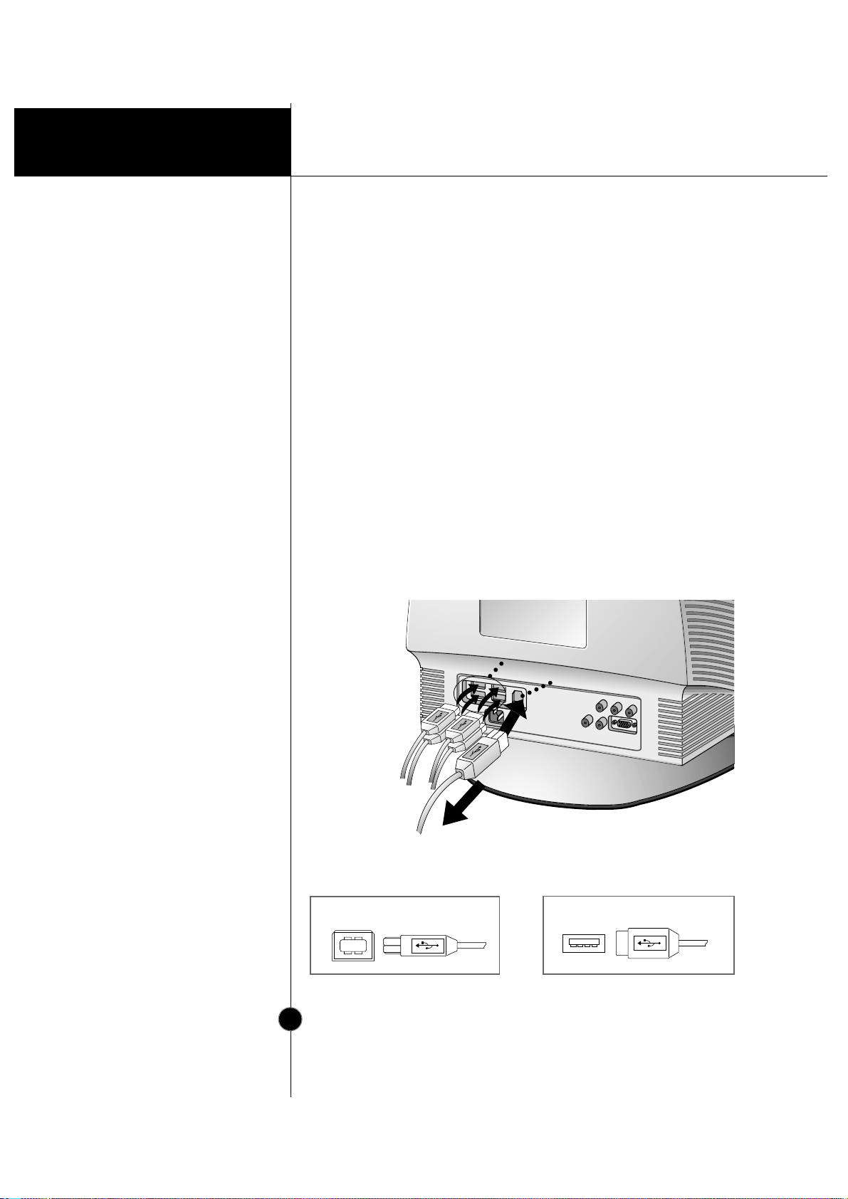
1. Connect the upstream port of the monitor to the downstream port of
the USB compliant PC or another hub using the USB cable (Computer
must have a USB port).
2. Connect the USB compliant peripherals to the downstream ports of
the monitor.
USB Upstream connector
USB Downstream connector
USB upstream Port
USB downstream Ports
connect the cables from USB
compliant peripherals-such as
keyboard, mouse, printer,
scanner, etc
To USB downstream port of
the USB compliant PC or
another hub cable
keyboard
printer
mouse
etc.
Page 12
Installation
USB specifications
A8
Making use of USB (Universal Serial Bus)
Example of connection
keyboard
printer
scanner
monitor
computer
mouse
USB standard
Downstream power supply
Communication speed
USB port
Rev. 1.0 complied self-powered hub
500mA for each (MAX)
12 Mbps (full), 1.5 Mbps (low)
1 Upstream port
4 Downstream ports
NOTE
To activate the USB hub function, the monitor must be connected to a USB
compliant PC(OS) or another hub with the USB cable(enclosed).
When connecting the USB cable, check that the shape of the connector at the
cable side matches the shape at the connecting side.
When the monitor is not plugged into an electric socket, the peripherals
connected to the downstream ports will not operate.
Even if the monitor is in a power saving mode, USB compliant devices will
function when they are connected the USB ports(both the upstream and
downstream) of the monitor.
Page 13
Installation
USB-Monitor Software
function
A9
Making use of USB (Universal Serial Bus)
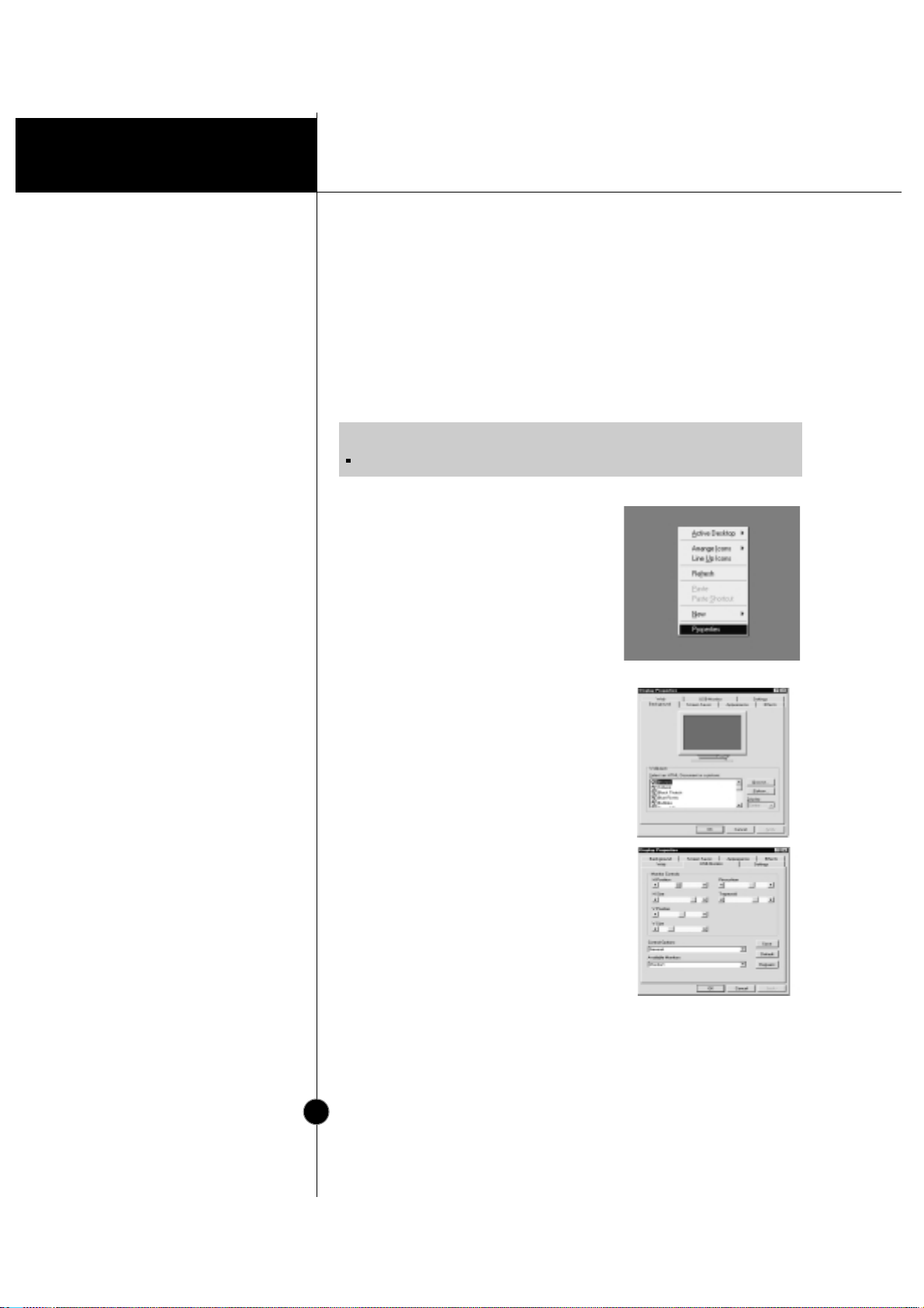
As an added advantage, the monitor can be controlled from a
computer with a mouse or keyboard. Making adjustments to the
image size, position, screen color and operating parameters of the
monitor is easy with the USB-Monitor software (please refer to the
supplied disk).
To access the USB-Monitor software
function:
1. Click the right button of the mouse,
then select the Properties.
The Display Properties windows
appears, as shown in the figure.
2. Click the USB-Monitor.
You can select and adjust the Control
Options (General, Color and
Advanced).
3. When you are finished the making
changes, click the Save.
To reset the image without applying
changes, click the Default.
Degauss removes magnetic field
buildup that can be affect color purity
and convergence.
4. To close the window, click OK.
NOTE
USB-Monitor software function is supported Windows 98 and higher.
Properties
Display Properties
Page 14
Operation
Front View
Rear View
A10
Location and Function of Controls
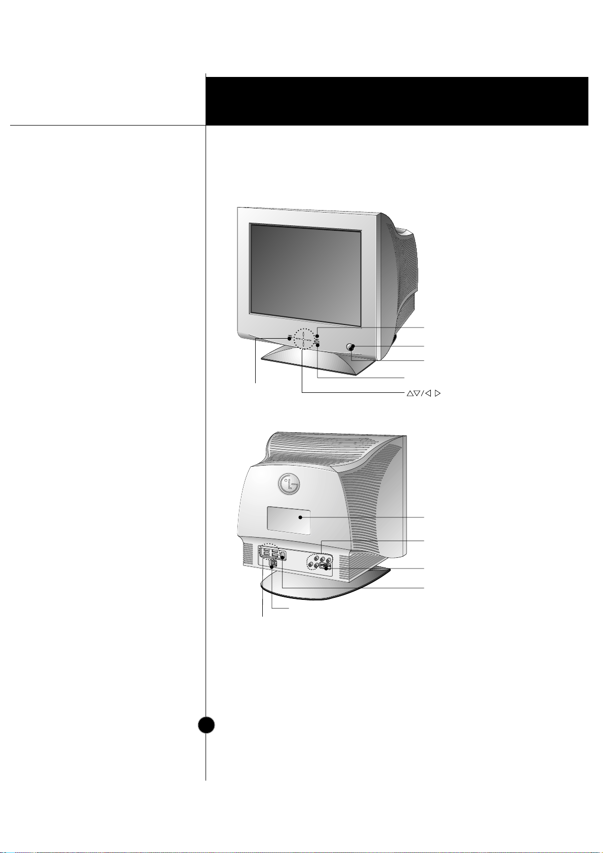
ID Label
BNC Signal Connectors
USB upstream port
USB downstream ports
D-Sub Signal Connector
AC Power Socket
Power Button
SET Button
Power Indicator
OSD Button
Buttons
INPUT Button
Page 15
Operation
Front Panel Controls
A11
Control Panel Function
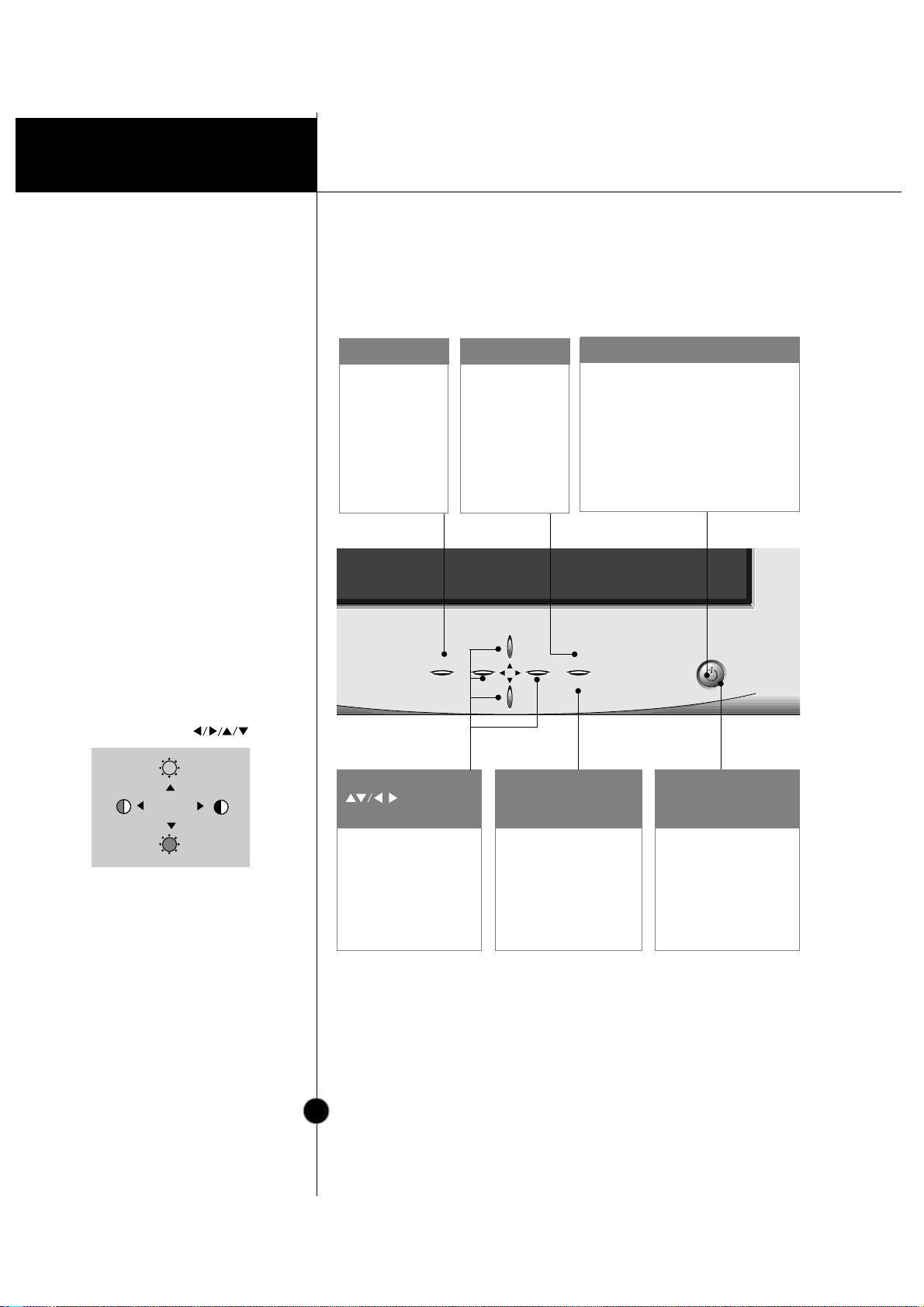
Use this button to
enter or exit the
on screen display.
OSD Button
Use this button to
enter a selection
in the on screen
display.
SET Button
Use these buttons to
choose or adjust items
in the on screen display.
Buttons
Use this button to select
video input (D-sub or
BNC).
INPUT Button
Use this button to turn
the monitor on or off.
Power Button
The power indicator light is shown in
the power button. This indicator lights
up green when the monitor operates
normally. If the monitor is in DPM
(Energy Saving) mode (stand-by/
suspend/ off), this indicator color
changes to amber.
Power Indicator
OSD SET
INPUT
<Shortcut Keys>
• To adjust brightness and contrast
directly, press the button.
You can also adjust the contrast and
brightness by selecting
[BRIGHTNESS CONTRAST] from
the OSD main menu.
• To select video input (D-sub or BNC)
directly, press the INPUT button.
Page 16
Operation
A12
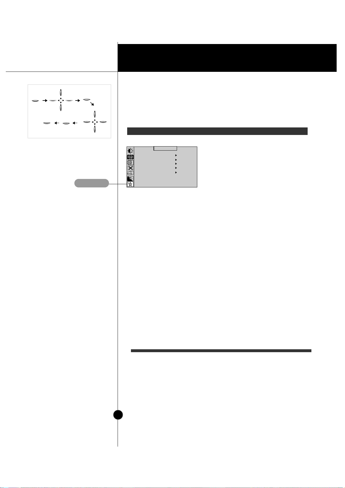
On Screen Display (OSD) Control Adjustment
Making adjustments to the image size, position and operating
parameters of the monitor are quick and easy with the On Screen
Display Control system. A quick example is given below to familiarize
you with the use of the controls. Following section is an outline of the
available adjustments and selections you can make using the OSD.
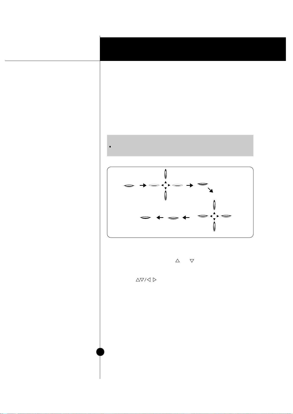
To make adjustments in the On Screen Display, follow these steps:
Touch the OSD Button, then the main menu of the OSD appears.
To acces a control, use the or Buttons. When the icon you
want becomes highlighted, touch the SET Button.
Use the Buttons to adjust the item to the desired level.
Accept the changes by touching the SET Button.
Exit the OSD by touching the OSD Button.
OSD
SET
INPUT
INPUT
SET
OSD
NOTE
Allow the monitor to stabilize for at least 30 minutes before making image
adjustment.
1
1
2
1
2
3
1
2
3
4
1
1
2
2
3
3
4
4
5
5
Page 17
Operation
A13
On Screen Display(OSD) Selection and
Adjustment
You were introduced to the procedur e of selection and adjusting an
item using the OSD system.
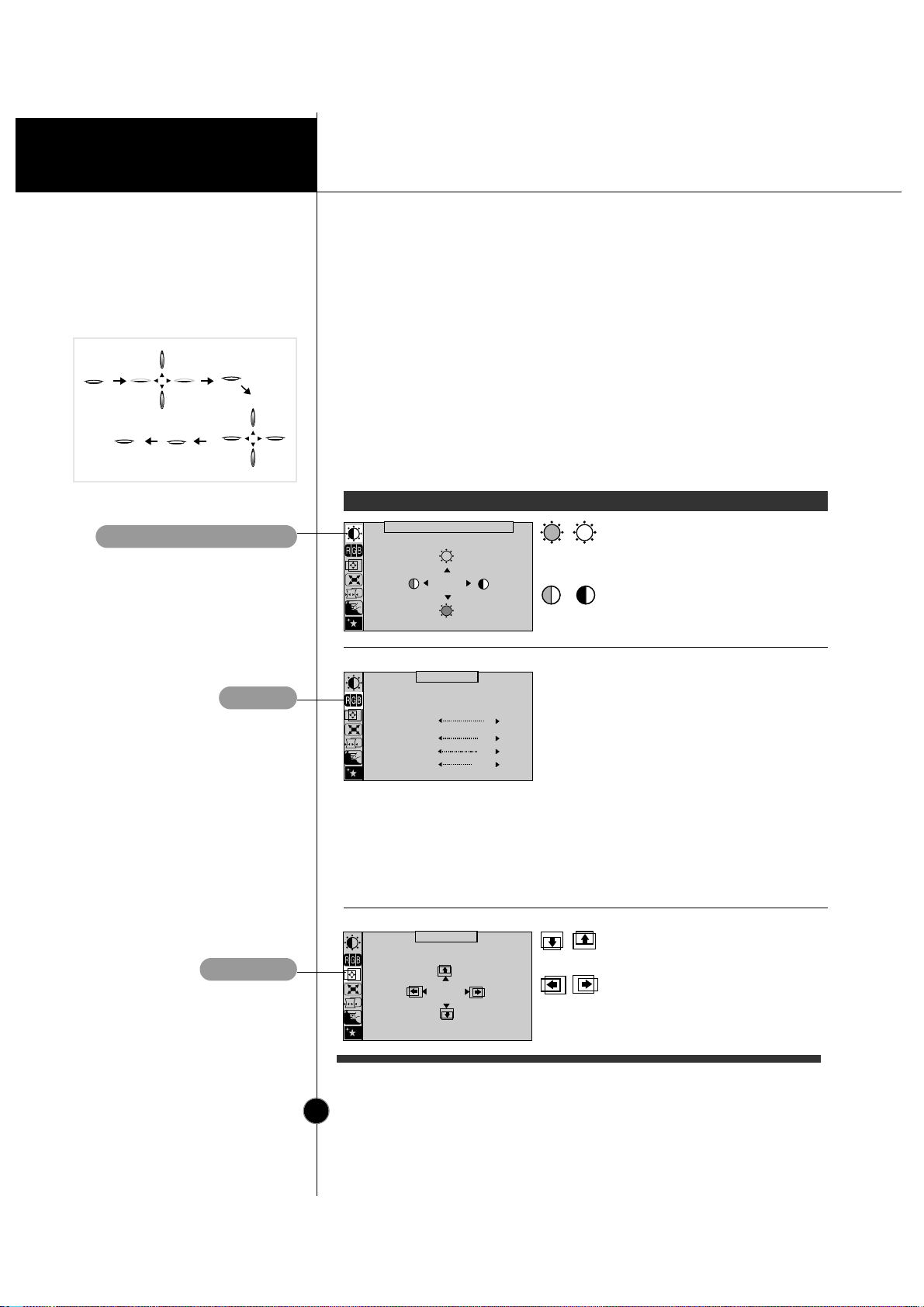
Listed below are the icons, icon names, and icon descriptions of the
items that are shown on the Menu.
OSD Adjust Description
BRIGHTNESS CONTRAST
66
92
COLOR
PRESET
TEMP
RED
GREEN
BLUE
6500K 9300K
POSITION
66
45
Brightness
Used to adjust the brightness of the
screen.
Contrast
Adjust the display to the contrast
desired.
PRESET
TEMP
RED
GREEN
BLUE
6500K/ 9300K
To appear the displays color
temperature.
•6500K:Slightly reddish white.
•9300K:Slightly bluish white.
User easily color set without
adjustment Red, Green and Blue
(R/G/B).
To set your own color levels.
To set your own color levels.
To set your own color levels.
Vertical Position
To move image up and down.
Horizontal Position
To move picture image left and
right.
OSD
SET
INPUT
INPUT
SET
OSD
BRIGHTNESS/CONTRAST
COLOR
POSITION
Page 18
Operation
A14
On Screen Display(OSD) Selection and
Adjustment
OSD Adjust Description
SIZE
49
64
SHAPE
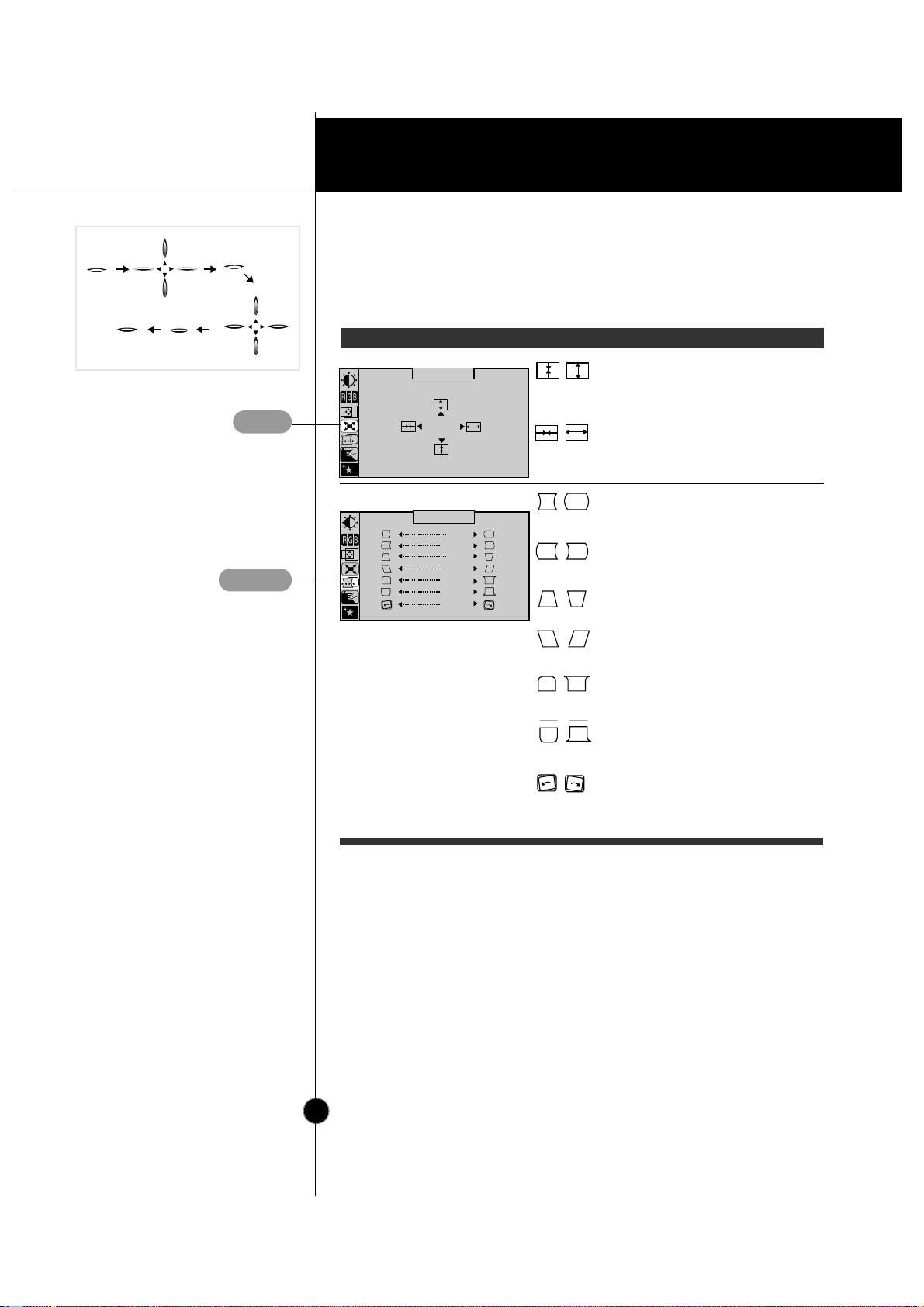
Vertical Size
To adjust image height.
Horizontal Size
To adjust image width.
Side Pincushion
To correct the bowing in and out of the
image.
Side pincushion balance
To correct the balance of both sides
bowing.
Trapezoid
To correct geometric distortion.
Parallelogram
This control adjusts for a skewing
of the screen image.
Tilt
To correct image rotation.
Top Corner
To correct the irregular distortion of
the displayed image.
Bottom Corner
To correct the irregular distortion of
the displayed image.
SIZE
SHAPE
OSD
SET
INPUT
INPUT
SET
OSD
Page 19
On Screen Display(OSD) Selection and
Adjustment
OSD
SET
INPUT
INPUT
SET
OSD
Technical Information
A15
OSD Adjust Description
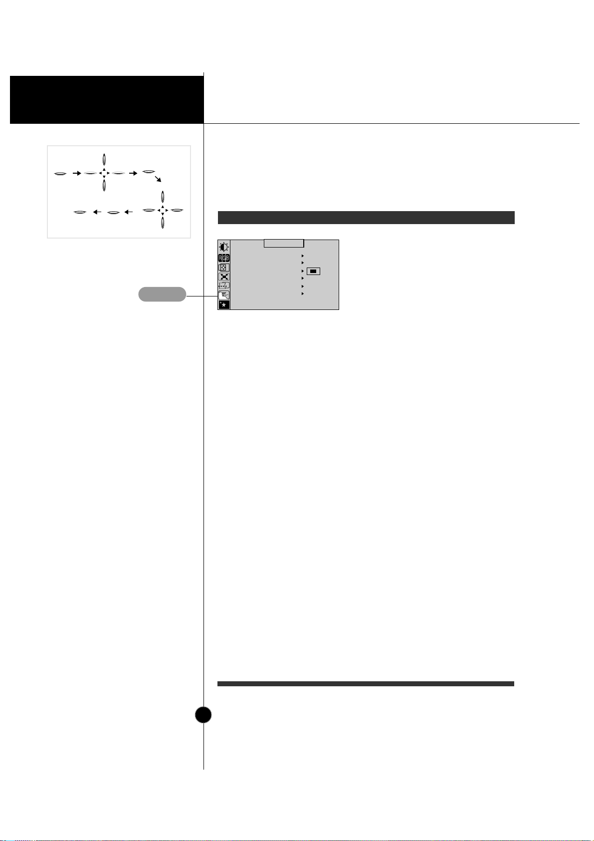
VIDEO LEVEL 0.7V
LANGUAGE ENGLISH
BEEP ON
INPUT SELECT D SUB
CLAMP
SEPARATE
OSD POSITION
SETUP
This item is used to select the
monitor's input signal level. The
normal level used for most PC's
is 0.7V.
When the screen suddenly gets
brightened or blurry, please
select 1.0V and try again.
To choose the language in which
the control names are displayed.
OSD Menus are available in 8
language: English, Deutsch,
Français, Español, Italiano,
Svenska, Suomi and Português.
To adjust position of the OSD
window on the screen.
To select beep ON or OFF.
To select D-sub or 5 BNC.
In case of input SOG(Sync On
Green) Video Signal, the back
raster will appear the green.
Then, to select the SOG(Sync
On Green) in the clamp, will take
you back to the original back
raster.
VIDEO LEVEL
LANGUAGE
OSD POSITION
BEEP
INPUT
SELECT
CLAMP
SETUP
Page 20
Operation
A16
On Screen Display(OSD) Selection and
Adjustment
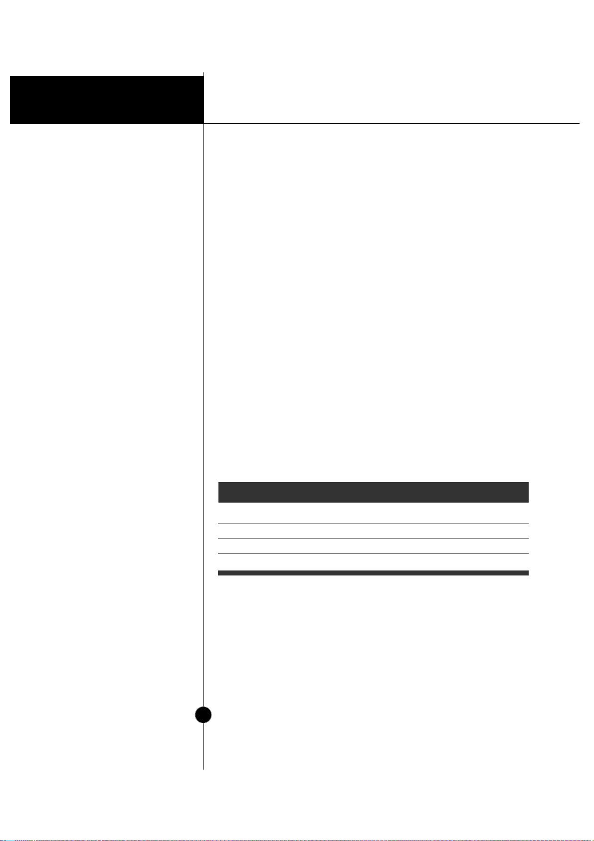
OSD Adjust Description
To manually demagnetize the
screen which may show some
image or color incorrectly.
SPECIAL
DEGAUSS ON
RECALL OFF
MOIRE H: 0/V: 0
CONVERGENCE H:50/V:50
PURITY 50
54.4kHz/60.0Hz
USER MODE
DEGAUSS
If the monitor is operating in a
factory preset mode, this control
will reset the image to the factory
preset mode.
RECALL
This item allows you to reduce the
moire (Moire is caused by
interference Horizontal Scan Line
with the periodical dot screen). It is
normally OFF(H:0/V:0).
The moire adjustments may affect
the focus of the screen.
The screen image may shake
slightly while the moire reduction
function is on.
MOIRE
Use to adjust the alignment of red
and blue fields.
CONVERGENCE
Use to adjust the overall purity of
the image if the color appears
uneven.
PURITY
OSD
SET
INPUT
INPUT
SET
OSD
SPECIAL
Page 21
Technical Information
A17
Power Consumption
Energy Saving Design
This monitor complies with the EPA's Energy Star program, which is a
program designed to have manufacturers of computer equipment build
circuitry into their products to reduce power consumption during time of
non-use.
This monitor also goes into its energy saving mode if you exceed the
monitor's operating limits, such as the maximum resolution of 1600x1200
or the frequency refresh rates of 30-107kHz horizontal or 50-200Hz
vertical. When this monitor is used with a Green or EPA Energy Star PC,
or a PC with a screen blanking software following the VESA Display
Power Management Signalling (DPMS) protocol, this monitor can
conserve significant energy by reducing power consumption during
periods of non-use. When the PC goes into the energy saving mode, the
monitor will go into a suspended operation state, indicated by the Power
LED light changing from a green color to an amber color. After an
extended period in the suspended mode, the monitor will then enter a
semi-OFF mode to conserve more energy. In the semi-OFF mode or
DPMS OFF mode as we call it in our specifications, the Power LED will
still show an amber color. When you awaken your PC by hitting a key or
moving the mouse, the monitor will also awaken to its normal operating
mode, indicated by the green Power LED light. By following these
conventions, the power consumption can be reduced to the following
levels:
Mode
Normal(Max.)
Stand-by
Suspend
Off
Hori.
Sync
On
Off
On
Off
Verti.
Sync
On
On
Off
Off
Video
Normal
Off
Off
Off
Power
Consumption
≤ 140W
≤ 8W
≤ 8W
≤ 3W
LED Color
Green
Amber
Amber
Amber
Page 22
Technical Information
A18
Low Radiation Compliance
(MPR II)
DDC (Display Data
Channel)
Low Radiation Compliance (MPR II) and
DDC (Display Data Channel)
This monitor meets one of the strictest guidelines available today for low
radiation emissions, offering the user extra shielding and an antistatic
screen coating. These guidelines, set forth by a government agency in
Sweden, limit the amount of emission allowed in the Extremely Low
Frequency (ELF) and Very Low Frequency (VLF) electromagnetic range.
DDC is a communication channel over which the monitor automatically
informs the host system (PC) about its capabilities. This monitor has two
DDC function; DDC1 and DDC2B. DDC1 and DDC2B carry out unidirectional communication between the PC and the monitor. Under these
situations, the PC sends display data to the monitor but not commands to
control the monitor settings.
NOTE
PC must support DDC functions to do this.
If your monitor is displaying a mono chrome image or the wrong resolution,
select the DDC OFF function.
Page 23
A19
Technical Information
Display Modes
(Resolution)
User Modes
Recalling Display Modes
Video Memory Modes
The monitor has 39 memory locations for display modes, 13 of which
are factory preset to popular video modes.
Modes 14-39 are empty and can accept new video data. If the monitor
detects a new video mode that has not been present before or is not
one of the preset modes, it stores the new mode automatically in one
of the empty modes starting with mode 14.
If you use up the 26 blank modes and still have more new video
modes, the monitor replaces the information in the user modes starting
with mode 14.
When your monitor detects a mode it has seen before, it automatically
recalls the image settings you may have made the last time you used
that mode.
You may, however, manually force a recall of each of the 13 preset
modes by pressing the Recall button. All preset modes are
automatically recalled as the monitor senses the incoming signal.
The ability to recall the preset modes is dependent on the signal
coming from your PC’s video card or system. If this signal does not
match any of the factory modes, the monitor automatically sets itself to
display the image.
1
2
3
4
5
6
7
8
9
10
11
12
13
720 x 400
640 x 480
640 x 480
800 x 600
1024 x 768
1152 x 864
1024 x 768
1280 x 1024
1280 x 1024
1600 x 1200
1600 x 1200
832 x 624
1152 x 870
31.469
31.469
43.269
53.674
60.023
67.500
68.677
79.976
91.146
93.750
106.250
49.725
68.681
70
60
85
85
75
75
85
75
85
75
85
75
75
Yes
Yes
Yes
Yes
Yes
Yes
Yes
Yes
Yes
Yes
Yes
Yes
Yes
Display Modes (Resolution)
Horizontal Freq.(kHz) Vertical Freq.(Hz) Recall
VESA
VESA
VESA
VESA
VESA
VESA
VESA
VESA
VESA
VESA
VESA
APPLE
APPLE
Page 24
A20
Technical Information
Troubleshooting
Check the following before calling for service.
NO SIGNAL message.
The signal cable is not connected.
The power LED is illuminated amber .
The frequency of the sync input is outside the operating range of the
monitor.
*Horizontal Frequency : 30-107kHz
*Vertical Frequency : 50-200Hz
Use the graphics board's utility software to change the frequency
setting (Refer to the manual for graphics board).
Display power management mode.
These is no sync signal.
The signal cable is not fastened securely.
Check the computer power and graphics adapter configuration.
The image on the SCREEN is not centered, or too small,
or not a rectangle shape.
Image adjustment not been done yet in the current operating mode.
Use the OSD, SET and buttons to set the image to your liking.
The monitor doesn't enter the power saving off mode
(Amber).
Computer video signal is not VESA DPMS standard. Either the PC or
the video controller card is not using the VESA DPMS power
NOTE
If the power indicator(LED) light is blinking amber, may result in abnomal
condition of the monitor.
Then press a power ON/OFF button on the front panel control and call your
service technician for more information.
Page 25

A21
Technical Information
Service
Unplug the monitor from the wall outlet and refer servicing to
qualified service personnel when :
The power cord or plug is damaged or frayed.
Liquid has been spilled into the monitor.
The monitor has been exposed to rain or water.
The monitor does not operate normally following the operating
instructions. Adjust only those controls that are covered in the
operating instructions. An improper adjustment of other controls may
result in damage and often requires extensive work by a qualified
technician to restore the monitor to normal operation.
The monitor has been dropped or the cabinet has been damaged.
The monitor exhibits a distinct change in performance.
Snapping or popping from the monitor is continuous or frequent while
the monitor is operating. It is normal for some monitors to make
occasional sounds when being turned on or off, or when changing
video modes.
Do not attempt to service the monitor yourself, as opening or
removing covers may expose you to dangerous voltage or other
hazards. Refer all servicing to qualified service personnel.
Page 26
A22
Technical Information
Sync Signal T ypes
Signal Connector
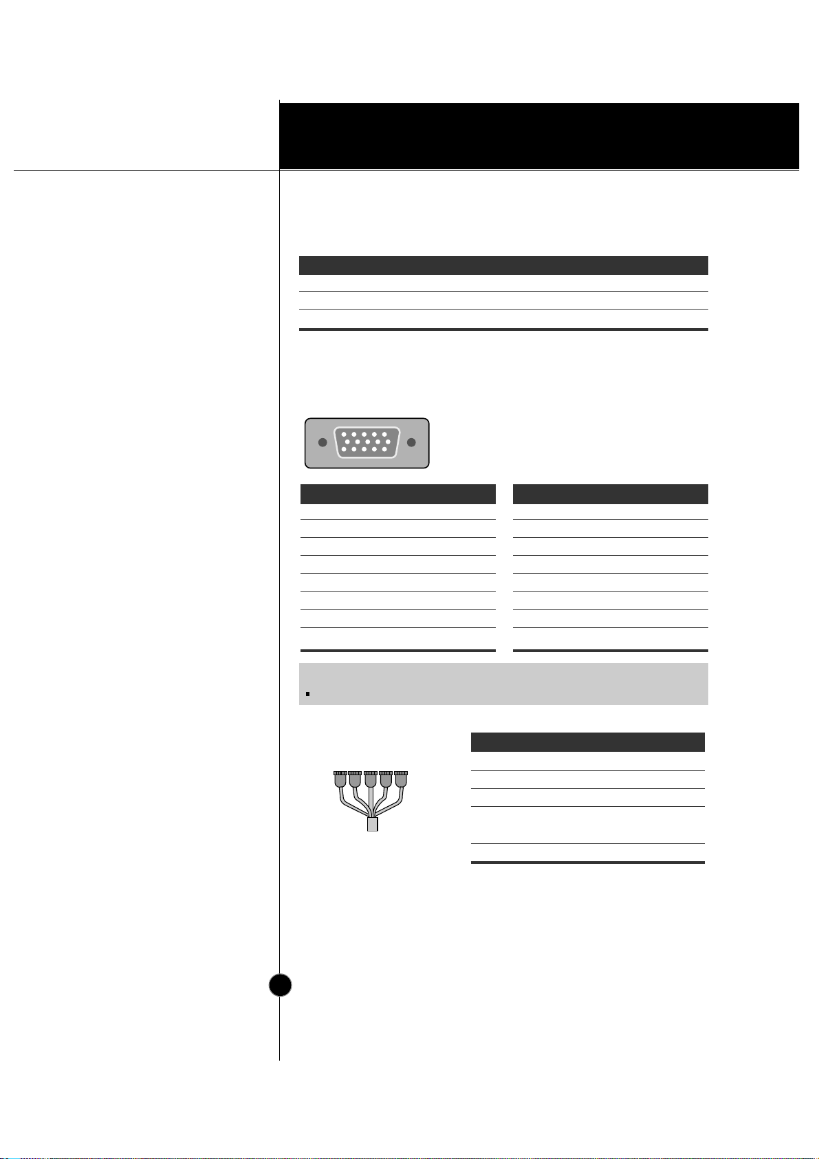
Pin Assignment
Specifications
15pin VGA Connector
5 BNC Connector
Priority Type H.Sync.
1
2
3
Separate Sync.
Composite Sync.
Sync. On Green
H. Sync.
H/V. Sync.
N.C.
V. Sync.
N.C.
N.C.
Pin Signal(D-Sub)
1
2
3
4
5
6
7
8
Red
Green
Blue
Ground
Self-Test
Red Ground
Green Ground
Blue Ground
Pin Signal(5 BNC) Color
1
2
3
4
5
Pin Signal(D-Sub)
9
10
11
12
13
14
15
NC
Ground
Ground
SDA
H. Sync.
V. Sync.
SCL
11
6
15
15
10
(N.C : No Connection)
NOTE
No. 5 Pin have to ground on the PC side.
12345
Red
Green
Blue
Gray
Black
Red
Green
Blue
H. Sync
(H or H+V)
V.sync
Page 27
A23
Technical Information
Picture T ube
Sync Input
Video Input
Dimensions
(with tilt/swivel stand)
Power Input
Weight
Environmental Conditions
Specifications
19 inch (18.0 inches viewable) Perfect Flat Tube
90 degree deflection
0.24mm Slot pitch
W-ARAS(Wide Anti-Reflective Anti-Static) coating
Horizontal Freq. 30 - 107kHz (Automatic)
Vertical Freq. 50 - 200Hz (Automatic)
Input Form Separate TTL, Positive/Negative
Composite TTL, Positive/Negative
SOG (Sync On Green)
Signal Input 15 pin D-Sub Connector / 5 BNC Connector
Input Form Separate, RGB Analog, 0.7Vp-p/75 ohm, Positive
Resolution(max) 1600 x 1200
@
85Hz
Width 47.0 cm / 18.5 inches
Height 40.9 cm / 16.1 inches
Depth 47.0 cm / 18.5 inches
AC 100-120/200-240V 50/60Hz 2.5/1.2A
Net 26.5 kg (58.4 lbs)
Operating Condition
Temperature 10 ˚C to 35 ˚C
Humidity 10 % to 90 % non-Condensing
Storage Condition
Temperature 0˚C to 60˚ C
Humidity 5 % to 90 % non-Condensing
NOTE
Information in this document is subject to change without notice and does
not represent a commitment on the part of LG Electronics Inc.
Page 28
Operation
FCC Compliance Statement
Canadian DOC Notice
CE Conformity Notice
Appendix
Communications Regulation Information
This equipment has been tested and found to comply within the limits of a
Class B digital device pursuant to Part 15 of the FCC Rules. These limits
are designed to provide reasonable protection against harmful interference
in a residential installation.
This equipment generates, uses, and can radiate radio frequency energy
and if not installed and used in accordance with the instructions, may
cause harmful interference to radio communications. However, there is no
guarantee that interference will not occur in a particular installation.
If this equipment does cause harmful interference to radio or television
reception (which can be determined by turning the equipment on and off),
the user is encouraged to try to correct the interference by using one or
more of the following measures:
Reorient or relocate the receiving antenna.
Increase the separation between the equipment and the receiver.
Connect the equipment into an outlet on a circuit different from that to
which the receiver is connected.
Consult the dealer or an experienced radio/TV technician for help.
Caution:
Changes or modifications not expressly approved by the party
responsible for compliance could void the user's (or your) authority to
operate the equipment. Only peripherals (digital input/output devices,
terminals, printers, etc.) certified to comply with the Class B limits may be
attached to this monitor. Operation with non-certified peripherals is likely
to result in interference to radio and TV reception.
Only shielded signal cables may be used with this System.
This Class B digital apparatus meets all requirements of the Canadian
Interference-Causing Equipment Regulations.
Cet appareil numérique de la classe B respecte toutes les exigences du
Règlement sur le matériel brouilleur du Canada.
Products with the "CE" Marking comply with the EMC
Directive(89/336/EEC) and LOW VOLTAGE Directive (73/23/EEC) issued
by the Commission of the European Community.
Compiance with these directives implies conformity to the following
European Norms :
• EN 55022 ; Radio Frequency Interference
• EN 50082-1:1992 ; Electromagnetic Immunity
• EN 60555-2 ; Power Line Harmonics
• EN 60555-3 ; Voltage Fluctuations
• EN 60950 ; Product Safety
APPENDIX
Page 29

Appendix
Congratulations!
Why do we have
environmentally labelled
computers?
Environmental Labelling of Personal Computers
You have just purchased a TCO’99 approved and labelled product! Your
choice has provided you with a product developed for professional use.
Your purchase has also contributed to reducing the burden on the
environment and also to the further development of environmentally
adapted electronics products.
This product meets the requirements for the TCO’99 scheme which
provides for an international environmental and quality labelling of personal
computers. The labelling scheme was developed as a joint effort by the
TCO (The Swedish Confederation of Professional Employees), Svenska
Naturskyddsforeningen (The Swedish Society for Nature Conservation),
Statens Energimyndighet (The Swedish National Energy Administration)
and SEMKO AB.
The requirements cover a wide range of issues: environment,
ergonomics, usability, reduction of electric and magnetic fields, energy
consumption and electrical safety.
In many countries, environmental labelling has become an established
method for encouraging the adaptation of goods and services to the
environment. The main problem, as far as computers and other
electronics equipment are concerned, is that environmentally harmful
substances are used both in the products and during their manufacture.
Since it is not so far possible to satisfactorily recycle the majority of
electronics equipment, most of these potentially damaging substances
sooner or later enter nature.
There are also other characteristics of a computer, such as energy
consumption levels, that are important from the viewpoints of both the
work (internal) and natural (external) environments. Since all methods of
electricity generation have a negative effect on the environment (e.g.
acidic and climate-influencing emissions, radioactive waste), it is vital to
save energy. Electronics equipment in offices is often left running
continuously and thereby consumes a lot of energy.
Page 30

Operation
What does labelling
involve?
Environmental
requirements
Appendix
Environmental Labelling of Personal Computers
The environmental demands impose restrictions on the presence and use
of heavy metals, brominated and chlorinated flame retardants, CFCs
(freons) and chlorinated solvents, among other things. The product must
be prepared for recycling and the manufacturer is obliged to have an
environmental policy which must be adhered to in each country where the
company implements its operational policy.
The energy requirements include a demand that the computer and/or
display, after a certain period of inactivity, shall reduce its power
consumption to a lower level in one or more stages. The length of time to
reactivate the computer shall be reasonable for the user.
Labelled products must meet strict environmental demands, for example,
in respect of the reduction of electric and magnetic fields, physical and
visual ergonomics and good usability.
Below you will find a brief summary of the environmental requirements
met by this product. The complete environmental criteria document may
be ordered from:
TCO Development
SE-114 94 Stockholm, Sweden
Fax: +46 8 782 92 07
Email (Internet): [email protected]
Current information regarding TCO’99 approved and
labelled products may also be obtained via the Internet,
using the address: http://www.tco-info.com/
Flame retardants
Flame retardants are present in printed circuit boards, cables, wires,
casings and housings. Their purpose is to prevent, or at least to delay the
spread of fire. Up to 30% of the plastic in a computer casing can consist
of flame retardant substances. Most flame retardants contain bromine or
chloride, and those flame retardants are chemically related to another
group of environmental toxins, PCBs. Both the flame retardants containing
bromine or chloride and the PCBs are suspected of giving rise to severe
health effects, including reproductive damage in fish-eating birds and
mammals, due to the bio-accumulative* processes. Flame retardants
have been found in human blood and researchers fear that disturbances in
foetus development may occur.
Page 31

OperationAppendix
Environmental Labelling of Personal Computers
The relevant TCO’99 demand requires that plastic components weighing
more than 25 grams must not contain flame retardants with organically
bound bromine or chlorine. Flame retardants are allowed in the printed
circuit boards since no substitutes are available.
Cadmium**
Cadmium is present in rechargeable batteries and in the colour-generating
layers of certain computer displays. Cadmium damages the nervous
system and is toxic in high doses. The relevant TCO’99 requirement
states that batteries, the colour-generating layers of display screens and
the electrical or electronics components must not contain any cadmium.
Mercury**
Mercury is sometimes found in batteries, relays and switches. It damages
the nervous system and is toxic in high doses. The relevant TCO’99
requirement states that batteries may not contain any mercury. It also
demands that mercury is not present in any of the electrical or electronics
components associated with the labelled unit. There is however one
exception. Mercury is, for the time being, permitted in the back light
system of flat panel monitors as there today is no commercially available
alternative. TCO aims on removing this exception when a mercury free
alternative is available.
CFCs (freons)
The relevant TCO’99 requirement states that neither CFCs nor HCFCs
may be used during the manufacture and assembly of the product. CFCs
(freons) are sometimes used for washing printed circuit boards. CFCs
break down ozone and thereby damage the ozone layer in the
stratosphere, causing increased reception on earth of ultraviolet light with
e.g. increased risks of skin cancer (malignant melanoma) as a
consequence.
Lead**
Lead can be found in picture tubes, display screens, solders and
capacitors. Lead damages the nervous system and in higher doses,
causes lead poisoning. The relevant TCO’99 requirement permits the
inclusion of lead since no replacement has yet been developed.
* Bio-accumulative is defined as substances which accumulate within living organisms
** Lead, Cadmium and Mercury are heavy metals which are Bio-accumulative.
Page 32

P/NO : 3828TUL
Printed in Korea
http://www.lge.co.kr
 Loading...