

LG FB790G-UL Service manual
COLOR MONIT OR
SER VICE MANUAL
Website:http://biz.LGservice.com
E-mail:http://www.LGEservice.com/techsup.html
CAUTION
BEFORE SERVICING THE UNIT,
READ THE SAFETY PRECAUTIONS IN THIS MANUAL.
MODEL: F700P (FB790G-UL)
CHASSIS NO. : CA-1 14
F ACTORY MODEL: FB790G
*( ) ID LABEL Model No.
1. PICTURE TUBE
Size : 17 inch (Flat Slot Mask)
DefIection Angle : 90°
Neck Diameter : 29.1 mm
Phosphor : P22
Slot Pitch : 0.24 mm
Face Treatment : W-ARASC (Anti-Reflective and
Anti-Static Coating),
Internal Anti-Glare
2. SIGNAL
2-1. Horizontal & Vertical Sync
1) Input Voltage Level: Low= ≤0.8V, High= ≥2.1V
2) Sync Polarity : Positive or Negative
2-2. Video Input Signal
1) Voltage Level : 0~0.7 Vp-p
a) Color 0, 0 : 0 Vp-p
b) Color 7, 0 : 0.467 Vp-p
c) Color 15, 0 : 0.7 Vp-p
2) Input Impedance : 75 Ω
3) Video Color : R, G, B Analog
4) Signal Format : Refer to the Timing Chart
2-3. Signal Connector
15 Pin D-Sub Connector
2-4. Scanning Frequency
Horizontal : 30~96 kHz
Vertical : 50~160 Hz
3. POWER SUPPLY
AC 100~240V, 50/60HZ, 2.5A Max
AC 200~240V, 50Hz, 1.5A Max.(PFC version)
3-2. Power Consumption
4. DISPLAY AREA
4-1. Active Video Area :
• Max Image Size - 325.4 x 244.1mm (12.91" x 9.61")
• Preset Image Size - 310 x 230 mm (12.20" x 9.06")
4-2. Display Color : Full Colors
4-3. Display Resolution : 1600 Dots x 1200Lines
4-4. Video Bandwidth : 203MHz
5. ENVIRONMENT
5-1. Operating Temperature: 0°C~40°C (32°F~103°F)
(Ambient)
5-2. Relative Humidity : 10%~90%
(Non-condensing)
5-3. Altitude : 10,000 ft
6. DIMENSIONS (with TILT/SWIVEL)
Width : 415.0 mm (16.34")
Depth : 432.0 mm (17.00")
Height : 413.0 mm (16.25")
7. WEIGHT (with TILT/SWIVEL)
Net Weight : 18 kg (39.68 lbs)
Gross Weight : 20.5 kg (45.20 lbs)
8. USB Specifications
USB Standard :
Rev. 1.0 complied self-powered hub
Downstream power supply
: 500mA for each (MAX)
Communication speed : 12 Mbps (Full), 1.5 Mbps (Low)
USB port : 1 Upstream port
4 Downstream ports
CONTENTS
SPECIFICATIONS
- 2 -
SPECIFICATIONS ................................................... 2
SAFETY PRECAUTIONS ........................................ 3
TIMING CHART ....................................................... 4
OPERATING INSTRUCTIONS ................................ 5
CONTROL LOCATIONS ......................................... 7
WIRING DIAGRAM ................................................. 8
DISASSEMBLY ....................................................... 9
BLOCK DIAGRAM ................................................. 10
DESCRIPTION OF BLOCK DIAGRAM................... 11
ADJUSTMENT ...................................................... 13
TROUBLESHOOTING GUIDE .............................. 15
EXPLODED VIEW.................................................. 22
REPLACEMENT PARTS LIST .............................. 24
PIN CONFIGURATION .......................................... 31
SCHEMATIC DIAGRAM......................................... 32
PRINTED CIRCUIT BOARD................................... 34
MODE
MAX
NORMAL (ON)
STAND-BY
SUSPEND
OFF
H/V SYNC
ON/ON
OFF/ON
ON/OFF
OFF/OFF
POWER CONSUMPTION (USB)
less than 110W (130W)
less than 83W (104W)
less than 8W (30W)
less than 8W (30W)
less than 1W (20W)
LED COLOR
GREEN
GREEN
ORANGE
ORANGE
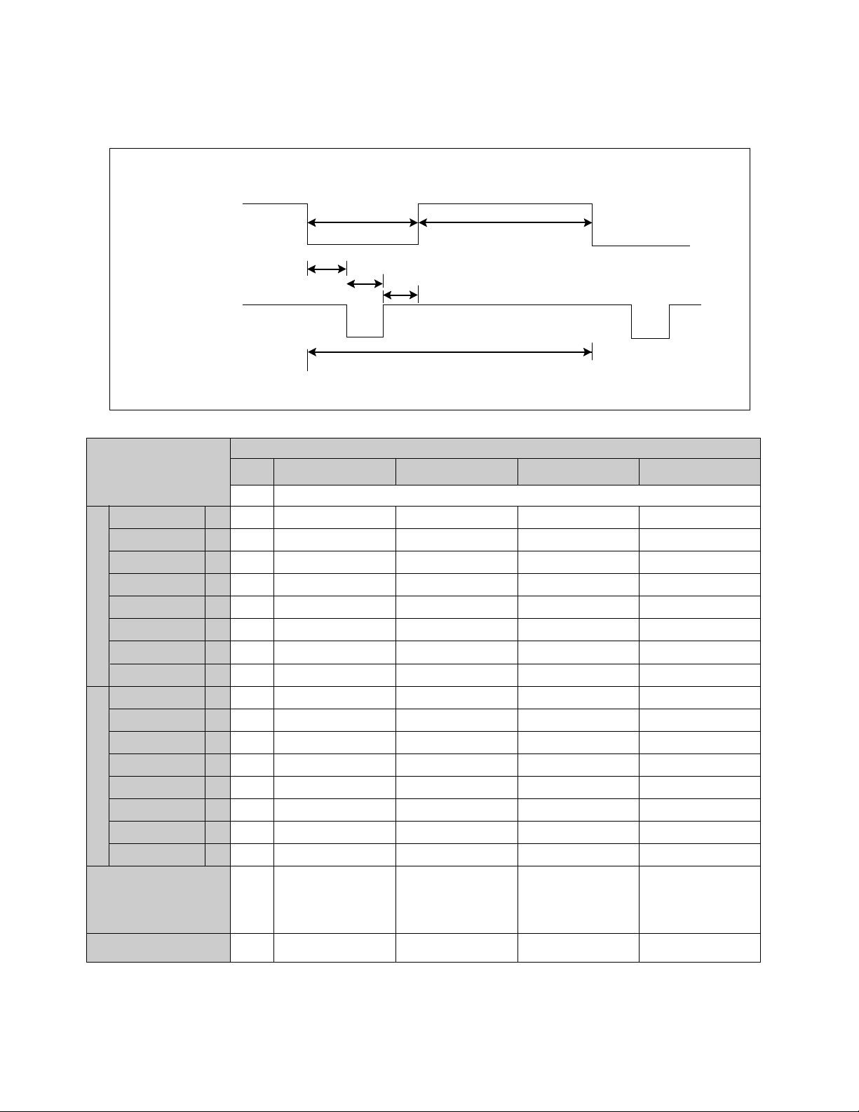
TIMING CHART
- 4 -
VIDEO
SYNC
D
A
E
F
BC
kHz
µs
µs
µs
µs
µs
µs
Hz
ms
ms
ms
ms
ms
ms
MODE 1
–
43.269
23.112
17.778
5.334
1.556
1.556
2.222
–
85.008
11.763
11.093
0.670
0.023
0.069
0.578
640
X
480
85Hz
Yes
MODE 2
+
53.674
18.631
14.222
4.409
0.569
1.138
2.702
+
85.061
11.756
11.178
0.578
0.019
0.056
0.503
800
X
600
85Hz
Yes
MODE 3
+
68.677
14.561
10.836
3.725
0.508
1.016
2.201
+
84.997
11.765
11.183
0.582
0.015
0.044
0.523
1024
X
768
85Hz
Yes
MODE 4
+
91.146
10.971
8.127
2.844
0.406
1.016
1.422
+
85.024
11.762
11.235
0.527
0.011
0.033
0.483
1280
X
1024
85Hz
Yes
MARK
A
B
C
D
E
F
A
B
C
D
E
F
MODE
FACTORY PRESET MODE
Resolution
Recall
H
O
R
I
Z
O
N
T
A
L
V
E
R
T
I
C
A
L
Sync Polarity
Frequency
Total Period
Video Active Time
Blanking Time
Front Porch
Sync Duration
Back Porch
Sync Polarity
Frequency
Total Period
Video Active Time
Blanking Time
Front Porch
Sync Duration
Back Porch
VESA
BLOCK DIAGRAM
- 10 -
SIGNAL
INPUT
SUB
TRANS
(T903)

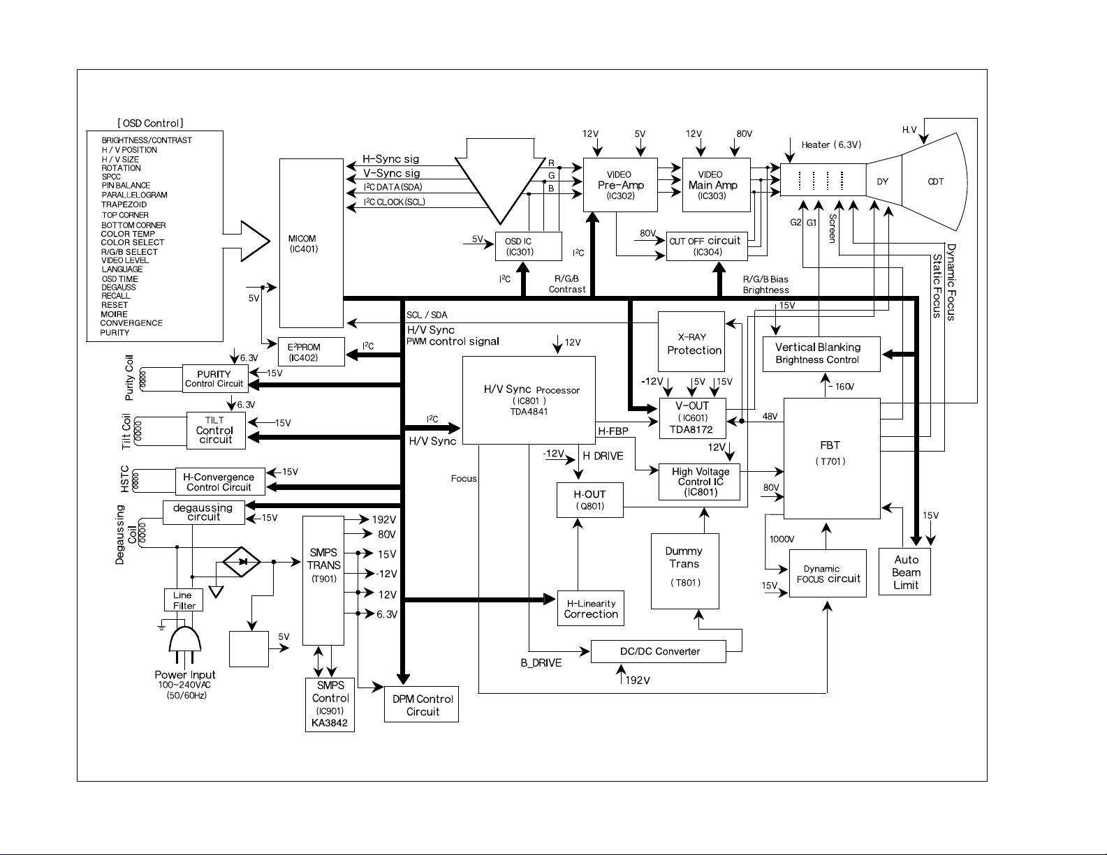
DESCRIPTION OF BLOCK DIAGRAM
- 11 -
1. Line Filter & Associated Circuit.
This is used for suppressing noise of power input line
flowing into the monitor and/or some noise generated
in this monitor flowing out through the power input
line.
That is to say, this circuit prevents interference
between the monitor and other electric appliances.
2. Degauss Circuit & Coil.
The degauss circuit consists of the degaussing coil,
the PTC (Positive Temperature Coefficient) thermistor
(TH901), and the relay (RL901). This circuit eliminates
abnormal color of the screen automatically by
degaussing the slot mask in the CDT when turn on the
power switch.
When you need to degauss while using the monitor,
select DEGAUSS on the OSD menu.
3. SMPS (Switching Mode Power Supply).
This circuit works with power of 100~240V or
200~240V (50/60Hz) specially for PFC version.
The operation procedure is as follows:
1) AC input voltage is rectified and smoothed by
the bridge diode (D901) and the capacitor (C905).
2) The rectified voltage (DC voltage) is applied to the
primary coil of the transformer (T901).
3) The control IC (IC901) generates switching pulse
to turn on and off the primary coil of the
transformer (T901) repeatedly.
4) Depending on the turn ratio of the transformer, the
secondary voltages appear at the secondary coil of
the transformer (T901).
5) These secondary voltages are rectified by each
diode (D924, D926, D923, D922, D921, D920) and
operate the other circuits. (Deflection, Video
Amplifier, etc.)
4. Display Power Management Circuit.
This circuit control power consumption of the monitor
by detecting H and V sync signal. There are stand-by
and suspend mode. When no horizontal or vertical
sync signal input, the circuit consists of Q913, Q915
and IC401 control signal becomes stand-by and
suspend mode. It’s power consumption is below 8W.
When no horizontal and vertical sync signal input, it’s
power consumption is below 1W.
5. X-ray Protection.
This circuit detects the rectified DC voltage comes
from the FBT pin 4. If the high voltage of the FBT
reaches up to about 30kV (abnormal state), H.V
control (IC802) detects. It stops B+voltage supplied to
the FBT (T701), and high voltage is not be generated,
(In the normal state, the high voltage is about 26kV.)
6. Micom(Microprocessor) Circuit.
The operating procedure of Micom (Microprocessor)
and its associated circuit is as follows:
1) H and V sync signal is supplied from Signal Cable t o t he
Micom (IC401).
2) The Micom (IC401) distinguishes polarity and
frequency of H and V sync.
3) The Micom controls each OSD function signals.
(H-size, H-position, V-size, etc.)
4) The controlled data of each mode is stored in IC402.
User can adjust screen condition by each OSD
function. The data of the adjust screen condition is
stored automatically.
7. Horizontal and Vertical Synchronous Processor.
This circuit generates the horizontal drive pulse and
the vertical drive pulse by taking sync-signal from
Signal Cable. This circuit consists of the
TDA4841(IC801) and the associated circuit.
8. Oscillating Circuit for D/D Converter.
This circuit generates the pulse wave which has the
horizontal period by taking the output of the
TDA4841(IC801).
9. D/D (DC to DC) Converter.
This circuit supplies DC voltage to the horizontal
deflection output circuit by decreasing DC 192V which
is the secondary voltage of the SMPS in accordance
with the input horizontal sync signal.
10. D/D Drive & Convert Circuit.
This circuit is used for supplying B+voltage to
horizontal deflection output transistor (Q801).
11. Horizontal Deflection Output Circuit.
This circuit makes the horizontal deflection by
supplying the saw-tooth current to the horizontal
deflection yoke.

- 12 -
12. High Voltage Output & FBT (Flyback Transformer).
The high voltage output circuit is used for generating
pulse wave to the primary coil of the FBT (Flyback
Transformer (T701)). A boosted voltage (about 26kV)
appears at the secondary of the FBT and it is supplied
to the anode of the CDT.
And there are another output voltages such as the
dynamic focus voltage.
13. H-Linearity Correction Circuit.
This circuit corrects the horizontal linearity for each
horizontal sync frequency.
14. Vertical Output Circuit.
This circuit takes the vertical wave from the
TDA4841(IC801) and performs the vertical deflection
by supplying the saw-tooth wave current from the
TDA8172 (IC601) to the vertical deflection yoke.
15. Dynamic Focus Output Circuit.
This circuit takes H and V parabola wave from the
TDA4841(IC801), and amplifies these waves to offer
to the FBT (T701).
16. H & V Blanking and Brightness Control.
This circuit eliminates the retrace line by supplying a
negative pulse to the G1 of the CDT.
17. Image Rotation (Tilt) Circuit.
This circuit corrects the tilt of the screen by supplying
the image rotation signal to the tilt coil which is
attached to the CDT near the deflection.
18. Static Convergence Control Circuit.
This circuit corrects the convergence of the screen by
supplying the convergence signal to the 4H (STC) coil
which is attached to the CDT near the deflection.
19. Moire Reduction Circuit
This circuit reduce interference between the periodical
display pattern and the CDT's slot (or dot).
The positions of every other one dot video signal
beams (red, green, and blue beam) are shifted finely,
thus reducing interference.
20. OSD Circuit.
This circuit is used for performing the OSD (OnScreen- Display) function.
When a user selects the OSD Select/Adjustment
control, the adjustment status displays on the screen.
21. Video Pre-Amp Circuit.
This circuit amplifies the analog video signal from 0-
0.7V to 0-4V. This circuit is operated by taking the
clamp, R, G, B drives, and contrast signals from the
Micom (IC401).
22. Video Output Amp Circuit.
This circuit amplifies the video signal which comes
from the video pre-amp circuit and amplified video
signal is applied to the CDT cathode.

ADJUSTMENT
- 13 -
GENERAL INFORMATION
All adjustment are thoroughly checked and corrected
when the monitor leaves the factory, but sometimes
several adjustments may be required.
Adjustment should be following procedure and after
warming up for a minimum of 30 minutes.
• Alignment appliances and tools.
- IBM compatible PC.
- Programmable Signal Generator.
(eg. VG-819 made by Astrodesign Co.)
- EPROM or EEPROM with saved each mode data.
- Alignment Adaptor and Software.
- Digital Voltmeter.
- White Balance Meter.
- Luminance Meter.
- High-voltage Meter.
AUTOMATIC AND MANUAL DEGAUSSING
The degaussing coil is mounted around the CDT so that
automatic degaussing when turn on the monitor. But a
monitor is moved or faced in a different direction, become
poor color purity cause of CDT magnetized, then press
DEGAUSSING on the OSD menu.
ADJUSTMENT PROCEDURE & METHOD
-Install the cable for adjustment such as Figure 1and run
the alignment program on the DOS for IBM compatible PC.
-Set external Brightness and Contrast volume to max position.
1. Adjustment for B+ Voltage.
1) Display cross hatch pattern at Mode 4.
2) Adjust C921 (+) voltage to 192V ± 0.2V with VR901.
2. Adjustment for High-Voltage.
1) Display cross hatch pattern at Mode 4.
2) Adjust CDT Anode voltage to 26kV ± 0.2kV with
VR801.
3. Adjustment for Horizontal Raster Center.
1) Display cross hatch pattern at Mode 4.
2) Adjust the Back Raster should be center of the
screen with SW801.
4. Adjustment for Factory Mode (Preset Mode).
1) Display cross hatch pattern at Mode 1~4.
2) Run alignment program for FB790G on the IBM
compatible PC.
3) EEPROM → ALL CLEAR → Y(Yes) command.
<Caution> Do not run this procedure unless the
EEPROM is changed. All data in EEPROM (mode
data and color data) will be erased.
4) COMMAND → PRESET START → Y(Yes)
command.
5) DIST. ADJ. → FOS. ADJ command.
6) Adjust H-POSITION as arrow keys to center of the
screen.
7) Adjust H-SIZE as arrow keys to 310 ± 2mm.
8) Adjust V-POSITION as arrow keys to center of the
screen.
9) Adjust V-SIZE as arrow keys to 230 ± 2mm.
10) Adjust TRAPEZOID as arrow keys to be the best
condition.
11) Adjust TILT as arrow keys to be the best condition.
12) Display cross hatch pattern at Mode 4.
13) DIST. ADJ. → BALANCE DATA command.
14) Adjust balance of Pin-Balance as arrow keys to be
the best condition.
15) Adjust parallelogram as arrow keys to be the best
condition.
16) Save of the Mode.
17) Save of the System.
18) Display from Mode 4 and repeat above from
number 6) to 15).
19) COMMAND → PRESET EXIT → Y (Yes) command.
5. Adjustment for White Balance and Luminance.
1) Set the White Balance Meter.
2) Press the DEGAUSSING on the OSD menu for
demagnetization of the CDT.
3) Display color 0,0 pattern at Mode 4.
4) COMMAND → PRESET START → Y(Yes)
command.
5) Set Bightness and Contrast to max position.
6) COLOR ADJ. → LUMINANCE command of the
alignment program.
7) COLOR ADJ. → BIAS ADJ. command of the
alignment program.
8) Check whether blue color or not at R-BIAS and GBIAS to min position, Sub-Brightness to 90 position,
B-BIAS to 75 position. If it's not blue color, the
monitor must repair.
9) Adjust Screen control on the FBT to 0.15 ± 0.02FL
of the raster luminance.
10)Adjust R-BIAS and G-BIAS command to x=0.283 ±
0.006 and y=0.298 ± 0.006 on the White Balance
Meter with PC arrow keys.

- 14 -
11) Display color 15,0 box pattern(70x70mm) at mode 4.
12)DRIVE ADJ command.
13) Set B-DRIVE to 100 at DRIVE of the alignment
program.
14) Adjust R-DRIVE and G-DRIVE command to white
balance x=0.283 ± 0.003 and y=0.298 ± 0.003 on
the White Balance Meter with PC arrow keys.
15) Adjust SUB-CONTRAST command to 47±1FL of
the raster luminance.
15)Display color 15,0 full white patten at Mode 4.
16)COLOR ADJ. → LUMINANCE → ABL command.
17) Adjust ABL to 32 ± 1FL of the luminance.
18) Exit from the program.
6. Adjustment for Focus.
1)
Display H character in full screen at Mode 4.
2)
Adjust two Focus control on the FBT that focus
should be the best condition.
 Loading...