

Page 1

website : http://biz.lgservice.com
e-mail : http://LGEservice.com/techsup.html
WASHING MACHINE
SERVICE MANUAL
CAUTION
READ THIS MANUAL CAREFULLY TO DIAGNOSE PROBLEMS
CORRECTLY BEFORE OFFERING SERVICE.
BEFORE SERVICING THE WASHING MACHINE, UNPLUG THE POWER
CORD TO AVOID THE RISK OF AN ELECTRIC SHOCK.
WHEN SERVICING INTERNAL PARTS ,
USE ONL
AFTER SERVICING THE ELECTRIC WIRE, INSURE THAT INSULATION
Y SE RVICE PARTS SUPPLIED FROM LG.
TAPE IS APPLIED TO PREVENT AN ELECTRICAL SHORT.
MODEL :
F*V7*CP(0~9)
Page 2

CONTENTS
SPECIFICATIONS ............................................................................................................................. 3
1.
2. FEATURES & TECHNICAL EXPLANATION ..................................................................................... 4
3. PARTS IDENTIFICATION ................................................................................................................. 6
4. INSTALLATION.................................................................................................................................. 7
5. OPERATION ...................................................................................................................................12
6. WIRING DIAGRAM / PCB LAYOUT ................................................................................................17
7. TROUBLESHOOTING......................................................................................................................19
7-1.BEFORE PERFORMING SERVICE .........................................................................................19
7-2.LOAD TEST MODE .................................................................................................................. 19
7-3.HOW TO CHECK THE WATER LEVEL FREQUENCY ............................................................ 20
7-4.ERROR DISPLAY ..................................................................................................................... 21
7-5.TROUBLESHOOTING WITH ERROR .....................................................................................23
• IE (Water Inlet Error) .............................................................................................................. 24
• UE (Unbalanced Error) ........................................................................................................... 25
• OE (Water Outlet Error) .......................................................................................................... 26
• FE (Over Flow Error) .............................................................................................................. 28
• PE (Pressure Sensor S/W Error) ............................................................................................ 29
• dE2 (Door open Error) .............................................................................................................. 31
• dE1 (Door switch Error) .............................................................................................................. 31
• tE (Thermistor (Heating) Error) ............................................................................................... 33
• LE (Motor Lock Error) ............................................................................................................. 36
8. TROUBLESHOOTING WITHOUT ERROR CODES ...................................................................... 38
• Power Failure or no power .................................................................................................... 38
• Vibration & Noise during spin ................................................................................................. 39
• Detergent & Softener does not flow in .................................................................................... 40
• Water Leak ............................................................................................................................. 41
• Before using the Tag On function .......................................................................................... 43
9. PART INSPECTION ........................................................................................................................ 45
9-1.FILTER ASSEMBLY (LINE FILTER) ......................................................................................... 45
9-2.DOOR LOCK SWITCH ASSEMBLY ......................................................................................... 46
9-3.STATOR ASSEMBLY ............................................................................................................... 48
10. DISASSEMBLY INSTRUCTIONS .................................................................................................. 49
11. EXPLODED VIEW AND PART LIST .............................................................................................. 57
Page 3
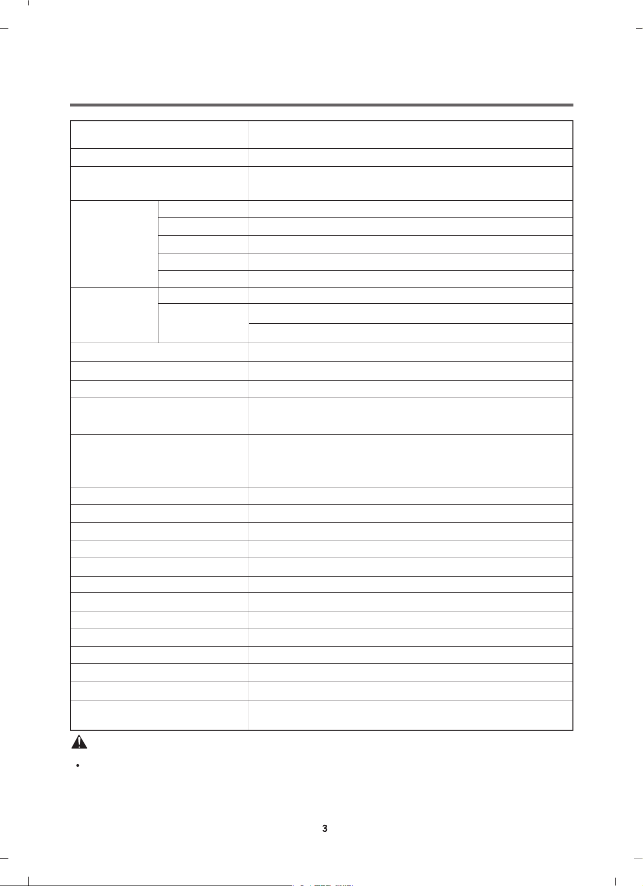
1. SPECIFICATION
ITEM
POWER SUPPLY
PRODUCT WEIGHT
WASHING
SPIN
ELECTRICITY
CONSUMPTION
REVOLUTION
SPEED
OPERATION WATER PRESSURE
CONTROL TYPE
WASH & DRY CAPACITY
DRAIN MOTOR
WASH HEATER
DRY HEATER 1350 W
WASH
SPIN
DIMENSION
Refer to 1 page
220 V - 240 V ~,50Hz/60Hz
73kg
155 W
490 W
20 W
2200 W
46 rpm
F4V******* : No Spin / 400 / 800 / 1000 / 1200 / 1400
F2V******* : No Spin / 400 / 800 / 1000 / 1100 / 1200
0.1 ~ 1.0 MPa (1.0 kgf / cm2~ 10.0 kgf / cm2)
Electronic
Refer to the Rating Label
600mm x 560mm x 850mm
WASH PROGRAM
RINSE
DOOR SWITCH TYPE
WATER LEVEL
RESERVATION
SENSING LAUNDRY AMOUNT
FUZZY LOGIC
DISPLAY REMAINING TIME
ERROR DIAGNOSIS
POWER AUTO OFF
CHILD LOCK
AUTO RESTART
TIME SAVE
SMART
Cotton , Cotton+, Turbo Wash 39, Mixed Fabric, Easy Care,
Steam Refresh
Speed 14, Wash+Dry, Tub Clean, Download Cycle
, Allergy Care, Delicate, Hand/Wool, Dry Only,
+
Rinse
PTC+Sol
by Pressure Sensor S/W
From 3 hours to 19 hours
Wi-fi (Smart ThinQ 3.0)
enoid
Adapted
Adapted
Adapted
13 items
Adapted
Adapted
Adapted
Adapted
WARNING
To reduce the risk of personal injury, adhere to all industry recommended safety procedures including
the use of long sleeved gloves and safety glasses.
Failure to follow all of the safety warnings in this
injury or death.
manual could result in property damage, personal
Page 4
2. FEATURES & TECHNICAL EXPLANATION
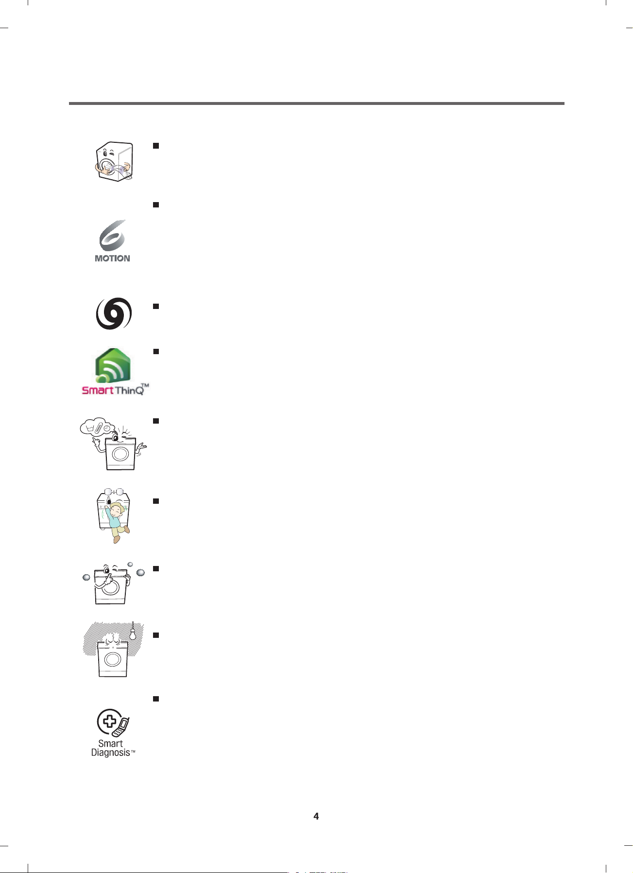
2-1.
Product Features
Inverter Direct Drive system
The advanced Brushless DC motor directly drives the drum without
belt and pulley.
6 Motion
Washer is able to perform various drum actions or a combination of
different actions depending on the wash program selected.
Combined with a controlled spin speed and the ability of the drum to
rotate both left and right, the wash performance of the machine is greatly
improved, giving you perfect results every time.
Turbo Wash
Wash the laundries in 1 hour with energy and water saving.
Smart ThinQ (Wi-Fi feature)
This feature lets you use various functions of the product, e.g., remote
control, smart alert, mode download, and smart self-diagnosis via the
smartphone app.
More economical with Intelligent Wash system
Intelligent Wash System detects the size of load and water temperature,
and then determines the optimum water level and washing time to
minimize energy and water consumption.
Child Lock
The Child Lock prevents children from pressing any button to change
the settings during operation.
Low noise speed control system
By sensing the amount of load and balance, it evenly distributes load
to minimize the spinning noise level.
Auto Restart
Auto Restart allows the program to restart all by itself in case of power
failure. It does from the stage where it stopped.
SmartDiagnosis™
Should you experience any technical difficulty with your washing
machine, it has the capability of transmitting data by phone to the
Customer Information Center. The call center agent records the data
transmitted from your machine and uses it to analyze the issue,
providing a fast and effective diagnosis.
Page 5
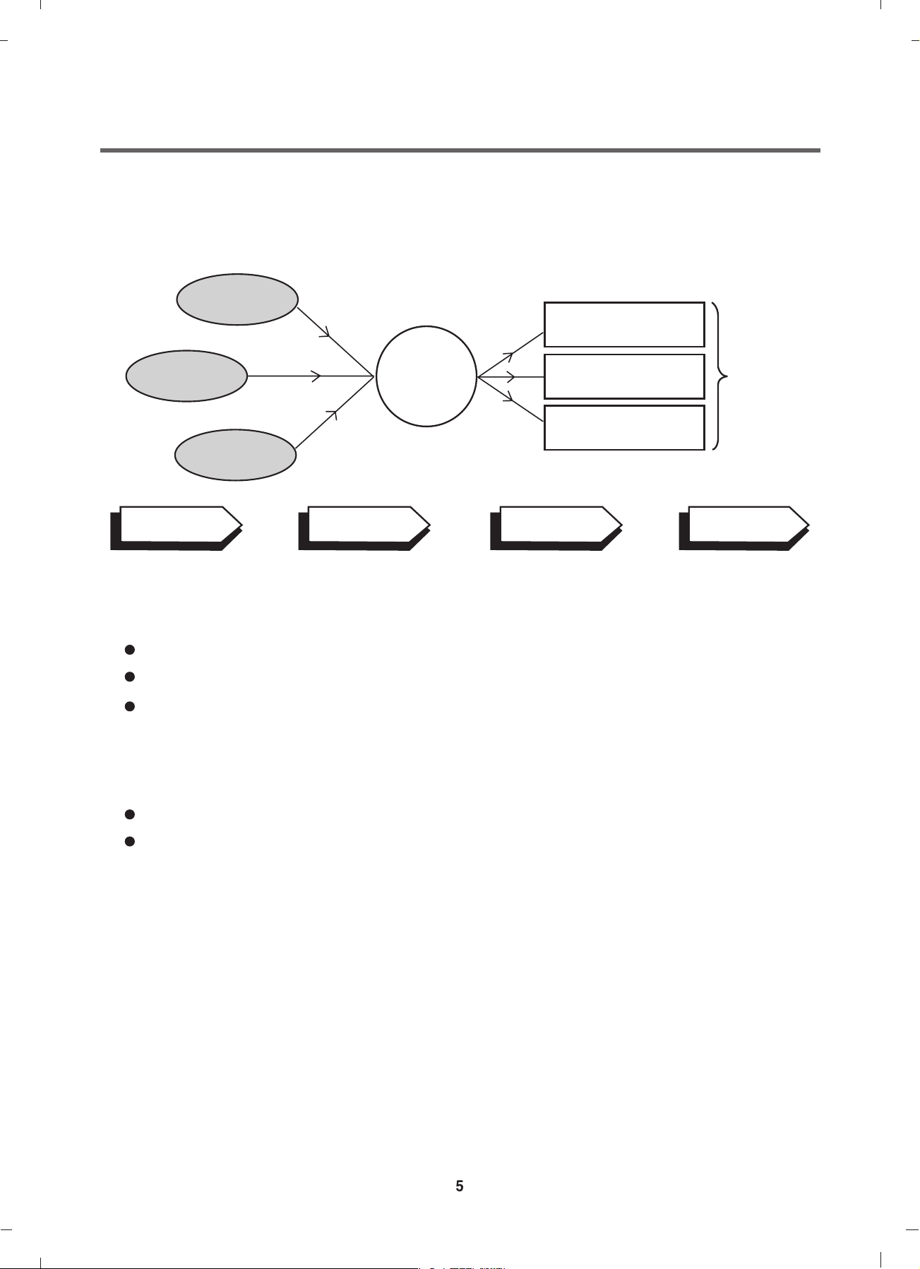
2-2. DETERMINE WASHING TIME BY FUZZY LOGIC
To get the best washing performance optimal time is determined by sensing the water
temperature, selected washing temperature and laundry amount.
water
temperature
washing time
selected
washing
temperature
SENSING
laundry
amount
PROCESSING
FUZZY
LOGIC
rinse time
spin rhythm, time
DET ERMINATION
the best
washing
performance
EFFECT
2-3. WATER LEVEL CONTROL
This model adopts a pressure sensor which can sense the water level in the tub.
Water supply is stopped when the water level reach the preset level, then washing program proceeds.
Spinning does not proceed until the water in the tub reduces to a certain level.
2-4. THE DOOR CAN NOT BE OPENED
While program is operating.
While Door Lock light is on.
Page 6
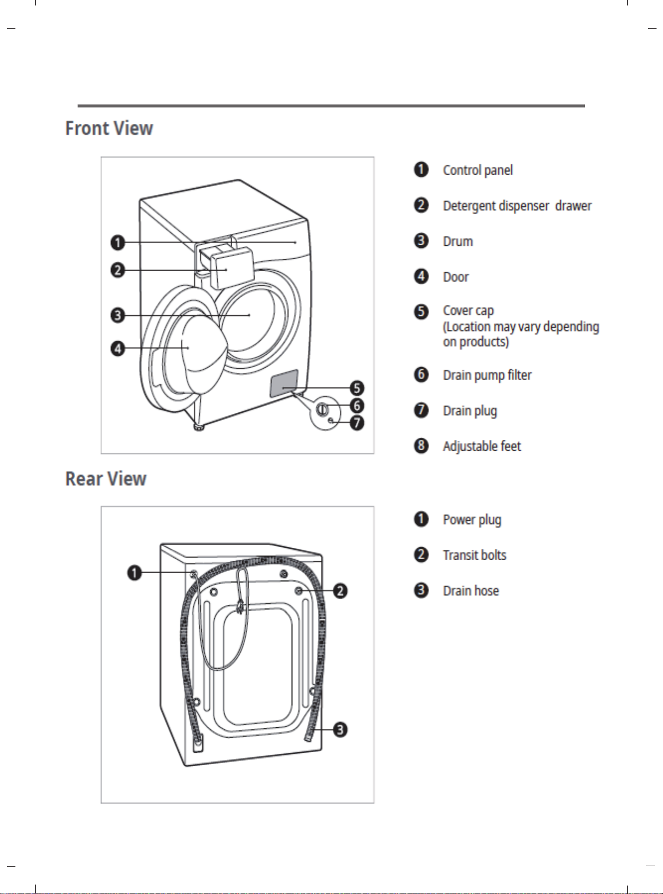
3. PARTS IDENTIFCATION
6
Page 7
3.PARTS IDENTIFCATION
7
Page 8
4. INSTALLATION
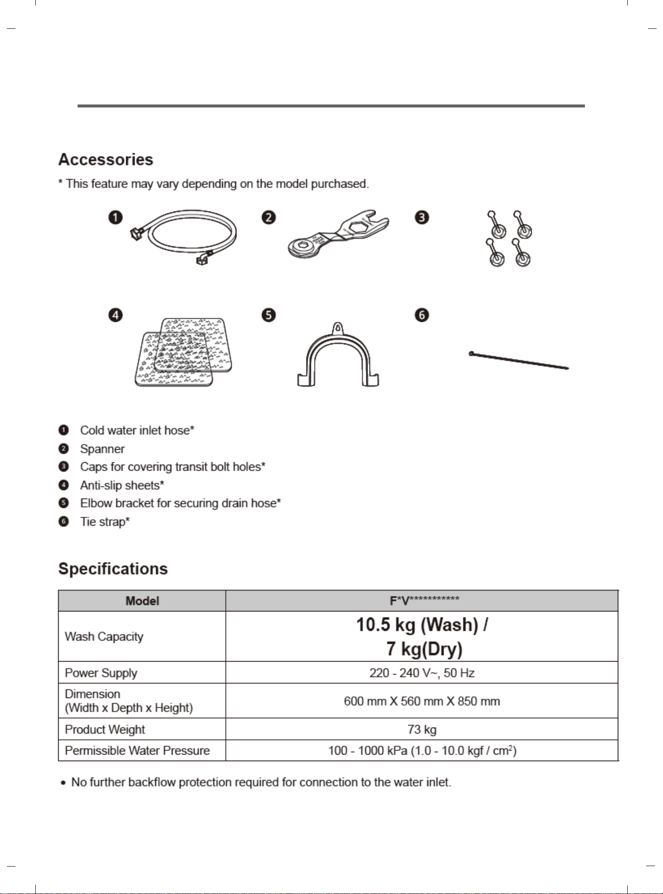
INSTALLATION
The appliance should be installed as follows.
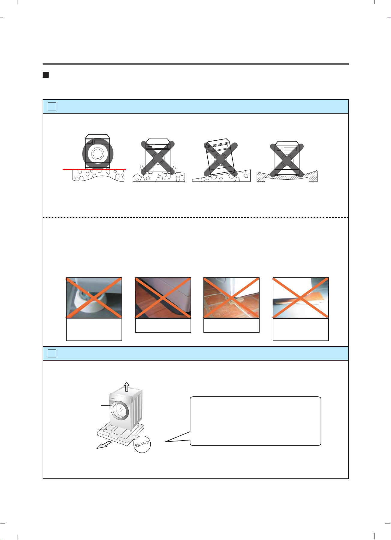
1
Check the conditions of installation area.
1. Check level ground.
horizontal
On raised foundations or upper level homes, the vibrations can be caused by the type of flooring.
It may be necessary to move the machine to a different area in the home or have the floor
reinforced to properly support the operation of the unit.
2. Check for humidity or any foreign objects under the feet.
Clean the floor, there should be no foreign objects under the feet.
If the unit has foreign objects underneath the feet, this will prevent the unit from being leveled properly
and will cause vibrations and slipping.
Remove any foreign objects, if any from underneath the machine and level unit properly.
See below for examples of foreign objects.
Purchased
stopper
2
Open the box and check appliance condition.
Washer
Carpet Paper Laminated
paper
This leveling (or spanner) wrench must
be used to remove the shipping bolts
Base Packing
and level the unit. This should be kept
for future use.
Spanner
8
Page 9
1. 2. 3.
1. 2. 3.
9
Page 10
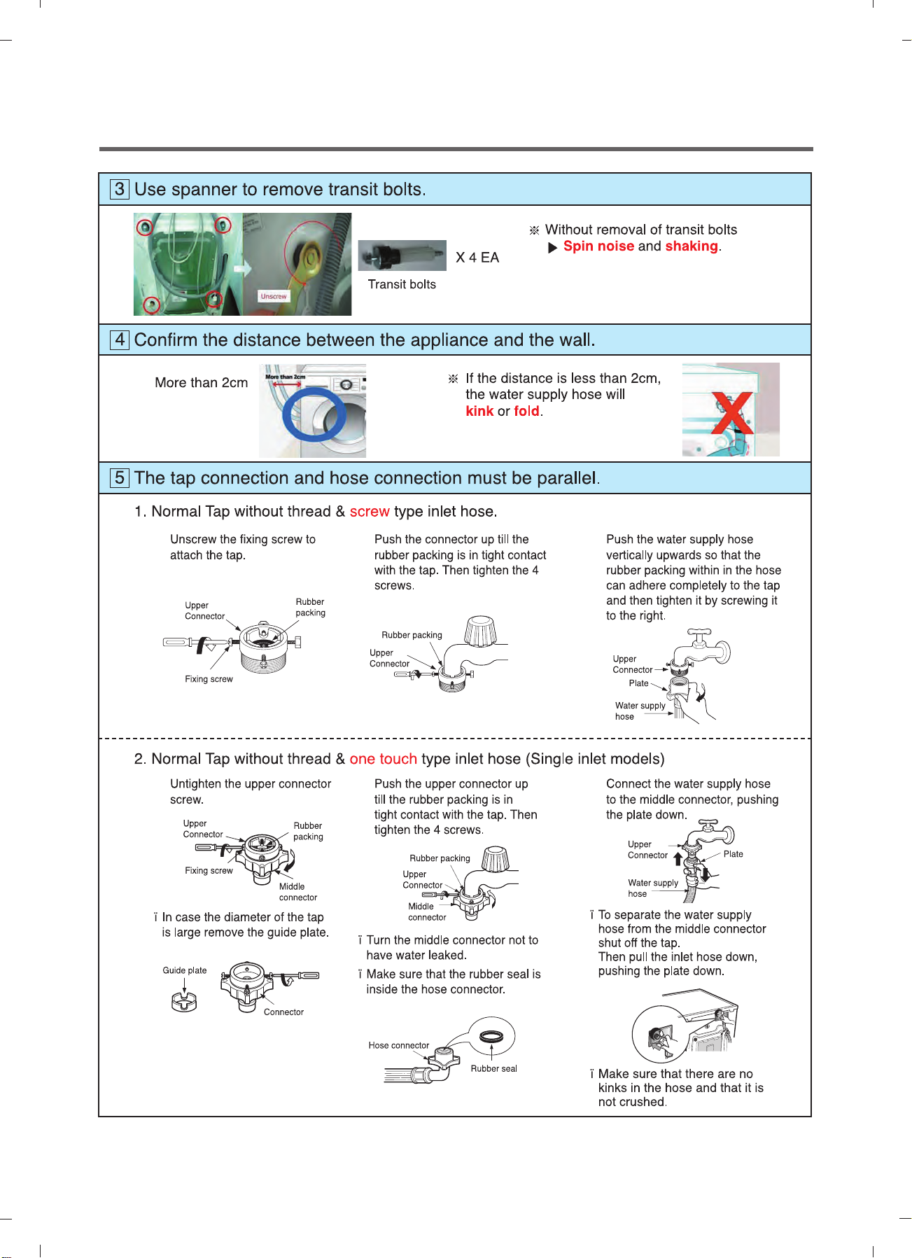
6
Connect Drain Hose.
If the drain hose is not installed properly, the unit will not drain properly.
This allows water to back flow into the unit which can cause odors.
Refer to Owner Manual for proper drain hose installation.
The odor could also be coming from the home’s drain to which the drain hose is attached.
Laundry tub
about 100 cm
about 145 cm
about 105 cm
max. 100 cm
min. 60 cm
Max. 100cm
min. 60cm
Hose
Retainer
Tie
strap
Max. 100cm
min. 60cm
In this type of drain hose installation, the odor could be coming from the standpipe.
This odor can come up the drain hose and into the unit.
Pour a cup or two of bleach or vinegar down the home drain
and let it sit for 24 hours before running another cycle.
This will help eliminate odor from the home drain.
If a cycle is started too soon after doing this, it will not help the issue.
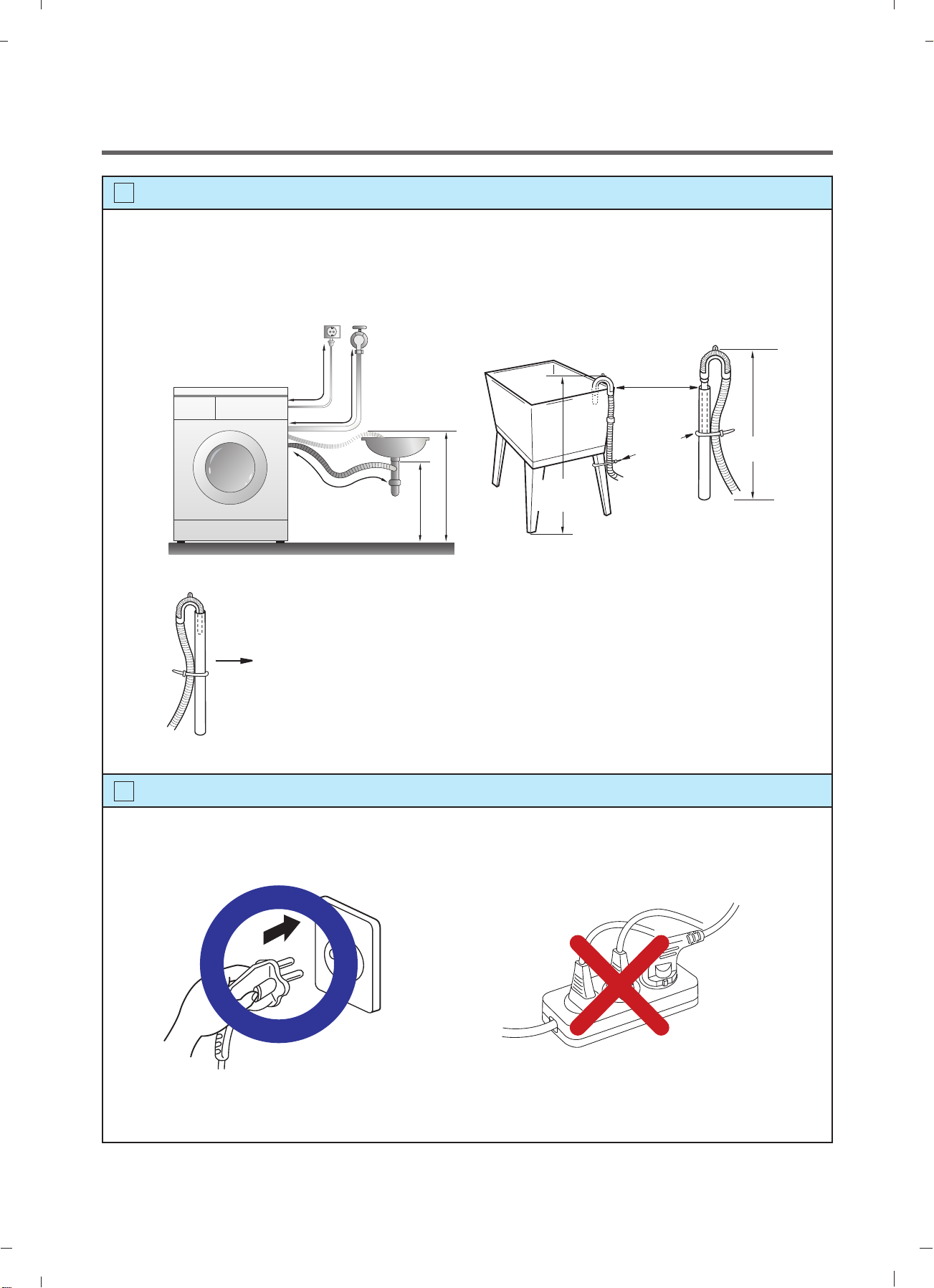
7
Connect power plug.
Connect the power plug to the wall outlet. Avoid connecting several electric devices,
it may be the cause of a fire.
10
Page 11
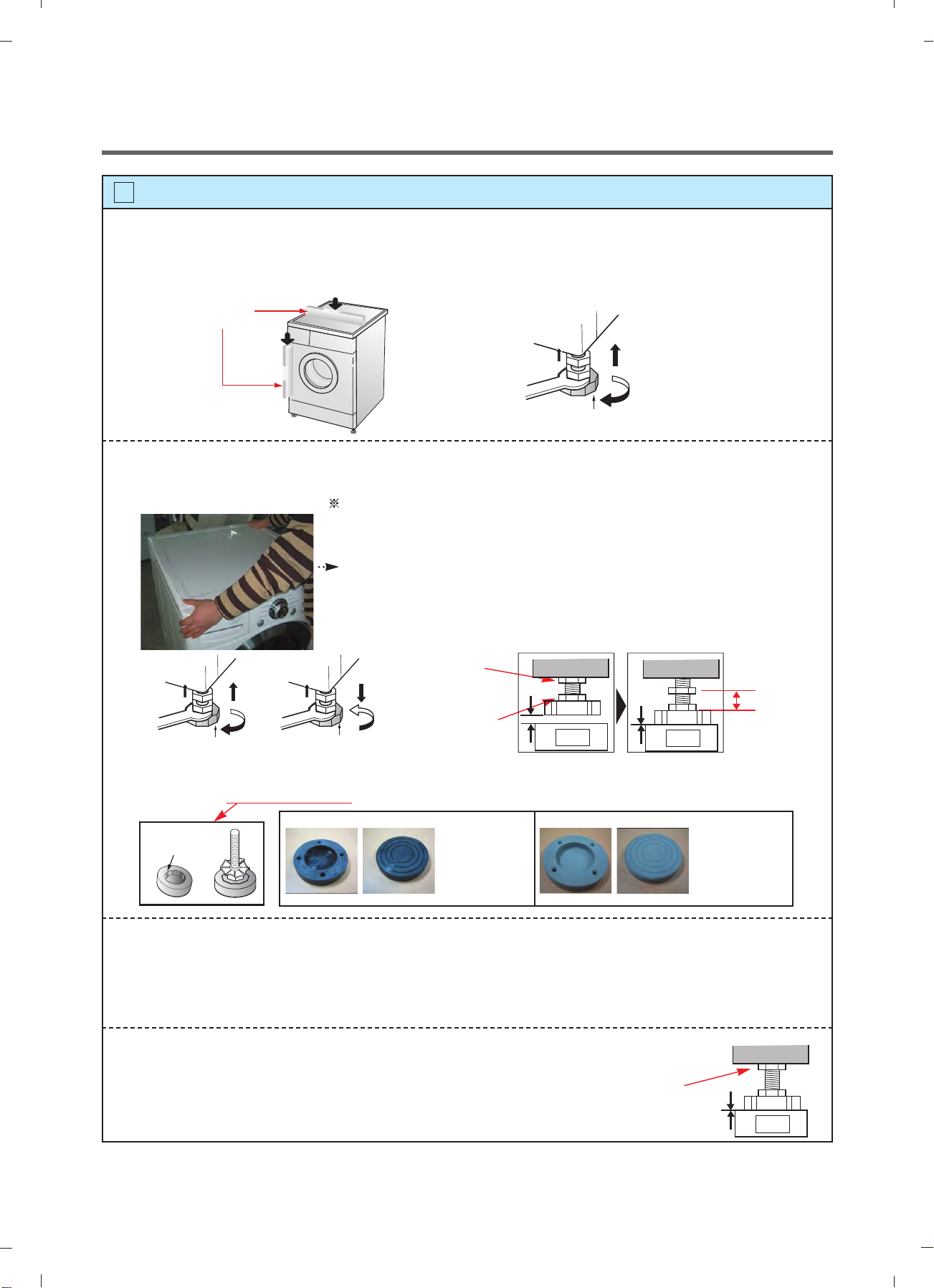
8
Check the horizontality with a level (Gage).
Step 1
If washing machine legs are loose or not Screwed in, then tighten with the spanner wrench.
Using the level, level the washing machine from front to back and side to side.
A level
Higher
Tighten
Adjustable feet
Step 2
Use the spanner wrench to adjust Legs until level and try the Diagonal test.
Diagonal test
How to perform a diagonal test:
Place your right hand on the back, right corner and your left hand on the front,
left corner of the unit, then attempt to rock the unit from corner to corner.
Then, move your right hand to the front, right side and your left hand to the
back, left corner and attempt to rock the unit from corner to corner.
If the unit is level, it will not rock. However, if the unit is not level, it will rock.
If the unit rocks, it will be necessary to adjust the leveling feet of the unit.
Adjust the foot under the hand that is on the front of the machine.
Lock nut
Adjustabl
e bolt
Gap
Floor
No Gap
Floor
Tighten
Higher
Adjustable feet
Lower
Tighten
Adjustable feet
Lower the foot until there is no gap between floor and foot.
And only use adjustment rubber when difference at the leg adjustment is more than 10mm.
Rubber Cup
Rubber Cup
4620ER4002A
(Black)
for Tile floors
4620ER4002B
(Gray)
for Wooden floors
10mm
Step 3
Perform a Rinse and Spin with some clothing in the machine.
To do this, put 2~3kg of clothing in the unit, turn on the unit, Select the Rinse+Spin
and then start. When the unit reaches the spin cycle, watch for vibrations.
If the unit is vibrating, make small adjustments to the leg until they subside. (Repeat step 2)
Step 4
Tighten the lock nut against the base of the machine to lock the position leg.
Tighen the lock nut
11
No Gap
Floor
Page 12
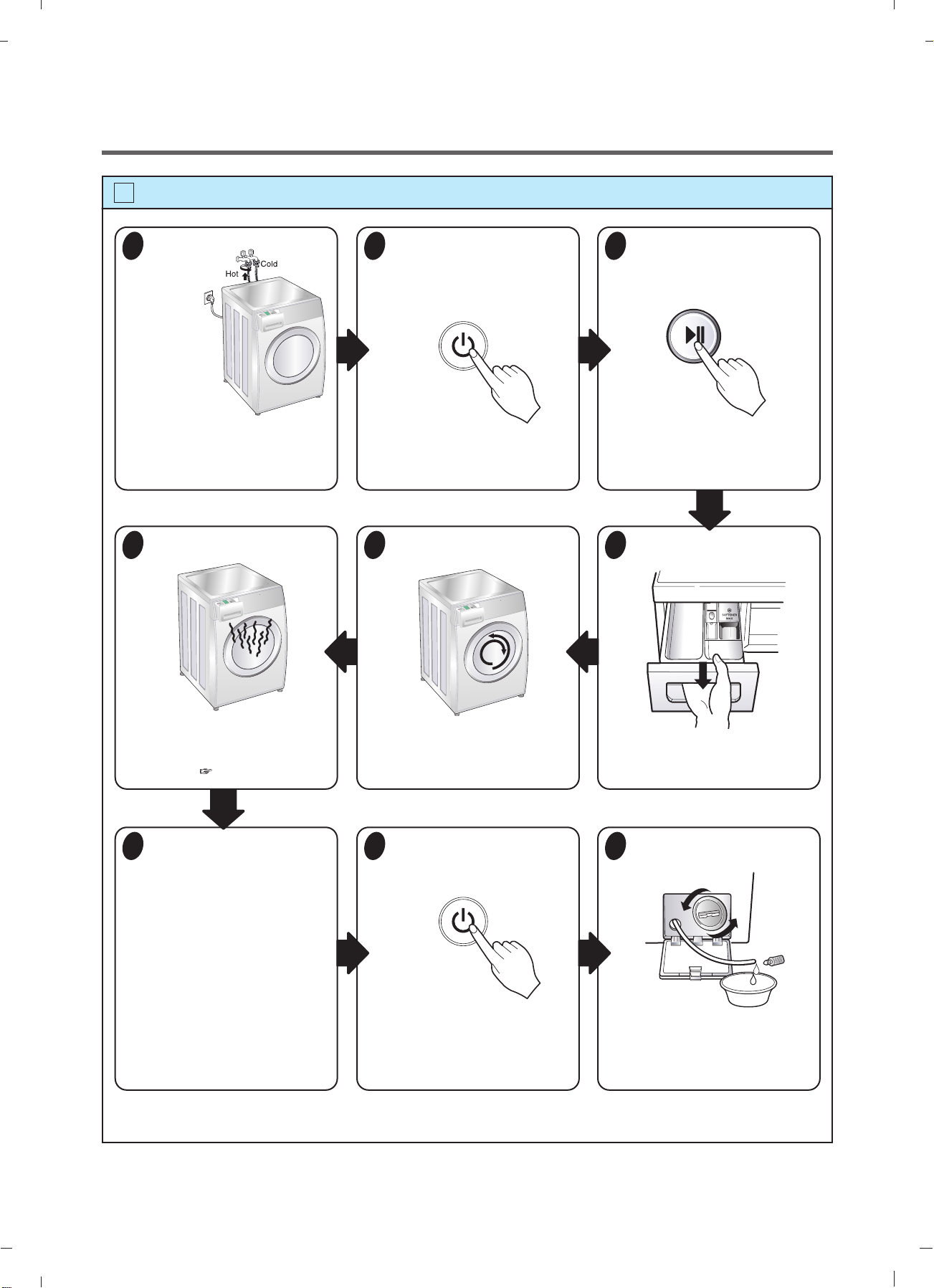
9
Test operation
Preparation
1
for
washing.
· Connect the power plug to the
outlet.
· Connect the inlet hose.
Check the water heating.
6
Press the power button.
2
Check automatic reverse turn.
5
Press the START/PAUSE
3
button.
· In case of Coloreds program.
Check the water supply.
4
· Touch the Temp and Medic
Rinse button simultaneously and
the present temperature will be
displayed.
Check the drain and spin
7
functions.
· Turn power off and then power on.
· Select the spin rpm
· Press the START PAUSE button.
· Check the spin and drain
functions.
Page 20
· Check if the drum rotates
clockwise and counterclockwise.
Turn power off and open
8
the door.
· Turn power off and then power on.
· Listen for a click to determine if the
door is unlocking.
· Check if water is supplied through
the detergent dispenser.
Water removal.
9
· If SVC is needed during check,
remove the remaining water by
pulling out the hose cap.
12
Page 13
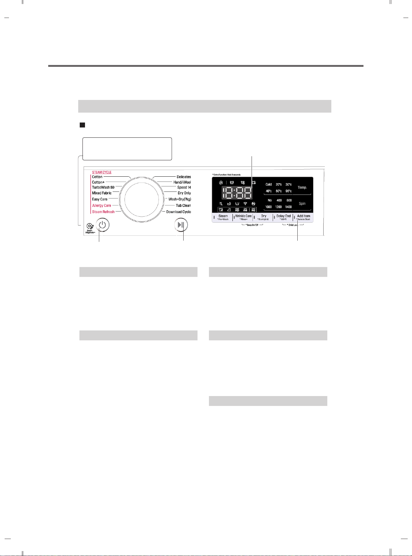
5. OPERATION
How to use washer
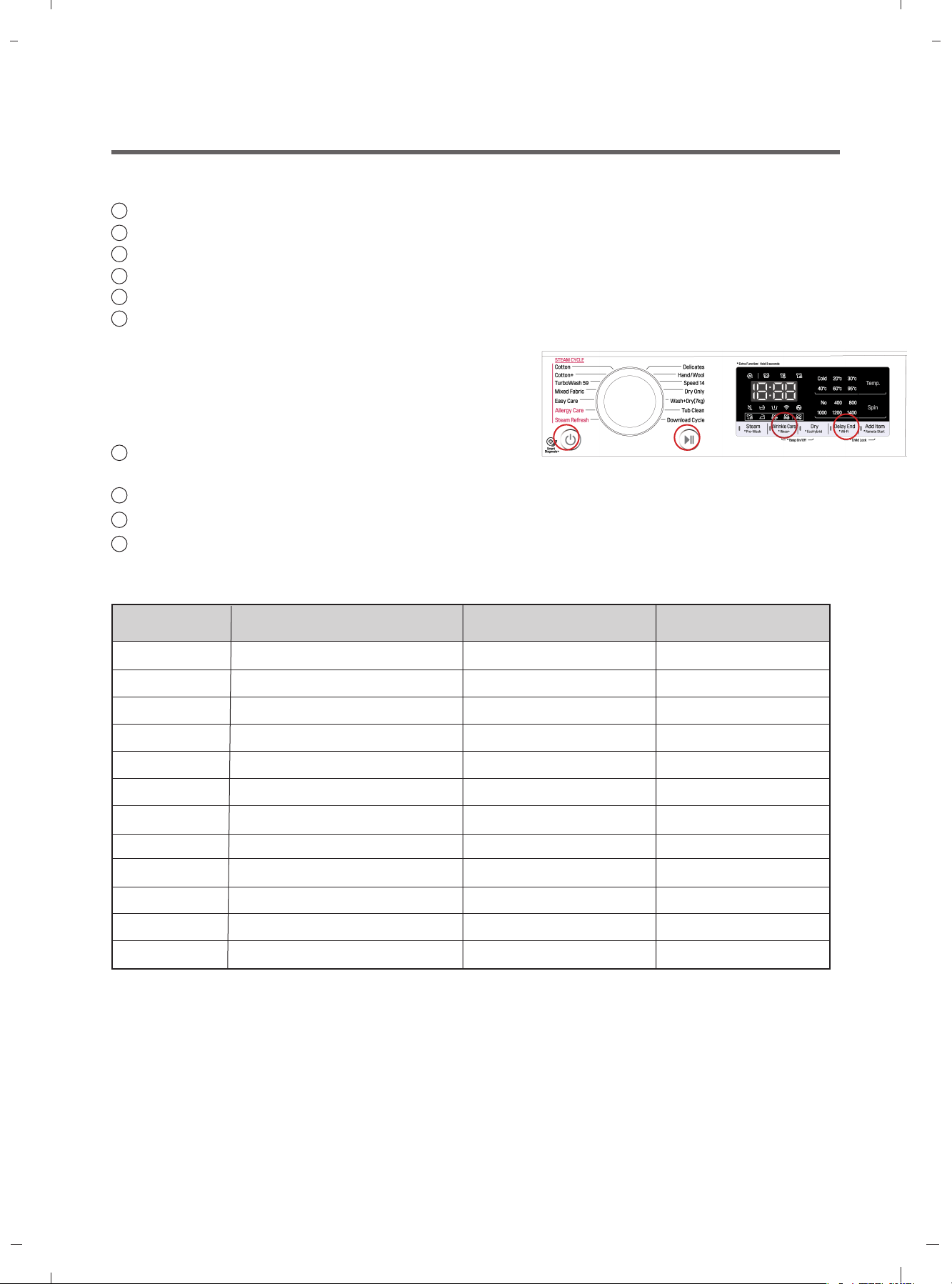
Control panel
SmartDiagnosis™ function is
available only for the products with
a SmartDiagnosis™ mark.
LED display
Power Button
Program dial
Start/Pause
Button
Power
Press the Power button to turn power on
and off.
To cancel the Time Delay function, the
power button should pressed.
Start/Pause
This Start/Pause button is used to start
wash cycle or pause the wash cycle.
If temporary stop of wash cycle is
needed, touch the Start/Pause button.
When in Pause, the power is turned off
automatically after 4 minutes.
Options
Program Dial
Programs are available according to the
laundry type.
Lamp will light up to indicate selected
program.
LED display
The display shows the settings, estimated
time remaining, options, and status
messages for your washer.
The display will remain on through the
cycle.
Options
This allows you to select an additional
cycle and will light when selected.
Use thise buttons to select the desired
cycle options for the selected cycle.
13
Page 14
How to use washer
Options
Steam: This option is featured with the
enhanced washing performance. This
option consumes low energy.
Rinse + ( ) : Add rinse once.
Dealy End :
You can set a time delay so that the washing
machine will start automatically and finish
after a specifed time interval.
NOTE
The delay time is the time to the end of the
programme, not the start. The actual running
time may vary due to water temperature, wash
load and other factors.
To cancel the function, the power button
should be pressed.
Avoid using liquid detergent for this option.
1. Touch the Power button.
2. Select a washing programme.
3. Touch the Time Delay button and set time
required.
4. Touch the Start/Pause button.
14
Page 15
How to use washer
Temp.
By touching the Temp. button the water
temperature can be selected.
- Cold
- 20°C, 30°C, 40°C, 60°C, 95°C
Water temperature can be selected
according to the program.
Spin
yb detceles eb nac level deepS nipS
touching 'Spin' button repeatedly.
ylnO nipS
1. Touch the Power button.
2. Touch the Spin button to select RPM.
3. Touch the Start/Pause.
NOTE
When you select , it will still rotate for a
short time to drain quickly.
Pre Wash
If the laundry is heavily soiled, “Pre Wash”
course is effective.
1. Touch the Power button.
2. Select a cycle.
3. Touch the Pre Wash button.
4. Touch the Start/Pause button.
Wrinkle Care
This washing programme reduces wrinkles by
steaming after spin.
1. Press the Power button.
2. Select a washing programme.
3. Press the Wrinkle Care button for 3 seconds.
4. Press the Start/Pause button.
15
Page 16
How to use washer
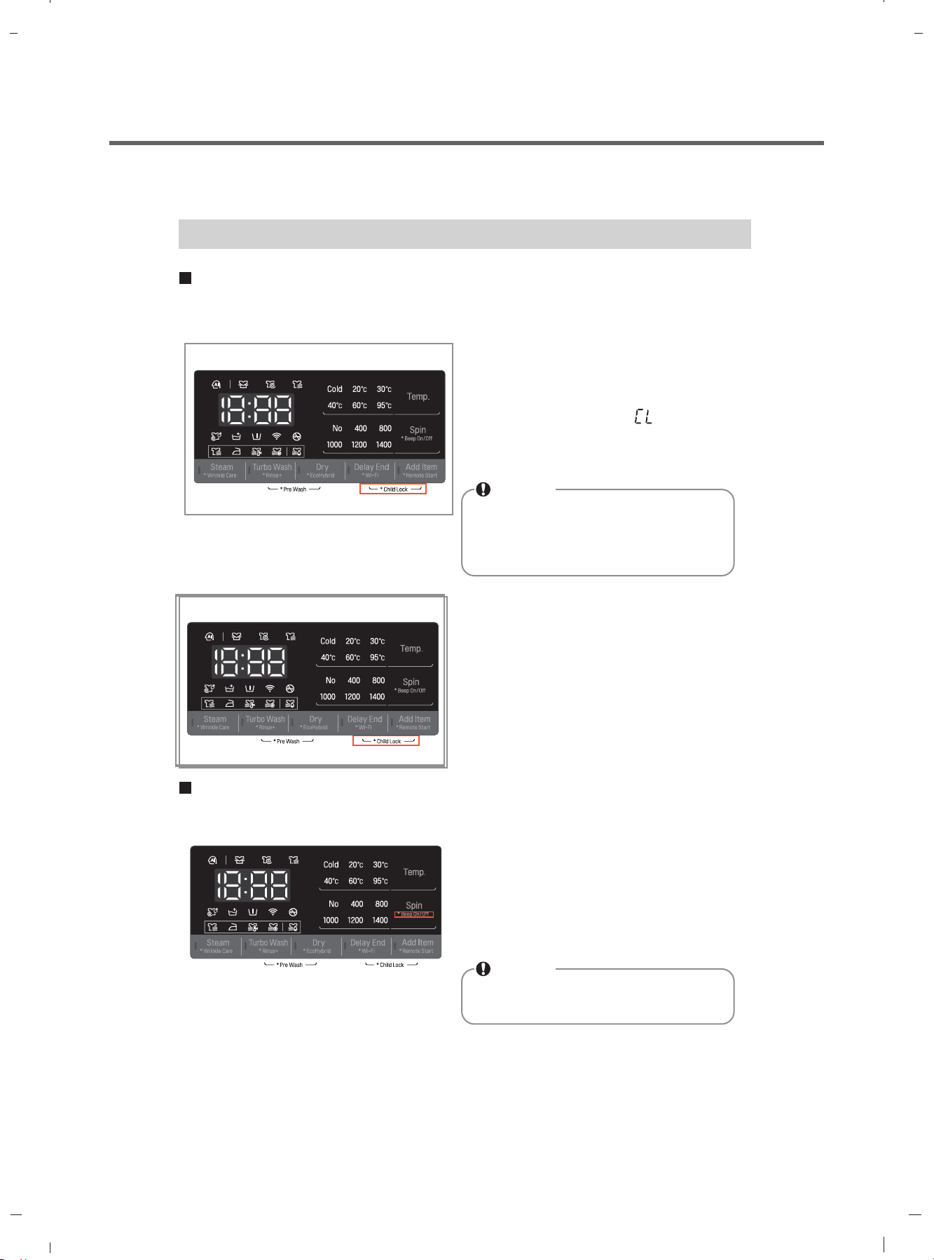
Child Lock
Select this function to lock the buttons on the control assembly to prevent tampering.
"Child Lock" can be set only during the washing cycle.
Locking the control panel
1. Touch and hold the Child Lock button for
3 seconds.
2. A beeper will sound, and ' ' will appear on
the LED display.
When the child lock is set, all buttons are
locked except the Power button.
NOTE
Turning off the power will not reset the
child lock function. You must deactivate
child lock before you can access any
other functions.
Unlocking the control panel
1. Touch and hold the Child Lock button for
3 seconds.
2. A beeper will sound and the remaining time
for the current programme will reappear on
the LED display.
Beep On / Off
The Beep on/off function can be set only during the washing cycle.
1. Touch the Power button.
2. Touch the Start/Pause button.
3.
Touch and hold the Spin button
three seconds to set Beep on/off function.
Once the Beep on/off function is set, the setting
is memorized even after the power is turned off.
NOTE
If you want to turn the Beeper off,
simply repeat this process.
16
Page 17
How to use washer
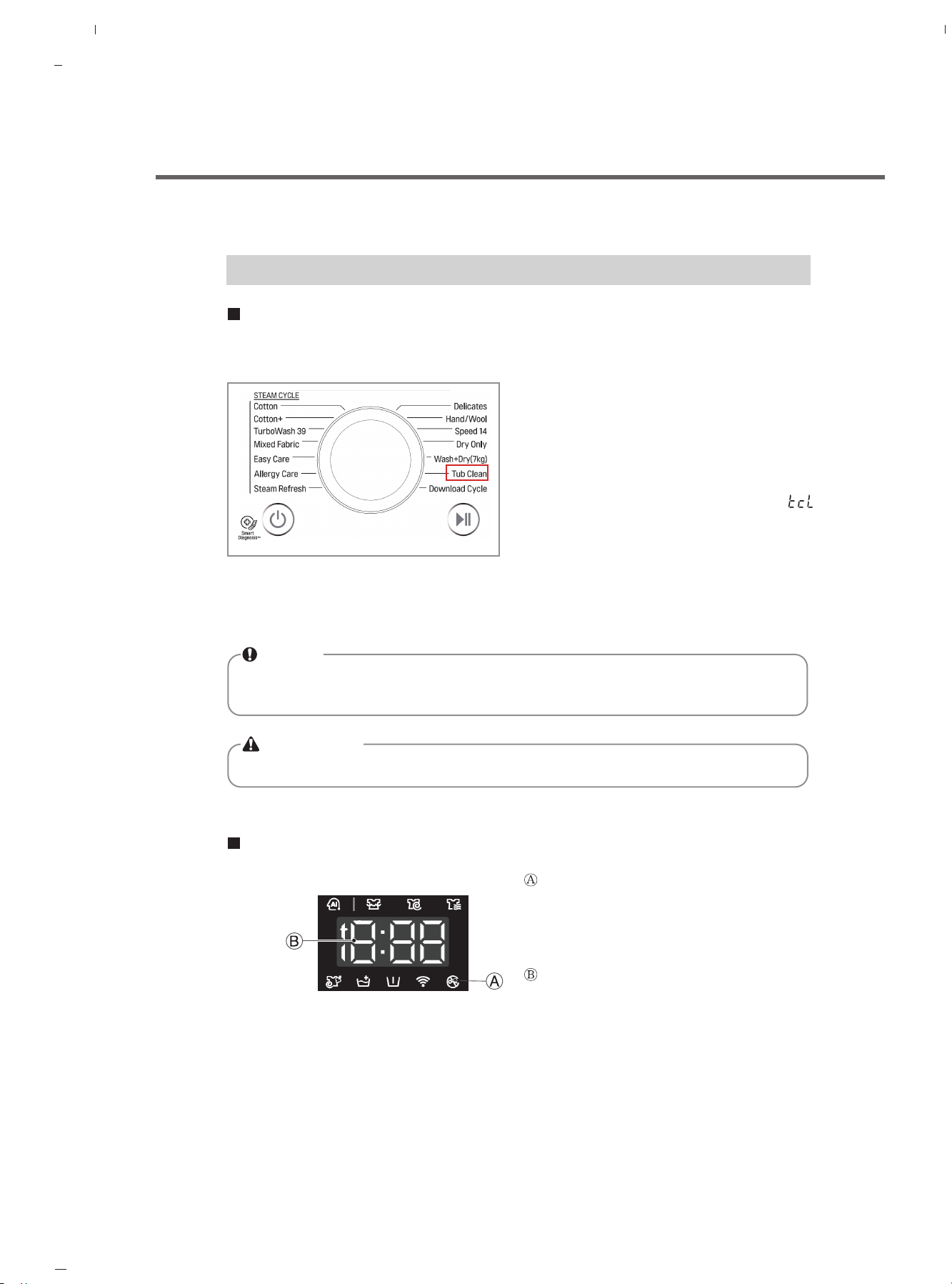
Tub Clean
Tub Clean is a special cycle to clean the inside of the washing machine.
A higher water level is used in this cycle at higher spin speed . Perform this cycle regularly.
1. Remove any clothing or items from the
washer and close the door.
2. Open the dispenser drawer and add Anti
limescale(e.g. Calgon) to the main wash
compartment.
3. Close the dispenser drawer slowly.
Power On and select the Tub
4.
displayed on the display.
5
. Touch the Start/Pause button to start.
6. After the cycle is complete, leave the door
open to allow the washer door opening,
flexible gasket and door glass to dry.
NOTE
Do not add any detergent to the detergent compartments.
Excessive suds may generate and leak from the washer.
Clean .Then will be
CAUTION
If there is a child, be careful not to leave the door open for too long.
Door Lock & Detecting
“Door Lock” - For safety reasons, the
door will lock while machine is in use and the
“Door Lock” icon will light up. You can safely
open the door after the “Door Lock” icon
turns off.
While "Detecting" is shown on the
display the washing machine rotates slowly
and detects how much laundry is loaded in
the drum.
It will take a short time.
17
Page 18
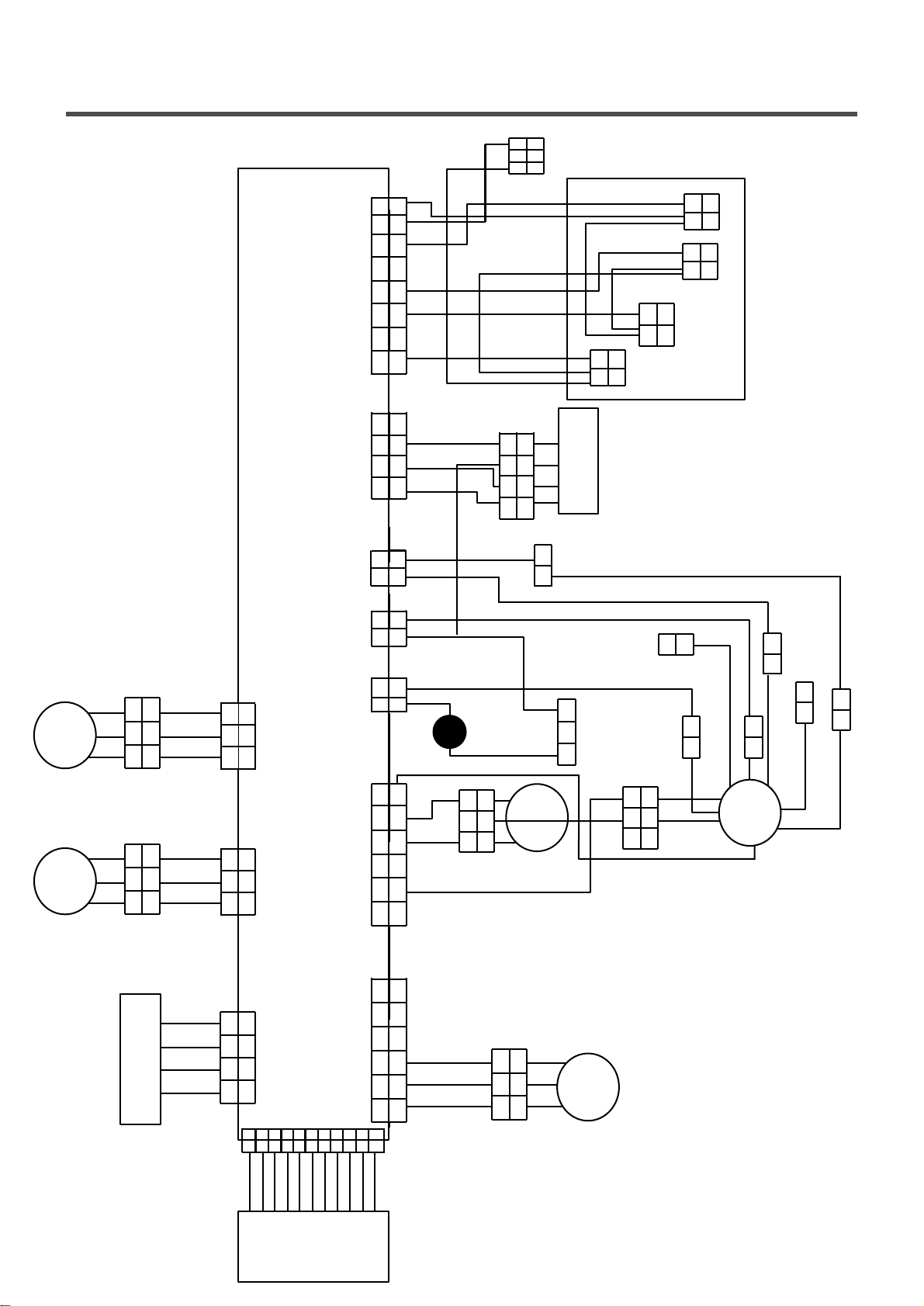
6. WIRING DIAGRAM/PCB LAYOUT
YL
BK
8
8
7
7
YL BK
BL
NA8NA4
PL
WH
123 456
123 456
GY
BKRD
1 2 3
1 2 3
Flow meter
BL
1 2
BK BK
GY
1 2
BL
BK
BK
BK BK
1 2
1 2
Pre
1 2
Filter Clean
WH
BK
1 2
1 2
BK
1 2
Steam
Main
Inlet V/V
1 234
1 234
YL/RD BL BK
GR
NA
1 2
1 2
BK
YL
BK
WH
YL
BK
WH
RD BL YL
YL3
123
123
BL6
Main PCBA
GY3
123
123
YL
BK
123
Fan Motor
Motor
123
BL YL
123
123
RD
RD
1 2
1 2
BR
1 2
1 2
BL YL
OR PL WHLBDR BS
123 456
123 456
BL
1 2 3 4
1 2 3 4
YL/RD
123
OR WH PL
Pressure
123
Door S/W
1 1
1
1
Earth
BLBR
Earth
3 2 1
Noise Filter
WH
Switch
WH SB
YL
1 1
2 312 3
1
1 1
BK
Earth
RD
1 1
RD
1 1
TH
Heater
1 1
NA5
GY6
1 234
Vibration Sensor
1 234
RD BL BK YL
1 101
10 11
CN11
1 2 3
1 2 3456
1 2 3456
YL BK OR
1 2 3 4 5 6 7 8 9
1 2 3 4 5 6 7 8 9
1 2 3
YL BK OR
Drain
Pump
Display PCBA
18
Page 19
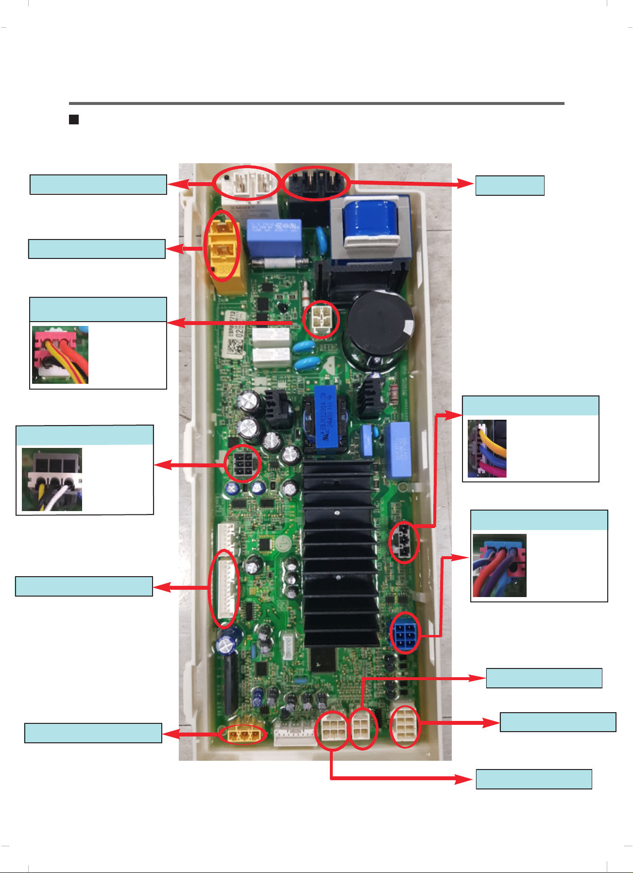
PCB Layout (Main)
Dry Heater
PCB POWER
Door Switch
yellow&red:door switch
black:door switch
orange:door switch
Drain motor
BLDC pump
white:U
black:V
yellow:W
Heater
Moter Stator Control
V-U/U-W
/W-V
→R:8~11Ω
Display
Dry Fan motor
Water sensor
blue&white:thermister
blue:common
violet:pressure switch
orange:pressure switch
Vibration Sensor
DC Valve
Thermistor
19
Page 20
7. TROUBLESHOOTING
7-1. CHECK BEFORE SERVICE
1
Before servicing ask the customer what the trouble is.
2
Check the adjustments. (Power supply :220-240V~, Removal of transit bolts etc..)
Check the troubles referring to the troubleshooting.
3
Decide service steps referring to disassembly instructions.
4
Then, service and repair.
5
After servicing, operate the appliance to see whether it works OK or NOT.
6
7-2. LOAD TEST MODE
1
Turn on, and touch ‘Wrinkle Care’ and ‘Delay End’
at the same time in 1 second.
2
The washer must be empty and the controls must be in the off state.
Press Power with above two buttons pressed and then buzzer will sound.
3
Press the Start/Pause button repeatedly to cycle through the test modes
4
0
1
2
3
4
5
6
7
8
9
10
11
Turns on all light and locks the door.
Tumble clockwise
Low speed spin
High speed spin
Inlet valve for prewash turns on.
Inlet valve for main wash turns on.
Inlet valve for hot water turns on.
Inlet valve for atomizing turn on.
Tumble counterclockwise
Heater turns on for 3 sec.
Drain pump turns on.
Off
Display StatusNumbers Check Point Remark
PGM Version Information
rpm(42~50)
rpm (60)
rpm (130~140)
Water level frequency
Water level frequency
Water level frequency
Water level frequency
rpm
Water temperature
Water level frequency
-
For Hot&Cold Model
20
Page 21
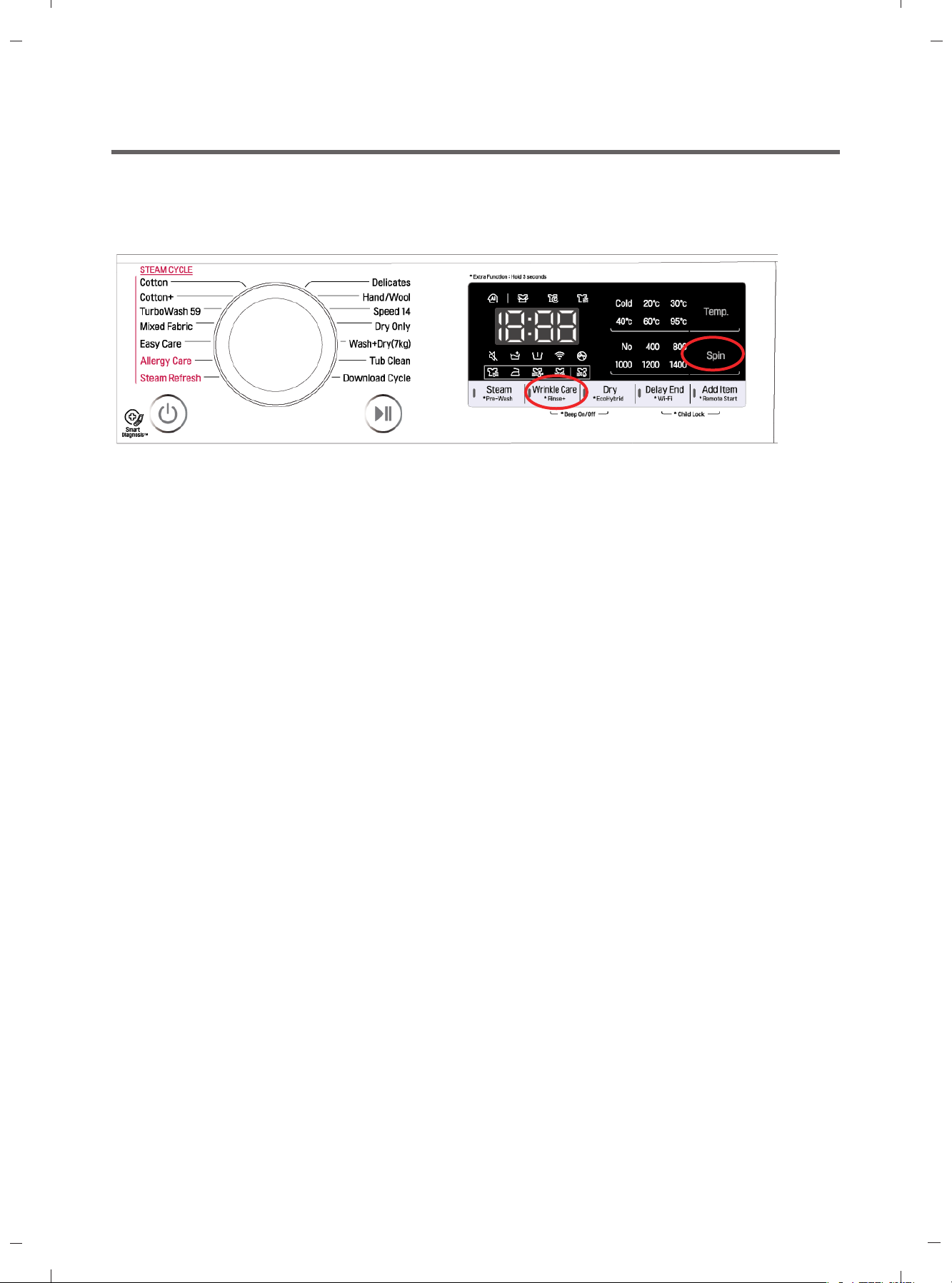
7-3. HOW TO CHECK THE WATER LEVEL FREQUENCY
Touch the Spin
Keeping touch, the digits indicate the water level frequency.
and Wrinkle Care button simultaneously.
21
Page 22

7-4. ERROR DISPLAY
If you press the Start/Pause button in error condition, any error except will disappear and the
machine will change into the pause status.
In case of
error is not resolved within 4 min., the power will turn off automatically and the error only will blink.
But in the case of
, , if the error is not resolved within 20 sec., and in case of all other errors, if the
, the power will not turn off.
ERROR SYMPTOM CAUSE
1
2
3
4
5
6
WATER INLET
ERROR
WATER OUTLET
ERROR
OVERFLOW
ERROR
PRESSURE SENSOR
S/W ERROR
DOOR OPEN
ERROR
UNBALANCE
ERROR
Not reached the water level(248) within 10 minutes
after water supplied or not reached to the preset
water level within 25 minutes.
Not fully drained within 10 minutes.
Water is overflowing (under 21.3kHz).
If " " is displayed, the drain pump operates
to drain the water automatically.
The pressure sensor switch is out of order.
In case of operating the reservation function or the
other function with door opened. Close the door,
then the error display is resolved.
The door switch is out of order.
The appliance is tilted.
Laundry is gatherd to one side.
Page 24
Page 26
Page 28
Page 29
Page 31
Page 25
THERMISTOR(HEATING)
7
ERROR
The THERMISTOR is out of order.
22
Page 33
Page 23

ERROR SYMPTOM CAUSE
8
9
10
11
MOTOR
FROZEN FAILURE
VIBRATION SENSOR
ERROR
LOCKED
ERROR
POWER
FAILURE
The connector in the LEAD WIRE ASSEMBLY is
not connected to the connector of STATOR
ASSEMBLY.
Reconnect or repair the connector.
Page 36
The washer experienced a power failure
Press the start/pause button
Supply warm water into the drum and unfreeze drain
hose and drain pump. Wet a towel in warm and
apply to supply hose.
Malfunction of vibration sensor
12
DRY HEATER
ERROR
• The Dry Heater is out of orde
• The Connector of the Dry Heater is not connecte
properly to the connector in the
Main PWB ASSEMBLY
• The Dry fan motor is out of orde
23
Page 24

7-5. TROUBLESHOOTING WITH ERROR
Symptom Check Point
1.INLET VALVE
ERROR
Steam&Condensate
Pre wash
1.Check Electric Wiring.
2.Check Inlet valve’s Resistance.
3.Check Inlet valve clogged.
4.Voltage of the inlet valve’s connector.
- LQC mode : Valve running with 13.6V ± 10%
- In normal cycle : Valve running with 7V±10%
Need to check 2s later from valve start to running
Filter Cleaan
Main wash
24
Page 25

Water Inlet Error (IE)
[Note] Environmental safety check list
1. No water tap leakage or freeze 4. No entanglement of water supply hose.
2. No water shortage. 5. No water supply hose leakage
3. The inlet filter is not cloggeed.
Is the water tap closed ?
YES
NO
When there is water in the tub,
is the water level frequency
over 26.0khz ?
YES
NO
Is the Connector connected correctly to the
and the Inlet Valve ? is the Harness alright ?
YES
Check the Water tap and open it fully.
Check the Air Chamber and the Tube (clogged)
Check the water level frequency again,
if it is over 26.2KHz, replace the Pressure switch.
Main PCB
NO
Reconnect or repair the Connector .
Or replace the Harness .
Is the resistance of each lnlet valve within 3.5 ~4.5 k ?
1
Pre Valve
1
1
Main Valve
2
2
YES
When the washing machine is started, is the inlet valve
operating?
NO
NO
Replace the Inlet Valve .
Replace the Main PCB .
25
Page 26

Unbalanced Error (UE)
Does the load lean toward one
side, or is the load a few items?
NO
Is the laundry mixed?
NO
YES
YES
The few items of clothing will clump together
and their weight will be in one place on the drum,
throwing the weight off during spin mode.
So add some laundry to overcome UE error.
And rearrange load to allow proper spinning.
Try rearranging the laundry in drum
Or the laundry is separated by size, type, and color.
Separate by size,
type and color
Is the washing machine installed
at an angle?
YES
Adjust the height of washing
machine to be kept horizontally.
( Page 7)
26
Page 27

Water Outlet Error (OE)
Is the drain hose kinked ?
YES
NO
Is the Pump filter clogged ?
YES
NO
Next Page
* How to disassemble and clean pump filter
Open the Cover by coin or
finger(only new model)
Drain water by removing the
hose cap.
Check drain hose for kink and straighten the Hose.
Drain Hose
Check & Clean Pump Filter.
This kind of accumulation on the drain filter not only
prevents proper drainage, but also will promote
bacteria growth and cause odors.
This drain filter should be cleaned once a month.
Disassemble the pump
filter by turning the filter
cap counterclockwise.
Pump Filter
Cover
Filter Cap
Filter clogged by foreign objectsAssemble & close cap
filter CapHose Cap
Clean the filter
27
Page 28

Is the Standpipe Height greater
than1.0 m above the floor?
NO
YES
Observe Standpipe Height requirements
of 1.0m maximum.
- Your washer will not be able to drain out
water adequately, if the standpipe exceeds 1.0 m.
In this case, water may flow back into the washer.
When there is no water in the
pump casing, is the water level
frequencyover 26.0khz ?
YES
Is the Connector connected correctly to
the Main PCB and the Pump Motor ?
Or is the Harness alright ?
YES
Or is the Impeller operating normally?
Binding
NO
NO
Check the Air Chamber and the Tube (clogged).
Check the water level frequency again, if it is over
25.5KHz, replace the If it is clogged, Pressure
switch.
Reconnect or repair the Connector .
Or replace the Harness .
YES
Replace the Pump Motor.
NO
Does the Pump motor start, when the spin mode
starts?
YES
If the drain hose blocked?
28
NO
YES
Replace the Main PCB .
Clean the drain hose.
Page 29

FE (Overflow Error)
Power off for 10sec. Then power on.
Is the water level over reference line and is the water level f requency under 21.3kHz?
* Water level frequency
- Touch and Hold 'Spin' & 'Turbo Wash'
simultaneously.
NO
Is water continuously
coming into the drawer?
YES
Replace the Main PCB.
Replace the Inlet Valve assembly.
NO
YES
Drain out the water and then
check the Air Chamber and the Tube (clogged).
If FE is displayed again,
then replace the Pressure Switch .
If FE is displayed again,
then replace the Main PCB .
29
Page 30

Pressure Sensor S/W Error (PE)
Is the Connector connected correctly to
the Main PCB and the Pressure Switch ?
Is the Harness alright ?
YES
Is the resistance of the Pressure Switch
out of range?
[Pin1 ~ Pin3]
21~23 )
NO
YES
Reconnect or repair the Connector .
Or replace the Harness .
Replace the Pressure Switch .
NO
Is the air chamber and the tube clogged?
NO
Replace the Main PCB .
YES
Check air chamber and remove foreign material.
30
Page 31

Symptom Check Point
1.PRESSURE
SENSORERROR(PE)
1.Check Electric Wiring.
2.Check Pressure sensor’s Resistance.
3.Check Air Chamber and Tubeclogged.
Pressure Sensor
(3)
(2)
(1)
BL6
31
Page 32

Door Open Error (dE2)
Is the door closed?
YES
Is the Door assembly in line with door switch ?
Scratch by Latch Hook
or
Touching
YES
NO
Does the Spring of Latch Hook actuate?
YES
NO
NO
Close the door fully.
Lift up & Close the door.
If the dE is displayed, Replace the Door Bracket.
Replace the Spring
Does the Door Switch operate as follows?
* Door Locking time : 1~8 sec.
1
Check the time between from
input the power to parts
move up, then Door locked.
*
Door Releasing time : 25~100 sec.
Check the time between from off the
power to parts
move down, then Door released.
1
1
Door Switch Error (dE1)
Is the Connector connected correctly to
the Main PCB and the Door Switch?
Is the Harness alright ?
YES
NO
NO
Replace the Door switch.
Reconnect or repair the Connector.
Or replace the Harness.
Is there clicking sound once or twice when the
START/PAUSE button is pressed to start the
cycle? No
Replace the MAIN PWB ASSEMBLY.
32
Page 33

Symptom Check Point
1. DOOR OPEN
ERROR(dE)
1.Check Electric Wiring.
2.Check latch hook sping.(Cracked)
3.Check Door switch’s Resistance.
4.Check Voltage of Door switch’s connector.
(5) (3)
(4) (2)
13.1V
33
Page 34

Thermistor (Heating) Error (tE)
Is the Connector connected correctly to
the Main PCB and the Thermistor and the Heater?
Is the Harness alright ?
Heater for Washing
NO
Is the resistance of the Thermistor out of range 44 ~
53 K at 25°C? (Page 17)
NO
YES
YES
Reconnect or repair the Connector .
Or replace the Harness .
Replace the Thermistor .
Is the resistance of the Heater out of range 24.5 ~
28.5 (for Washing) ? (Page 19)
NO
Replace the Main PCB .
[Note] Thermistor Spec
S
P
E
C
Temp
30 °C
40 °C
60 °C
70 °C
95 °C
105 °C
Resistance (k )
MIN
36.35 39.45 42.72
24.20 26.05 27.97
11.43 12.12 12.82
8.088 8.514 8.940
3.544 3.791 4.045
2.617 2.816 3.023
STD MAX
YES
Replace the Heater.
34
Page 35

Symptom Check Point
1.HEA TING ERROR(tE) 1.Check Electric Wiring.
2.Check Heater’s Resistance.
3.Check Thermistor’s Resistance.
4.Water Leaked into the Thermistor’s Connector.
Wash Heater
Heater
Wash Heater
(1) ~ (2)
Main
PWB
BK 3
YL 3
th
WH
BK
Resistance
[ ]
~
th
12 ~ 18
35
Page 36

Wash Thermistor
WH6
Thermistor
Wash
Thermistor
(1) ~ (2)
Main
PWB
NA3 4
NA3 5
th
~
th
Resistance
[k ]
39.5 86(30)
26.1 104(40)
12.1 140(60)
8.5 158(70)
3.8 203(95)
2.8 221(105)
Remarks
(℃)
℉
36
Page 37

Motor Locked Error (LE)
[Pre Check]
Gentle wash cycles, such as Perm Press, Delicates, Hand Wash, and Wool/Silk should only be used for smaller loads.
Because these cycles are more gentle in tumbling and spinning, putting too much in the drum can register an issue
with the motor. Remove items, reset unit and test with a Rinse/Spin cycle.
Press the Power button & Start / Pause button.
Does the Drum stop when the start/pause button is pr essed to start the cycle ?
Or Sometimes does the Drum rotateweakly (under 15rpm)?
YES
Is the Connector connected correctly to
the Main PCB and the Motor?
Is the Harness alright ?
YES
Disassemble the Rotor .
Is the Magnet of rotor cracked or broken?
NO
Is the resistance the same
betweenStator points?
V~U / U~W / W~V : 8~11
V U W
Magnet
V U W
NO
YES
NO
Reconnect or repair the Connector .
Or replace the Harness .
Replace the Rotor .
Replace the Stator.
Replace the Main PCB .
YES
37
Page 38

Symptom Check Point
1. NO POWER 1.Check Electric Wiring.
2.Check the Customer’s outlet.
3.Check Noise Filter.
4.Check LED on in Main PWB
Noi se Fi lter
(3)
Noise Filter
WH1
(1)
(3)
(1)
Resistance
[Ω]
(2)
(1)
(3)
(3)
(1)
RD1
WH1 (1) ~ RD1 (3) 0
WH1 (3) ~ RD1 (1) 0
38
Page 39

8.TROUBLESHOOTING WITHOUT ERROR CODES
PF (Power Failure or no power)
Is the Power Plug connected
firmly to the power outlet?
And is the supply voltage
220~240V AC?
YES
Is Multi-plug socket used ?
NO
Is the Connector connected correctly to
the Main PCB and the Noise Filter ?
Is the Harness alright ?
NO
YES
NO
Reconnect Power Plug firmly.
Check the fuse or
reset the circuit breaker.
Don’t use Multi-plug socket.
Use Single Plug socket for
washing machine.
Reconnect or repair the Connector .
Or replace the Harness .
Noise Filter PCB
YES
Is Red LED ON while power supplied ?
YES
Is the connectors connected
Correctly to the Display
PCB?
Main PCB
NO
YES
Check and replace Main PCB .
Check connectors otherwise.
Replace Display PCB .
39
Page 40

Vibration & Noise During Spin
Have all the Transit Bolts been removed?
Washer
Packing Support
NO
Remove the Transit Bolts
YES
Refer to INSTALLATION . (Page 7)
40
Page 41

Detergent & Softener does not flow in
Is water supplied?
YES
YES
Is detergent & softener put in
the correct compartment of the drawer?
Main Wash
(Powder)
Pre Wash
(Powder)
YES
Only
softener
NO
NO
Reference (Amount of Detergent & Softener)
Detergent
Refer to [Water Inlet Error (IE) ]
(page 23)
Put it in the Correct Position .
Softener
Is the Detergent caked or hardened ?
YES
Clean the drawer and dispenser.
NO!!
OK!!
Check point
41
Page 42

Water Leak
1. Water Leak from Dispenser
Is the Dispenser Tray Damaged or warped?
NO
Is detergent & softener put in
the correct compartment of the drawer?
Only
softener
YES
NO
Reference (Amount of Detergent & Softener)
Replace the Dispenser Tray .
Put it in the Correct Position .
Main Wash
(Powder)
YES
Is the Detergent caked or hardened ?
YES
Clean the drawer and dispenser.
Pre Wash
(Powder)
Detergent
Softener
NO!!
OK!!
Check point
42
Page 43

2. Water Leak from Dispenser
Are the gasket (seal)
and door cleaned regularly?
YES
Is the door or gasket damaged?
3. Unknown – Water on Floor
Are the inlet hoses loose or cracked/split?
Check!!
NO
YES
YES
Clean the periphery of Gasket and Door regularly.
Replace the damaged parts.
Replace the Inlet Hoses .
NO
Is the washer horizontal ?
YES
Are the drain filter and manual
drain hose open?
NO
NO
Adjust the height of washing machine to be kept
horizontally. (Page 7)
Turn the filter cap clockwise to close.
43
Page 44

Application Installation
Using the Wi-Fi Function
Search for the LG Smart ThinQ application
from the Google Play Store on a smart phone.
Follow instructions to download and install the
application.
Product Registration
Run the LG Smart ThinQ application on a
1
smart phone.
Create an account and sign in.
2
Select Register.
3
Select Front Load Washer.
4
Follow the instruction on the smart phone.
5
Communicate with the appliance from a smart
phone using the convenient smart features.
Using the Application
Select the appliance in the application.
1
Select the menu on the upper right side to
2
access settings and features.
Washer Cycle
Set or download any perferred cycle and operate
by remote control.
Tub Clean Coach
Check the appropriate Tub Clean period by
washing frequency.
NOTE
• To verify the Wi-Fi connection, check the Wi-Fi
icon(
• LG Smart
network connection problems or any faults,
malfunctions, or errors caused by network
connection.
•
The machine supports 2.4 GHz Wi-Fi networks
only
If the appliance is having trouble connecting
•
to the Wi-Fi network, it may be too far from
the router.Purchase a Wi-Fi repeater (range
extender) to improve the Wi-Fi signal strength.
•
The Wi-Fi connection may not connect or may
be interrupted because of the home network
environment.
•
The network connection may not work properly
depending on the internet service provide
•
The surrounding wireless environment can
make the wireless network service run slowly
The application is subject to change for
•
appliance improvement purposes without
notice to users.
) on the control panel is lit.
ThinQ is not responsible for any
.
r.
.
Energy Monitoring
Check the energy consupmtion of the recently
used cycles and monthly average.
Smart Diagnosis
This function provides useful information for
diagnosing and solving issues with the appliance
based on the pattern of use.
Settings
Various functions are available.
Push Alert
Turn on the Push Alerts to receive appliance
triggered even if the LG Smart ThinQ application
is off.
44
Page 45

Open Source Software Notice
Information
To obtain the source code under GPL, LGPL,
MPL, and other open source licenses, that is
contained in this product, please visit http://
opensource.lge.com.
In addition to the source code, all referred
license terms, warranty disclaimers and
copyright notices are available for download.
LG Electronics will also provide open source
code to you on CD-ROM for a charge covering
the cost of performing such distribution (such as
the cost of media, shipping, and handling) upon
email request to opensource@lge.com. This
offer is valid for three (3) years from the date on
which you purchased the product.
Declaration of Conformity
Hereby, LG Electronics European Shared
Service Center B.V., declares that this Washing
machine is compliant with the essential
requirements and other relevant provisions of
Directive 1999/5/EC. The complete Declaration
of Conformity may be requested through the
following postal address:
LG Electronics European Shared Service Center
B.V.
Krijgsman 1
1186 DM Amstelveen
The Netherlands
or can be requested at our dedicated DoC
website: http://www.lg.com/global/support/cedoc/
cedoc#
This device is a 2.4 GHz wideband transmission
system, intended for use in all EU member
states and EFTA countries.
For consideration of the user, this device should
be installed and operated with a minimum
distance of 20 cm between the device and the
body.
Wireless LAN Module
Model LCW-004
Frequency
Range
Output Power
(Max.)
45
IEEE 802.11 b : 17.82 dBm
IEEE 802.11 g : 17.72 dBm
IEEE 802.11 n : 16.61 dBm
2412~2472 MHz
Page 46

Using the Smart Diagnosis™
Function
Smart Diagnosis™ Through the
Customer Information Centre
Should you experience any problems with the
appliance, it has the capability of transmitting
data to a smart phone using the LG Smart ThinQ
application or via the phone to the LG Customer
Information Centre.
Smart Diagnosis™ can not be activated unless
the appliance is turned on by pressing the
Power button. If the appliance is unable to turn
on, then troubleshooting must be done without
using Smart Diagnosis™.
Smart Diagnosis™ Using a Smart
Phone
Open the LG Smart ThinQ application on the
1
smart phone.
Select the appliance and then the menu on
2
upper right side.
Select the Smart Diagnosis, then press
3
Start Smart Diagnosis button.
NOTE
• If the diagnosis fails several times, use the
following instructions.
Press the Power button to turn on the
1
washing machine. Do not press any other
buttons or turn the programme knob.
When instructed to do so by the call center,
2
place the mouthpiece of your phone close to
the Power button.
Max.
10 mm
Press and hold the Temp. button for 3
3
seconds, while holding the phone mouthpiece
to the icon or Power button.
Keep the phone in place until the tone
4
data transfer is displayed.
• For best results, do not move the phone
while the tones are being transmitted.
• If the call centre agent is not able to get an
accurate recording of the data, you may be
asked to try again.
Select the Try Again or Audible Diagnosis.
4
Follow the instructions on the smart phone.
5
Keep the phone in place until the tone
6
on the phone.
Once the countdown is over and the tones
5
have stopped, resume your conversation with
the call centre agent, who will then be able to
assist you using the information transmitted
for analysis.
NOTE
• The Smart Diagnosis™ function depends on
the local call quality.
• The communication performance will improve
and you can receive better service if you use
the home phone.
• If the Smart Diagnosis™ data transfer is poor
due to poor call quality, you may not receive
the best Smart Diagnosis™ service.
46
Page 47

WARNING
• Unplug the washing machine before cleaning
to avoid the risk of electric shock. Failure to
follow this warning may result in serious injury,
• Never use harsh chemicals, abrasive cleaners,
or solvents to clean the washing machine.
Cleaning Your Washing
Machine
Care After Wash
•
the inside of the door seal to remove any
moisture.
• Leave the door open to dry the drum interior.
• Wipe the body of the washing machine with a
dry cloth to remove any moisture.
Cleaning the Interior
• Use a towel or soft cloth to wipe around the
washing machine door opening and door glass.
• Always remove items from the washing
machine as soon as the cycle is complete.
Leaving damp items in the washing machine
can cause wrinkling, colour transfer, and odour.
• Run the Tub Clean programme once a month
(or more often if needed) to remove detergent
buildup and other residue
Cleaning the Water Inlet Filter
• Turn off the supply taps to the machine if the
washing machine is to be left for any length of
drain (gully) in the immediate vicinity.
•
icon will be displayed on the control panel
when water is not entering the detergent
drawer.
• If water is very hard or contains traces of lime
Cleaning the Exterior
Proper care of your washing machine can
extend its life.
Door:
• Wash with a damp cloth on the outside and
inside and then dry with a soft cloth.
Exterior:
• Immediately wipe off any spills.
• Wipe with a damp cloth.
• Do not press the surface or the display with
sharp objects.
clogged. It is therefore a good idea to clean it
occasionally.
Turn off the water tap and unscrew the water
1
supply hose.
2
47
Page 48

9. Par t i nspect i on
48
Page 49

49
Page 50

50
Page 51

51
Page 52

I
I
I
I
I
I
I
I
II II I
II II I
I I
II
I
I
I
I
I
52
Page 53

10. DISASSEMBLY INSTRUCTIONS
Remove the power cord from the outlet before disassembling or repairing the unit.
CONTROL PANEL ASSEMBLY
Screws
1
Unfasten the screws from the parts displayed
in the fig.
2
Disassemble the top plate assembly by sliding
it back and then lifting it up.
3
Pull the drawer panel assembly out.
4
Unfasten the screws from the parts displayed
in the fig.
5
Unfasten the screws from the parts displayed
in the fig.
6
Disconnect the wiring connectors between the
multi harness and the control panel assembly.
Disassemble the control panel assembly.
7
8
Disassemble the display PCB assembly from
the control panel assembly by unfastening the
screws.
*When re-assemble should fasten by screw
(4EA)
9
53
10
Disconnect the wiring connector between the
Display PCB assembly and the NFC
PCB assembly.
Page 54

PWB ASSEMBLY(MAIN)
1
Unscrew four screws.
2
Disassembly back cover assembly.
3
Unscrew the screw.
4
Pull the PWB assembly in direction of red
arrow.
DISPENSER ASSEMBLY
5
Disassembly PWB like the picture.
1
The plate assembly(Top) are disassembled.
2
Pull the drawer to arrow direction.
3
Two screws are unscrewed.
4
Clamp
5
Cutting cable ties and the ventillation hose
are disassembly on the dispenser
54
Page 55

INLET VALVE
1
Disconnect the wiring connector.
2
Remove the valve by two screws of the valve
holder.
When reconnecting the connector
1
VALVE (
Main Wash)
White/Black
DOOR
VALVE
VALVE (
VALVE
Rating : 12V
Resistant : 3.5~4.5 k
1
Open the door completely.
2
Remove the three screws from the hinge.
When removing the Door Assembly, it is
necessary to hold the Bracket that is inner of
the Cabinet Cover.
Removing method of remained water
2
(Steam)
Pre Wash)
3
4
(Filter Clean)
Purple/Black
Gray/Black
Blue/Black
Pull it out from hose.
First, prepare a bucket to put in the remained
water.
CAP(REMAING HOSE)
55
Page 56

CABINET COVER
1
The plate assembly(Top) is disassembled.
2
Pull out the drawer and unscrew 2 screws.
3
Lift the side the Control Panel Assembly and
pull it out
1
Two screws are unscrewed.
2
Push the hook( , ) below.
3
Unscrew the screws from the lower cover .
2
Disassembly cap cover and pump case.
3
Unscrew the screw from the CABINET COVER.
Remove gasket clamp and release gasket from
④
cabinet cover.
2
1
retfa LORTNOC ,YLBMESSA LENAP tuo hsuP
56
Page 57

4
Lift and separate the cabinet cover.
1
2
SWITCH ASSY, DOOR LOCK
NOTE :
When assembling the CABINET
COVER, connect the Door S/W connector.
1
Two screws are unscrewed and disassembly
cabinet cover.
2
The Door Lock S/W is disconnected form the
wiring connector and the strap.
57
Just check cut-off.
Check the operating time.
1
* Door Locking time : 1~8 sec.
Check the time between from
input the power to parts
move up, then Door locked.
*
Door Releasing time : 25~100 sec.
Check the time between from off
the power to parts
move down, then Door released.
1
1
Page 58

ROTOR ASSEMBLY, STATOR ASSEMBLY, FRICTION DAMPER
1
Remove the back cover.
2
After loosening the bolt, Rotor, pull out the
rotor.
1
Remove the 6 bolts from the stator.
2
Disconnect the 2 connectors.
Motor Stator
V ~ U (8~11 )
U ~ W (8~11 )
W ~ V (8~11 )
1
Remove the hinges (Damper) at the Tub.
2
The Hinge(Damper) at the base is pulled off by
pressing on the snaps at the sharp end.
3
The hinge at the base is pulled off.
(In directions of the arrow)
U V W
58
Page 59

Bellows
Pump
Hose
PUMP
1
Disassembly Top Plate, Control Panel,
Drawer Panel Assembly, Cabinet Cover
Assembly, Lower Cover Assembly
4
Remove pump outlet hose.
5
Remove tub pump bellows.
6
Remove cap(Remaining Hose).
7
Disconnect the wiring.
8
Three screws are unscrewed from the cabinet.
Remaining
Hose
HEATER
9
Remove the pump to arrow direction.
Rating : 26V
Resistant : 3.46~3.98
1
Loosen the nut.
2
Remove washing heater by pulling out.
< Heater for Washing>
Rating : 230V 2000W
Resistant : 24.5~28.5
CAUTION
When assembling the washing heater, insert
the heater to heater clip on the bottom of tub
and check the position of wire color.
59
Page 60

WHEN FOREIGN OBJECT STUCK BETWEEN DRUM AND TUB
1
Remove washing heater.
2
Remove the foreign object(wire,coin,etc) by
inserting long bar in the hole.
60
Page 61

How to disassemble Vibration sensor (Only for Vivace 550 model)
1
Open the top plate by removing 2ea screws.r.
2
Cut cable ties from tub cover.
3
Remove the vibration sensor housing from the Harness
4
Remove the vibration sensor from tub cover.
61
Page 62

How to disassemble Pressure sensor(for Vivace 460, 550 model)
1
Open the top plate by removing 2ea screws.r.
2
Remove the EPDM hose and connector from the pressure sensor.
3
Turn the pressure sensor 90 degrees counterclockwise. And remove it
※If there is no separate hole, the hook shape of pressure sensor
should be broken and separated.(Replace with new one)
※When assembling, the embossed shape of the hook
should be aligned in the circular hole.(For horizontal fixing)
62
Page 63

EXPLODE VIEW AND PART LIST
THE PART LIST OF CABINET ASSEMBLY
A154
A134
A103
A102
A104
A106
A150
A133
A440
A130
A151
A141
F120
A140
A152
A310
A110
A101
A100
A430
A410
A200
A135
A303
A276
A220
A485
A201
COLD (BLUE)
A450
Page 64

THE EXPLODED VIEW OF CONTROL ANEL &
DISPENSER ASSEMBLY
F300
F310
F225
F433
F462
F321
F160
F432
F430
F220
F441
F110
F210
Page 65

THE EXPLODED VIEW OF
F140
K411
K410
K655
DRUM & TUB ASSEMBLY
K350 K360 K143
K123
K122K121
K125
K320
K140
K510
K444
K141
K110
K111
K130
K150
K115
K320
K105
K410
K135
K610
K611
K349
K344
K340
K131
F468
K151
F461
K520 K540
F467
K530
K571
K570
K550
K572
Page 66

11-4. THE EXPLODED VIEW OF DRYER
M100
M110
M120
65
Page 67

59
P/No.: MFL69882928
 Loading...