

Page 1

0
Service Manual
(F1)
LG Electronics
Page 2

1
Ch 1. Service information
Ch 2. Locations
Ch 3. System information
· Specification
· System Block Diagram
· Fn key combinations
· Status indicators
· BIOS Flash
· BIOS Setup
Ch 4. Symptom-to-part index
· Power system checkout
· Numeric error codes
· Error messages
· LCD-related symptoms
· Indeterminate problems
Ch 5. Removing and replacing a part (FRU)
Ch 6. Part list
· Part list
· Exploded view
Contents
Page 3
2
Chapter 1. Service information
1-1. Important service information
Strategy for replacing parts (FRU-Field Replaceable Units)
Before replacing parts
Make sure that latest BIOS and drivers are installed before replacing any parts (FRUs) listed in this
Caution
The BIOS configuration on the computer you are servicing may have been customized.
Running Automatic Configuration my alter the settings. Note the current configuration settings;
then, when service has been completed, verify that those settings remain in effect.
Strategy for replacing a hard-disk drive
You have to get a User’s approval before formatting or replacing a hard-disk drive. You must let the User
know that the us er is responsible for the loss data
Caution
The drive startup sequence in the computer you are servicing may have been changed. Be
extremely careful during write operations such as copying, saving, or formatting. If you select an
incorrect drive, data or programs can be overwritten.
Use the following strategy to prevent unnecessary expense for replacing and servicing parts
1. If you are instructed to replacing a part but the replacement does not correct the problem, reinstall the
original part before you continue.
2. Some computers have both a processor board and system board. If you are instructed to replace either
the processor board or the system board, and replacing one of them does not correct the problem,
reinstall that board, and then replace the other one.
3. If an adapter or device consists of more than one part, any of the parts (FRUs) may be the cause of the
error. Before replacing the adapter or device, remove the parts (FRUs), one by one, to see if the
symptoms change. Replace only the part that changed the symptoms.
Ch1. Service information
Page 4
3
1-2. Safety notices
Warning
Before the computer is powered-on after part (FRU) replacement, make sure all screws, springs,
and other small parts are in place and are not left loose inside the computer. Verify this by
shaking the computer and listening for rattling sounds. Metallic parts or metal flakes can cause
electrical shorts.
Warning
some standby batteries contain a small amount of nickel and cadmium. Do not disassemble
a standby battery, recharge it, throw it into fire or water, or short-circuit it. Dispose of the battery
as required by local ordinances or regulations. Use only the battery in the appropriate parts
listing. Use of an incorrect battery can result in ignition or explosion of the battery
Warning
The battery pack contains small amounts of nickel. Do not disassemble it, throw it into fire or
water, or short-circuit it. Dispose of the battery pack as required by local ordinances or
regulations. Use only the battery in the appropriate parts listing when replacing the battery pack.
Use of an incorrect battery can result in ignition or explosion of the battery.
Warning
If the LCD breaks and the fluid from inside the LCD gets into your eyes or on your hands,
immediately was the affected areas with water for at least 15 minutes. Seek medical care if any
symptoms from the fluid are present after washing.
Warning
To avoid shock, do not remove the plastic cover that protects the lower part of the inverter card.
Warning
Though the main batteries have low voltage, a shorted or grounded battery can produce enough
current to burn personnel or combustible materials.
Warning
Before removing any part (FRU), turn off the computer, unplug all power cords from electrical
outlets, remove the battery pack, and then disconnect any interconnecting cables.
Ch1. Service information
Page 5
4
1-3. Safety information
General safety
Follow these rules to ensure general safety
· Observe good housekeeping in the area of the machines during and after maintenance.
· When lifting any heavy object
1. Ensure you can stand safely without slipping.
2. Distribute the weight of the object equally between your feet.
3. Use a slow lifting force. Never move suddenly or twist when you attempt to lift.
4. Lift by standing or by pushing up with your leg muscles
(This action removes the strain from the muscles in your back.)
· Do not attempt to lift any object weights more then 16kg(35lb) or object that you think are too heavy for you.
· Do not perform any action that causes hazards to the customer, or that makes the equipment unsafe.
· Before you start the machine, ensure that other service representatives and the customer’s personnel are
not in a hazardous position.
· Place removed covers and other parts in a safe place, away from all personnel, while you are servicing the
machine.
· Keep your tool box away from walk areas so that other people will not trip over it.
· Do not wear loose clothing that can be trapped in the moving parts of a machine. Make sure that your
sleeves are fastened or rolled up above your elbows. If your hair is long, fasten it.
· Insert the ends of your necktie or scarf inside clothing or fasten it with a nonconductive clip, approximately
8 centimeters(3 inches) from the end.
· Do not wear jewelry, chains, metal-frame eyeglasses, or metal fasteners for you clothing.
· Wear safety glasses when you are hammering, drilling, soldering, cutting wire, attaching springs, using
solvents, or working in any other conditions that might be hazardous to your eyes.
· After service, reinstall all safety shields, guards, labels, and ground wires. Replace any safety device that
is worn or defective.
· Reinstall all covers correctly before returning the machine to the cust omer.
Caution
Metal objects are good electrical conductors.
Ch1. Service information
Page 6
5
Electrical safety
Observe the following rules when working on electrical equipment.
Important
Use only approved tools and test equipment. Some hand tools have handles covered with a soft
material that does not insulate you when working with live electrical currents.
Many customers have, near their equipment, rubber floor mats that contain small conductive
fibers to decrease electrostatic discharges. Do not use this type of mat to protect yourself from
electrical shock.
· Find the room emergency power-off switch, disconnecting switch, or electrical outlet. If an electrical outlet.
If an electrical accident occurs, you can then operate the switch or unplug the power cord quickly.
· Do not work alone under hazardous conditions or near equipment that has hazardous voltages.
· Disconnect all power before
1. Performing a mechanical inspection
2. Working near power supplies
3. Removing or installing main units
· Before you start to work on the machine, unplug the power cord. If you cannot unplug it, ask the customer
to power-off the wall box that supplies power to the machine and to lock the wall box in the off position.
· If you need to work on a machine that has exposed electrical circuits, observe the following precautions :
Ensure that another person, familiar with the power-off controls, is near you.
Caution
Another person must be there to switch off the power, if necessary.
· Use only one hand when working with powered-on electrical equipment. Keep the other hand in your
pocket or behind your back
Caution
An electrical shock can occur only when there is a complete circuit. By observing the above rule,
you may prevent a current from through your body.
· When using testers, set the controls correctly and use the approved probe leads and accessories for that
tester
Ch1. Service information
Page 7

6
· Stand on suitable rubber mats (obtained locally, if necessary) to insulate you from grounds such as metal
floor strips and machine frames.
· Observe the special safety precautions when you work with very high voltages. These instructions are in
the safety sections of maintenance information. Use extreme care when measuring high voltages.
· Regularly inspect and maintain your electrical hand tools for safe operational condition.
· Do not use worn or broken tools and testers.
· Never assume that power has been disconnected from a circuit. First check that it has been powered off.
· Always look carefully for possible hazards in your work area. Examples of these hazards are moist floors,
non-grounded power extension cables, power surges, and missing safety grounds.
· Do not touch live electrical circuits with the reflective surface of a plastic dental mirror. The surface is
conductive such touching can cause personal injury and machine damage.
· Do not service the following parts with the power on when they are removed from their normal operating
places in a machine.
1. Power supply units
2. Pumps
3. Blowers and fans
4. Motorgenerators
and similar units. (This practice ensure correct grounding of the units.)
· If an electrical accident occurs
1. Use caution ; do not become a victim of yourself.
2. Switch off power.
3. Send another person to get medical aid.
Ch1. Service information
Page 8

7
Safety inspection guide
The purpose of this inspection guide is to assist you in identifying potentially unsafe conditions.
As each machine was designed and built, required safety items were installed to protect users and service
personnel from injury. This guide addresses only those items. You should use good judgment to identify
potential safety hazards due to attachment of non-LG features or options not covered by this inspection
guide.
If any unsafe conditions are present, you must determine how serious the apparent hazard could be and
whether you can continue without first correcting the problem.
· Consider these conditions and the safety hazards they present
1. Electrical hazards, especially primary power (primary voltage on the frame can cause serious or fatal
electrical shock)
2. Mechanical hazards, such as loose or missing hardware
Refer to the following checklist and begin the checks with the power off, and the power cord disconnected.
· Checklist
1. Check exterior covers for damage (loose, broken, or sharp edges)
2. Power off the computer. Disconnect the power cord.
3. Check the power cord for :
a. A third-wire ground connector in good condition. Use a meter to measure third-wire ground continuity
for 0.1 or less between the external ground pin and frame ground.
b. The power cord should be the type specified in the parts list.
c. Insulation must not be frayed or worn.
4. Remove the cover.
5. Check for any obvious non-LG alterations. Use good judgment as to the safety of any non-LG
alterations.
6. Check inside the unit for any obvious unsafe conditions, such as metal filings, contamination, water or
other liquids, or signs of fire or smoke damage.
7. Check for worn, frayed, or pinched cables.
8. Check that the power-supply cover fasteners (screw or rivets) have not been removed or tampered with.
Ch1. Service information
Page 9

8
Handling devices that ar e sensi tive to electrostatic discharge
Any computer part containing transistors or integrated circuits (ICs) should be considered sensitive to
electrostatic discharge (ESD). ESD damage can occur when there is a difference in charge between
objects. Protect against ESD damage by equalizing the charge so that the machine, the part, the work mat,
and the person handling the part are all at the same charge.
Note
Use product-specific ESD procedures when they exceed the requirements noted here.
Make sure that the ESD protective devices you use have been certified (ISO9000) as fully effective.
· When handling ESD-sensitive parts :
1. Keep the parts in protective packages until they are inserted into the product.
2. Wear a grounded wrist strap against your skin to eliminate static on your body.
3. Prevent the part from touching your clothing. Most clothing retains a charge even when you are wearing
a wrist strap.
4. Use the black side of a grounded work mat to provide a static-free work surface. The mat is especially
useful when handling ESD-sensitive devices.
5. Select a grounding system, such as those listed below, to provide protection that meets the specific
service requirement.
Note
The use of a grounding system is desirable but not required to protect against ESD damage.
a. Attach the ESD ground clip too any frame ground, ground braid, or green-wire ground.
b. Use an ESD ground or reference point when working on a double-insulated or battery-operated
system. You can use coax or connector-outside shells on these systems.
c. Use the round ground-prong of the AC plug on AC-operated computers.
Ch1. Service information
Grounding requirements
Electrical grounding of the computers is required for operator safety and correct system function.
Proper grounding of the electrical outlet can be verified by a certified electrician.
Page 10

9
When a CD-ROM drive, DVD drive or the other laser product is installed, note the following :
Caution
Use of controls or adjustments or performance of procedures other than those specified here in
might result in hazardous radiation exposure.
1-4. Laser compliance statement
Opening the CD-ROM drive, DVD-ROM drive or the other optical storage device could result in exposure
to hazardous laser radiation.
There are no serviceable parts inside those drives. Do not open
Danger
Emits visible and invisible laser radiation when open. Do not stare into the beam , do not view
directly with optical instruments, and avoid direct exposure to the bean.
1-5. Backup (Standby) RTC battery safety information
When replacing or disposing of the backup (standby) RTC battery, note the following :
Ch1. Service information
Page 11

10
1-6. Read this first
Before you go to the checkout guide, be sure to read this section.
Important Notes
· Only trained personnel certified by LG should service the computer.
· Read the entire FRU removal and replacement page before replacing any FRU.
· Use new nylon-coated screws when you replace FRUs.
· Be extremely careful during such write operations as copying, saving, formatting.
Drives in the computer that you are servicing sequence might have been altered. If you selected an
incorrect drive, data or programs might be overwritten.
· Replace FRUs only for the correct mode.
· When you replace a FRU, make sure the model of the machine and the FRU part number are correct by
referring to the FRU parts list.
· A FRU should not be replaced because of a single, irreproducible failure. Single failures can occur for a
variety of reasons that have nothing to do with a hard ware defect, such as cosmic radiation,
electrostatic discharge, or software errors.
· Consider replacing a FRU only when a problem recurs. If you suspect that a FRU is defective, clear the
error log and run the test again. If the error does not recur, do not replace the FRU.
· Be careful not to replace a non-defective FRU.
What to do first
You must fill out the record form first.
During the warranty period, the customer may be responsible for repair costs if the computer damage was
caused by misuse, accident, modification, unsuitable physical or operating environment, or improper
maintenance by the customer. The following list provides some common items that are not covered under
warranty and some symptoms that might indicate that the system was subjected to stress beyond normal
use. Before checking problems with computer, determine whether the damage is covered under the
warranty by referring to the following :
Ch1. Service information
Page 12

11
The followings are not covered under warranty :
· CD panel cracked from the application of excessive force or from being dropped
· Scratched (cosmetic) parts
· Distortion, deformation, or discoloration of the cosmetic parts
· Cracked or broken plastic parts, broken latches, broken pins, or broken connectors caused by excessive
force
· Damage caused by liquid spilled into system
· Damage caused by improper insertion of a PC Card or the installation of an incompatible card
· Damage caused foreign material in the diskette drive
· Diskette drive damage caused by pressure on the diskette drive cover or by the insertion of a diskette
with multiple labels
· Damaged or bent diskette eject button
· Fusses blown by attachment of a non-supported device
· Forgotten computer password (making the computer unusable)
· Sticky keys caused by spilling a liquid onto the keyboard
The following symptoms might indicate damage caused by non-warranted activities :
· Missing parts might be a symptom of unauthorized service or modification.
· If the spindle of a hard-disk drive becomes noisy, it may have been subjected to excessive force, or
dropped.
Ch1. Service information
Page 13
12
Chapter 2. Locations
Ch2. Locations
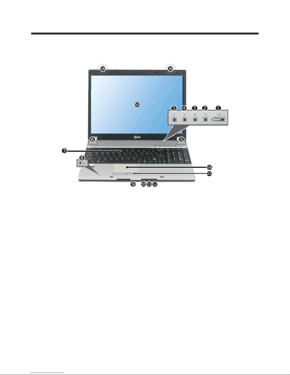
Front view
1. Power button
2. MS Outlook button
3. Internet Explorer button
4. Search button
5. Wireless LAN ON/OFF button
6. Built-in Speakers
7. Keyboard
8. Built-in microphone
9. 4-in-1 (SD/MMC/Memory Stick/Memory Stick Pro) Card Slot
10. Line-in port
11. Microphone port
12. Headset, S/PDIF port
13. Touchpad button
14. Touchpad
15. LCD
16. Wireless LAN Antennas Wireless LAN is optional.
Page 14
13
Ch2. Locations
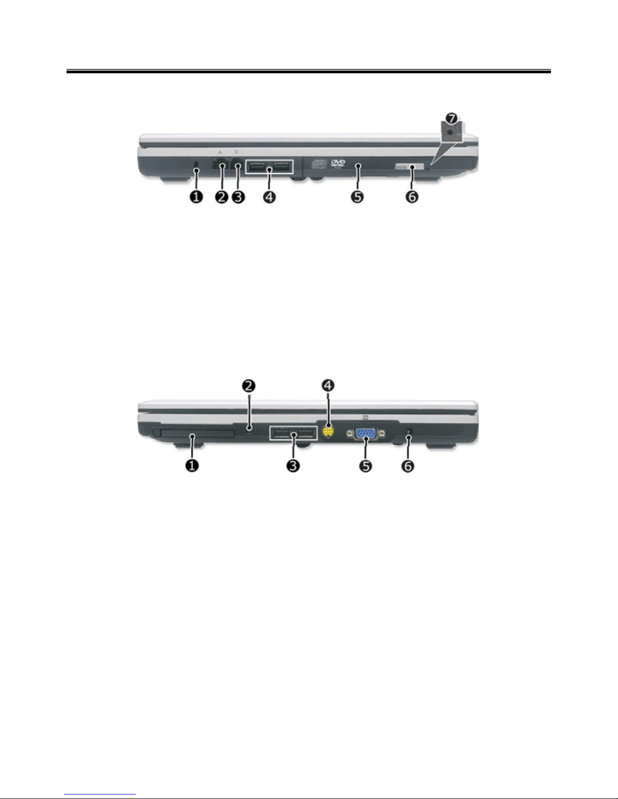
Left view
Right view
1. Security Key Hole (Kensington Lock Hole)
2. LAN Port
3. Modem ports
4. USB Port
5. Optical Disk Drive
6. Open Disk Tray button
7. Emergency Ejector
1. PCMCIA card slot
2. IEEE 1394 Port
3. USB Port
4. S-Video port
A 7-pin slot compatible with 4-pin S-Video cables.
5. VGA Port
6. Power Port
Page 15

14
①
Ch2. Locations
Rear view
1. Fan
2. Security Key Hole (Kensington Lock Hole)
Page 16

15
Specification
Chapter 3. System information
Ch3. System information
Processors
Intel Core Solo/Duo/Core Duo 2/ Celeron-m Processor (L2 Cache Size: 1MB /2MB/4MB, FSB:
533MHz/667MHz)
The user must not replace or expand the CPU capacity arbitrarily. The CPU capacity differs depends on model type.
Main Memory
Maximum Size: Each slot is 1024MB and can be expanded to 2048MB.
SO DIMM Type for Memory Expansion: DDR2 SDRAM SO-DIMM (256MB, 512MB, 1024MB)
BIOS ROM
ROM: 4Mbit
Secondary Storage
2.5" Hard Disk Drive (SATA)
The hard disk capacity and the type depend on the notebook PC model.
Supports 4-in-1 ( SD / MMC / Memory Stick / Memory Stick Pro) Card
Optical Disk Drive
The specifications may differ by model type.
LCD
15.4" : WXGA(Resolution 1280 x 800) TFT Color LCD
Authentication for Anticopy Technology
U.S Patent Nos.4,631,603;4,577,216;4,819,908;4,907,093;5,315,448;and 6,516,132. Patent number of
Macrovision.
This product includes the technologies that are possessed by Macrovision and corresponding companies and
protected by the US Patent Law and other related laws. Use of all technologies subject to the copyrights must be
approved by Macrovision in advance. Otherwise, the technologies may only be used for internal display. Do not
disassemble or remodel the product.
External I/O Interface
External VGA Monitor Port: 1
Microphone Input Port (Mic in): 1
Headset/Optical Output Port (S/PDIF): 1
Line-in Port: 1
External Battery Port: 1
USB 2.0 Ports: 4
4-in-1 (SD/MMC/Memory Stick/Memory Stick Pro) Card Slot: 1
RJ 11 (LAN) Port: 1
RJ 45 (LAN) Port: 1
Page 17

16
Ch3. System information
Video
Intel 945GM Integrated Graphic Controller 64M/128M/256 with DVMT
Specifications may differ by model type.
DVMT - Dynamic Video Memory Technology
Sound
Realtek High Definition Audio Codec (ALC883)
Built-in Stereo Speakers
MODEM
Qcom/Actiontec, MD560LMI-2
RJ 11 Jack
LAN
Realtek RTL8111B 10/100/1000 Ethernet Controller
RJ 45 Jack
Weight
Full Installation: 2.7kg
Battery: About 320g
Weight descriptions may differ by model type.
Page 18
17
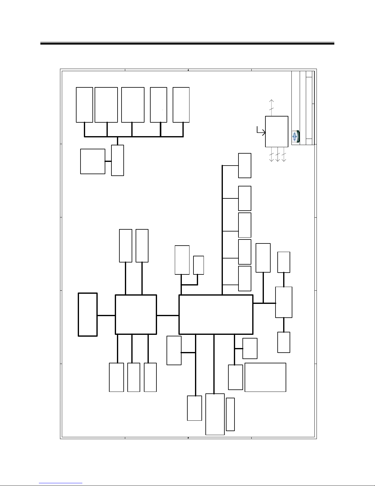
■System Block Diagram
Ch3. System information
5
5
4
4
3
3
2
2
1
1
D D
C C
B B
A A
M S 1034 VER:0C
NORTH
BRIDGE
BRIDGE
SOUTH
INTEL
Yonah 478
DDR-SO D IMM0
KBC
ENE 3910
533/667M HZ
HOST
DMI
Interface
945G M
PCI BUS
ICH7-M
INTEL
Dual Channel DDRII
400/533/667 MHZ
DDR-SO D IMM1
Dual Channel DDRII
400/533/667 MHZ
1466
652
1x Lane PCI-EXPR ESS
LPC BUS
LPC DUBUG
Page 3,4,5
Page 6,7,8,9,10
Page 12
Page 13
Page
17,18,19,20,21
Page 31
Page 31
CRT
LVD S
LVD S
VGA
Page 16
Page 16
TV_O U T
TV_DAC
Page 14
MINI CARD
Page 27
PCIE-LA N
Page 26
USB1.1/2.0
USB 0,1,2,3
Page 22
Connectors
Page 28
USB 4
Bluetooth
Page 27
Mini_P C IE
USB 5
PATA
DVD/CDRO M
Page 23
Page 23
HDD
O Z711M P
Page 24,25
1394 & 3 IN 1 CARD
Azalia
Internal SPK
MIC
LINE IN
Earphone
SPDIF Out
Internal MIC
Page 30 B IOS
Page 31Page 31
TP & KB
ISA
Page 34
SYS PO W ER
Page 35
Page 36
M A X 1999
O Z813
+1_8V S U N
SC 486
IS L6262
+3V +5V
CPU PO W ER
SMDDR_VTERM
CHARGER
Page 38
Page 35
VTT(1.05V )
DC JACK&Selector
+1_5V R U N
Page 37
R TL8111B
Page 28
MDC
A L C 882D
Page 29
33M H Z PCI
100M H Z PCIE
133/166M HZ HO ST
Page 15
CLK GEN
ICS 954310
14M H Z SB
14M H Z CRYSTAL
Cam era
USB 7
Page 22
SD/MMC/MS
M A X 1772
FING ERPRINT
USB 6
Page 28
MS-1034
0.A
BLOCK DIAGRAM
Custom
144Friday, February 17, 2006
Title
Size D ocum ent Number Rev
Date: Sheet of
MICRO-STAR INT'L CO .,LTD .
Page 19

18
Fn key combinations
The following table shows the fun ction of ea ch com bin atio n of Fn with a function key.
Function of Fn keys has nothing to do with Operating System.
Ch3. System information
EndFn + PgDn
HomeFn + PgUp
Changes the status to System standby.Fn + F12
MUTE On/OffFn + F9
Increases the speaker volume. The volume can be adjusted within a 25 grade range.Fn + F8
Decreases the speaker volume. The volume can be adjusted within a 25 grade range.Fn + F7
Increases the LCD brightness. The brightness can be adjusted within a nine-grade range.Fn + F5
Decreases the LCD brightness. The brightness can be adjusted within a nine-grade
range.
Fn + F4
Switches between Touchpad Disable and
Touchpad-Enable. (The initialization takes 1 ~ 2 seconds. It is recommended that you
use it after initialization.)
Fn + F3
Switches the monitors. If you have an external monitor connected, press Fn + F2 keys to
rotate the display mode in order between Default LCD Only, External Only, and Both
Default LCD and External.
Fn + F2
Page 20

19
Status indicators
Ch3. System information
The system status indicators sho w t he st at u s of the com p ut er
1. System On/Off/Standby lamp
- System on standby mode: Blue (Blinking)
- System ON: Off
2. Hard Disk Drive Lamp
- The lamp is turned on when the HDD is running.
Do not turn off the power forcibly while the hard disk drive lamp is on. Otherwise, the data may get impaired.
3. Battery status lamp: The lamp is turned on when the battery is charged.
- While the battery is being charged: Blue
- Charged more than 90%: Green (Blinking)
- Discharged: Off
- AC adapter connected, battery fully charged or removed: Off
- Charged less than 10%: Red
- In faulty state: Red (Blinking)
4. Num Lock lamp
- Num Lock lamp is turned on when you press Num Lock key, indicating the embedded numeric keys are
available. Num Lock lamp is turned off when you press Num Lock key again, indicating the numeric
keypad is not available.
5. Caps Lock lamp
Caps Lock lamp is on when the it is active. When this lamp is on, you can type uppercase letters without
holding Shift key.
6. Scroll Lock lamp
Scroll Lock lamp is on when the it is active.
7. Wireless LAN lamp
- Wireless LAN ON: Off
- Wireless LAN OFF: On
Page 21

20
BIOS Flash
You can update BIOS using a floppy disk drive.
Because this system is not equipped with any floppy disk drive, you have to use an external USB drive for
a BIOS update. In order to boot up with an USB drive, please set Removable Device as the first boot up
drive in the boot menu of BIOS setup.
· How to update flash ROM in DOS
1. Create ‘boot up’ flash update diskette.
2. Copy a ROM image file (*.wph) into the root of the flash update diskette.
3. Copy phlash16.exe to the flash update diskette.
4. Insert the diskette into the FDD of your computer.
5. Boot your computer with the diskette, and type ‘phlash16*.wph /mode=n’.
6. Cold boot and follow the instruction displayed on the screen.
· Flash options /mode=n
0 – Default mode. Keep the current DMI information and update BIOS image only.
1 – Update DMI information only.
If new DMI information is not specified, the current DMI information is left unchanged.
2 – Update BIOS and DMI information.
If new DMI information is not specified, the current DMI information is left unchanged.
3 – Update BIOS and DMI information.
DMI information is updated to the DMI string and options specified in the new BIOS image.
Note
DMI is Desktop Management Interface
Ch3. System information
Page 22
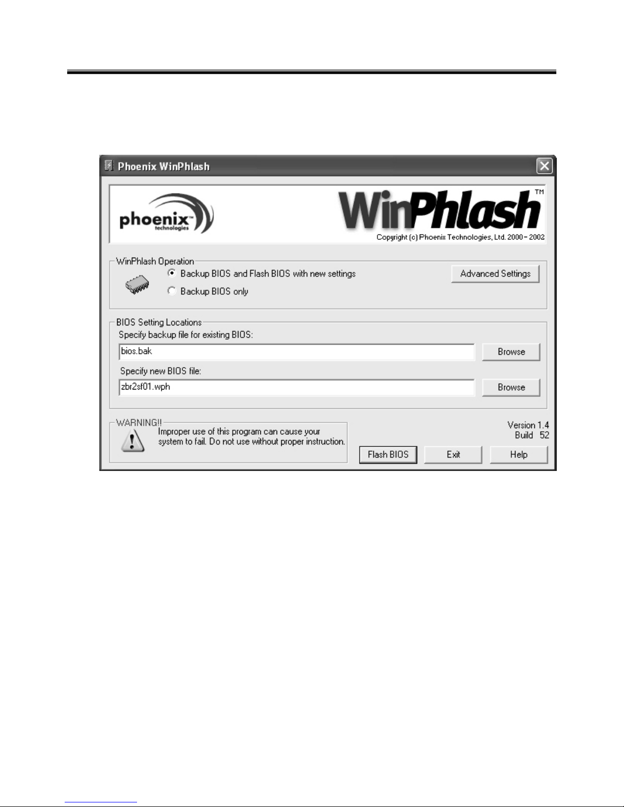
21
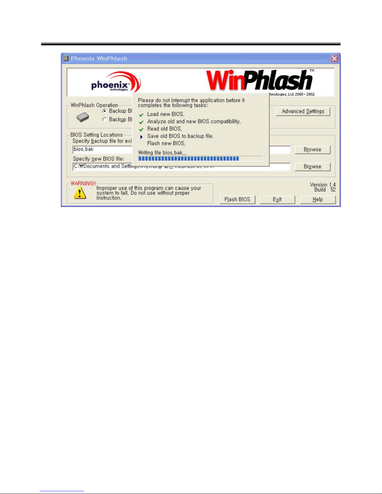
1. Quit all running programs.
2. Start WINPHLASH.EXE.
3. Select the procedure you want :
a. Backup BIOS and Flash BIOS with new settings
b. Backup BIOS Only
4. Specify the locations for backup and new BIOS files in BIOS Setting Locations.
a. Enter the name of the backup file for existing BIOS or click Browse to locate the file.
b. Enter the name of the new BIOS file or click Browse to locate the file.
5. Click Advanced Settings button to access the advanced settings
6. Click Flash BIOS button to start flash BIOS.
7. Wait for the operation to complete. WinPhlash may take one or two minutes to complete flash BIOS
operation.
How to update flash ROM in Windows
Ch3. System information
Page 23
22
8. After the completion, ‘System BIOS was successfully updated’ appears on the screen, then the
computer restarts.
9. After the restart, make sure the system BIOS is updated.
10. If your computer does not restart automatically, turn off your computer and then turn it back on by
pressing power button.
Ch3. System information
Page 24
23
Ch3. System information
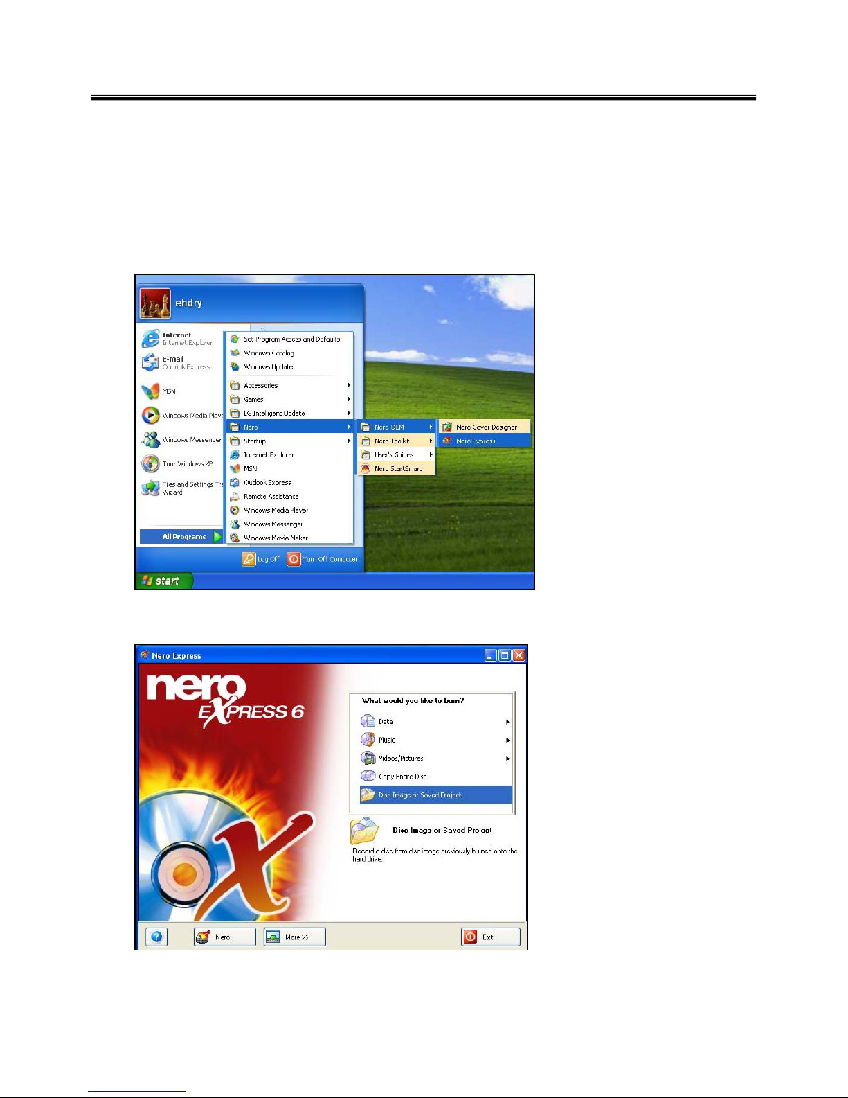
BIOS Release Process and Making Bootable CD
1. LGE(Korea) will send BIOS Image (*.iso) to each Service Centers when we have a new revision.
(Please refer to the BIOS Table (Document No. SBE-HA-01) for latest BIOS)
2. Service center will make Bootable Image CD with Image file(*.iso) as below
a. Insert empty disc to CD-RW Drive and start Nero Burning ROM.
b. Select Disc Image or Saved Project.
Page 25
24
Ch3. System information
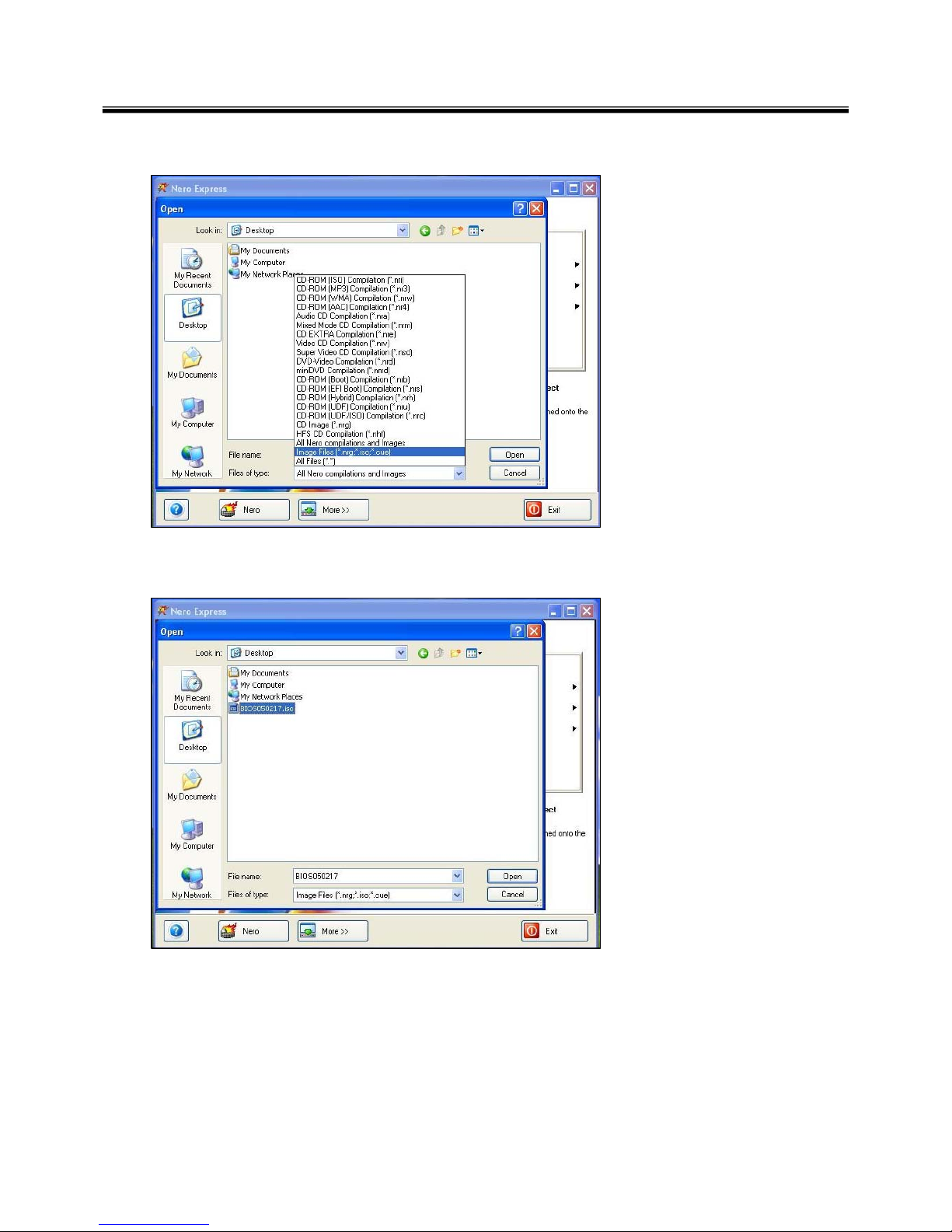
c. Select File Format as "Image Files(*.iso)".
d. Open Image File(*.iso) which is sent from LGE
Page 26
25
Ch3. System information
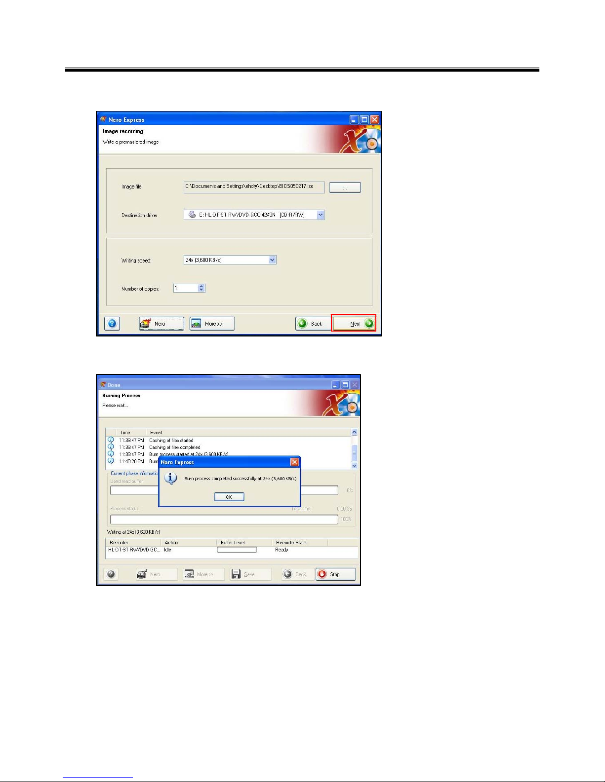
e. Tab Next then burning will be started
f. Burn process completed as below, and tab “OK”
Page 27
26
Ch3. System information
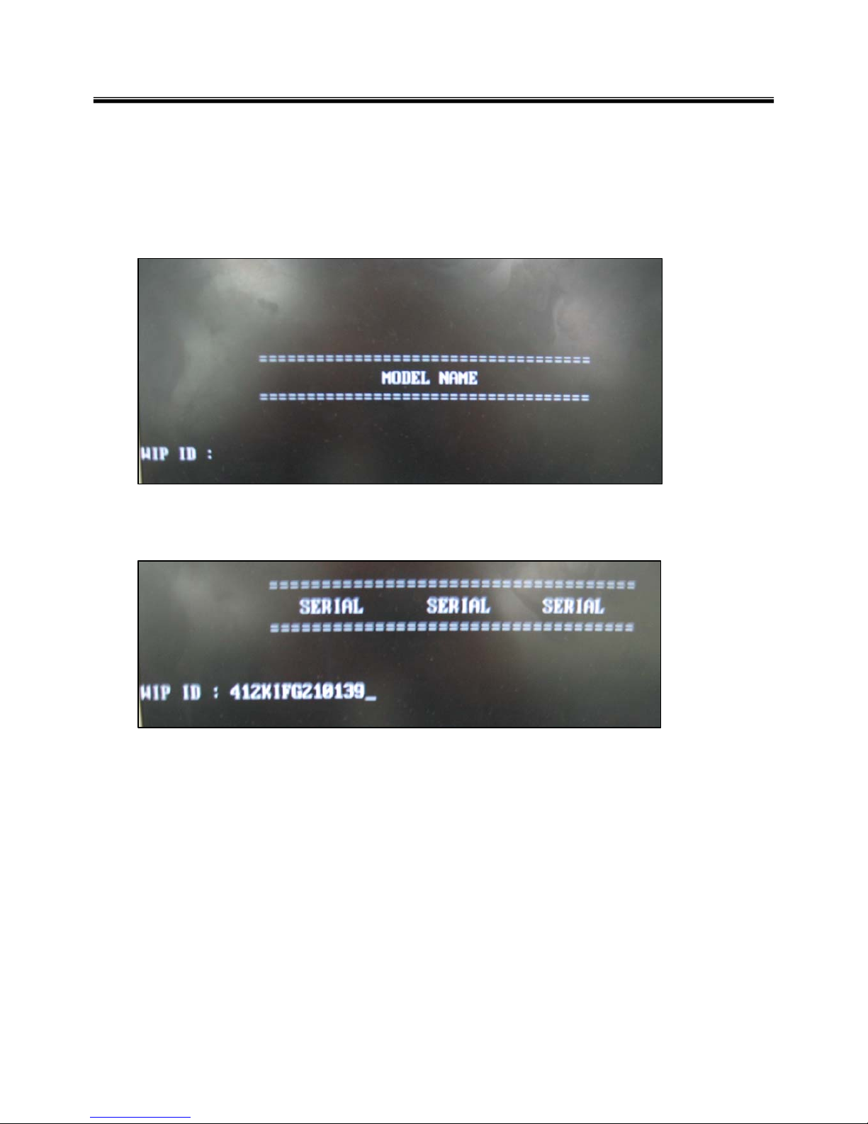
BIOS/EC Flash Process
1. Insert Bootable CD in PC, and Turn it on, then PC will boot by DOS mode as below
(If the EC is not correct or old version, then automatically update EC first and reboot again)
2. Type in Mode Name at the “WIP ID :” then press Enter key (You must use Capital Letter)
(You can see the Model Name in ID Label at the bottom Case of PC: “M/N: LMXX-XXXX”)
3. Type in Serial No at the “WIP ID :” then press Enter key (You must use Capital Letter)
(You can see the Serial No in ID Label at the bottom Case of PC: “S/N: 412KIXXXXXXXX”(13digits))
Page 28
27
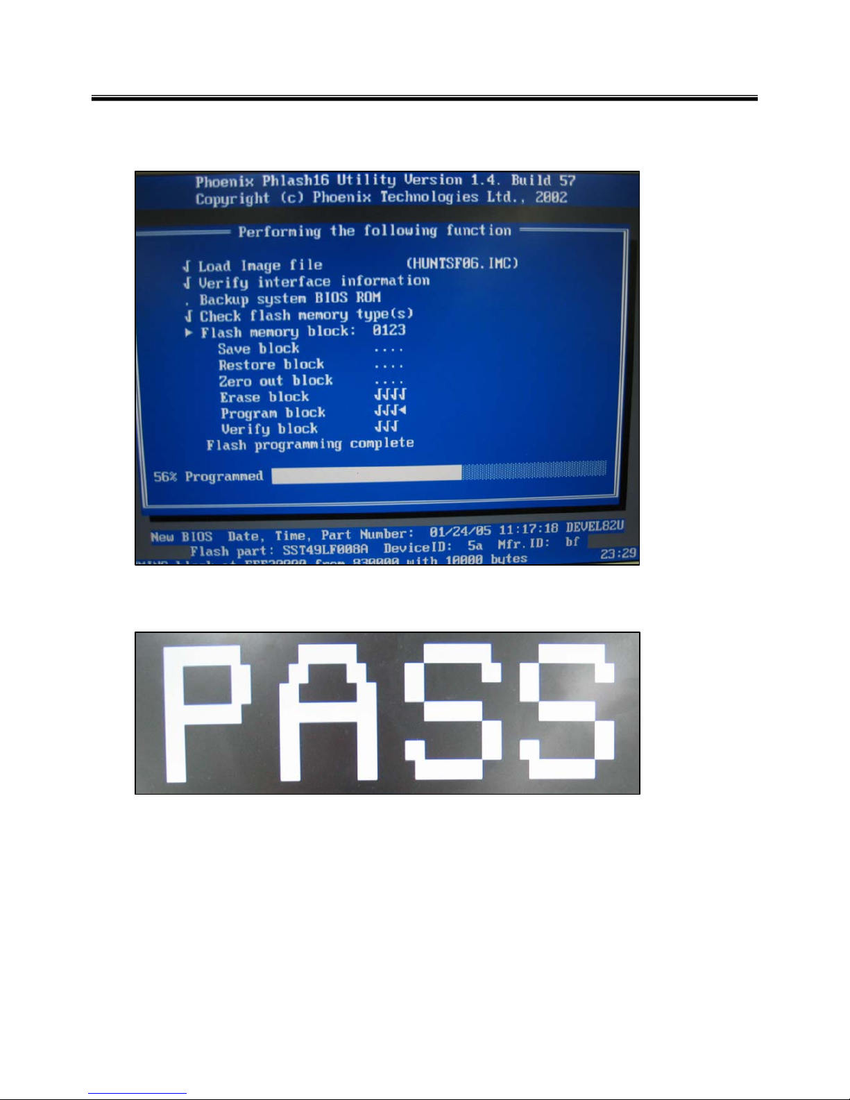
Ch3. System information
4. You can see the BIOS flash process as below
5. After flashing is completed, you can see the “PASS” on your screen, and reboot your PC
Page 29

28
BIOS Setup
BIOS (Basic Input and Output System) Setup saves the system configuration in CMOS RAM, and
check the configurations during startup. Use the BIOS Setup Utility to change and save the system
environment, hardware configurations, power saving mode, etc.
· Open the BIOS Setup Utility in the following situations :
1. to change the BIOS setup
2. to replace the backup battery
3. system configuration error occurs
4. to change the boot order
5. to set/change a password
Press the power button.
When the LG logo appears on the screen, press and enter the BIOS Setup Utility.
Ch3. System information
Page 30

29
Using the keys
The keys used in the BIOS Setup Utility and their functions are described at the bottom.
· , + : General Help
Display the descriptions of the keys used in the setup utility.
· , : Select Item
Navigate and select items in the setup utility. The selected item becomes highlighted.
· , : Select Menu
Move to another menu.
· / , : Change Values
Change the value of a selected item.
· : Load Default Configuration
Display Setup Confirmation window. Press Enter to load default configuration.
· : Select Sub-Menu
Some items have sub-menus. Display the sub-menu for a selected item.
· : Save and Exit
Display Setup Confirmation window. Press Enter to save and exit.
·: Exit
In a sub-menu, press Esc to move to the previous window. In Main menu, click Esc to move to Exit menu.
Ch3. System information
Page 31

30
Main menu
Show System Overview information about BIOS version, CPU features, Memory size and setting of
System Time and Date.
Advanced menu
Configure IDE and USB settings.
Boot menu
Set up Boot Type and Boot Sequence
Ch3. System information
BIOS Setup Menu
Once you enter the BIOS Setup Utility, the Main menu will appear on the screen.
The main menu displays the system information, including the basic configuration.
Page 32

31
Ch3. System information
Security menu
Install or clear Supervisor’s and User’s Password settings.
Exit menu
Choose decided status before leaving the BIOS menu.
Page 33

32
Main menu
Ch3. System information
System Overview
System Overview will show you BIOS version and other information about its build date and update notes. Following
is CPU’s information about its Type and Speed.
System Time
This item allows you to set the system time. The system clock will go on no matter you shut down the PC or get into
sleep mode. The set format is [hour:minute:second].
System Date
This item allows you to set the system date. The date format is [day:month:date:year].
Day: Day of the week, from Sun to Sat, which is determined by BIOS (read-only).
Month: The month from 01 (January) to 12 (December).
Date: The date from 01 to 31.
Year: The year can be adjusted by users.
Page 34

33
Advanced menu
Ch3. System information
Primary IDE Master/ Slave
The two items display the types of the primary master/slave IDE devices installed in the Notebook. Press [Enter] to
bring up a window showing the detailed information of the device, including the device name, vendor, LBA mode,
PIO mode and more.
Legacy USB Support
Select Enabled to enable the legacy support for USB devices. Setting options: Enabled, and Disabled.
Intel(R) SpeedStep(tm) tech.
This item allows you to enable or disable Intel SpeedStep technology. When set to Disabled, the system always
operates in a conserve power mode (the processor works at FSB400-600MHz or FSB533-800MHz). If you want
optimize the processor, set this item to Enabled, so that the processor’s speed will be controlled by the use of your
operating system and applications. Setting options: Enabled, and Disabled.
Page 35

34
Quiet Boot
This item enables you to show the vendor logo on the boot-up screen.
Settings options: Disabled and Enabled. The default setting is Enabled.
1st, 2nd and 3rd Boot Device
The three items allow you to set the sequence of boot devices where BIOS attempts to load the disk
operating system.
Ch3. System information
Boot menu
Page 36

35
Change Supervisor Password
Set supervisor password.
Change User Password
Set user password.
Security menu
Ch3. System information
Page 37

36
Exit Options
Save Changes and Exit
Save the changes you have made and exit the utility.
Discard Changes and Exit
Exit the utility without saving the changes you have made.
Discard Changes
Abandon your changes and reload the previous configuration before running the utility.
Load Optimal Defaults
Select this item to load the default settings for optimal system performance.
Exit menu
Ch3. System information
Page 38

37
Note
If replacing a part (FRU) does not solve the problem, put the original part back in the computer.
Do not replace a non-defective FRU.
The symptom-to-part index in this section lists symptoms and errors and their possible causes.
The most likely cause is listed first.
Power system checkout
· To verify a symptom, do the following :
1. Power off the computer.
2. Remove the battery pack.
3. Connect the AC adapter.
4. Check that power is supplied when you power on the computer.
5. Power off the computer.
6. Disconnect the AC adapter and install the charged battery pack.
7. Check that the battery pack supplies power when you power on the computer.
· If you suspect a power problem, see the appropriate one of the following power supply checkouts :
1. Checking the AC adapter
2. Checking the operational charging
3. Checking the battery pack
4. Checking the backup battery
· Checking the AC adapter
If the power-on indicator does not turn on, check the power cord of the AC adapter for correct continuity
and installation.
If the computer does not charge during operation, go to “Checking operational charging.”
Chapter 4. Symptom-to-part index
Ch4. Symptom-to-part index
Page 39

38
To check the AC adapter, do the following :
1. Unplug the AC adapter cable from the comput er.
2. Measure the output voltage at the plug of the
AC adapter cable. See the following figure :
3. If the voltage is not correct, remove the power code
form AC adapter.
4. 10 seconds later, connect the power code, then measure the output voltage.
5. If the voltage is not correct, change the AC adapter.
2
1
Ground2
+18.05 ~ +19.951
Voltage (V dc)Pin
Ch4. Symptom-to-part index
Page 40

39
· If the voltage is not correct, replace the AC adapter.
· If the voltage is acceptable, do the following :
1. Replace the system board.
2. If the problem persists, check the AC adapter whether it is correct product or not.
· Checking operational charging
1. To check whether the battery charges properly during operation, use a discharged battery pack or a
battery pack that has less than 50% of the total power remaining when installed in the computer.
Perform operational charging. If the battery status indicator or icon does not turn on, remove the battery
does not turn on, replace the battery pack.
2. If the charge indicator still does not turn on, replace thesystem board.
Then reinstall the battery pack.
Note
Noise from the AC adapter does not always indicate a defect.
Note
Do not charge battery pack, when its temperature is below 0 or above 75 .
· Checking the battery pack
1. Open the Power Meter window by clicking Start Control Panel Power Options and then;
check the total power remains. Battery charging does not start until the power Meter shows that less
than 95% of the total power remains; under this condition the battery pack can charge to 100% of its
capacity. This protects the battery pack from being overcharged or from having a shortened life.
2. To check the status of your batter, move your cursor to the Power Meter icon in the icon tray of the
Windows taskbar and wait for a moment (but do not click), and the percentage of battery power
remaining is displayed. To get detailed information about the battery, double-click the Power Meter icon.
Note
If the battery pack becomes hot, it may not be able to charge. Remove it from the computer and
Leave it at room temperature for a while. After it cools down, reinstall and recharge it.
Ch4. Symptom-to-part index
Page 41

40
· The Characteristics of the battery pack
1. Self-discharge
The battery gradually loses its power over time without ever being used.
2. Periodic full discharge / charge
Frequent recharge of the battery pack can reduce the capacity of the battery pack. When this happens,
you can perform the full discharge / charge to improve the capacity. You should perform periodic full
discharge /charge once every 30~60 days.
You should always use the battery until its power is low; then fully charge the battery.
3. Trickle charge
If the temperature of the battery pack drops below 10 , the trickle charging begins.
The trickle charging may take 32 hours for the battery pack to be fully charged.
Ch4. Symptom-to-part index
Page 42

41
· To check the battery pack, do the following :
1. Power off the computer.
2. Remove the battery pack and measure the voltage between battery terminals 1(-) and 5(+).
See the following figure :
Ground(-)8,9
+0V ~ +12.6V
(6 cell)
1,2
Voltage (V dc)Terminal
Note
Charging will take at least 3 hours.
3. If the voltage is still less than +11.1 V DC after recharging, replace the battery.
4. If the voltage is more than +11.1 V DC, measure the resistance between battery terminals 1 and 2.
The resistance must be 2 to 4 (typically 3 ).
5. If the resistance is not correct, replace the battery pack. If the resistance is correct, replace the system
board.
Ch4. Symptom-to-part index
Note
Battery is an expendable supplier, so its capacity and used time can be reduced by using the computer.
9(-)
432(+)
1(+)
8(-)
75
6
Page 43

42
LCD Breakdown NBL10
LCD Panel Scrape NBL09
LCD Display Ripple NBL08
LCD Output Color is incorrect NBL07
LCD Display Garbage NBL06
LCD Output Color Is Not Even NBL05
Dark Dot On LCD Panel NBL04
Bright Dot On LCD Panel NBL03
LCD Display Abnormally NBL02
LCD Flash NBL01
LCD Issue
System Auto Power Off NBP10
System Auto Power On NBP09
Can't Power Off NBP08
System Can't Shutdown Properly NBP07
No Display NBP06
System Hang Up In BIOS Utility NBP05
System Hang Up In POST NBP04
System Hang Up During Booting NBP03
System Can't Power On NBP02
No Power NBP01
System / Power Issue
Others NB999
NTF From Customer Return NB998
No Trouble Found
DOA NBDOA
Product Issue
English Description Code
Ch4. Symptom-to-part index
Repair Error Code
Page 44

43
HDD Performance Too LooNBH07
HDD Can't Create Partiti on NBH06
HDD Read / Write Error NBH05
HDD's Capacity Is Incorrect NBH04
HDD Breakdown NBH03
HDD Has Noise During Accessing Data NBH02
System Can't Detect HDD NBH01
HDD Issue
CD-ROM Vibrate Seriously While Rotating NBC08
CD Disc Comparability NBC07
CD-ROM Breakdown NBC06
CD-ROM Function Fail NBC05
CD-ROM Write Error NBC04
CD-ROM Read Error NBC03
CD-ROM Tray Can't Be Rejected NBC02
System Can't Detect CD-ROM Drive NBC01
ODD Issue
English Description Code
CPU Socket Fail NBCP3
CPU Breakdown NBCP2
CPU Speed Display Incorrectly NBCP1
CPU Issue
Memory Slot Fail NBD04
DRAM Breakdown NBD03
System Can't Detect DRAM Module NBD02
DRAM Size Display Incorrectly NBD01
SO-DIMM Issue
Ch4. Symptom-to-part index
Page 45

44
Touchpad Button Function Fail NBT04
Touchpad Surface Damage NBT03
Touchpad Can't Work NBT02
System Can't Detect Touchpad NBT01
Touchpad Issue
Keyboard Breakdown NBK04
Keyboard Button Drop Out NBK03
Keyboard Button Function Fail NBK02
Keyboard Can't Work NBK01
Keyboard Issue
Can't Power On When Use Battery Only NBB08
Battery Electric Leakage NBB07
Battery Capacity Display Abnormally In OS NBB06
Battery Life Is Too Short NBB05
Battery Breakdown NBB04
Battery's Capacity Will Down To Empty Quickly NBB03
Battery Pack Can't Charge To 100% NBB02
Battery Pack Can't Charge NBB01
Battery Pack Issue
PCMCIA Function Fail NBI12
Card Reader Function Fail NBI11
IEEE 1394 Port Function Fail NBI10
The TV Output Color Is Monochromatic NBI09
S-Video <TV-Out> Port Function Fail NBI08
VGA Port Function Fail NBI07
LPT Port Function Fail NBI06
USB Port Function Fail NBI05
Audio Volume Problem NBI04
Audio Noise NBI03
Internal Subwoofer Speaker Fail NBI02
Internal L/R Speaker Fail NBI01
I/O Issue
English Description Code
Ch4. Symptom-to-part index
Page 46

45
RJ45 Jack Pin Bending NBI40
Blue Tooth Function Fail NBI39
LCM Display Abnormally NBI38
DVD Region Code Error NBI37
CPU Fan Fail NBI36
System Or NB Temperature Is Too Hig h NBI35
Remote Controller Function Fail NBI34
Audio DJ Button Function Fail NBI33
Lid Switch Function Fail NBI32
AC Adapter Connector Fail NBI31
Status Indicator LED Fail NBI30
Quick Lanch Buttons <Instant Key> Function Fail NBI29
Connect Quality Is Unstable Via WLAN NBI28
Can't Connect To Internet Via WLAN NBI27
Wireless LAN Signal Is Weak Or Unstable NBI26
Wireless LAN Function Fail NBI25
Connect Quality Is Unstable Via RJ45 LAN Port NBI24
Can't Connect To Internet Via RJ45 LAN Port NBI23
MAC Address Is Empty NBI22
RJ45 <Network> Jack Function Fail NBI21
RJ11 <MODEM> Jack Function Fail NBI20
SPDIF-Out Function Fail NBI19
Line-In Jack Function Fail NBI18
Earphone-Out Jack Function Fail NBI17
Built-In MIC Function Fail NBI16
MIC-In Jack Function Fail NBI15
IrDA <Infaraed> Function Fail NBI14
PCMCIA Eject Switch Breakdown NBI13
I/O Issue
English Description Code
Ch4. Symptom-to-part index
Page 47

46
Can't Recovery System Use Recovery CD NBS10
System Hang Up After Update Hardware Driver NBS09
System Random Hang Up NBS08
Bundle Software Problem NBS07
Take Too Long To Resume From S4 NBS06
Take Too Long To Resume From S3 NBS05
Take Too Long To Enter In OS NBS04
Can't Install OS NBS03
OS (XP / 2000) Loading Fail NBS02
Microsoft Issue (Setting / Bug) NBS01
OS / Software / Driver Issue
System Can't Boot After Flash KBC Firmware NBFB8
System Can't Boot Result From Flash BIOS Fail NBFB7
System Can't Boot After Flash BIOS NBFB6
KBC Firmware Version Error NBFB5
Flash KBC Firmware Fail NBFB4
Can't Flash BIOS NBFB3
BIOS Version Error NBFB2
Flash BIOS Fail NBFB1
BIOS Issue
English Description Code
Ch4. Symptom-to-part index
Page 48

47
Change A/B/C/D Casing Or Other Mechanism Parts NBUP6
Change Keyboard Language NBUP5
WLAN Module Upgrade NBUP4
So-Dimm Upgrade NBUP3
HDD Upgrade NBUP2
CPU Upgrade NBUP1
HW / ME Parts Upgrade Issue
Sticker Loose Or Damage NBM10
AC Adapter Damage NBM09
OSD Bezel Damage NBM08
Palm Rest Damage NBM07
Hinge Cover Damage NBM06
Middle Cover Damage NBM05
Lower Case (D Casing) Damage NBM04
Top Case (C Casing) Damage NBM03
LCD Bezel (B Casing) Damage NBM02
LCD Cover (A Casing) Damage NBM01
Mechanism / Accessory Parts Issue
Ch4. Symptom-to-part index
Page 49

48
System is unstable After Install Not Suitable SoftwareNBR29
Customer's Device Is Poor Comparability With NBNBR28
Reinstall OSNBR27
Update KBC FirmwareNBR26
Incorrect Operation By CustomerNBR25
CPU Fan DamageNBR24
Remote Controller DamageNBR23
Wireless LAN Module DamageNBR22
Wireless LAN Antenna DamageNBR21
HW Driver IncorrectNBR20
Touchpad Cable DamageNBR19
Keyboard Cable DamageNBR18
Battery Connector FailNBR17
Socket / Slot DamageNBR16
CD-ROM Doesn't Fix To NBNBR15
Inverter Cable DamageNBR14
Inverter DamageNBR13
Connector DamageNBR12
LVDS Cable DamageNBR11
SWAP New TouchpadNBR10
SWAP New KeyboardNBR09
SWAP New Battery PackNBR08
SWAP New WLAN ModuleNBR07
SWAP New CPUNBR06
SWAP New DRAM ModuleNBR05
SWAP New OSDNBR04
SWAP New HDDNBR03
SWAP New LCD PanelNBR02
DOA Return And Change New ProductNBR01
No Component, Replace MainboardNBMB2
Replace, SWAP MainboardNBMB1
No Problem FoundNBN01
English DescriptionCode
Ch4. Symptom-to-part index
Repair RMA Code
Page 50

49
ReworkNBREW
Re-Paste New StickerNBR37
SWAP New PCMCIA BracketNBR36
SWAP New Mechanism PartsNBR35
Blue Tooth Antenna DamageNBR34
SWAP New Blue Tooth ModuleNBR33
SWAP New AC AdapterNBR32
Update BIOSNBR31
CPU / VGA Thermal Module Or Thermal Pad DamageNBR30
English DescriptionCode
Ch4. Symptom-to-part index
Page 51

50
Indeterminate problems
· You are here because the diagnostic tests did not identify which adapter or device failed, wrong devices
are installed, a short circuit is suspected, or the system is inoperative.
Follow these procedures to isolate the failing FRU (do not isolate FRUs that have no defects).
· Verify that all attached devices are supported by the computer.
· Verify that the power supply being used at the time of the failure is operating correctly.
1. Power off the computer
2. Visually check each FRU for damage. Replace any damaged FRU.
3. Remove or disconnected all of the following devices :
a. Non-LG devices.
b. Printer, mouse, and other external devices.
c. Battery pack.
d. PC cards.
e. ODD (CD-ROM, Combo) drive or FDD drive in the Bay.
f. Hard-disk drive.
Note
Use the other memory card because it needs when operating computer.
4. Power on the computer.
5. Determine whether the problem has changed.
6. If the problem does not recur, reconnect the removed devices one at a time until you find the failing FRU.
7. If the problem remains, replace the following FRUs one at a time.
(do not replace a non-defective FRU)
a. LCD assembly (Check external monitor whether the same problem recurs or not).
b. Keyboard.
c. Keydeck (TouchPad and Scroll Button assembly).
d. System board.
Ch4. Symptom-to-part index
Page 52

51
Chapter 5. Removing and replacing a part (FRU)
Note
As for the screw, every Torque 3 0.2Kgfcm(0.196Nm)
Danger
Before removing any FRU, power off the comput er, u npl u g all po we r co rds from elect rical
outlets, remove the battery pack, and then disconnect any interconnecting cables.
Caution
Before the computer is powered on after FRU replacement, make sure that all screws, springs,
and other small parts are in place and are not loose inside the computer. Verify metal flakes can
cause electrical short circuits.
Ch5. Removing and replacing a part
Page 53

52
■ 1010 Battery Pack
1. Push the battery latch in the direction shown below; then slide the battery pack out of the slot.
Ch5. Removing and replacing a part
Page 54

53
2M2.5X0.45P,4.5mm,
5mm
FAB300651011
QtySpecificationFRU No.No.
1. Remove 2 Screws the, remove the HDD Cover.
2. Remove the HDD Cushion.
■ 1020 Hard Disk Drive
Ch5. Removing and replacing a part
※ Remove the following parts in order before replacing this part
a. Battery Pack(1010)
Page 55

54
3. Remove HDD Assembly.
4. Remove 2 Screws.
2M2X0.4,4.5mm,3mmFAB300655011
QtySpecificationFRU No.No.
Ch5. Removing and replacing a part
Page 56

55
Ch5. Removing and replacing a part
Page 57

56
3
M2.5X0.45P,4.5mm,
5mm
FAB300651011
QtySpecificationFRU No.No.
1. Remove 4 Screws.
2. Remove the System Door.
Ch5. Removing and replacing a part
■ 1020 Hard Disk Drive
※ Remove the following parts in order before replacing this part
a. Battery Pack(1010) b. Hard Disk Drive(1020)
Page 58

57
3. Remove the Memory Module.
Ch5. Removing and replacing a part
Page 59

58
1. Remove a Screw.
2. Remove the Optical Disk Drive.
1M2.5X0.45P,4.5mm,
5mm
FAB300651011
QtySpecificationFRU No.No.
Ch5. Removing and replacing a part
■ 1040 Optical Disk Drive
※ Remove the following parts in order before replacing this part
a. Battery Pack(1010) b. Hard Disk Drive(1020) c. Memory(1030)
Page 60

59
1. Remove a Screw, then disconnect the Antenna Cable.
2. Remove the WLAN Card.
Ch5. Removing and replacing a part
■ 1050 WLAN Card
※ Remove the following parts in order before replacing this part
a. Battery Pack(1010) b. Hard Disk Drive(1020) c. Memory(1030) d. Optical Disk Drive(1040)
Page 61

60
1. Remove 2 Screws, then disconnect the MDC Connector.
2. Remove the MDC Card.
Ch5. Removing and replacing a part
■ 1060 MDC Card
※ Remove the following parts in order before replacing this part
a. Battery Pack(1010) b. Hard Disk Drive(1020) c. Memory(1030) d. Optical Disk Drive(1040)
e. WLAN Card(1050)
Page 62

61
1. Remove 5 Screws.
5M2.5X0.45P,4.5mm,
5mm
FAB300651011
QtySpecificationFRU No.No.
2. Disconnect the Fan Assembly Cable, then remove the Fan Assembly.
Ch5. Removing and replacing a part
■ 1070 Fan Assembly
※ Remove the following parts in order before replacing this part
a. Battery Pack(1010) b. Hard Disk Drive(1020) c. Memory(1030) d. Optical Disk Drive(1040)
e. WLAN Card(1050) f. MDC Card(1060)
Page 63

62
Ch5. Removing and replacing a part
Page 64

63
1. Remove 3 Hooks.
2. Remove the Retainer.
Ch5. Removing and replacing a part
■ 1080 Retainer
※ Remove the following parts in order before replacing this part
a. Battery Pack(1010) b. Hard Disk Drive(1020) c. Memory(1030) d. Optical Disk Drive(1040)
e. WLAN Card(1050) f. MDC Card(1060) g. Fan Assembly(1070)
Page 65

64
Ch5. Removing and replacing a part
Page 66

65
1. Remove 5 Screws.
2. Disconnect the Keyboard Connector.
5M2X0.4,4.5mm,3mmFAB300655011
QtySpecificationFRU No.No.
Ch5. Removing and replacing a part
■ 1090 Keyboard
※ Remove the following parts in order before replacing this part
a. Battery Pack(1010) b. Hard Disk Drive(1020) c. Memory(1030) d. Optical Disk Drive(1040)
e. WLAN Card(1050) f. MDC Card(1060) g. Fan Assembly(1070) h. Retainer(1080)
Page 67

66
3. Remove the Keyboard.
Ch5. Removing and replacing a part
Page 68

67
1. Remove 3 Screws.
3M2.5X0.45P,4.5mm,
5mm
FAB300651011
QtySpecificationFRU No.No.
2. Disconnect the Button Sub Board Connector.
Ch5. Removing and replacing a part
■ 1090 Keyboard
※ Remove the following parts in order before replacing this part
a. Battery Pack(1010) b. Hard Disk Drive(1020) c. Memory(1030) d. Optical Disk Drive(1040)
e. WLAN Card(1050) f. MDC Card(1060) g. Fan Assembly(1070) h. Retainer(1080)
i. Keyboard(1090)
Page 69

68
3. Remove the Button Sub Board.
Ch5. Removing and replacing a part
Page 70

69
1. Disconnect the LCD Connector and Inverter Connector.
Ch5. Removing and replacing a part
■ 1110 Display Module
※ Remove the following parts in order before replacing this part
a. Battery Pack(1010) b. Hard Disk Drive(1020) c. Memory(1030) d. Optical Disk Drive(1040)
e. WLAN Card(1050) f. MDC Card(1060) g. Fan Assembly(1070) h. Retainer(1080)
i. Keyboard(1090) j. Button Sub Board(1100)
Page 71

70
2. Remove 2 Screws.
2M2.5X0.45P,4.5mm,
5mm
FAB300651011
QtySpecificationFRU No.No.
3. Remove 2 Screws.
2M2.5X0.45P,4.5mm,
5mm
FAB300651011
QtySpecificationFRU No.No.
Ch5. Removing and replacing a part
Page 72

71
4. Remove the Display Module.
Ch5. Removing and replacing a part
Page 73

72
1. Disconnect the Touchpad Connector.
2. Remove the PCMCIA Dummy Card and the SD Dummy Card.
Ch5. Removing and replacing a part
■ 1120 Main Board
※ Remove the following parts in order before replacing this part
a. Battery Pack(1010) b. Hard Disk Drive(1020) c. Memory(1030) d. Optical Disk Drive(1040)
e. WLAN Card(1050) f. MDC Card(1060) g. Fan Assembly(1070) h. Retainer(1080)
i. Keyboard(1090) j. Button Sub Board(1100) k. Display Module(1110)
Page 74

73
3. Remove 17 Screws.
2M2.5X0.45P,4.5mm
,5mm
FAB300651011
QtySpecificationFRU No.No.
4. Remove the Bottom Case.
Ch5. Removing and replacing a part
Page 75

74
4. Remove a Screw.
1M2.5X0.45P,4.5mm,
5mm
FAB300651011
QtySpecificationFRU No.No.
Ch5. Removing and replacing a part
Page 76

75
5. Remove the Main Board.
Ch5. Removing and replacing a part
Page 77

76
1. Remove a Screw.
1M2.5X0.45P,4.5mm,
5mm
FAB300651011
QtySpecificationFRU No.No.
2. Remove the Speaker Cable.
Ch5. Removing and replacing a part
■ 1130 Main Board
※ Remove the following parts in order before replacing this part
a. Battery Pack(1010) b. Hard Disk Drive(1020) c. Memory(1030) d. Optical Disk Drive(1040)
e. WLAN Card(1050) f. MDC Card(1060) g. Fan Assembly(1070) h. Retainer(1080)
i. Keyboard(1090) j. Button Sub Board(1100) k. Display Module(1110) l. Main Board(1120)
Page 78

77
3. Remove a Screw.
1M2.5X0.45P,4.5mm,
5mm
FAB300651011
QtySpecificationFRU No.No.
2. Remove the Speakers.
Ch5. Removing and replacing a part
Page 79

78
1. Disconnect the Microphone Connector, then remove the Microphone.
Ch5. Removing and replacing a part
■ 1140 Microphone
※ Remove the following parts in order before replacing this part
a. Battery Pack(1010) b. Hard Disk Drive(1020) c. Memory(1030) d. Optical Disk Drive(1040)
e. WLAN Card(1050) f. MDC Card(1060) g. Fan Assembly(1070) h. Retainer(1080)
i. Keyboard(1090) j. Button Sub Board(1100) k. Display Module(1110) l. Main Board(1120)
Page 80

79
1. Remove a Screw.
1M2.5X0.45P,4.5mm,
5mm
FAB300651011
QtySpecificationFRU No.No.
Ch5. Removing and replacing a part
■ 1150 USB Sub Board
※ Remove the following parts in order before replacing this part
a. Battery Pack(1010) b. Hard Disk Drive(1020) c. Memory(1030) d. Optical Disk Drive(1040)
e. WLAN Card(1050) f. MDC Card(1060) g. Fan Assembly(1070) h. Retainer(1080)
i. Keyboard(1090) j. Button Sub Board(1100) k. Display Module(1110) l. Main Board(1120)
Page 81

80
3. Remove the USB Sub Board.
2. Disconnect the USB Sub Board Connector.
Ch5. Removing and replacing a part
Page 82

81
1. Using a knife, remove the rubbers that are covering screws. Then remove 8 Screws.
8M2.5X0.45P,4.5mm,
5mm
FAB300651011
QtySpecificationFRU No.No.
Ch5. Removing and replacing a part
■ 1160 Display Exploded View
※ Remove the following parts in order before replacing this part
a. Battery Pack(1010) b. Hard Disk Drive(1020) c. Memory(1030) d. Optical Disk Drive(1040)
e. WLAN Card(1050) f. MDC Card(1060) g. Fan Assembly(1070) h. Retainer(1080)
i. Keyboard(1090) j. Button Sub Board(1100) k. Display Module(1110)
Page 83

82
3. Remove 2 Screws, then remove the LCD Hinges.
2. Remove the Front Case.
2M2.5X0.45P,4.5mm,
5mm
FAB300651011
QtySpecificationFRU No.No.
Ch5. Removing and replacing a part
Page 84

83
5. Remove the LCD.
4. Remove 2 Screws.
2M2.5X0.45P,4.5mm,
5mm
FAB300651011
QtySpecificationFRU No.No.
Ch5. Removing and replacing a part
Page 85

84
7. Remove the WLAN Antenna.
6. Remove the Bracket, then remove 4 Screws.
4M2.5X0.45P,4.5mm,
5mm
FAB300651011
QtySpecificationFRU No.No.
Ch5. Removing and replacing a part
Page 86

85
8. Disconnect the LCD Cable and the Inverter Connector.
Ch5. Removing and replacing a part
Page 87

86
9. Remove 8 Screws, then remove LCD Bracket.
8M2X0.4,4.5mm,3mmFAB300655011
QtySpecificationFRU No.No.
Ch5. Removing and replacing a part
Page 88

87
REV.04
,SYS/POWER SUPPLY ADAPTOR/90W/90-264Vin/4.74A/19Vout/LI SHIN/LSE0202C1990/FOR MS1037,RoHS COMPLIANCE
EAY32531401NACA1
,SYS/BATTERY PACK/LITHIUMION/SMP/925C2450F/PANASONIC/3.6V/2200mAh/6cells/10.8V/4400mAH/18650/BLACK/FOR SQU524,RoHS COMPLIANCE
EAC32576901 NBATM
2200mAhEAC32576902NBATM
,SYS/MODULE/INVERTER/SAMPO/ YIVNMS0020D11--/FOR AU AND LG 15inch PANEL/FOR MS1034L1,RoHS COMPLIANCE
EAY32711501NNVE1
TS64MSQ64V5J 0IMMR00233BNMEM1
TS64MSQ64V6JEAN33410401NMEM1
,SYS RAM MODULE,DDR2
SDRAM,333(667)MHz,512MB,SODIMM,TRANSCEND/TS64MSQ64V6J,64MX64bit/1.8V/HYNIX
CHIP,RoHS COMPLIANCE
EAN32932101NMEM1
,SYS RAM MODULE,DDR2 SDRAM,333(667)MHz,512MB,SODIMM,TWINMOS/8D23JN5JEATP,64MX64bit/1.8V/ELPIDA CHIP,RoHS COMPLIANCE
EAN32872001NMEM1
ASSY(bezel
+bracket)
??? /HLDS/GCC-4244N, S74-1303090-H44ABQ31509002NODD1
ASSY(bezel
+bracket)
Active,MS-16121L1,Black,Super-Multi,,FOR HLDS, S7A-1322010-H44ABQ31509001NODD1
BUY&SELL/LG,SYS/HDD/SATA-150/HITACHI/HTS541010G9SA00/2.5 inch/100GB/5400RPM/FOR MS1034L1,RoHS COMPLIANCE
6744C00158BNHDD1
80GB;5400rpm (RoHS)6744C00147CNHDD1
60GB;5400rpm (RoHS)6744C00146CNHDD1
BUY&SELL/LG,SYS/HDD/SATA-150/2.5 inch/100GB/5400RPM/FUJITSU/MHV2100BH/FOR MS 1034L1,RoHS COMPLIANCE
6744C00157ANHDD1
80GB;5400rpm (RoHS)6744C00156ANHDD1
60GB;5400rpm (RoHS)6744C00155ANHDD1
15.4" WXGA( Glare,RoHS type)6304FLP155ENLCD1
CPU Merom (Napa refresh) Intel 1.66GHZ Cache 2MB 667MHZ FCPGA-478pinEAN32961201NCPU1
CPU Merom (Napa refresh) Intel 1.83GHZ Cache 2MB 667MHZ FCPGA-478pinEAN32960101NCPU1
Celeron 1.6G 533MHZ (QKIT)EAN32927801NCPU1
Celeron 1.73G 533 MHZ (QKIS) EAN31735101NCPU1
BUY&SELL/LG,CPU YONAH,INTEL/QPUD 1.73G,,1.73GHz,FCPGA-478pin,1MB 533MHz FSB DUO
CORE YONAH,RoHS COMPLIANCE
EAN32181401NCPU1
RemarksSpecificationPart NoLocation
Chapter 6. Part lists
Ch6. Part lists
Page 89

88
MS-1034LG-0323359AGR-X0(FOR 03083595)-GREEK-060703.pdfAEW31528401NKBD1
MS-1034LG-0323359ATQ-X0-TURKISH-060703.pdfAEW31528301NKBD1
,SYS KEYBOARD,LARGE,103KEY,Swedish,BLACK,CHICONY/MP-03233S0-359A,FOR L1,RoHS(EU
EXEMPTION)
AEW31528201NKBD1
MS-1034LG-0323359APA-X0-BRAZIL-060703.pdfAEW31528101NKBD1
MS-1034LG-0323359AP0-X0-PORTUGUESE-060703.pdfAEW31528001NKBD1
MS-1034LG-0323359AN0-X0-NORWAY-060628.pdfAEW31527901NKBD1
MS-1034LG-0323359AI0-X0-ITALY-060628.pdfAEW31527801NKBD1
MS-1034LG-0323359AHU-X0-HUNGARIAN-060628.pdfAEW31527701NKBD1
MS-1034LG-0323359AF0-X0-FRENCH-060628.pdfAEW31527401NKBD1
MS-1034LG-0323359AE0-X0-SPANISH-060628.pdfAEW31527301NKBD1
MS-1034G-0323359ADK-X0-DENMARK-0606703.pdfAEW31527201NKBD1
MS-1034LG-0323359AD0-X0-GERMAN-060628.pdfAEW31527101NKBD1
MS-1034LG-0323359ACK-X0-CANADA FRENCH-060628.pdfAEW31527001NKBD1
MS-1034LG-0323359AHB-X0-HEBREW-060628.pdfAEW31526901NKBD1
MS-1034LG-0323359AUS-X2-US-060628.pdfAEW31252901NKBD1
MS-1034LG-0323359AU4-X0-US INTERNATIONAL-060703.pdfAEW31526801NKBD1
MS-1034LG-0323359ASU-X0-RUSSIAN-0606703.pdfAEW31526701NKBD1
MS-1034LG-0323359ARC-X0-CHINESE-0606703.pdfAEW31526601NKBD1
MS-1034LG-0323359AK0-X0-KOREA-060628.pdfAEW31252701NKBD1
MS-1034LG-0323359AA0-X0-ARABIC-060628.pdfAEW31526501NKBD1
MS-10392T8 11 MS-10342 0B USB boardEBR32816601NSUBU
MS-10343 0B MS-1034(LG)switch/B 0B VersionEBR32816001NSUBB
ver 2.2 for 90W Power only, MS-10341 210 mainboard for MS-10341EBR32815601NMLB1
EBM32947101NLAN1
Wireless Lan mini card 802.11b/gEBM32946601NLAN1
6718M000033NLAN1
6718M000030NLAN1
6718M000029NLAN1
,SYS/MODULE/WIRELESS/INTEL/INTEL PRO W I RELESS 3945ABG/PCI EXPRESS MINI
CARD/SKU1(MOW1),RoHS COMPL IANCE
6718M000032NLAN1
3945ABG/PCI EXPRESS MINI CARD,RoHS COMPLIANCE6718M000031NLAN1
MDC(FACTOR AC97/AZALIA V.92 MODDEM CARD)/FOR MS-1039,RoHS COMPLIANCE (choke) 6871BG870AANMDM1
RemarksSpecificationPart NoLocation
Ch6. Part lists
Page 90

89
,MECH,USB MYLAR,MYLAR,33*21*0.15mm,,NB,FOR MS-16322,,RoHS COMPLIANCEMHK33716301NSETU
,MECH,SCREW,PLAT,CR O SS RECESS,M2.5X0.45P ,4.5mm,5mm,MACHINE SCREW,WITH
NYLOK,PLATING ZINC,BLACK,FOR MS-1004,AISI-1018,RoHS COMPLIANCE
FAB30065101NSCR1
,SYS/SPEAKER ASSY/SABLE/1.5W/2 SETS/FOR MS-1039,RoHS COMPLIANCEACQ31503601NSPK1
,SYS/MICROPHONE/SABLE/SENSITIVITY:-44 ±3dB/6.0ψ*2.7/FOR MS-1039,RoHS COMPLIANCEEAB33543401NMCP1
T/P B/D,INT FFC CABLE,,,6,126mm,0.5mm,FOLDING,FOR MS-1039,,RoHS COMPLIANCEEAD33352001NCAB2
button B/D,INT FFC CABLE,,,12,38mm,0.5mm,,FOR MS-1039,,RoHS COMPLIANCEEAD33351801NCAB1
MS1034 LG Top Case ModuleMBN33701101NCSEK
,MECH FANSINK,,CU,,SCREW-4,,,,,,,,,,W/PIPE/SOCKET 478,ROHS COMPLIANCEAGU31509301NFAN1
Wireless LAN Antenna cable-REAA32762801NANTR
Wireless LAN Antenna cable-LEAA32755001NANTL
3300BA4034ANSETF
,VER.00-,MECH,NB,ELECTROTYPE+ADHESIVE,LOGOBADGE FOR LG,17*0.5mm,FOR MS1016L1,,RoHS COMPLIANCE
3300BZ4107ANSETF
MBN33752804NCAPH
MBN33752803NCAPH
MBN33752802NCAPH
MS1034 LG Hinge Cover ASSY,RoHSCOMPLIANCEMBN33752801NCAPH
MBN33751602NCSER
MS1034 LG LCD Cover Assy,RoHSCOMPLIANCEMBN33752001NCSER
India type, RoHS6410BW21601NPCD1
Argentina6410BT21003NPCD1
Israel6410BV21003NPCD1
Korean type, RoHS6410BM21601NPCD1
Australia type, RoHS6410BK21007NPCD1
South Africa6410BU21602NPCD1
China6410BO20602NPCD1
ITALIAN6410BR21004NPCD1
Singapore / UAE (E1) / UK6410BH21003NPCD1
Germany, France, Poland, Hungary, Turkey, Norway, Sweden, Denmark, Finland, Greece, Spanish,
Purtogese, Tunisia, UAE (E5), Russia, Baltic, Ukraine
6410BD21602NPCD1
Canada / Columbia / Chile / Mexico6410BC11017NPCD1
RemarksSpecificationPart NoLocation
Ch6. Part lists
Page 91

90
ODD bezelMS1034 ODD Bezel ASSY for Supermulti,RoHSCOMPLIANCEABQ31509101NCVRD
,MECH,B FACE LOGO,ELECTRO-FORMING (NI),21.8*10.5mm,BLACK BACKGROUND WITH SILVER
TEXT (LG),NB,FOR All LG MODEL,,RoHS COMPLIANCE
AGU31509201NSETR
MS1039 HDD Bracket ASSY,RoHS COMPLIANCEABA31508901NBRKH
Active,Intel Yonah,QPUD-1.73G,Centrino Duo label,FORLG consign,3850BB4551ANLBLC
MS1039 HDD Door Assy,RoHS COMPLIANCEADC31508701NCVRH
MS 16323 Bottom Door Assy,RoHS COMPLIANCEMCV33752901NCVRB
,SYS/ANTENNA/YAGEO/LEFT/FOR MS-1039,RoHS COMPLIANCEEAA33377801NANTL
,SYS/ANTENNA/YAGEO/RIGHT/FOR MS-1039,RoHS COMPLIANCEEAA33377601NANTR
,MECH,LCD_BRACKET,SECC T=0.6mm,239.6*13.7mm,,NB,FOR MS-16322,,RoHS COMPLIANCEMAZ33752601NBRKL
,INT COAXIAL CABLE,30,182mm,MB-30pin/LCD-20pin,FOR MS-1039,LVDS CABLE,RoHS COMPLIANCEEAD33377501NCABL
MECH,LCD_HINGE_R,SK7+SUS,39*14mm,,NB,FOR MS-16311,,RoHS COMPLIANCEMEF33752301NHNGR
,MECH,LCD_HINGE_L,SK7+SUS,38*14.5mm,,NB,FOR MS-16312,,RoHS COMPLIANCEMEF33752101NHNGL
,MECH,LCD_REAR_BRACKET,SECC,,,NB,FOR MS-16121,,RoHS COMPLIANCEMAZ33751801NBRKR
,INT INVERTER CABLE,6,370mm,MB-6P/INVERTER-6P,FOR MS-1039,,RoHS COMPLIANCEEAD33377201NCABN
,MECH,MAGNET,ND-FE-B,13*3*5.6mm,,NB,FOR MS-16322,MODIFY FROM E22-1039070-SF7,RoHS
COMPLIANCE
MGJ33750701NPLTL
,MECH,LCD RUBBER-BUMPER,RUBBER,5.9*0.9mm,PANTONE COOL BLACK,NB,FOR MS16311&16322,,RoHS COMPLIANCE
MCQ33747001NRUBC
,MECH,SUPPORT_KB_RUBBER,RUBBER,13*10*2.5mm,BLACK,NB,FOR MS-16121,,RoHS
COMPLIANCE
MCQ33746901NRUBK
,MECH,HDD PORON,PORON SRS-48P,11*8*0.45mm,,NB,FOR MS-16161,,RoHS COMPLIANCEMCQ33746801NRUBP
,MECH,KB_MYLAR,MYLAR,170*5*0.1mm,BLACK,NB,FOR MS-16121,,RoHS COMPLIANCEMHK33746701NSETH
,MECH,HDD SPONGE,SPONGE,60*11*7mm,,NB,FOR MS-16161,,RoHS COMPLIANCEMCQ33746501NRUBS
MS1034 Channel_Low Case ASSY,RoHS COMPLIANCEMBN33746401NCSEB
,MECH,HDD_NRB,SPONGE,33*38*3mm,,NB,FOR MS-16121,BLACK,RoHS COMPLIANCEMCQ33746201NRUBH
,INT OTHER CABLE,ROUND/16/480mm/20P-10P+10P/FOR MS-1039,RoHS COMPLIANCEEAD33376501NCAB3
,INT OTHER CABLE,RJ11 MODEM CABLE/ROUND/2/290mm/HOUSING MOLEX:51021-0200/TERMINAL
MOLEX:50058-8200/FOR MS-1039,RoHS COMPLIANCE
EAD33376401NCABM
,MECH,SCREW,PLAT,CROSS RECESS,M2X0.4,4.5mm,3mm,MACHINE SCREW,WITH NYLOK,PLATED
NI,,FOR MS-1003,AISI-1018,RoHS COMPLIANCE
FAB30065501NSCR2
,MECH,CARD READER RUBBER,RUBBER,38.1*17*6.05mm,BLACK,NB,FOR MS-16312,,RoHS
COMPLIANCE
MCQ33720101NRUBR
,MECH,FRONT_BEZEL,PC,129.8*15.55mm,,NB,FOR MS-16311,,RoHS COMPLIANCEMBN33719901NCSEF
RemarksSpecificationPart NoLocation
Ch6. Part lists
Page 92

91
NBATM
NCVRB
NCVRH
NHDD1 NRUBS
NSCR1
Page 93

92
NODD1
NMEM1
NLAN1
NMDM1
NFAN1
Page 94

93
NKBD1
NCPU1
NMCP1
NSPK1 NSPK1
NMLB1
NSUBU
NSETR
NCAPH
NCABM
NCAB3
NRUBR
Page 95

94
NCSEK
NANTL
NANTR
NBRKR
NSCR2 NCAB1
Page 96

95
NSUBB
NCSEB
Page 97

96
NBRKH
NCSEF
NHNGL NHNGRNSETR
Page 98

97
NSETF
NCSER
NLCD1
NNVE1
NCABN
NCABL
NPLTL
Page 99

98
NBRKLNBRKL
NBRKL
 Loading...