

LG DU-50PZ60X Service Manual

PLASMA TV
SERVICE MANUAL
CAUTION
BEFORE SERVICING THE CHASSIS,
READ THE SAFETY PRECAUTIONS IN THIS MANUAL.
CHASSIS : AF-03BA
MODEL : DU-50PZ60/H
website:http://biz.LGservice.com
e-mail:http://www.LGEservice.com/techsup.html
- 2 -
SAFETY PRECAUTIONS
Many electrical and mechanical parts in this chassis have special safety-related characteristics. These parts are identified by in
the Schematic Diagram and Replacement Parts List.
It is essential that these special safety parts should be replaced with the same components as recommended in this manual to
prevent X-RADIATION, Shock, Fire, or other Hazards.
Do not modify the original design without permission of manufacturer.
General Guidance
An lsolation Transformer should always be used during
the servicing of a receiver whose chassis is not isolated from
the AC power line. Use a transformer of adequate power rating
as this protects the technician from accidents resulting in
personal injury from electrical shocks.
It will also protect the receiver and it's components from being
damaged by accidental shorts of the circuitary that may be
inadvertently introduced during the service operation.
If any fuse (or Fusible Resistor) in this monitor is blown, replace
it with the specified.
When replacing a high wattage resistor (Oxide Metal Film
Resistor, over 1W), keep the resistor 10mm away from PCB.
Keep wires away from high voltage or high temperature parts.
Due to high vacuum and large surface area of picture tube,
extreme care should be used in handling the Picture Tube.
Do not lift the Picture tube by it's Neck.
Leakage Current Cold Check(Antenna Cold Check)
With the instrument AC plug removed from AC source,
connect an electrical jumper across the two AC plug prongs.
Place the AC switch in the on positioin, connect one lead of
ohm-meter to the AC plug prongs tied together and touch other
ohm-meter lead in turn to each exposed metallic parts such as
antenna terminals, phone jacks, etc.
If the exposed metallic part has a return path to the chassis, the
measured resistance should be between 1MΩ and 5.2MΩ.
When the exposed metal has no return path to the chassis the
reading must be infinite.
An other abnormality exists that must be corrected before the
receiver is returned to the customer.
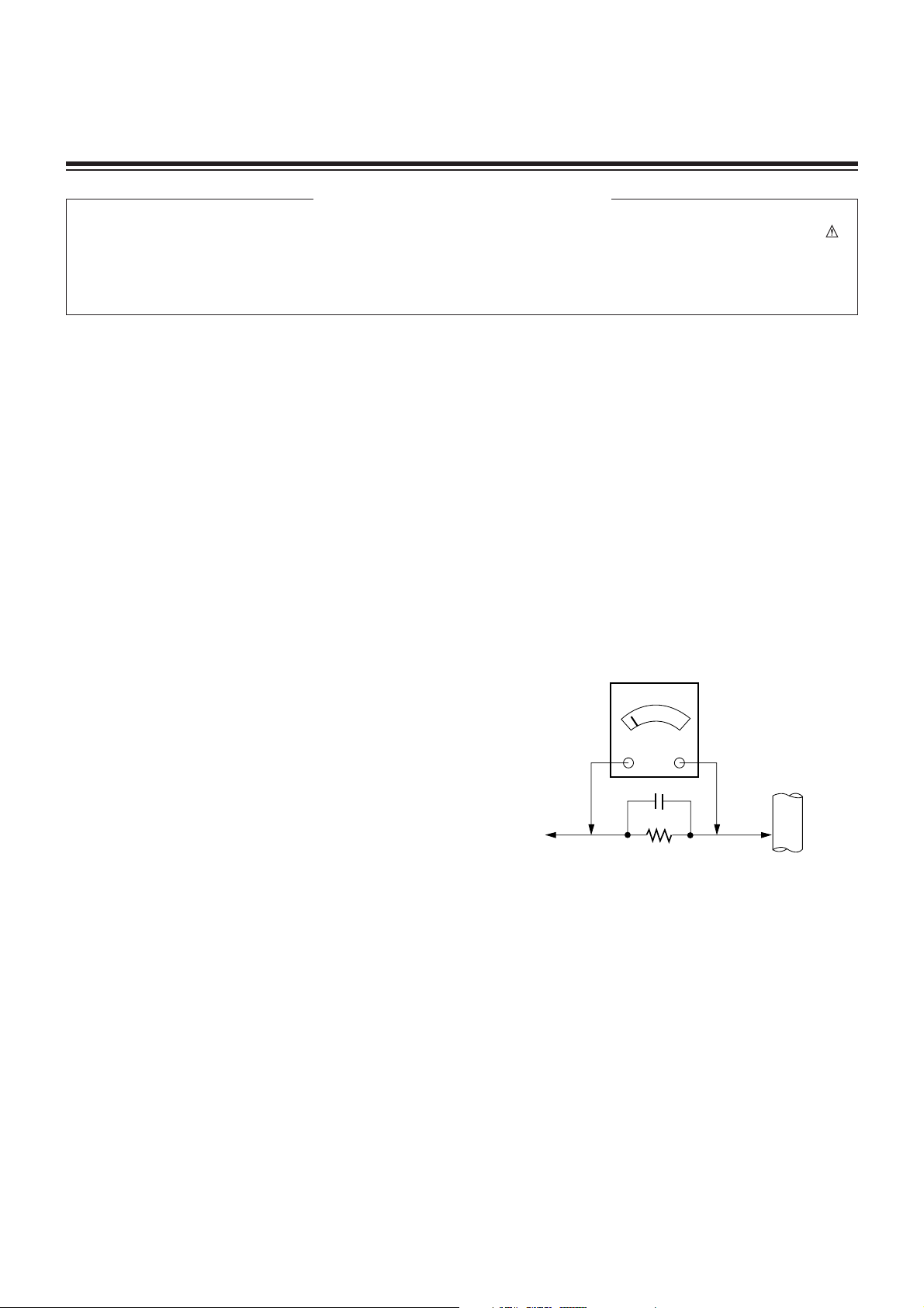
Leakage Current Hot Check (See below Figure)
Plug the AC cord directly into the AC outlet.
Do not use a line Isolation Transformer during this check.
Connect 1.5K/10watt resistor in parallel with a 0.15uF capacitor
between a known good earth ground (Water Pipe, Conduit, etc.)
and the exposed metallic parts.
Measure the AC voltage across the resistor using AC
voltmeter with 1000 ohms/volt or more sensitivity.
Reverse plug the AC cord into the AC outlet and repeat AC
voltage measurements for each esposed metallic part. Any
voltage measured must not exceed 0.75 volt RMS which is
corresponds to 0.5mA.
In case any measurement is out of the limits sepcified, there is
possibility of shock hazard and the set must be checked and
repaired before it is returned to the customer.
Leakage Current Hot Check circuit
1.5 Kohm/10W
To Instrument's
exposed
METALLIC PARTS
Good Earth Ground
such as WATER PIPE,
CONDUIT etc.
AC Volt-meter
IMPORTANT SAFETY NOTICE
0.15uF

- 3 -
DESCRIPTION OF CONTROLS...........................................4
SPECIFICATIONS.................................................................7
ADJUSTMENT INSTRUCTION.............................................8
PRINTED CIRCUIT BOARD ...............................................11
BLOCK DIAGRAM...............................................................17
EXPLODED VIEW...............................................................18
EXPLODED VIEW PARTS LIST.........................................19
REPLACEMENT PARTS LIST............................................20
SCHEMATIC DIAGRAM..........................................................
TABLE OF CONTENTS
- 4 -
Controls
Controls
TV/VIDEO
ON/OFF
S-VIDEO
A/V INPUT 2
VIDEO
AUDIO
R
L/MONO
MENU VOL
CH
TV/VIDEO MENU VOL CH
ON/OFF S-VIDEO VIDEO AUDIO
L/MONO
A/V INPUT 2
R
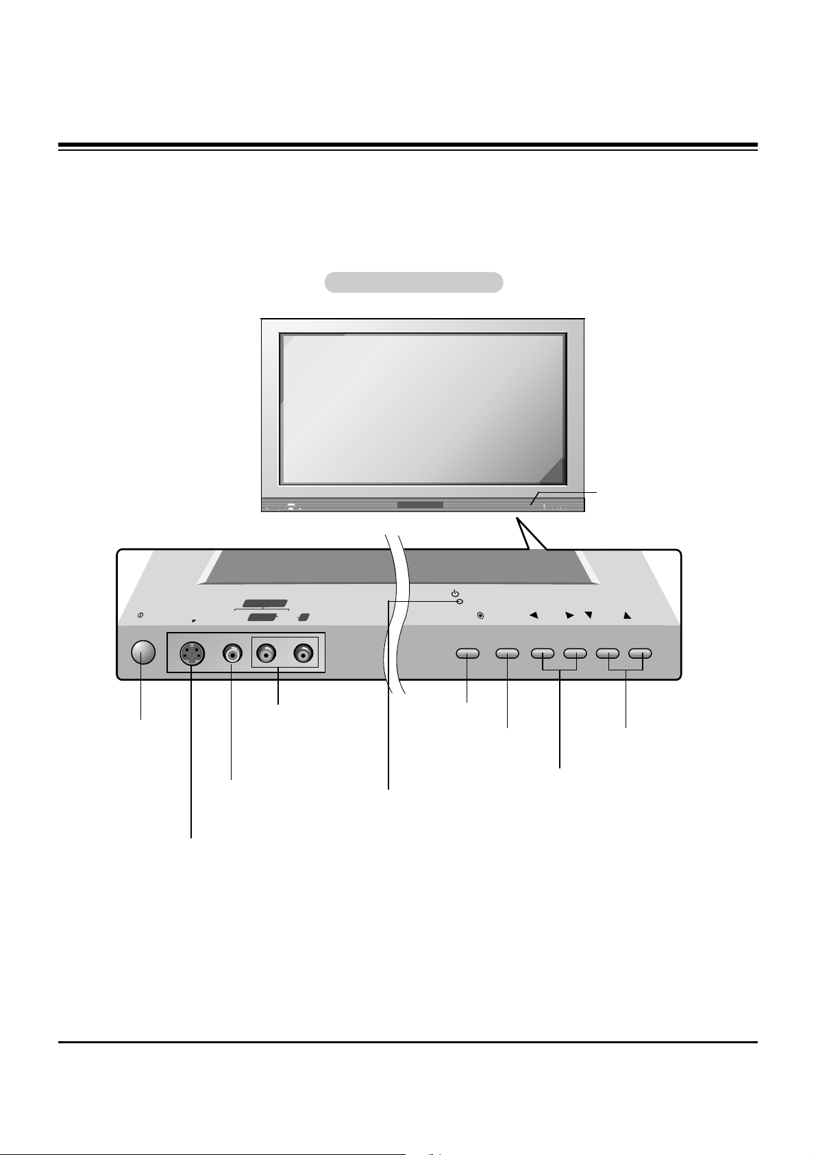
Power Button
S-VIDEO Input
A connection available to provide better
picture quality than the video input.
VIDEO Input
Connects the video signal
from a video device.
AUDIO Input
Use to connect to hear
stereo sound from an
external device.
TV/VIDEO Button
VOLUME (
FF,GG
) Buttons
Power Standby Indicator
Illuminates red in standby mode,
Illuminates green when the TV is
turned on.
- This is a simplified representation of front panel.
Here shown may be somewhat different from your TV.
Remote Control Sensor
CHANNEL (EE, DD) Buttons
MENU Button
Front Panel Controls
Front Panel Controls
DESCRIPTION OF CONTROLS

- 5 -
Connection Options
Connection Options
RGB INPUT
Antenna1 Antenna 2
AUDIO INPUT
DVI INPUT
S-VIDEO
REMOTE
CONTROL
AC INPUT
EXTERNAL SPEAKER
AUDIO INPUT
AUDIO VIDEO
VIDEO INPUT
DIGITAL AUDIO
(OPTICAL)
COMPONENT 2
MONITOR
OUTPUT
A/V
INPUT1
(MONO)
DVD
/DTV
INPUT
COMPONENT 1
DVI
INPUT
R L R L
R
L
COMPONENT1
INPUT
OUTPUT
RS-232C INPUT
(CONTROL/SERVICE)
Back Connection Panel
Back Connection Panel
Antenna 1-2 Inputs
Connect cable or antenna
signals to the TV, either
directly or through your
cable box. For DTV use
Antenna 2 only.
RGB Input/Audio Input/DVI Input
Connect the monitor output connector from
a PC to the appropriate input port.
Digital Audio (DVI: Digital Visual
Interface/Component1) Input/
Digital Audio Output
Connect digital audio from various types
of equipment. Note: In standby mode,
these ports will not work.
Audio/Video Input 1
Connect audio/video output from an
external device to these jacks.
DVD/DTV Input (Component 1-2)
Connect a component video/audio device to these jacks.
Monitor Output
Connect a second TV or
Monitor.
Remote Control Port
Connect your wired remote
control here.
S-Video Input
Connect S-Video out from an S-VIDEO
device to the S-VIDEO input.
External Speaker (8 ohm Output)
Connect to optional external speaker(s).
* For further information, refer to ‘Speaker &
Speaker Stand’ manual.
Power Cord Socket
This TV operates on an AC power. The voltage is indi-
cated on the Specifications page. Never attempt to oper-
ate the TV on DC power.
- This manual explains the features available on the DU-50PZ60/70 series TVs.
DESCRIPTION OF CONTROLS
- 6 -
DESCRIPTION OF CONTROLS
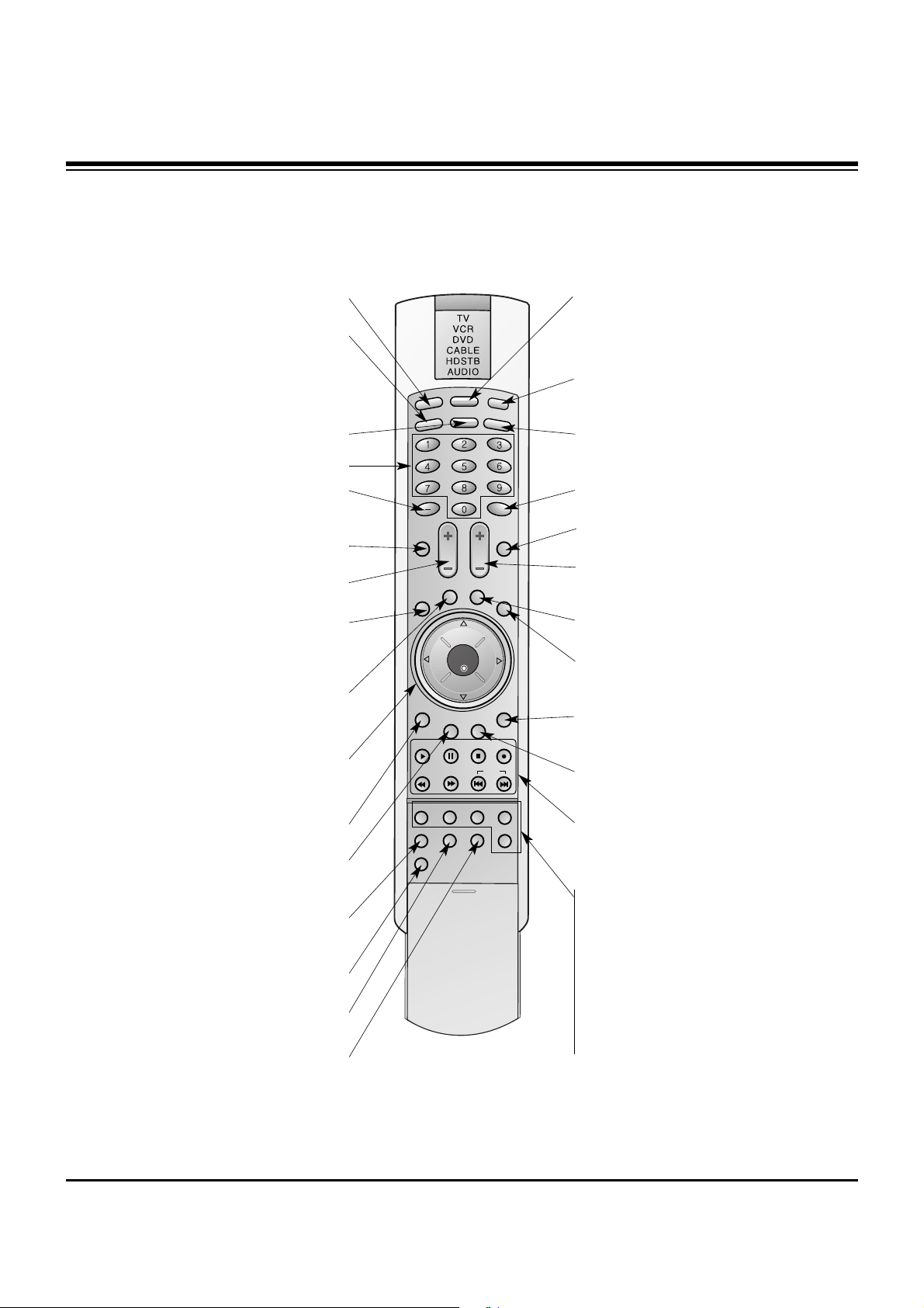
- When using the remote control, aim it at the remote control sensor on the TV.
LIGHT
TV/VIDEO
MODE
COMP/RGB/DVI
MUTE
SURF
VOL CH
INFO
SAP
RATIO
CC
MENU
SOUND VIDEO
EXIT
PLAY PAUSE STOP RECORD
PIP PIPCH- PIPCH+ PIPINPUT
FREEZE
ADJUST
OK
ZOOM SIGNAL SWAP
REW FF SKIP
POWER
TIMER
FLASHBK
LIGHT
Illuminates the remote control buttons.
TV/VIDEO
Selects: DTV, Analog, Video1-2,
Component 1-2, RGB-DTV (or RGB-PC),
DVI-DTV (or DVI-PC) input sources.
COMP/RGB/DVI
Selects: Component 1-2, RGB-DTV (or RGB-
PC), DVI-DTV (or DVI-PC) input sources.
NUMBER buttons
DASH
Used to enter a program number for multiple
program channels such as 2—1,2—2,etc.
MUTE
Switches the sound on or off.
VCR/DVD BUTTONS
Control some video cassette recorders or
DVD player ("RECORD" button is not available for DVD player).
RATIO
Changes the aspect ratio.
MODE
Selects the remote operating mode: TV,
VCR, DVD, CABLE, HDSTB or AUDIO.
Select other operating modes, for the
remote to operate external devices.
POWER
Turns your TV or any other programmed
equipment on or off, depending on mode.
TIMER
Lets you select the amount of time before
your TV turns itself off automatically.
SURF
Use to scroll the Surf channel list.
CC
Select a closed caption:
Off, EZ Mute, and On.
FLASHBK
Tunes to the last channel viewed.
THUMBSTICK (Up/Down/Left/Right/OK)
Allows you to navigate the on-screen
menus and adjust the system settings to
your preference.
CHANNEL UP/DOWN
Selects available channels found
with EZ scan.
EXIT
Clears all on-screen displays and returns to
TV viewing from any menu.
VIDEO
Adjusts the factory preset picture according
to the room.
VOLUME UP/DOWN
Increases/decreases the sound level.
SAP
Selects MTS sound: Mono, Stereo, and SAP.
Change the audio language in DTV mode.
MENU
Brings up the main menu to the screen.
INFO
When you watch the TV, displays information
on top of the screen. Not available in
Component 1-2, RGB and DVI mode.
SOUND
Selects the sound appropriate
for the program's character.
PIP
Switches between PIP, POP (Picture-out-ofPicture) and Twin picture modes.
PIPCH-/PIPCH+
Changes to next higher/lower PIP channel.
PIP INPUT
Selects the input source for the sub picture.
SWAP
Exchanges the PIP/main images.
FREEZE
Freezes the currently-viewed picture. Main
picture is frozen in PIP/Twin picturre mode.
ADJUST
Adjusts screen position, clock, and
phase in PC mode.
ZOOM
Enlarges the main picture size.
SIGNAL
Displays the digital signal strength.
Remote Control Key Functions
Remote Control Key Functions
- 7 -
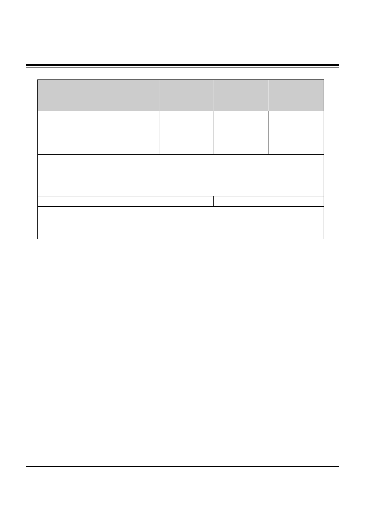
• The specifications shown above may be changed without prior notice for quality improvement.
MODELS
AC120V, 60Hz
NTSC-M, ATSC
VHF 2 ~ 13, UHF 14 ~ 69, CATV 1 ~ 125, CADTV 1 ~ 135
75 Ω
1024 x 768 (Dot) 1366 x 768 (Dot)
16,770,000 (256 steps of each R, G and B)
32 ~ 104°F (0 ~ 40°C)
Less than 80%
41 / 1040
26.3 / 668
3.7 / 95
75 / 34
41 / 1040
26.4 / 669.4
3.7 / 95
75 / 34
48.2 / 1225
30.6 / 778
3.85 / 98
101.2 / 45.9
48.3 / 1226.2
30.6 / 778
3.9 / 99
98.1 / 44.5
Width (inches / mm)
Height (inches / mm)
Depth (inches / mm)
Weight (pounds / kg)
Power requirement
Television System
Program Coverage
External Antenna Impedance
Resolution
Color
Operating Temperature Range
Operating Humidity Range
DU-42PZ60/42PZ60A
/42PZ60B/42PZ60C
/42PZ60H/42PZ60K
/42PZ60R/42PZ60S
DU-50PZ60/50PZ60A
/50PZ60B/50PZ60C
/50PZ60H/50PZ60K
/50PZ60R/50PZ60S
DU-42PZ70/42PZ70A
/42PZ70B/42PZ70C
/42PZ70H/42PZ70K
/42PZ70R/42PZ70S
DU-50PZ70/50PZ70A
/50PZ70B/50PZ70C
/50PZ70H/50PZ70K
/50PZ70R/50PZ70S
SPECIFICATIONS

1. Application Object
These instructions are applied to all of the PDP TV, AF-03BA.
2. Notes
(1) Because this is not a hot chassis, it is not necessary to use
an isolation transformer. However, the use of isolation
transformer will help protect test instrument.
(2) Adjustment must be done in the correct order.
(3) The adjustment must be performed in the circumstance of
25±5°C of temperature and 65±10% of relative humidity if
there is no specific designation.
(4) The input voltage of the receiver must keep 100~240V,
50/60Hz in adjusting.
(5) The receiver must be operated for about 15 minutes prior
to the adjustment.
1) After receiving 100% white pattern(06CH), the receiver
must be operate prior to adjustment. (Or 3. White
Pattern condition in EZ - Adjust)
2) Enter into White Pattern
- Enter the Ez - Adjust by pressing ADJ Key on R/C for
adjustment.
- Select the 3. White Pattern using CH +/- Key and
press the Enter(
Y) Key.
Display the 100% Full White Pattern.
[ Set is activated HEAT-RUN without signal generator in
this mode.
If you turn on a still screen more than 20 minutes (Especially
Digital pattern(13 CH), Cross Hatch Pattern), a afterimage may
be occur in the black level part of the screen.
3. EPLD Download
(1) Test Equipment: Jig for PC, download
(2) Connect the power of VSC B/D.
(3) Execute download program(Flash Loader) of PC.
(4) After executing execution hot key (Programmer), icon click
(5) End after confirming
Each PCB Assy must be checked by Check JIG Set before
assembly. (Especially, be careful Power PCB Assy which can
cause fatal Damage to PDP Module.)
4. POWER PCB Assy Voltage
Adjustment
(Va, Vs Voltage Adjustment)
4-1 Test Equipment :D.M.M 1EA
4-2 Connection Diagram for Measuring
Refer to Fig 2.
4-3 Adjustment Method
(1) Va Adjustment
1) Connect + terminal of D.M.M to Va pin of P805 and
connect – terminal to GND pin of P805.
2) After turning the RV601, voltage of D.M.M adjustment as
same as Va voltage which on label of panel Right/Top.
(Deviation : ±0.5V)
(2) Vs adjustment
1) Connect + terminal of D.M.M to Vs pin of P805 and connect
– terminal to GND pin of P805.
2) After turning the RV401, voltage of D.M.M adjustment as
same as Vs voltage which on label of panel Right/Top.
(Deviation : ±0.5V)
- 8 -
ADJUSTMENT INSTRUCTIONS
PC
VSC
B/D
<Fig 1> Connection Diagram of EPLD Download
<Fig 2> Connection Diagram of Power Adjustment for Measuring
- 9 -
5. AD9883A-Set Adjustment
5-1 Synopsis
AD9883A-Set adjustment to set the black level and the Gain
of optimum with an automatic movement from the analog =>
digital converter and RGB revises a deviation a function for it
is.
5-2 Test Equipment
R/C for adjustment, 801GF(802B, 802F, 802R) Pattern
Generator
(720P The Vertical 100% Color Bar Pattern output will be
possible and the output level will accurately have to be
revised with 0.7±0.1Vp-p)
5-3 Adjustment
(1) Input the 100% Vertical Color Bar Pattern(TVBAR_100) of
720P Mode possible Component input support, select the
Component1 or Component2 an input selection and select
the Clear image.
(2) After signal receiving above 1 second, press the ADJ Key
on R/C for adjustment enter the ‘Ez - Adjust’ and select the
‘5. AD9883A-Set’.
Pressing the + Key adjust with automatic movement.
(3) When the adjustment is over in the normality and the
message which is a ‘AD9883 - Set’ becomes the display
and the case which has not become the normality the
message which is a ‘AD9883A set error’ becomes the
display.
(4) Readjust after confirming the case Pattern or adjustment
condition where the adjustment had not become the
normality.
(5) After adjustment complete, exit the adjustment mode by
press ADJ KEY.
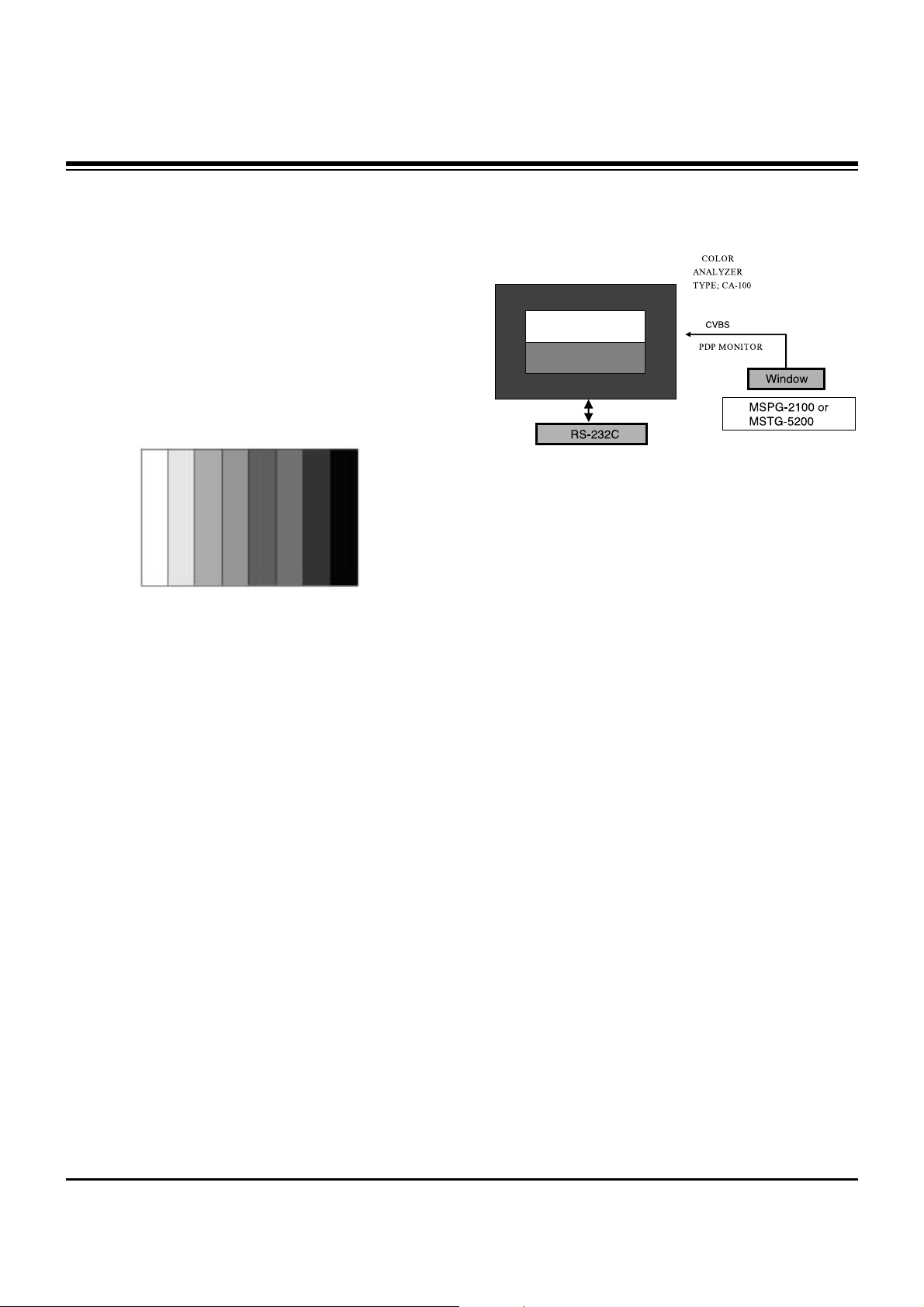
6. Adjustment of White Balance
6-1. Required Equipment
(1) Color analyzer (CA-100 or same product)
(2) Automatic adjustor (with automatic adjustment hour
necessity and the RS-232C communication being possible)
(3) AV Pattern Generator
6-2. Connection Diagram of Equipment for
Measuring (Automatic Adjustment)
6-3. Adjustment of White Balance
O
Operate the Zero-calibration of the CA-100, then stick sensor
to PDP module surface when you adjust.
O
For manual adjustment, it is also possible by the following
sequence.
(1) Enter the ‘Ez - Adjust’ by pressing ADJ KEY on R/C for
adjustment.
(2) Select the 3. WHITE PATTERN using CH +/- Key and HEAT
RUN above 15 minutes by pressing the ENTER Key.
(3) Receive the Window pattern signal from AV Pattern
Generator. (AV Input)
(4) Set Picture condition to “CLEAR Image”.
(5) After stick sensor to center of screen, select the ‘2. White-
Balance’ of ‘Ez - Adjust’ by pressing the ADJ KEY n R/C for
adjustment. And enter adjustment mode by pressing the Right
KEY(
G
) .
(6) Adjust the Hight Light using R Gain/B Gain and adjust the
Low Light using G Cut/B Cut.
(7) Adjust using Volume +/- KEY.
(G Gain : 120 / R Cut : 63)
Hight Light : 150±10 Cd
Low Light : 5±2 Cd
X; 0.280±0.003
Y; 0.290±0.003
Color temperature: 10,000°K±500°K
(8) After adjustment complete, move to Ez - Adjust screen by
pressing the ENTER(Y) KEY. And exit the adjustment mode
by press ADJ KEY.
ADJUSTMENT INSTRUCTIONS
<Fig 3> Adjustment Pattern : 720P Vertical Color Bar
High Light Adjustment
Low Light Adjustment
Signal Input
<Fig 4> Connection Diagram of Automatic Adjustment

- 10 -
6-4. Main/Sub Contrast Adjustment
Main/Sub contrast adjustment is adjustment reduces the
contrast difference of Main/Sub screen in PIP/POP/SPLIT
Screen.
(1) After signal receiving above 1 second, press the ADJ KEY
on R/C for adjustment enter the ‘Ez - Adjust’ and select the
‘2. VPX3226’.
Enter adjustment mode by pressing the Right KEY(
G
).
(2) When enter adjustment mode, becomes the image TV
6CH SPLIT Screen with automatic movement and appear
below window.
(3) The contour of “US 6CH” letter of left Main screen is most
clear and it is clear, 1.Contrast (Main) after adjusting first,
in order for right side Sub screen to contrast to become the
left Main screen to contrast with same, 2.Contrast (Sub) it
adjust. This time adjust using the volume +/- Key.
(4) After adjustment complete, exit the adjustment mode by
press ADJ KEY.
ADJUSTMENT INSTRUCTIONS
 Loading...