

LG DU-50PX10x Service Manual

PLASMA TV
OWNER’S MANUAL
Please read this manual carefully and completely before
operating your TV.
Retain this manual for future reference.
Record model number and serial number of the TV in the
spaces provided below.
See the label attached on the back cover and relate this
information to your dealer if you require service.
Model Number :
Serial Number :
MODEL: DU-50PX10/10C
DU-42PX12X/12XC
LG Electronics U.S.A., Inc.
2 Plasma TV
Warning
WARNING:
TO REDUCE THE RISK OF ELECTRIC SHOCK DO NOT REMOVE COVER (OR BACK). NO USER
SERVICEABLE PARTS INSIDE. REFER TO QUALIFIED SERVICE PERSONNEL.
The lightning flash with arrowhead symbol, within an equilateral triangle, is intended to alert the user to
the presence of uninsulated “dangerous voltage” within the product’s enclosure that may be of sufficient
magnitude to constitute a risk of electric shock to persons.
The exclamation point within an equilateral triangle is intended to alert the user to the presence of impor-
tant operating and maintenance (servicing) instructions in the literature accompanying the appliance.
WARNING:
TO PREVENT FIRE OR SHOCK HAZARDS, DO NOT EXPOSE THIS PRODUCT TO RAIN OR MOISTURE.
POWER CORD POLARIZATION:
CAUTION: TO PREVENT ELECTRIC SHOCK, MATCH WIDE BLADE OF PLUG TO WIDE SLOT, FULLY INSERT.
NOTE TO CABLE/TV INSTALLER:
This reminder is provided to call the CATV system installer’s attention to Article 820-40 of the National Electric Code
(U.S.A.). The code provides guidelines for proper grounding and, in particular, specifies that the cable ground shall be
connected to the grounding system of the building, as close to the point of the cable entry as practical.
REGULATORY INFORMATION:
This equipment has been tested and found to comply with the limits for a Class B digital device, pursuant to Part 15 of
the FCC Rules. These limits are designed to provide reasonable protection against harmful interference when the equipment is operated in a residential installation. This equipment generates, uses and can radiate radio frequency energy
and, if not installed and used in accordance with the instruction manual, may cause harmful interference to radio communications. However, there is no guarantee that interference will not occur in a particular installation. If this equipment
does cause harmful interference to radio or television reception, which can be determined by turning the equipment off
and on, the user is encouraged to try to correct the interference by one or more of the following measures:
• Reorient or relocate the receiving antenna.
• Increase the separation between the equipment and receiver.
• Connect the equipment into an outlet on a circuit different from that to which the receiver is connected.
• Consult the dealer or an experienced radio/TV technician for help.
Any changes or modifications not expressly approved by the party responsible for compliance could void the user’s
authority to operate the equipment.
CAUTION:
Do not attempt to modify this product in any way without written authorization from LG Electronics. Unauthorized modification could void the user’s authority to operate this product.
COMPLIANCE:
The responsible party for this product’s compliance is:
LG Electronics U.S.A., Inc
1000 Sylvan Avenue, Englewood Cliffs, NJ 07632
1-201-816-2000
http://www.lgusa.com
WARNING
RISK OF ELECTRIC SHOCK
DO NOT OPEN
W
W
arning
arning

Owner’s Manual 3
Safety Instructions
Important safeguards for you and your new product
Your product has been manufactured and tested with your safety in mind. However, improper use can result in electrical
shock or fire hazards. To avoid defeating the safeguards that have been built into your new product, please read and observe
the following safety points when installing and using your new product, and save them for future reference.
Observing the simple precautions discussed in this manual can help you get many years of enjoyment and safe operation
that are built into your new product.
This product complies with all applicable U.S. Federal safety requirements, and those of the Canadian Standards Association.
1. Read Instructions
All the safety and operating instructions should be read
before the product is operated.
2. Follow Instructions
All operating and use instructions should be followed.
3. Retain Instructions
The safety and operating instructions should be retained for
future reference.
4. Heed Warnings
All warnings on the product and in the operating instructions
should be adhered to.
5. Cleaning
Unplug this product from the wall outlet before cleaning. Do
not use liquid cleaners or aerosol cleaners. Use a damp
cloth for cleaning.
6. Water and Moisture
Do not use this product near water, for example, near a bath
tub, wash bowl, kitchen sink, or laundry tub, in a wet basement, or near a swimming pool.
7. Accessories, Carts, and Stands
Do not place this product on a slippery or tilted surface, or on
an unstable cart, stand, tripod, bracket, or table. The product
may slide or fall, causing serious injury to a child or adult,
and serious damage to the product. Use only with a cart,
stand, tripod, bracket, or table recommended by the manufacturer, or sold with the product. Any mounting of the product should follow the manufacturer’s instructions, and should
use a mounting accessory recommended by the manufacturer.
8. Transporting Product
A product and cart combination should be moved with care.
Quick stops, excessive force, and uneven surfaces may
cause the product and cart combination to overturn.
9. Attachments
Do not use attachments not recommended by the product
manufacturer as they may cause hazards.
10. Ventilation
Slots and openings in the cabinet are provided for ventilation
and to ensure reliable operation of the product and to protect
it from overheating, and these openings must not be blocked
or covered. The openings should never be blocked by placing the product on a bed, sofa, rug, or other similar surface.
This product should not be placed in a built-in installation
such as a bookcase or rack unless proper ventilation is provided or the manufacturer’s instructions have been adhered
to.
11. Power Sources
This product should be operated only from the type of power
source indicated on the marking label. If you are not sure of
the type of power supply to your home, consult your product
dealer or local power company. For products intended to
operate from battery power, or other sources, refer to the
operating instructions.
12. Power-Cord Polarization
This product is equipped with a three-wire grounding type
plug, a plug having a third (grounding) pin. This plug will only
fit into the grounding-type power outlet. This is a safety feature. If you are unable to insert the plug into the outlet, contact your electrician to replace your obsolete outlet. Do not
defeat the safety purpose of the grounding-type plug.
13. Power-Cord Protection
Power-supply cords should be routed so that they are not
likely to be walked on or pinched by items placed upon or
against them, paying particular attention to cords at plugs,
convenience receptacles, and the point where they exit from
the product.
PORTABLE CART WARNING
Safety Instructions
Safety Instructions
4 Plasma TV
Safety Instructions
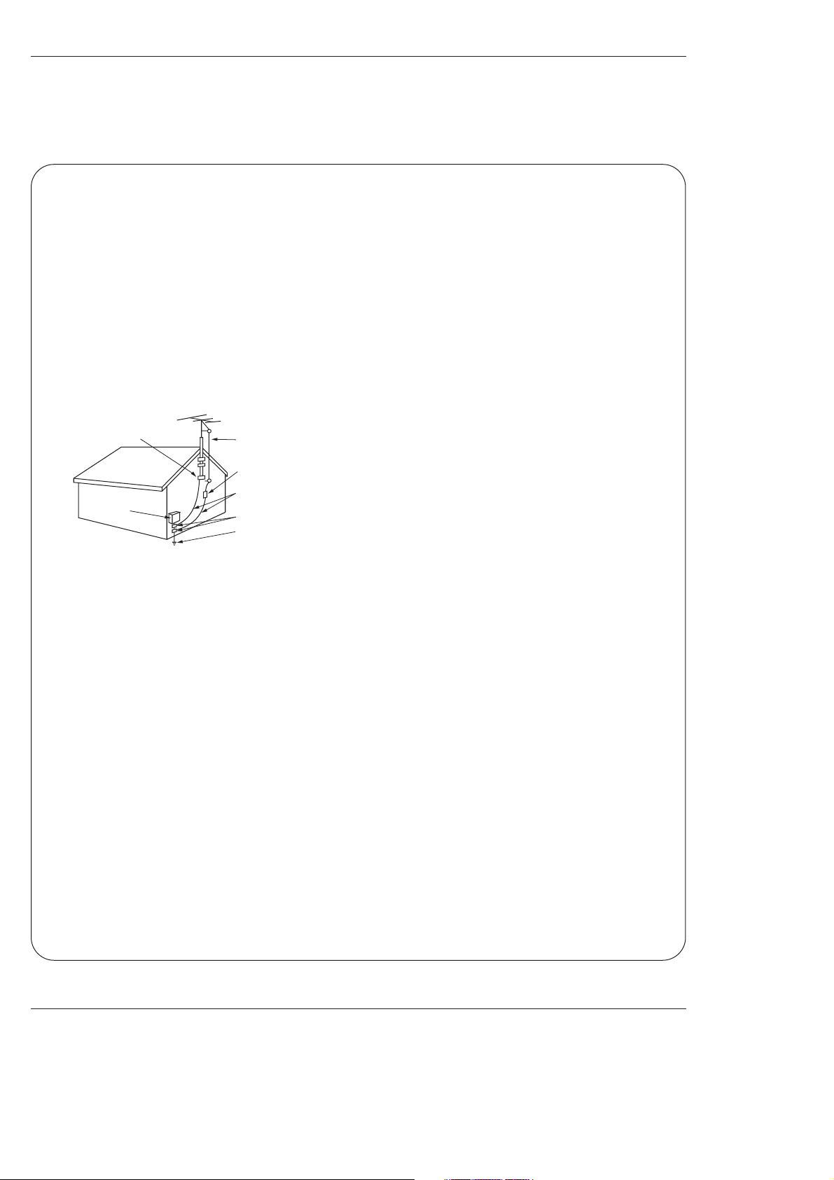
Antenna Lead in Wire
Antenna Discharge Unit
(NEC Section 810-20)
Grounding Conductor
(NEC Section 810-21)
Ground Clamps
Power Service Grounding
Electrode System (NEC
Art 250, Part H)
Ground Clamp
Electric Service
Equipment
Example of Grounding According to National
Electrical Code Instructions
NEC - National Electrical Code
14. Outdoor Antenna Grounding
If an outside antenna or cable system is connected to the
product, be sure the antenna or cable system is grounded so
as to provide some protection against voltage surges and
built-up static charges. Article 810 of the National Electrical
Code (U.S.A.), ANSI/ NFPA 70 provides information with
regard to proper grounding of the mast and supporting structure, grounding of the lead-in wire to an antenna discharge
unit, size of grounding conductors, location of antenna-discharge unit, connection to grounding electrodes, and
requirements for the grounding electrode.
15. Lightning
For added protection for this product (receiver) during a lightning storm, or when it is left unattended and unused for long
periods of time, unplug it from the wall outlet and disconnect
the antenna or cable system. This will prevent damage to the
product due to lightning and power-line surges.
16. Power Lines
An outside antenna system should not be located in the
vicinity of overhead power lines or other electric light or
power circuits, or where it can fall into such power lines or
circuits. When installing an outside antenna system, extreme
care should be taken to keep from touching such power lines
or circuits as contact with them might be fatal.
17. Overloading
Do not overload wall outlets and extension cords as this can
result in a risk of fire or electric shock.
18. Object and Liquid Entry
Never push objects of any kind into this product through
openings as they may touch dangerous voltage points or
short-out parts that could result in a fire or electric shock.
Never spill liquid of any kind on the product.
19. Servicing
Do not attempt to service this product yourself as opening or
removing covers may expose you to dangerous voltage or
other hazards. Refer all servicing to qualified service personnel.
20. Damage Requiring Service
Unplug this product from the wall outlet and refer servicing to
qualified service personnel under the following conditions:
a. If the power-supply cord or plug is damaged.
b. If liquid has been spilled, or objects have fallen into the
product.
c. If the product has been exposed to rain or water.
d. If the product does not operate normally by following the
operating instructions. Adjust only those controls that are
covered by the operating instructions as an improper
adjustment of other controls may result in damage and
will often require extensive work by a qualified technician
to restore the product to its normal operation.
e. If the product has been dropped or the cabinet has been
damaged.
f. If the product exhibits a distinct change in performance.
21. Replacement Parts
When replacement parts are required, be sure the service
technician has used replacement parts specified by the manufacturer or have the same characteristics as the original
part. Unauthorized substitutions may result in fire, electric
shock, or other hazards.
22. Safety Check
Upon completion of any service or repairs to this product,
ask the service technician to perform safety checks to determine that the product is in proper operating condition.
23. Wall or Ceiling Mounting
The product should be mounted to a wall or ceiling only as
recommended by the manufacturer. The product may slide
or fall, causing serious injury to a child or adult, and serious
damage to the product.
24. Heat
The product should be situated away from heat sources
such as radiators, heat registers, stoves, or other products
(including amplifiers) that produce heat.
Safety Instructions continued
Safety Instructions continued

Owner’s Manual 5
Contents
After reading this manual, keep it handy for future reference.
Warnings . . . . . . . . . . . . . . . . . . . . . . . . . . . . . . . . . . . . .2
Safety Instructions . . . . . . . . . . . . . . . . . . . . . . . . . . . . .3~4
Introduction
Controls . . . . . . . . . . . . . . . . . . . . . . . . . . . . . . .7
Connection Options . . . . . . . . . . . . . . . . . . . . . .8
Remote Control Key Functions . . . . . . . . . . . . . .9
Installation
Installation Instruction . . . . . . . . . . . . . . . . . . .10~11
External Equipment Connections . . . . . . . . . .12~16
Antenna Connection . . . . . . . . . . . . . . . . . . . . .12
VCR Setup / Cable TV Setup . . . . . . . . . . . . . .13
External A/V Source Setup . . . . . . . . . . . . . . . .14
Monitor Out Setup / DVD Setup . . . . . . . . . . . .14
HDSTB Setup / Digital Audio Output . . . . . . . . .15
PC Setup . . . . . . . . . . . . . . . . . . . . . . . . . . . . .16
Operation
Screen Setup for PC mode . . . . . . . . . . . . . . . . . .17
Turning the TV On . . . . . . . . . . . . . . . . . . . . . . . .18
On-screen Menus Language Selection . . . . . . . . .18
Setup Menu Options
EZ Scan (Channel Search) . . . . . . . . . . . . . . . .19
Channel Edit . . . . . . . . . . . . . . . . . . . . . . . . . . .19
DTV Signal Strength . . . . . . . . . . . . . . . . . . . . .20
Channel Label Setup . . . . . . . . . . . . . . . . . . . .20
Main Picture Source Selection . . . . . . . . . . . . .20
Video Menu Options
EZ Picture . . . . . . . . . . . . . . . . . . . . . . . . . . . .21
Manual Picture Control (Off Option) . . . . . . . . .21
Color Temperature Control . . . . . . . . . . . . . . . .21
Video Preset . . . . . . . . . . . . . . . . . . . . . . . . . .21
Audio Menu Options
Audio Language . . . . . . . . . . . . . . . . . . . . . . . .22
EZ SoundRite / EZ Sound . . . . . . . . . . . . . . . . .22
Manual Sound Control (Off Option) . . . . . . . . . .23
Stereo/SAP Broadcasts Setup . . . . . . . . . . . . .23
Front Surround . . . . . . . . . . . . . . . . . . . . . . . . .23
TV Speakers On/Off Setup . . . . . . . . . . . . . . . .24
BBE . . . . . . . . . . . . . . . . . . . . . . . . . . . . . . . . .24
Time Menu Options
Auto Clock Setup . . . . . . . . . . . . . . . . . . . . . . .25
Manual Clock Setup . . . . . . . . . . . . . . . . . . . . .25
On/Off Timer Setup . . . . . . . . . . . . . . . . . . . . .25
Sleep Timer / Auto Off . . . . . . . . . . . . . . . . . . . .26
Option Menu Features
Aspect Ratio . . . . . . . . . . . . . . . . . . . . . . . . . . .27
Caption / Caption Mode . . . . . . . . . . . . . . . . . .28
Caption Option . . . . . . . . . . . . . . . . . . . . . . . .29
Cinema Mode Setup . . . . . . . . . . . . . . . . . . . .29
Demo . . . . . . . . . . . . . . . . . . . . . . . . . . . . . . .29
ISM Method . . . . . . . . . . . . . . . . . . . . . . . . . . .30
Low power . . . . . . . . . . . . . . . . . . . . . . . . . . . .30
Split Zoom . . . . . . . . . . . . . . . . . . . . . . . . . . . .30
Lock Menu Options
Parental Lock Setup . . . . . . . . . . . . . . . . . . . . .32
PIP (Picture-in-Picture)/POP/Twin Picture
Watching PIP/POP/Twin Picture . . . . . . . . . . . ..33
Selecting an Input Signal Source for PIP/Twin Picture
. .33
Swapping the PIP/Twin Picture . . . . . . . . . . . . .33
TV Program Selection for PIP . . . . . . . . . . . . . .33
Moving the PIP sub picture . . . . . . . . . . . . . . . .34
Adjusting Main and Sub Picture Sizes for Twin Picture . .34
POP (Picture-out-of-Picture: Channel Scan) . . .34
External Control Device Setup . . . . . . . . . . . . . . . .35~39
IR Codes . . . . . . . . . . . . . . . . . . . . . . . . . . . . . . . .40~41
Programming the Remote . . . . . . . . . . . . . . . . . . . . . .42
Programming Codes . . . . . . . . . . . . . . . . . . . . . . .43~44
Troubleshooting Checklist . . . . . . . . . . . . . . . . . . . . . .45
Maintenance . . . . . . . . . . . . . . . . . . . . . . . . . . . . . . . . .46
Product Specifications . . . . . . . . . . . . . . . . . . . . . . . . .46
Warranty . . . . . . . . . . . . . . . . . . . . . . . . . . . . . . . . .47~48
Contents
Contents
Setup and Operation Checklist
Setup and Operation Checklist
Setup and Operation Checklist
(See pages 11~16 for available connection and operational setup options.)
1. Unpack TV and all accessories.
2. Connect all external video and audio equipment.
see pages 14 ~ 16.
3 Install batteries in remote control.
See page 9.
4. Turn TV on.
See page 18.
5. Turn video source equipment on.
6. Select viewing source for TV.
See page 20.
7. Fine-tune source image and sound to your personal preference or as required by source.
See pages 21 ~ 24.
8. Additional features set up
See Contents above.

6 Plasma TV
Introduction
Introduction
Introduction
What is a Plasma Display Panel (PDP)?
A plasma display panel is the latest display technology and the best way to achieve flat panel displays with excellent image quality
and large screen sizes that are easily viewable. The PDP can be thought of as a descendant of the neon lamp and it can be also
be viewed as a series of fluorescent lamps.
How does it work?
PDP is an array of cells, known as pixels, which are comprised of 3 sub pixels, corresponding to the colors red, green, and blue.
Gas in a plasma state is used to react with phosphors in each sub-pixel to produce colored light (red, green, or blue). These phosphors are the same types used in Cathode Ray Tube (CRT) devices such as televisions and common computer monitors.
You get the rich, dynamic colors that you expect. Each sub-pixel is individually controlled by advanced electronics to produce over
16 million different colors. All of this means that you get perfect images that are easily viewable in a display that is less than 5
inches thick.
160° - Wide angle range of vision
Your flat panel plasma screen offers an exceptionally broad viewing angle -- over 160 degrees. This means that the display is
clear and visible to viewers anywhere in the room who can see the screen.
Wide Screen
The screen of the Plasma Display is so wide that your viewing experience is as if you are in a theater.
Multimedia
Connect your plasma display to a PC and you can use it for conferencing, games, and Internet browsing. The Picture-in-Picture
feature allows you to view your PC and video images simultaneously.
Versatile
The light weight and thin size makes it easy to install your plasma display in a variety of locations where conventional TVs will not
fit.
The PDP Manufacturing Process: a few minute colored dots may be present on the PDP screen
The PDP (Plasma Display Panel), which is the display device of this product is composed of 0.9 to 2.2 million cells. A few cell
defects will normally occur in the PDP manufacturing process. Several tiny, minute colored dots visible on the screen should be
acceptable. This also occurs in other PDP manufacturers' products. The tiny dots appearing does not mean that this PDP is defective. Thus a few cell defects are not sufficient cause for the PDP to be exchanged or returned. Our production technology minimizes these cell defects during the manufacture and operation of this product.
Cooling Fan Noise (DU-50PX10 only)
In the same way that a fan is used in a PC computer to keep the CPU (Central Processing Unit) cool, the PDP is equipped with
cooling fans to cool the Monitor and improve its reliability. Therefore, a certain level of noise could occur while the fans are operating and cooling the PDP.
The fan noise doesn't have any negative effect on the PDP's efficiency or reliability. The noise from these fans is normal during the
operation of this product. We hope you understand that a certain level of noise from the cooling fans is acceptable and is not sufficient cause for the PDP to be exchanged or returned.
Owner’s Manual 7
Introduction
Controls
Controls
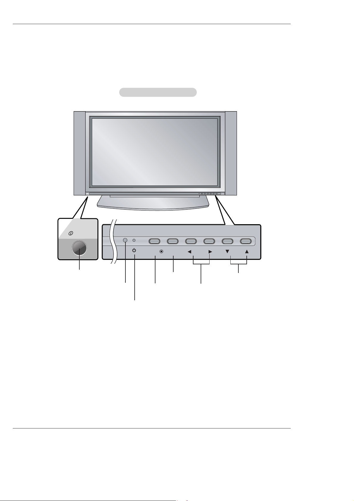
ON/OFF
TV/VIDEO
MENU
VOL CH
- This is a simplified representation of front panel.
Image shown may be somewhat different from your TV.
- This manual explains the features available on the DU-50PX10 series TVs.
Front Panel Controls
Front Panel Controls
ON/OFF Button
Remote Control Sensor
VOLUME (
F,G) Buttons
Power Standby Indicator
Illuminates red in standby mode,
Illuminates green when the TV is
turned on.
CHANNEL (E, D) Buttons
MENU Button
TV/VIDEO Button
8 Plasma TV
Introduction
Connection Options
Connection Options
R
S-VIDEO VIDEO
L / MONO
AUDIO
A/V 2
REMOTE
CONTROL
RS-232C INPUT
(CONTROL/SERVICE)
AC INPUT
AUDIO INPUT
COMPONENT 2
COMPONENT 1
RL
DIGITAL AUDIO
(OPTICAL)
DVI
INPUT
COMPONENT1
INPUT
OUTPUT
AUDIO INPUT
DVI INPUT
(PC/DTV INPUT)
RGB INPUT
(PC/DTV INPUT)
VIDEO INPUT
DVD
DTV
INPUT
MONITOR
OUTPUT
A/V
INPUT 1
AUDIO
R L
(MONO)
VIDEO
S-VIDEO
Antenna 1
Analog/DTV
Antenna 2
DTV
.
Back Connection Panel
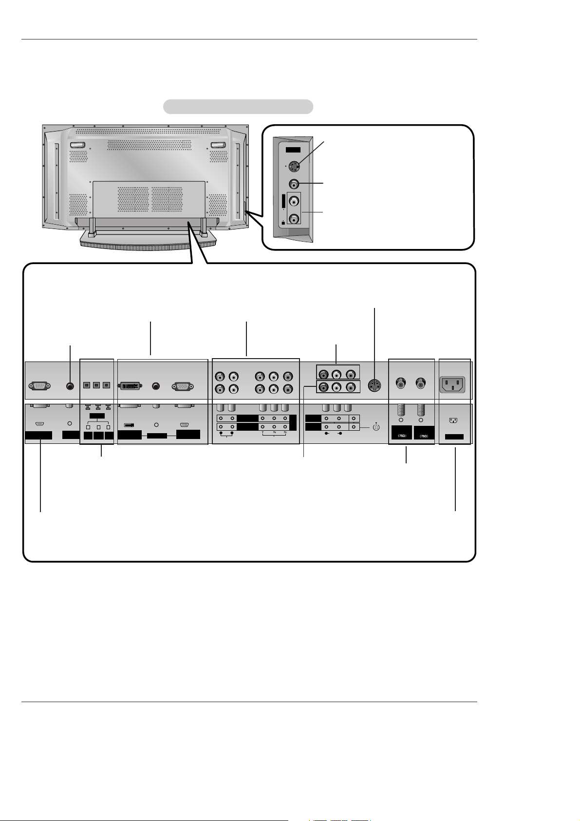
Back Connection Panel
Antenna 1-2 Inputs
Connect cable or antenna signals to the
TV, either directly or through your cable
box. For DTV use Antenna 2 only.
DVI Input/Audio Input/RGB
Input
Connect the monitor output connector from a PC to the appropriate input port.
Digital Audio (DVI: Digital Visual
Interface/Component1) Input/
Digital Audio Output
Connect digital audio from various types
of equipment. Note: In standby mode,
these ports will not work.
Audio/Video Input 1
Connect audio/video out-
put from an external
device to these jacks.
DVD/DTV Input (Component
1-2)
Connect a component
video/audio device to these
jacks.
Monitor Output
Connect a second TV or
Monitor.
Remote Control
Port
Connect your wired
remote control here.
S-Video Input
Connect S-Video out from an
S-VIDEO device to the SVIDEO input.
Power Cord Socket
This TV operates on an AC power. The voltage is indi-
cated on the Specifications page. Never attempt to oper-
ate the TV on DC power.
- This manual explains the features available on the DU-50PX10 series TVs.
S-VIDEO Input
A connection available to provide better
picture quality than the video input.
VIDEO Input
Connects the video signal from a video
device.
AUDIO Input
Use to connect to hear stereo sound
from an external device.
RS-232C INPUT
(CONTROL/SERVICE) PORT
Connect to the RS-232C port
on a PC.
Owner’s Manual 9
Installation
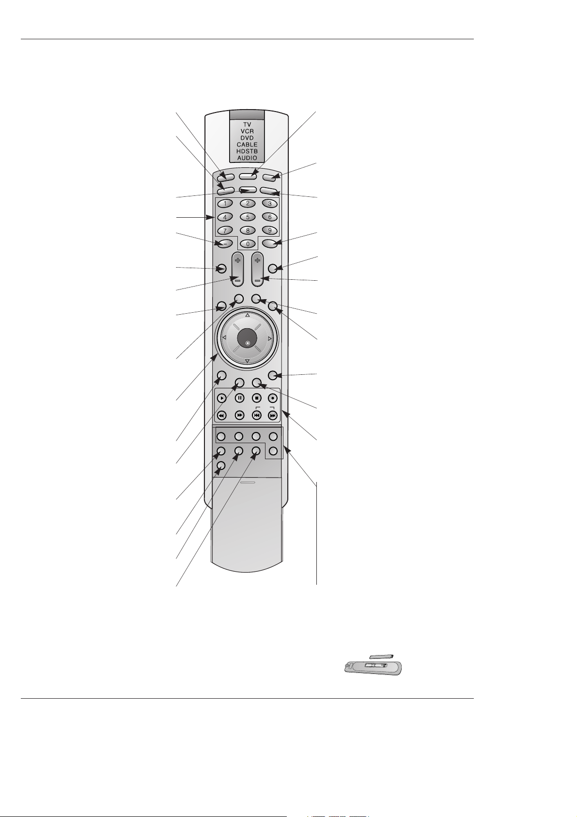
- When using the remote control, aim it at the remote control sensor on the TV.
LIGHT
TV/VIDEO
MODE
COMP/RGB/DVI
MUTE
SURF
VOL CH
INFO
SAP
RATIO
CC
MENU
SOUND VIDEO
EXIT
PLAY PAUSE STOP RECORD
PIP PIPCH- PIPCH+ PIPINPUT
FREEZE
ADJUST
OK
ZOOM SIGNAL SWAP
REW FF SKIP
POWER
TIM
ER
FLASHBK
LIGHT
Illuminates the remote control buttons.
TV/VIDEO
Selects: DTV, Analog, Video1-2,
Component 1-2, RGB-DTV (or RGB-PC),
DVI-DTV (or DVI-PC) input sources.
COMP/RGB/DVI
Selects: Component 1-2, RGB-DTV (or RGB-
PC), DVI-DTV (or DVI-PC) input sources.
NUMBER buttons
DASH
Used to enter a program number for multiple
program channels such as 2-1,2-2,etc.
MUTE
Switches the sound on or off.
VCR/DVD BUTTONS
Control some video cassette recorders or
DVD player ("RECORD" button is not available for DVD player).
RATIO
Changes the aspect ratio.
MODE
Selects the remote operating mode: TV,
VCR, DVD, CABLE, HDSTB or AUDIO.
Select other operating modes, for the
remote to operate external devices.
POWER
Turns your TV or any other programmed
equipment on or off, depending on mode.
TIMER
Lets you select the amount of time before
your TV turns itself off automatically.
SURF
Use to scroll the Surf channel list.
CC
Select a closed caption:
Off, EZ Mute, and On.
FLASHBK
Tunes to the last channel viewed.
THUMBSTICK (Up/Down/Left/Right/OK)
Allows you to navigate the on-screen
menus and adjust the system settings to
your preference.
CHANNEL UP/DOWN
Selects available channels found
with EZ scan.
EXIT
Clears all on-screen displays and returns to
TV viewing from any menu.
VIDEO
Adjusts the factory preset picture according
to the room.
VOLUME UP/DOWN
Increases/decreases the sound level.
SAP
Selects MTS sound: Mono, Stereo, and SAP.
Change the audio language in DTV mode.
MENU
Brings up the main menu to the screen.
INFO
When you watch the TV, displays information
on top of the screen. Not available in
Component 1-2, RGB and DVI mode.
SOUND
Selects the sound appropriate
for the program's character.
PIP
Switches between PIP, POP (Picture-out-ofPicture) and Twin picture modes.
PIPCH-/PIPCH+
Changes to next higher/lower PIP channel.
PIP INPUT
Selects the input source for the sub picture.
SWAP
Exchanges the PIP/main images.
FREEZE
Freezes the currently-viewed picture. Main
picture is frozen in PIP/Twin picturre mode.
ADJUST
Adjusts screen position, clock, and
phase in PC mode.
ZOOM
Enlarges the main picture size.
SIGNAL
Displays the digital signal strength.
Installing Batteries
• Open the battery compartment cover on the back side and install the batteries
matching correct polarity (+ with +, - with -).
• Install two 1.5V AA batteries. Don’t mix old or used batteries with new ones.
Replace cover.
Remote Control Key Functions
Remote Control Key Functions
10 Plasma TV
Installation
Installation
Installation
Owner’s Manual
1.5V
1.5V
Batteries
Power Cord
L
I
G
H
T
T
V
/
V
I
D
E
O
MODE
COMP/RGB/DVI
MUTE
SURF
VOL CH
INFO
SAP
RATIO
CC
MENU
SOUNDVIDEO
EXIT
PLAY PAUSE STOPRECORD
PIP PIPCH- PIPCH+ PIPINPUT
FREEZE
ADJUST
OK
ZOOM SIGNAL SWAP
REW FF SKIP
P
O
W
E
R
T
IM
E
R
FLASHBK
Remote Control
75Ω Round Cable
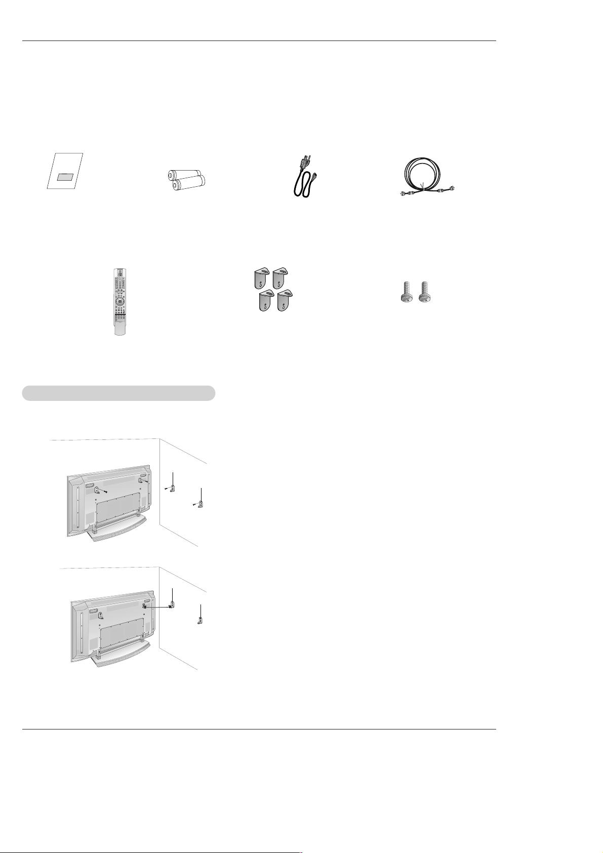
Ensure that the following accessories are included with your plasma display. If an accessory is missing, please contact the dealer
where you purchased the product.
- Secure the TV assembly by attaching it to a wall for additional support.
Attaching the
Attaching the
TV assembly to the wall
TV assembly to the wall
• Install the TV brackets on the TV as shown.
Insert the 2 bolts and tighten securely, in the holes on the bracket. (42”)
After removing the existing bolts, Insert the 4 bolts and tighten securely,
in the holes on the bracket.(50”)
Install the wall brackets on the wall with 4 bolts*,
(not supplied with the product), as shown.
Match the height of the TV brackets and the wall brackets.
Check to be sure the brackets are tightened securely.
• Secure the TV assembly to the wall with strong strings or
wound wire cables, (not supplied with the product), as
shown.
2-TV brackets
2-Wall brackets
2-TV bracket bolts(42”)
4-TV bracket bolts(50”)
Owner’s Manual 11
Installation
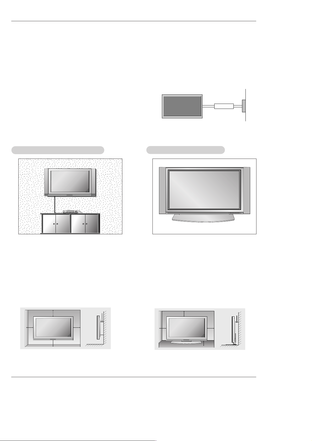
Installation Instructions
Installation Instructions
• The TV can be installed in various ways such as on a wall, or on a desktop etc.
• The TV is designed to be mounted horizontally. The speakers shown are optional.
GROUNDING
Ensure that you connect the grounding / earth wire to prevent possible
electric shock. If grounding methods are not possible, have a qualified
electrician install a separate circuit breaker. Do not try to ground the
unit by connecting it to telephone wires, lightening rods, or gas pipes.
Power
Supply
Short-circuit
Breaker
WWall Mount: Horizontal installation
all Mount: Horizontal installation
For proper ventilation, allow a clearance of 4” on each
side and 2” from the wall. Detailed installation instructions are available from your dealer, see the optional
Wall Mounting Bracket Installation and Setup Guide.
Desktop Pedestal Installation
Desktop Pedestal Installation
For proper ventilation, allow a clearance of 4” on each
side and the top, 2.36” on the bottom, and 2” from the
wall. Detailed installation instructions are included in
the optional Desktop Stand Installation and Setup
Guide available from your dealer.
To Mount on a Wall
Wall mount minimum allowable clearances for adequate ventilation.
To Install on a Desktop
Pedestal mount minimum allowable clearances for
adequate ventilation.
4 inches
4 inches4 inches
4 inches
2 inches
4 inches
4 inches
4 inches
2.36 inches
2 inches
12 Plasma TV
Installation
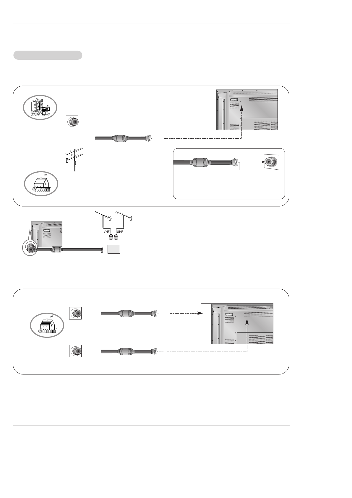
- Antenna or Cable Service without a Cable Box Connections
- For optimum picture quality, adjust antenna direction if needed.
Antenna Connection
Antenna Connection
Analog and Digital TV signals provided on one antenna
NOTE: If you are not sure of the type of signal(s) you are receiving, let EZ Scan complete all the channel signal-type searches.
The TV will let you know when the analog, cable, and digital channel scans are complete.
Analog and DTV signals provided on two separate antennas
• In a poor signal area to improve picture quality, purchase
and install a signal amplifier.
• If the antenna needs to be split for two TV’s, install a “2Way Signal Splitter” in the connections.
• If the antenna is not installed properly, contact your dealer for assistance.
Multi-family Dwellings/Apartments
(Connect to wall antenna socket)
Single-family Dwellings /Houses
(Connect to wall jack for outdoor antenna)
Outdoor
Antenna
Wall Antenna
Socket
VHF Antenna
UHF Antenna
RF Coaxial Wire (75 ohm)
Copper Wire
Turn clockwise to tighten.
Copper Wire
Be careful not to bend the Copper wire when
connecting the antenna.
Wall Antenna
Socket
RF Coaxial Wire (75 ohm)
Analog Antenna
Digital Antenna
Copper Wire
Copper Wire
Turn clockwise to tighten.
Wall Antenna
Socket
RF Coaxial Wire (75 ohm)
Plasma TV
External Equipment Connections
External Equipment Connections
Signal
Amplifier
Owner’s Manual 13
Installation
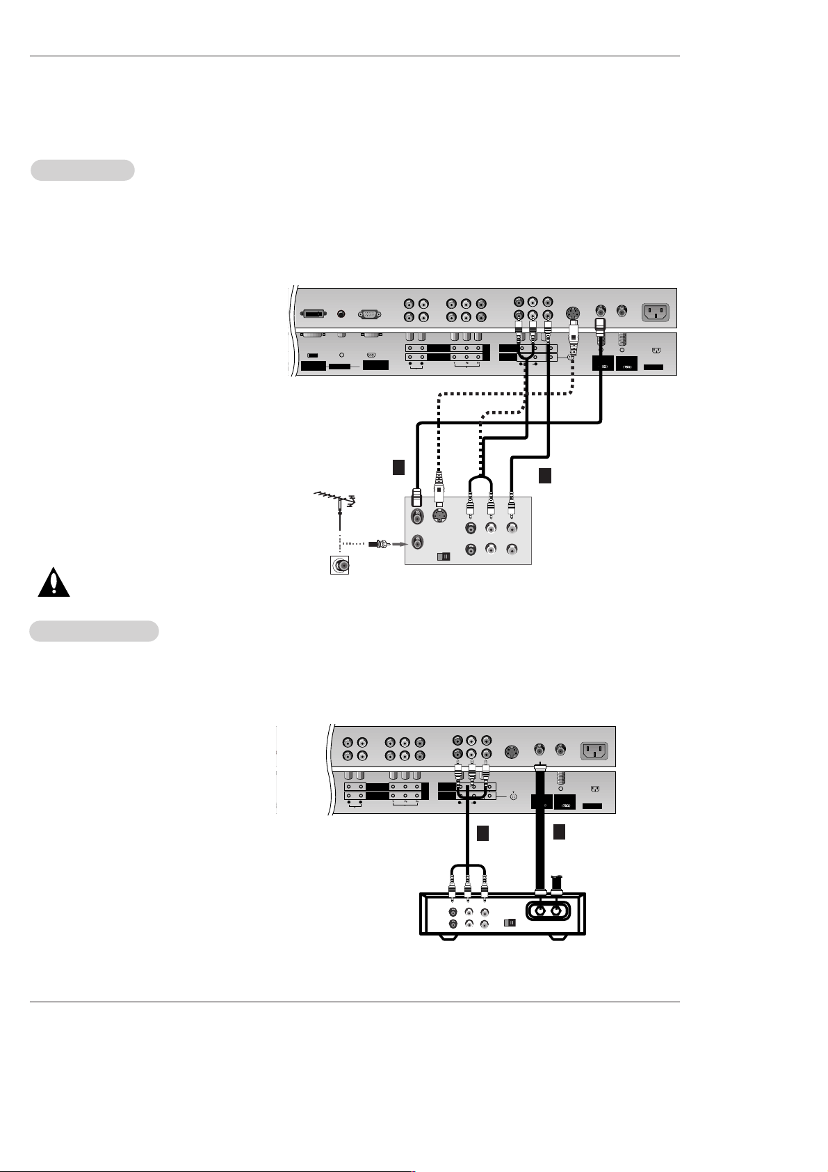
NOTE: All cables shown are not included with the TV
- To avoid picture noise (interference), leave an adequate distance between the VCR and TV
- Use the ISM Method (on the Option menu) feature to avoid having a fixed image remain on the screen for a long period of time.
Typically a frozen still picture from a VCR. If the 4:3 picture format is used; the fixed images on the sides of the screen may
remain visible on the screen.
Connection Option 1
Set VCR output switch to 3 or 4 and then tune
TV to the same channel number.
Connection Option 2
1. Connect the audio and video cables from the
VCR's output jacks to the TV input jacks, as
shown in the figure.
When connecting the TV to VCR, match the
jack colors (Video = yellow, Audio Left = white,
and Audio Right = red).
If you connect an S-VIDEO output from VCR to
the S-VIDEO input, the picture quality is
improved; compared to connecting a regular
VCR to the Video input.
2. Insert a video tape into the VCR and press
PLAY on the VCR. (Refer to the VCR owner’s
manual.)
3. Select the input source with using the
TV/VIDEO button on the remote control. (If
connected to A/V INPUT 1, select Video 1
input source)
Do not connect to both Video and
S-Video at the same time.
VCR Setup
VCR Setup
AC INPUT
AUDIO INPUT
COMPONENT 2
COMPONENT 1
RL
TPUT
AUDIO INPUT
DVI INPUT
(PC/DTV INPUT)
RGB INPUT
(PC/DTV INPUT)
VIDEO INPUT
DVD
DTV
INPUT
MONITOR
OUTPUT
A/V
INPUT 1
AUDIO
R L
(MONO)
VIDEO
S-VIDEO
Antenna 1
Analog/DTV
Antenna 2
DTV
S-VIDEO
OUT
IN
(R) AUDIO (L) VIDEO
34
OUTPUT
SWITCH
ANT OUT
ANT IN
.
- After subscribing to a cable TV service from a local provider and installing a converter, you can watch cable TV programming.
The TV cannot display TV programming unless a TV tuner device or cable TV converter box is connected to the TV.
- For further information regarding cable TV service, contact your local cable TV service provider(s).
Connection Option 1
1. Select 3 or 4 with channel switch on cable
box.
2. Tune the TV channel to the same selected
output channel on cable box.
3. Select channels at the cable box or with the
cable box remote control.
Connection Option 2
1. Connect the audio and video cables from the
Cable Box's output jacks to the TV input jacks,
as shown in the figure.
When connecting the TV to a Cable Box,
match the jack colors (Video = yellow, Audio
Left = white, and Audio Right = red).
2. Select the input source with using the
TV/VIDEO button on the remote control. (If
connected to A/V INPUT 1, select Video 1
input source)
3. Select your desired channel with the remote
control for cable box.
Cable
Cable
TV Setup
TV Setup
AC INPUT
AUDIO INPUT
COMPONENT 2
COMPONENT 1
RL
O INPUT
RGB INPUT
(PC/DTV INPUT)
VIDEO INPUT
DVD
DTV
INPUT
MONITOR
OUTPUT
A/V
INPUT 1
AUDIO
R L
(MONO)
VIDEO
S-VIDEO
Antenna 1
Analog/DTV
Antenna 2
DTV
TV
VCR
RF Cable
(R) AUDIO (L) VIDEO
34
OUTPUT
SWITCH
.
VCR
Cable Box
1
2
1
2
14 Plasma TV
Installation
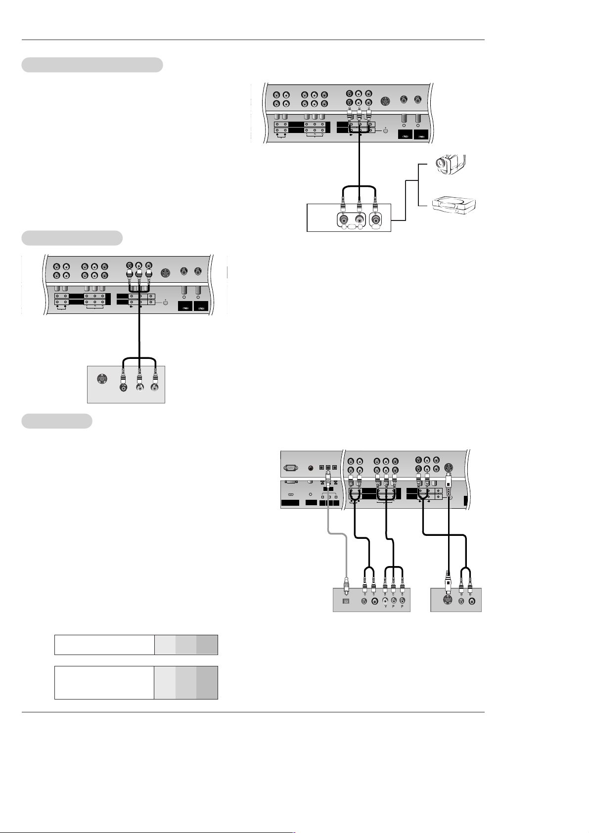
• Component Input ports
To get better picture quality, connect a DVD player to the component input ports as shown below.
How to connect
Connect the audio and video cables from the external equipment's output jacks to the TV input jacks, as shown in the
figure.
When connecting the TV to external equipment, match the
jack colors (Video = yellow, Audio Left = white, and Audio
Right = red).
How to use
1. Select the input source with using the TV/VIDEO button on
the remote control. (If connected to A/V INPUT 1, select
Video 1 input source).
2. Operate the corresponding external equipment. Refer to
external equipment operating guide.
Component ports
on the TV
Y
P
B
PR
Video output ports
on DVD player
Y
Y
Y
Y
Pb
B-Y
Cb
P
B
Pr
R-Y
Cr
PR
How to connect
1. Connect the DVD video outputs (Y, PB, PR) to the COMPONENT (Y,
PB, PR) INPUT jacks on the TV and connect the DVD audio outputs
to the AUDIO INPUT jacks on the TV, as shown in the figure.
2. If your DVD only has an S-Video output jack, connect this to the SVIDEO input on the TV and connect the DVD audio outputs to the
AUDIO INPUT jacks on the TV, as shown in the figure.
NOTE: If your DVD player does not have component video output, use
S-Video.
How to use
1. Turn on the DVD player, insert a DVD.
2. Use the TV/VIDEO or COMP/RGB/DVI button on the remote control
to select Component 1 or Component 2. (If connected to SVIDEO, select the Video 1 or Video 2 external input source.)
3. Refer to the DVD player's manual for operating instructions.
External
External
A/V Source Setup
A/V Source Setup
DVD Setup
DVD Setup
RL
AUDIO VIDEO
AC INPUT
AUDIO INPUT
COMPONENT 2
COMPONENT 1
RL
DTV INPUT)
VIDEO INPUT
DVD
DTV
INPUT
MONITOR
OUTPUT
A/V
INPUT 1
AUDIO
R L
(MONO)
VIDEO
Antenna 1
Analog/DTV
Antenna 2
DTV
S-VIDEO
.
REMOTE
CONTROL
RS-232C INPUT
(CONTROL/SERVICE)
AUDIO INPUT
COMPONENT 2
COMPONENT 1
RL
DIGITAL AUDIO
(OPTICAL)
DVI
INPUT
COMPONENT1
INPUT
OUTPUT
VIDEO INPUT
MONITOR
OUTPUT
A/V
INPUT 1
AUDIO
R L
(MONO)
VIDEO
Antenna 1
Analog/DTV
Ante
D
B
R
(R) AUDIO (L)
DIGITAL AUDIO
OPTICAL
(R) AUDIO (L)
S-VIDEO
S-VIDEO
DVD
DTV
INPUT
.
DVD
or
Camcorder
Video Game Set
The TV has a special signal output capability which allows you to
hook up a second TV or monitor.
Connect the second TV or monitor to the TV’s MONITOR OUTPUT.
See the Operating Manual of the second TV or monitor for further
details regarding that device’s input settings.
NOTE
• Component, RGB-PC/RGB-DTV, DVI-PC/DVI-DTV, DTV input
sources cannot be used for Monitor out.
NOTES
• Digital Audio will not work for Component 2 input source.
• Digital Audio operation has priority if Digital Audio and AUDIO L/R
are connected at the same time.
AC INPUT
AUDIO INPUT
COMPONENT 2
COMPONENT 1
RL
RGB INPUT
(PC/DTV INPUT)
VIDEO INPUT
MONITOR
OUTPUT
A/V
INPUT 1
AUDIO
R L
(MONO)
VIDEO
S-VIDEO
Antenna 1
Analog/DTV
Antenna 2
DTV
S-VIDEO
IN
(R) AUDIO (L)
VIDEO
DVD
DTV
INPUT
.
Monitor Out Setup
Monitor Out Setup
or
Owner’s Manual 15
Installation
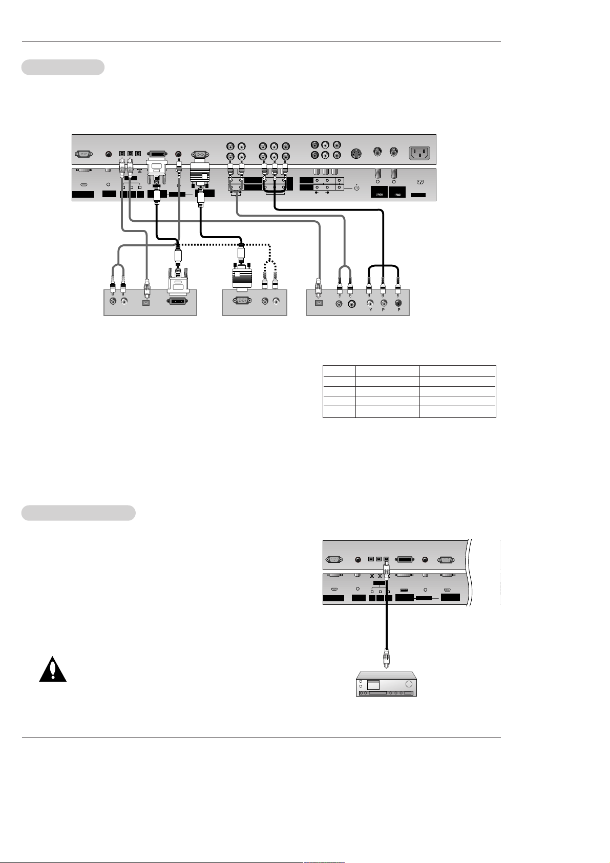
Send the TV’s audio to external audio equipment (stereo system) via
the Digital Audio Output Optical port.
How to connect
1. Connect one end of an optical cable to the TV Digital Audio Optical
Output port.
2. Connect the other end of the optical cable to the digital audio optical
input on the audio equipment.
3. Set the “ TV Speaker option - Off” in the AUDIO menu. Refer to
page 23.
See the external audio equipment instruction manual for operation.
Caution: Do not look into the optical output port.
Looking at the laser beam may damage
your vision.
Digital
Digital
Audio Output
Audio Output
- This TV can receive Digital Over-the-air/Cable signals without an external digital set-top box. However, if you do receive Digital
signals from a digital set-top box or other digital external device, refer to the figure as shown below.
- This TV supports HDCP (High-bandwidth Digital Contents Protection) protocol for DTV (480p,720p,1080i) mode.
How to connect
Use the TV’s COMPONENT (Y, PB, PR) INPUT, RGB or DVI jack for
video connections, depending on your set-top box connector. Then,
make the corresponding audio connections.
How to use
1. Turn on the digital set-top box. (Refer to the owner’s manual for the
digital set-top box.)
2. Use TV/VIDEO or COMP/RGB/DVI on the remote control to select
Component 1, Component 2, RGB-DTV, or DVI-DTV source.
HDSTB Setup
HDSTB Setup
REMOTE
CONTROL
RS-232C INPUT
(CONTROL/SERVICE)
AC INPUT
AUDIO INPUT
COMPONENT 2
COMPONENT 1
RL
DIGITAL AUDIO
(OPTICAL)
DVI
INPUT
COMPONENT1
INPUT
OUTPUT
AUDIO INPUT
DVI INPUT
(PC/DTV INPUT)
RGB INPUT
(PC/DTV INPUT)
VIDEO INPUT
MONITOR
OUTPUT
A/V
INPUT 1
AUDIO
R L
(MONO)
VIDEO
Antenna 1
Analog/DTV
Antenna 2
DTV
R
(R) AUDIO (L)
RGB-DTV OUTPUT
B
R
(R) AUDIO (L)
DIGITAL AUDIO
OPTICAL
(R) AUDIO (L)
DVI-DTV OUTPUT
DIGITAL AUDIO
OPTICAL
S-VIDEO
DVD
DTV
INPUT
.
Digital Set-top Box
or
or
or
or
REMOTE
CONTROL
RS-232C INPUT
(CONTROL/SERVICE)
AUDIO INPUT
COMPONEN
COMPONEN
RL
DIGITAL AUDIO
(OPTICAL)
DVI
INPUT
COMPONENT1
INPUT
OUTPUT
AUDIO INPUT
DVI INPUT
(PC/DTV INPUT)
RGB INPUT
(PC/DTV INPUT)
Signal
480i
480p
720p
1080i
Component 1/2
Yes
Yes
Yes
Yes
RGB-DTV,DVI-DTV
No
Yes
Yes
Yes
 Loading...