

LG Electronics DU-42LZ30, DU-37LZ30 User Manual

LCD
Colour Television
OWNER’S MANUAL
Please read this manual carefully before operating your set.
Retain it for future reference.
Record model number and serial number of the set.
See the label attached on the back cover and quote this information to your dealer when you require service.
MODELS: DU-30LZ30
DU-37LZ30
DU-42LZ30
Internet Home Page : http://www.lge.com
http://www.lg.ca
P/NO : 3828TUL275D(0406-REV00)
Printed in Korea
2
Warning
WARNING:
TO REDUCE THE RISK OF ELECTRIC SHOCK DO NOT REMOVE COVER (OR BACK). NO USER
SERVICEABLE PARTS INSIDE. REFER TO QUALIFIED SERVICE PERSONNEL.
The lightning flash with arrowhead symbol, within an equilateral triangle, is intended to alert the user to
the presence of uninsulated “dangerous voltage” within the product’s enclosure that may be of sufficient magnitude to constitute a risk of electric shock to persons.
The exclamation point within an equilateral triangle is intended to alert the user to the presence of
important operating and maintenance (servicing) instructions in the literature accompanying the appliance.
NOTE TO CABLE/TV INSTALLER:
This reminder is provided to call the CATV system installer’s attention to Article 820-40 of the National Electric
Code (U.S.A.). The code provides guidelines for proper grounding and, in particular, specifies that the cable
ground shall be connected to the grounding system of the building, as close to the point of the cable entry as practical.
REGULATORY INFORMATION
This equipment has been tested and found to comply with the limits for a Class B digital device, pursuant to Part
15 of the FCC Rules. These limits are designed to provide reasonable protection against harmful interference in
a residential installation. This equipment generates, uses and can radiate radio frequency energy and, if not
installed and used in accordance with the instructions, may cause harmful interference to radio communications.
However, there is no guarantee that interference will not occur in a particular installation. If this equipment does
cause harmful interference to radio or television reception, which can be determined by turning the equipment off
and on, the user is encouraged to try to correct the interference by one or more of the following measures:
- Reorient or relocate the receiving antenna.
- Increase the separation between the equipment and receiver.
- Connect the equipment into an outlet on a circuit different from that to which the receiver is connected.
- Consult the dealer or an experienced radio/TV technician for help.
Any changes or modifications not expressly approved by the party responsible for compliance could void the
user’s authority to operate the equipment.
CAUTION:
Do not attempt to modify this product in any way without written authorization from LG Electronics Corporation.
Unauthorized modification could void the user’s authority to operate this product.
U.S.A. only -----------------------------------------------
COMPLIANCE:
The responsible party for this product’s compliance is:
LG Electronics U.S.A., Inc.
1000 Sylvan Avenue, Englewood Cliffs, NJ 07632
Phone: 1-201-816-2000
http://www.lgusa.com
---------------------------------------------------------------
CAUTION
RISK OF ELECTRIC SHOCK
DO NOT OPEN
W
W
arning
arning

3
Safety Instructions
WARNING :
To Reduce The Risk Of Fire Or Electric Shock, Do Not Expose This Apparatus To Rain Or Moisture.
Apparatus shall not be exposed to dripping or splashing and no objects filled with liquids, such as vases, shall be placed on the
apparatus.
CAUTION :
These servicing instructions are for use by qualified service personnel only. To reduce the risk of electric shock, do not perform
any servicing other than that contained in the operating instructions unless you are qualified to do so.
IMPORTANT SAFETY INSTRUCTIONS
1. Read these instructions.
2. Keep these instructions.
3. Heed all warnings.
4. Follow all instructions.
5. Do not use this apparatus near water.
6. Clean only with a dry cloth.
7. Do not block any of the ventilation openings. Install in accordance with the manufacturer’s instructions.
8. Do not install near any heat sources such as radiators, heat registers, stoves, or other apparatus (including amplifiers) that
produce heat.
9. Do not defeat the safety purpose of the polarized or grounding type plug. Apolarized plug has two blades with one wider
than the other. A grounding type plug has two blades and a third grounding prong. The wide blade or the third prong is provided for your safety. When the provided plug does not fit into your outlet, consult an electrician for replacement of the obsolete outlet.
10. protect the power cord from being walked on or pinched particularly at plugs, convenience receptacles, and the point
where they exit from the apparatus.
11. Only use the attachments / accessories specified by the manufacturer.
Safety Instructions
Safety Instructions
4
Safety Instructions
Safety Instructions continued
Safety Instructions continued
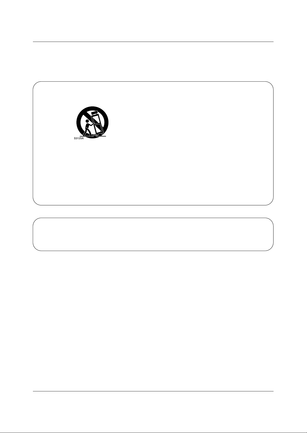
12. Use only with a cart, stand, tripod, bracket, or table specified by the manufacturer, or sold with the apparatus. When a
cart is used, use caution when moving the cart / apparatus combination to avoid injury from tip-over.
13. Unplug this apparatus during lightning storms or when unused for long periods of time.
14. Refer all servicing to qualified service personnel. Servicing is required when the apparatus has been damaged in any
way, such as power supply cord or plug is damaged, liquid has been spilled or objects have fallen into the apparatus, the
apparatus has been exposed to rain or moisture, does not operate normally, or has been dropped.
On Disposal
a. The fluorescent lamp used in this product contains a small amount of mercury.
b. Do not dispose of this product with general household waste.
Disposal of this product must be carried out in accordance to the regulations of your local authority.

5
Contents
After reading this manual, keep it handy for future reference.
Warnings . . . . . . . . . . . . . . . . . . . . . . . . . . . . . . . . . . . . .2
Safety Instructions . . . . . . . . . . . . . . . . . . . . . . . . . . . . .3~4
Introduction
Controls . . . . . . . . . . . . . . . . . . . . . . . . . . . . . . .6
Connection Options . . . . . . . . . . . . . . . . . . . . . .7
Remote Control Key Functions . . . . . . . . . . . . . .8
Installation
Installation Instruction . . . . . . . . . . . . . . . . . . . . . . .9
External Equipment Connections . . . . . . . . . .11~15
Antenna Connection . . . . . . . . . . . . . . . . . . . . .11
VCR Setup / Cable TV Setup . . . . . . . . . . . . . .12
External A/V Source Setup . . . . . . . . . . . . . . . .13
Monitor Out Setup / DVD Setup . . . . . . . . . . . .13
HDSTB Setup / Digital Audio Output . . . . . . . . .14
PC Setup . . . . . . . . . . . . . . . . . . . . . . . . . . . . .15
Operation
Screen Setup for PC mode
Adjustments for screen position, clock, and phase
. .16
Turning the TV On . . . . . . . . . . . . . . . . . . . . . . . .17
On-screen Menus Language Selection . . . . . . . . .17
Setup Menu Options
EZ Scan (Channel Search) . . . . . . . . . . . . . . . .18
Channel Edit . . . . . . . . . . . . . . . . . . . . . . . . . . .18
DTV Signal Strength . . . . . . . . . . . . . . . . . . . . .19
Channel Label Setup . . . . . . . . . . . . . . . . . . . .19
Main Picture Source Selection . . . . . . . . . . . . .20
Front LED (Light Emitting Diode) Display . . . . .20
Video Menu Options
EZ Picture . . . . . . . . . . . . . . . . . . . . . . . . . . . .21
Manual Picture Control (User Option) . . . . . . . .21
XD Function . . . . . . . . . . . . . . . . . . . . . . . . . . .21
Color Temperature Control . . . . . . . . . . . . . . . .22
Video Preset . . . . . . . . . . . . . . . . . . . . . . . . . .22
Audio Menu Options
Audio Language . . . . . . . . . . . . . . . . . . . . . . . .23
EZ SoundRite / EZ Sound . . . . . . . . . . . . . . . . .23
Manual Sound Control (User Option) . . . . . . . .23
Stereo/SAP Broadcasts Setup . . . . . . . . . . . . .24
Front Surround . . . . . . . . . . . . . . . . . . . . . . . . .24
TV Speakers On/Off Setup . . . . . . . . . . . . . . . .24
Time Menu Options
Auto Clock Setup . . . . . . . . . . . . . . . . . . . . . . .25
Manual Clock Setup . . . . . . . . . . . . . . . . . . . . .25
On/Off Timer Setup . . . . . . . . . . . . . . . . . . . . .25
Sleep Timer / Auto Off . . . . . . . . . . . . . . . . . . . .26
Option Menu Features
Aspect Ratio . . . . . . . . . . . . . . . . . . . . . . . . . . .27
Caption / Caption Mode . . . . . . . . . . . . . . . . . .28
Caption Option / Cinema Mode Setup . . . . . . . .29
Demo (Review) . . . . . . . . . . . . . . . . . . . . . . . . .29
Split Zoom . . . . . . . . . . . . . . . . . . . . . . . . . . . .29
Lock Menu Options
Parental Lock Setup . . . . . . . . . . . . . . . . . . . . .31
PIP (Picture-in-Picture)/Twin Picture
Watching PIP/POP/Twin Picture . . . . . . . . . . . ..32
Selecting an Input Signal Source for PIP/Twin Picture
. .32
Swapping PIP/POP/Twin Picture . . . . . . . . . . . .32
TV Program Selection for PIP . . . . . . . . . . . . . .32
Moving the PIP sub picture . . . . . . . . . . . . . . . .33
Adjusting Main and Sub Picture Sizes for Twin Picture . .33
POP (Picture-out-of-Picture: Channel Scan) . . .33
External Control Device Setup . . . . . . . . . . . . . . . .34~38
IR Codes . . . . . . . . . . . . . . . . . . . . . . . . . . . . . . . .39~40
Programming the Remote . . . . . . . . . . . . . . . . . . . . . .41
Programming Codes . . . . . . . . . . . . . . . . . . . . . . .42~43
Troubleshooting Checklist . . . . . . . . . . . . . . . . . . . . . .44
Maintenance . . . . . . . . . . . . . . . . . . . . . . . . . . . . . . . . .45
Product Specifications . . . . . . . . . . . . . . . . . . . . . . . . .46
Troubleshooting Checklist . . . . . . . . . . . . . . . . . . . . . .47
Contents
Contents
Setup and Operation Checklist
Setup and Operation Checklist
Setup and Operation Checklist
(See pages 11~15 for available connection and operational setup options.)
1. Unpack TV and all accessories.
2. Connect all external video and audio equipment.
see pages 11 ~ 15.
3 Install batteries in remote control.
See page 8.
4. Turn TV on.
See page 17.
5. Turn video source equipment on.
6. Select viewing source for TV.
See page 20.
7. Fine-tune source image and sound to your personal preference or as required by source.
See pages 21 ~ 24.
8. Additional features set up
See Contents above.
6
Introduction
Introduction
Introduction
CH
VOL
ENTER
MENU
VIDEO
ON/OFF
TV
/I
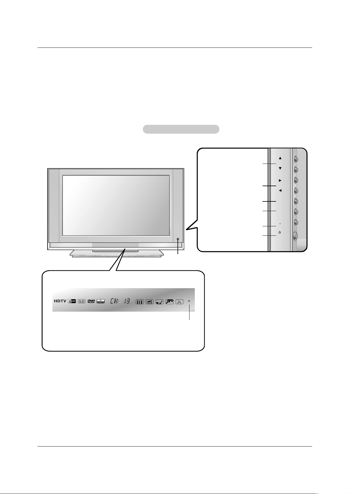
TV/VIDEO Button
VOLUME (
FF,GG
) Buttons
Power Standby Indicator
Illuminates brightly when the TV
is in standby mode. Dims when
the TV is switched on.
- This is a simplified representation of front panel.
Here shown may be somewhat different from your TV.
- This manual explains the features available on the DU-42LZ30 TV.
Remote Control Sensor
CHANNEL (EE, DD) Buttons
MENU Button
ENTER Button
ON/OFF Button
Front Panel Controls
Front Panel Controls
7
Introduction
Connection Options
Connection Options
Antenna1
Antenna 2
S-VIDEO
REMOTE
CONTROL
UPGRADE
PORT
RGB INPUT
(PC/DTV INPUT)
DVI INPUT
(PC/DTV INPUT)
AC INPUT
AUDIO INPUT
AUDIO VIDEO
VIDEO INPUT
DIGITAL AUDIO
(OPTICAL)
COMPONENT 2
MONITOR
OUTPUT
A/V
INPUT1
(MONO)
DVD
/DTV
INPUT
COMPONENT 1
DVI
INPUT
PC/DVI
AUDIO INPUT
RL
R L
COMPONENT1
INPUT
OUTPUT
S-VIDEO
IN2
VIDEOL/MONOAUDIOR
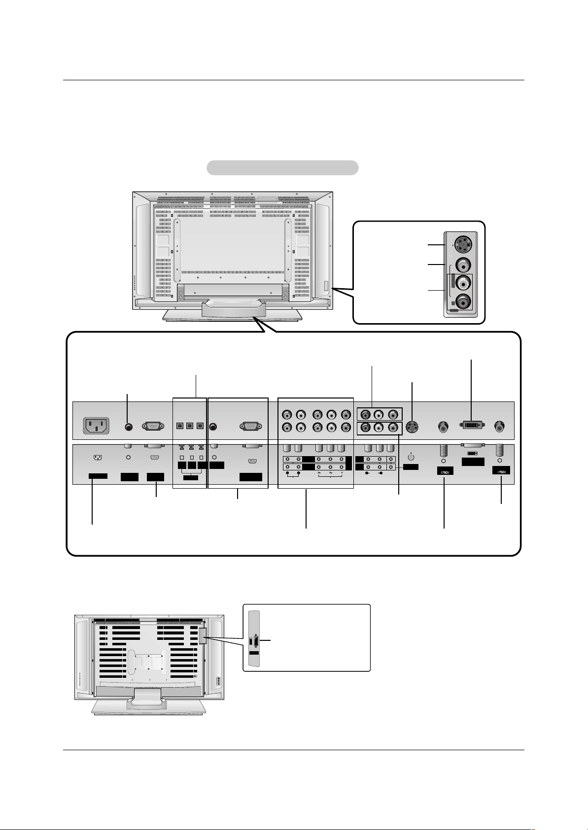
Back Connection Panel
Back Connection Panel
Antenna1 Input
RGB Input (PC/DTV Input)
PC/DTV Audio Input
Digital Audio Inputs (DVI, Component1)/
Digital Audio Output
Audio/Video Input 1
DVD/DTV Input (Component 1,2)
Monitor Output
Remote Control Port
S-Video Input
DVI Input (PC/DTV Input)
Antenna2 Input
Power Cord Socket
Upgrade Port
- This manual explains the features available on the DU-42LZ30 TVs.
S-VIDEO Input
VIDEO Input
AUDIO Input
DVI Input (PC/DTV Input)
* DU-30LZ30
DVI INPUT
(PC/DTV INPUT)
8
Introduction
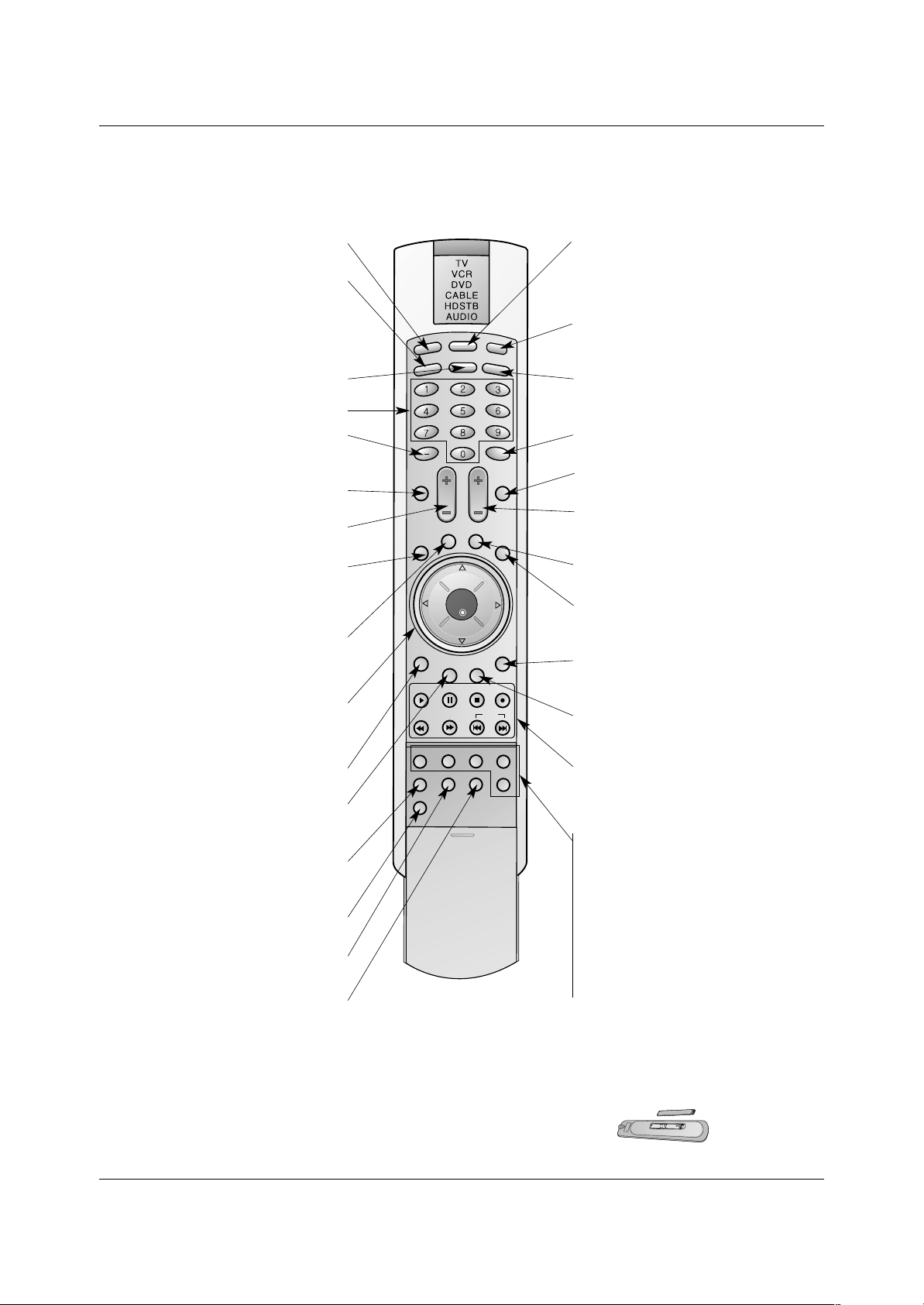
- When using the remote control, aim it at the remote control sensor on the TV.
LIGHT
TV/VIDE
O
MODE
COMP/RGB/DVI
MUTE
SURF
VOL CH
INFO
SAP
RATIO
CC
MENU
SOUND VIDEO
EXIT
PLAY PAUSE STOP RECORD
PIP PIPCH- PIPCH+ PIPINPUT
FREEZE
ADJUST
ENTER
ZOOM SIGNAL SWAP
REW FF SKIP
POWER
TIM
ER
FLASHBK
LIGHT
Illuminates the remote control buttons.
TV/VIDEO
Selects: DTV, Analog, Video1-2,
Component 1-2, RGB-DTV (or RGB-PC),
DVI-DTV (or DVI-PC) input sources.
COMP/RGB/DVI
Selects: Component 1-2, RGB-DTV (or RGB-
PC), DVI-DTV (or DVI-PC) input sources.
NUMBER buttons
DASH
Used to enter a program number for multiple
program channels such as 2-1,2-2,etc.
MUTE
Switches the sound on or off.
VCR/DVD BUTTONS
Control some video cassette recorders or
DVD player ("RECORD" button is not available for DVD player).
RATIO
Changes the aspect ratio.
MODE
Selects the remote operating mode: TV,
VCR, DVD, CABLE, HDSTB or AUDIO.
Select other operating modes, for the
remote to operate external devices.
POWER
Turns your TV or any other programmed
equipment on or off, depending on mode.
TIMER
Lets you select the amount of time before
your TV turns itself off automatically.
SURF
Use to scroll the Surf channel list.
CC
Select a closed caption:
Off, EZ Mute, and On.
FLASHBK
Tunes to the last channel viewed.
THUMBSTICK (Up/Down/Left/Right/ENTER)
Allows you to navigate the on-screen
menus and adjust the system settings to
your preference.
CHANNEL UP/DOWN
Selects available channels found
with EZ scan.
EXIT
Clears all on-screen displays and returns to
TV viewing from any menu.
VIDEO
Adjusts the factory preset picture according
to the room.
VOLUME UP/DOWN
Increases/decreases the sound level.
SAP
Selects MTS sound: Mono, Stereo, and SAP.
Change the audio language in DTV mode.
MENU
Brings up the main menu to the screen.
INFO
When you watch the TV, displays information
on top of the screen. Not available in
Component 1-2, RGB and DVI mode.
SOUND
Selects the sound appropriate
for the program's character.
PIP
Switches between PIP, POP (Picture-out-ofPicture) and Twin picture modes.
PIPCH-/PIPCH+
Changes to next higher/lower PIP channel.
PIP INPUT
Selects the input source for the sub picture.
SWAP
Exchanges the PIP/main images.
FREEZE
Freezes the currently-viewed picture. Main
picture is frozen in PIP/Twin picturre mode.
ADJUST
Adjusts screen position, clock, and
phase in PC mode.
ZOOM
Enlarges the main picture size.
SIGNAL
Displays the digital signal strength.
Installing Batteries
• Open the battery compartment cover on the back side and install the batteries
matching correct polarity (+ with +, - with -).
• Install two 1.5V AAbatteries. Don’t mix old or used batteries with new ones.
Replace cover.
Remote Control Key Functions
Remote Control Key Functions
9
Installation
Installation
Installation
Owner’s Manual
1.5V
1.5V
Batteries
Power Cord
L
I
G
H
T
T
V
/
V
I
D
E
O
MODE
COMP/RGB/DVI
MUTE
SURF
VOL CH
INFO
SAP
RATIO
CC
MENU
SOUNDVIDEO
EXIT
PLAY PAUSE STOPRECORD
PIP PIPCH- PIPCH+PIPINPUT
FREEZE
ADJUST
ENTER
ZOOM SIGNALSWAP
REW FF SKIP
P
O
W
E
R
T
IM
E
R
FLASHBK
Remote Control
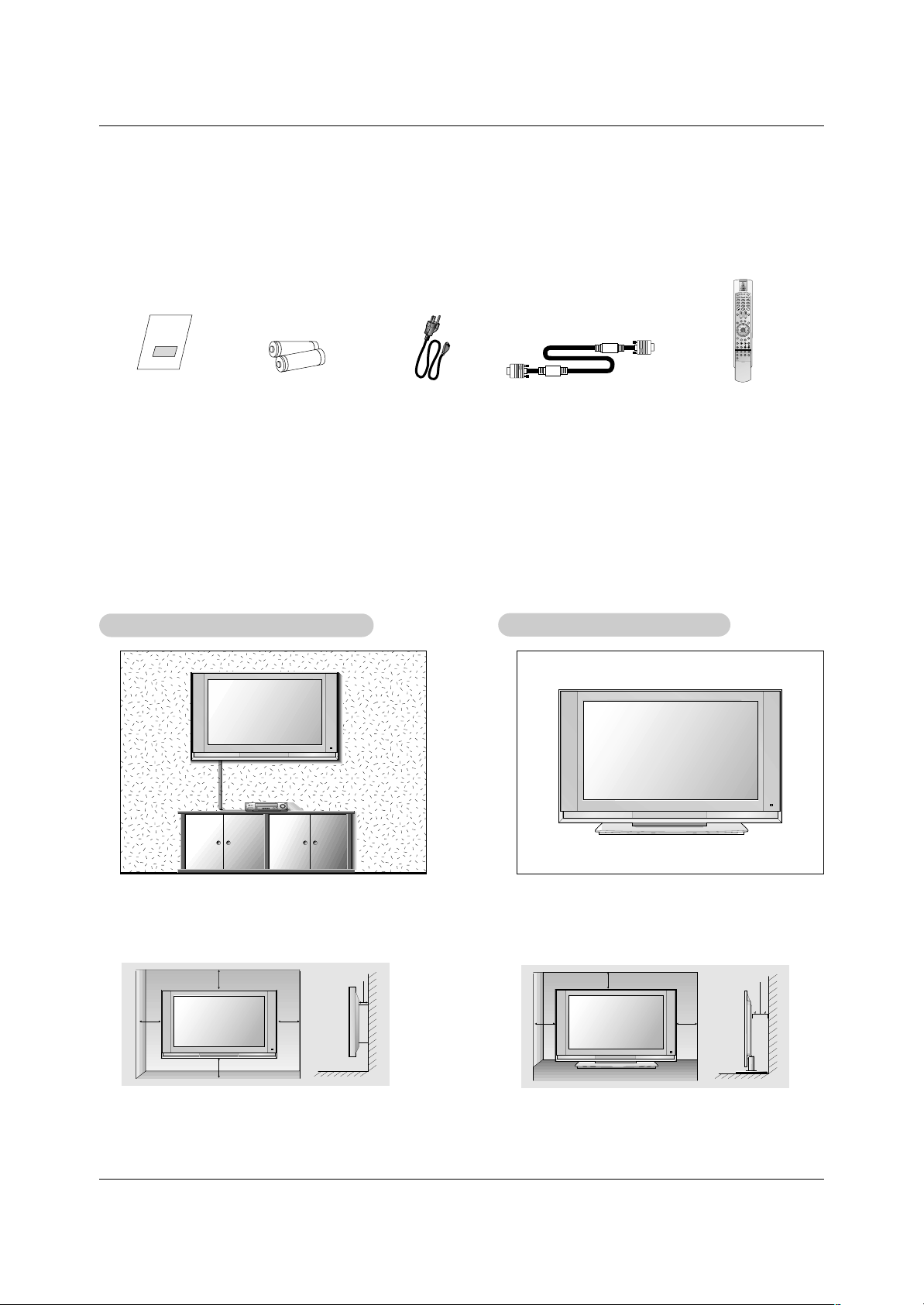
Ensure that the following accessories are included with your plasma display. If an accessory is missing, please contact the dealer
where you purchased the product.
WWall Mount: Horizontal installation
all Mount: Horizontal installation
For proper ventilation, allow a clearance of 4” on each
side and 2” from the wall. Detailed installation instructions are available from your dealer, see the optional
Wall Mounting Bracket Installation and Setup Guide.
Desktop Pedestal Installation
Desktop Pedestal Installation
For proper ventilation, allow a clearance of 4” on each
side and the top, 2.36” on the bottom, and 2” from the
wall. Detailed installation instructions are included in
the optional Desktop Stand Installation and Setup
Guide available from your dealer.
D-sub 15 pin Cable
Installation Instruction
Installation Instruction
4 inches
4 inches4 inches
4 inches
2 inches
4 inches
4 inches4 inches
2 inches
10
Installation
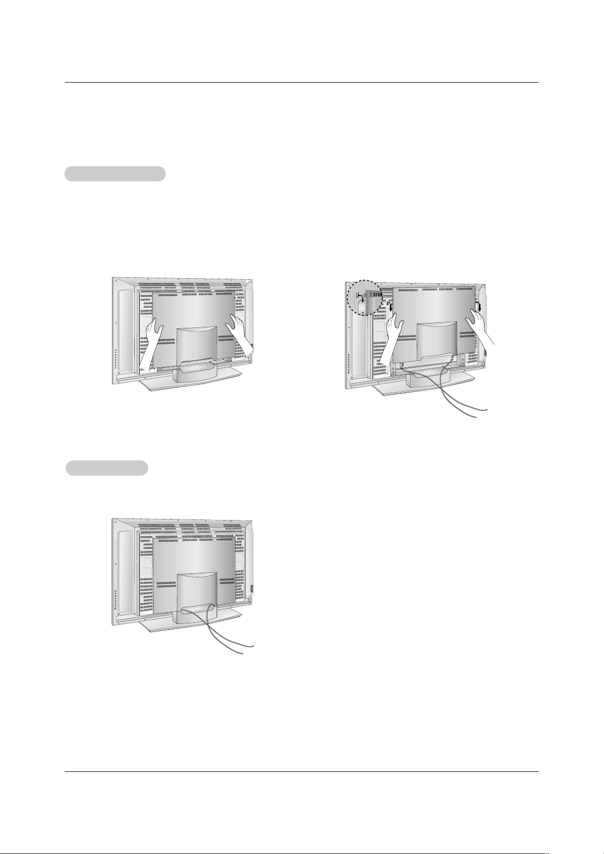
WWire Holders
ire Holders
- Thread, then pull the wires through the hole on the TV stand.
Rear
Rear
A/V Cover
A/V Cover
* The connection panel is hidden behind the A/V cover.
a. Remove the cover.
b. Install wires as necessary.
c. Reinstall the cover. Position the A/V cover with the TV back panel.
d. Align the holes on the TV back panel with the two tuberance on the rear A/V cover and insert.
e. Close cover.
Installation Instruction
Installation Instruction
- This manual explains the features available on the DU-42LZ30 TVs.
11
Installation
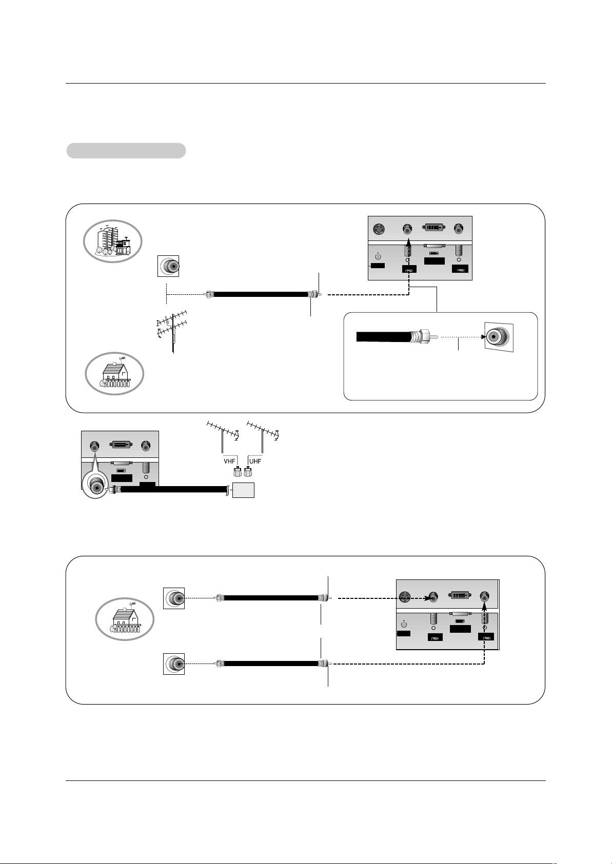
- Antenna or Cable Service without a Cable Box Connections
- For optimum picture quality, adjust antenna direction if needed.
Antenna Connection
Antenna Connection
Analog and Digital TV signals provided on one antenna
NOTE: If you are not sure of the type of signal(s) you are receiving, let EZ Scan complete all the channel signal-type searches.
The TV will let you know when the analog, cable, and digital channel scans are complete.
Analog and Digital TV signals provided on two separate antennas
• In a poor signal area to improve picture quality, purchase
and install a signal amplifier.
• If the antenna needs to be split for two TV’s, install a “2Way Signal Splitter” in the connections.
• If the antenna is not installed properly, contact your dealer for assistance.
Antenna1
Antenna 2
DVI INPUT
(PC/DTV INPUT)
Multi-family Dwellings/Apartments
(Connect to wall antenna socket)
Single-family Dwellings /Houses
(Connect to wall jack for outdoor antenna)
Outdoor
Antenna
Wall Antenna
Socket
VHF Antenna
UHF Antenna
RF Coaxial Wire (75 ohm)
Bronze Wire
Turn clockwise to tighten.
Bronze Wire
Be careful not to bend the bronze wire when
connecting the antenna.
Antenna1
Antenna 2
S-VIDEO
DVI INPUT
(PC/DTV INPUT)
Wall Antenna
Socket
RF Coaxial Wire (75 ohm)
Analog Antenna
Digital Antenna
Bronze Wire
Bronze Wire
Turn clockwise to tighten.
Wall Antenna
Socket
RF Coaxial Wire (75 ohm)
External Equipment Connections
External Equipment Connections
S-VIDEO
Antenna1
DVI INPUT
(PC/DTV INPUT)
Antenna 2
Signal
Amplifier
12
Installation
NOTE: All cables shown are not included with the TV
- To avoid picture noise (interference), leave an adequate distance between the VCR and TV
- Typically a frozen still picture from a VCR. If the 4:3 picture format is used; the fixed images on the sides of the screen may
remain visible on the screen.
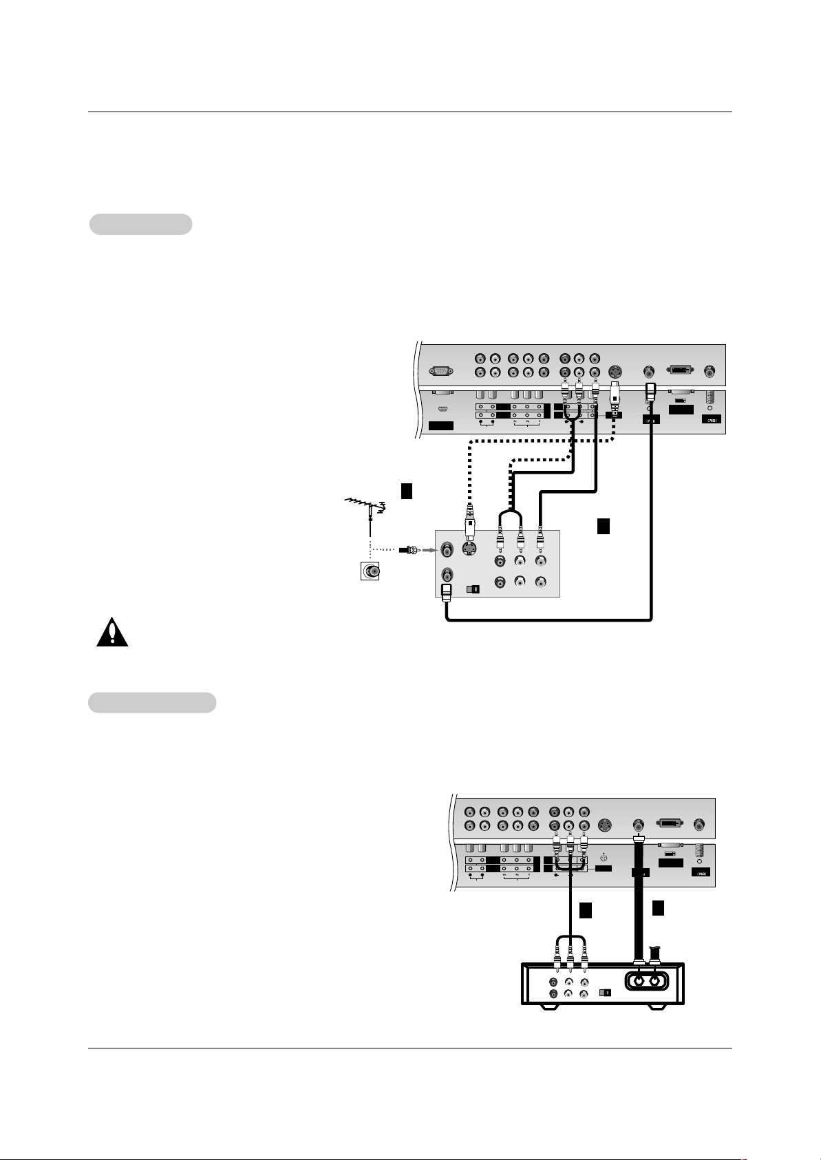
Connection Option 1
Set VCR output switch to 3 or 4 and then tune
TV to the same channel number.
Connection Option 2
1. Connect the audio and video cables from the
VCR's output jacks to the TV input jacks, as
shown in the figure.
When connecting the TV to VCR, match the
jack colors (Video = yellow, Audio Left = white,
and Audio Right = red).
If you connect an S-VIDEO output from VCR to
the S-VIDEO input, the picture quality is
improved; compared to connecting a regular
VCR to the Video input.
2. Insert a video tape into the VCR and press
PLAY on the VCR. (Refer to the VCR owner ’s
manual.)
3. Select the input source with using the
TV/VIDEO button on the remote control. (If
connected to A/V INPUT 1, select Video 1
input source)
Do not connect to both Video and
S-Video at the same time.
VCR Setup
VCR Setup
Antenna1
Antenna 2
S-VIDEO
RGB INPUT
(PC/DTV INPUT)
DVI INPUT
(PC/DTV INPUT)
AUDIO INPUT
AUDIO VIDEO
VIDEO INPUT
COMPONENT 2
MONITOR
OUTPUT
A/V
INPUT1
(MONO)
DVD
/DTV
INPUT
COMPONENT 1
RL
R L
S-VIDEO
OUT
IN
(R) AUDIO (L) VIDEO
34
OUTPUT
SWITCH
ANT OUT
ANT IN
- After subscribing to a cable TV service from a local provider and installing a converter, you can watch cable TV programming.
The TV cannot display TV programming unless a TV tuner device or cable TV converter box is connected to the TV.
- For further information regarding cable TV service, contact your local cable TV service provider(s).
Connection Option 1
1. Select 3 or 4 with channel switch on cable box.
2. Tune the TV channel to the same selected output channel on
cable box.
3. Select channels at the cable box or with the cable box remote
control.
Connection Option 2
1. Connect the audio and video cables from the Cable Box's output
jacks to the TV input jacks, as shown in the figure.
When connecting the TV to a Cable Box, match the jack colors
(Video = yellow, Audio Left = white, and Audio Right = red).
2. Select the input source with using the TV/VIDEO button on the
remote control. (If connected to A/V INPUT 1, select Video 1 input
source)
3. Select your desired channel with the remote control for cable box.
Cable
Cable
TV Setup
TV Setup
Antenna1
Antenna 2
S-VIDEO
DVI INPUT
(PC/DTV INPUT)
AUDIO INPUT
AUDIO VIDEO
VIDEO INPUT
COMPONENT 2
MONITOR
OUTPUT
A/V
INPUT1
(MONO)
DVD
/DTV
INPUT
COMPONENT 1
RL
R L
TV
VCR
RF Cable
(R) AUDIO (L) VIDEO
34
OUTPUT
SWITCH
VCR
Cable Box
1
2
1
2
13
Installation
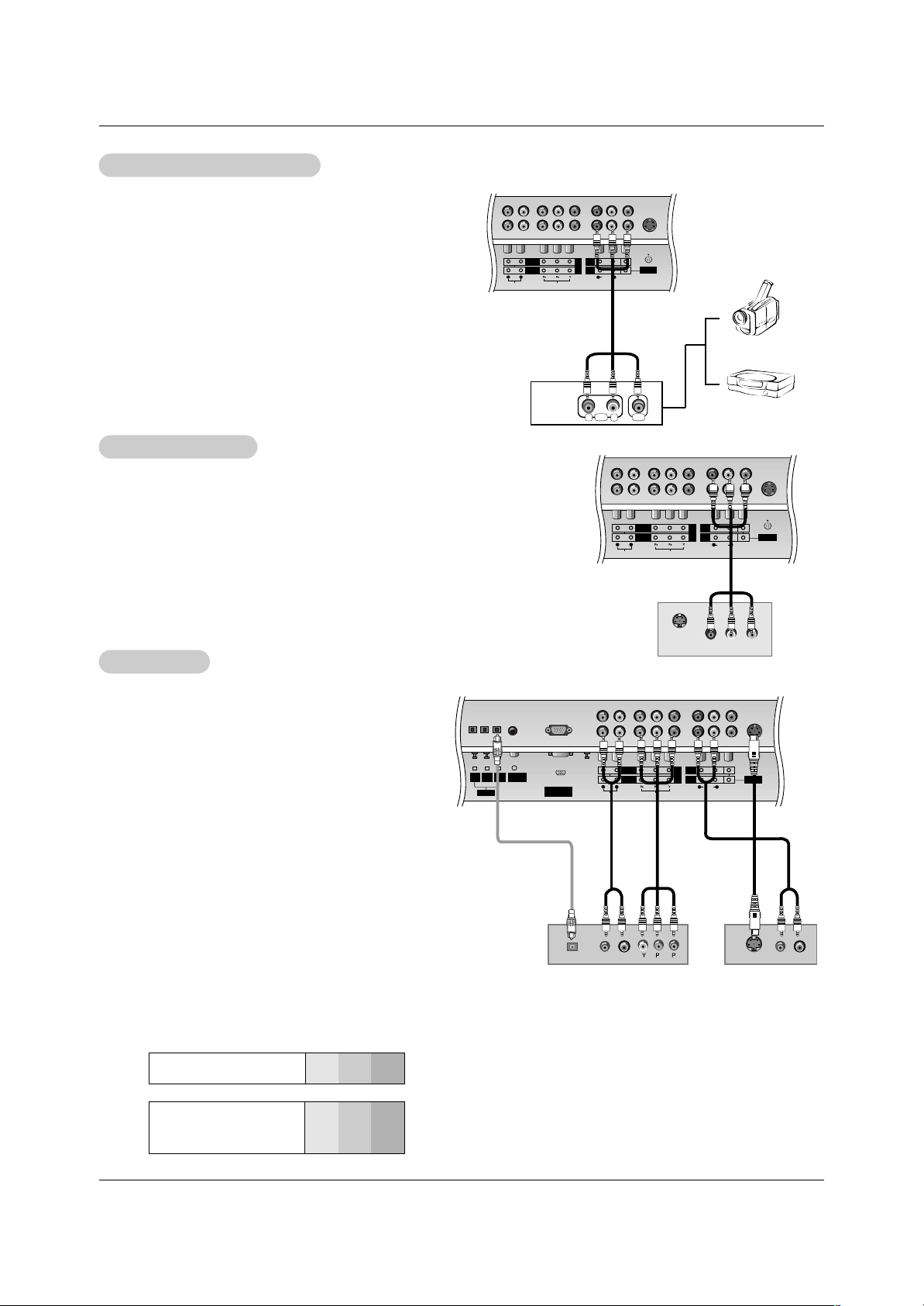
• Component Input ports
To get better picture quality, connect a DVD player
to the component input ports as shown below.
How to connect
Connect the audio and video cables from the external equipment's output jacks to the TV input jacks, as shown in the
figure.
When connecting the TV to external equipment, match the
jack colors (Video = yellow, Audio Left = white, and Audio
Right = red).
How to use
1. Select the input source with using the TV/VIDEO button on
the remote control. (If connected to A/V INPUT 1, select
Video 1 input source).
2. Operate the corresponding external equipment. Refer to
external equipment operating guide.
Component ports
on the TV
Y
PB
PR
Video output ports
on DVD player
Y
Y
Y
Y
Pb
B-Y
Cb
PB
Pr
R-Y
Cr
P
R
How to connect
1. Connect the DVD video outputs (Y, PB, PR) to the COM-
PONENT (Y, P
B
, PR) INPUT jacks on the TV and connect
the DVD audio outputs to the AUDIO INPUT jacks on the
TV, as shown in the figure.
2. If your DVD only has an S-Video output jack, connect this
to the S-VIDEO input on the TV and connect the DVD
audio outputs to the AUDIO INPUT jacks on the TV, as
shown in the figure.
NOTE: If your DVD player does not have component video
output, use S-Video.
How to use
1. Turn on the DVD player, insert a DVD.
2. Use the TV/VIDEO or COMP/RGB/DVI button on the
remote control to select Component 1 or Component 2.
(If connected to S-VIDEO, select the Video 1 or Video 2
external input source.)
3. Refer to the DVD player's manual for operating instructions.
External
External
A/V Source Setup
A/V Source Setup
DVD Setup
DVD Setup
S-VIDEO
AUDIO INPUT
AUDIO VIDEO
VIDEO INPUT
COMPONENT 2
MONITOR
OUTPUT
A/V
INPUT1
(MONO)
DVD
/DTV
INPUT
COMPONENT 1
RL
R L
RL
AUDIO VIDEO
S-VIDEO
RGB INPUT
(PC/DTV INPUT)
AUDIO INPUT
AUDIO VIDEO
VIDEO INPUT
DIGITAL AUDIO
(OPTICAL)
COMPONENT 2
MONITOR
OUTPUT
A/V
INPUT1
(MONO)
DVD
/DTV
INPUT
COMPONENT 1
DVI
INPUT
PC/DVI
AUDIO INPUT
RL
R L
COMPONENT1
INPUT
OUTPUT
B
R
(R) AUDIO (L)
DIGITAL AUDIO
OPTICAL
(R) AUDIO (L)
S-VIDEO
DVD
or
Camcorder
Video Game Set
The TV has a special signal output capability which allows you to hook up a second TV or monitor.
Connect the second TV or monitor to the TV’s MONITOR OUTPUT. See the
Operating Manual of the second TV or monitor for further details regarding that
device’s input settings.
NOTE
• Component, RGB-PC/RGB-DTV, DVI-PC/DVI-DTV, DTV input sources cannot
be used for Monitor out.
NOTES
• Digital Audio will not work for Component 2 input source.
• Digital Audio operation has priority if Digital Audio and AUDIO L/R
are connected at the same time.
S-VIDEO
IN
(R) AUDIO (L) VIDEO
S-VIDEO
AUDIO INPUT
AUDIO VIDEO
VIDEO INPUT
COMPONENT 2
MONITOR
OUTPUT
A/V
INPUT1
(MONO)
DVD
/DTV
INPUT
COMPONENT 1
RL
R L
Monitor Out Setup
Monitor Out Setup
or
14
Installation
Send the TV’s audio to external audio equipment (stereo system) via
the Digital Audio Output Optical port.
How to connect
1. Connect one end of an optical cable to the TV Digital Audio Optical
Output port.
2. Connect the other end of the optical cable to the digital audio optical
input on the audio equipment.
3. Set the “ TV Speaker option - Off” in the AUDIO menu. Refer to
page 23.
See the external audio equipment instruction manual for operation.
Caution: Do not look into the optical output port.
Looking at the laser beam may damage
your vision.
Digital
Digital
Audio Output
Audio Output
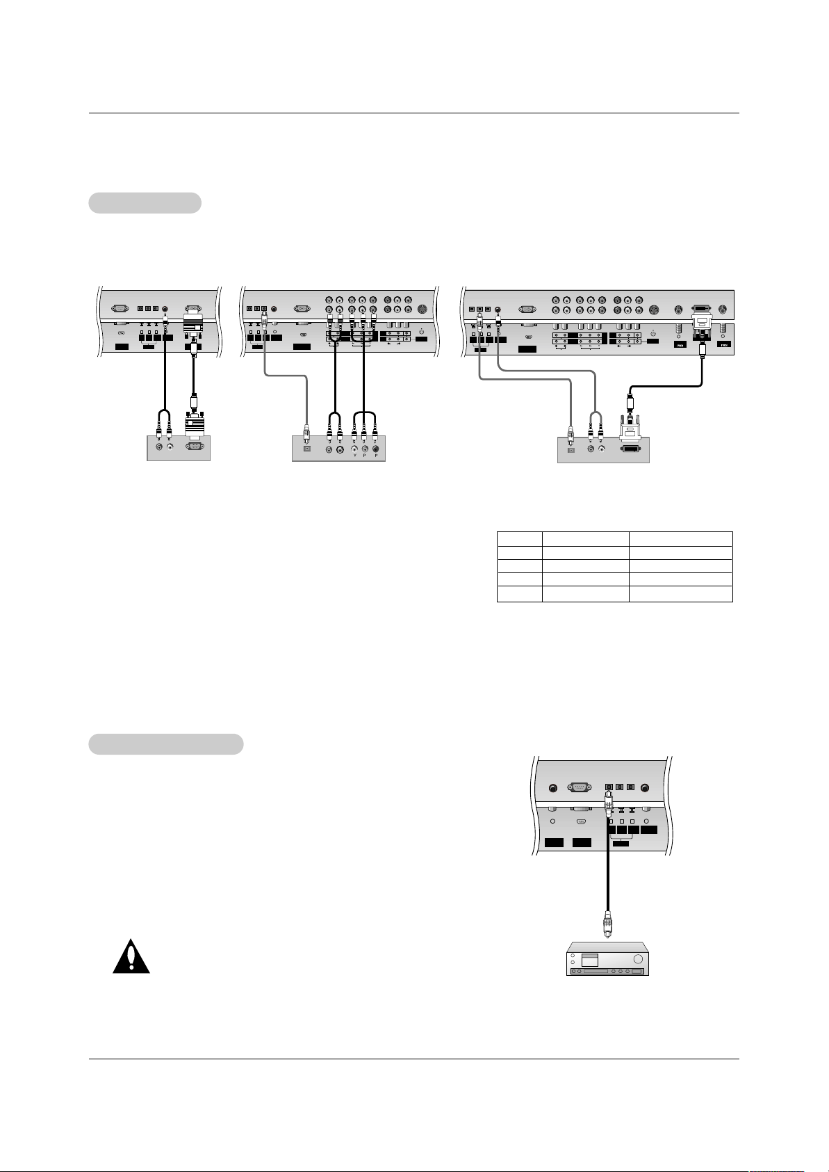
- This TV can receive Digital Over-the-air/Cable signals without an external digital set-top box. However, if you do receive Digital
signals from a digital set-top box or other digital external device, refer to the figure as shown below.
- This TV supports HDCP (High-bandwidth Digital Contents Protection) protocol for DTV (480p,720p,1080i) mode.
How to connect
Use the TV’s COMPONENT (Y, PB, PR) INPUT, RGB or DVI jack for
video connections, depending on your set-top box connector. Then,
make the corresponding audio connections.
How to use
1. Turn on the digital set-top box. (Refer to the owner’s manual for the
digital set-top box.)
2. Use TV/VIDEO or COMP/RGB/DVI on the remote control to select
Component 1, Component 2, RGB-DTV, or DVI-DTV source.
HDSTB Setup
HDSTB Setup
UPGRADE
PORT
RGB INPUT
(PC/DTV INPUT)
DIGITAL AUDIO
(OPTICAL)
DVI
INPUT
PC/DVI
AUDIO INPUT
COMPONENT1
INPUT
OUTPUT
S-VIDEO
RGB INPUT
(PC/DTV INPUT)
AUDIO INPUT
AUDIO VIDEO
VIDEO INPUT
DIGITAL AUDIO
(OPTICAL)
COMPONENT 2
MONITOR
OUTPUT
A/V
INPUT1
(MONO)
DVD
/DTV
INPUT
COMPONENT 1
DVI
INPUT
PC/DVI
AUDIO INPUT
RL
R L
COMPONENT1
INPUT
OUTPUT
B
R
(R) AUDIO (L)
(R) AUDIO (L)
RGB-DTV OUTPUT
DIGITAL AUDIO
OPTICAL
Antenna1
Antenna 2
S-VIDEO
RGB INPUT
(PC/DTV INPUT)
DVI INPUT
(PC/DTV INPUT)
AUDIO INPUT
AUDIO VIDEO
VIDEO INPUT
DIGITAL AUDIO
(OPTICAL)
COMPONENT 2
MONITOR
OUTPUT
A/V
INPUT1
(MONO)
DVD
/DTV
INPUT
COMPONENT 1
DVI
INPUT
PC/DVI
AUDIO INPUT
RL
R L
COMPONENT1
INPUT
OUTPUT
(R) AUDIO (L)
DVI-DTV OUTPUT
DIGITAL AUDIO
OPTICAL
Digital Set-top Box
or
or
or
or
REMOTE
CONTROL
UPGRADE
PORT
DIGITAL AUDIO
(OPTICAL)
DVI
INPUT
PC/DVI
AUDIO INPUT
COMPONENT1
INPUT
OUTPUT
Signal
480i
480p
720p
1080i
Component 1/2
Yes
Yes
Yes
Yes
RGB-DTV,DVI-DTV
No
Yes
Yes
Yes
15
Installation
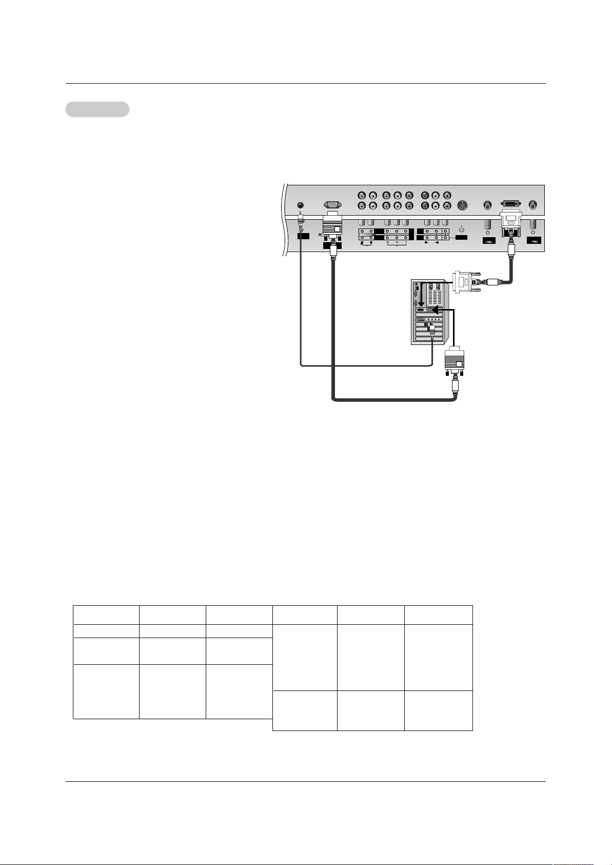
How to connect
1. To get the best picture quality, adjust the PC
graphics card to 1024x768, 60Hz.
2. Use the TV’s RGB INPUT or DVI (Digital Visual
Interface) INPUT port for video connections,
depending on your PC connector.
• If the graphic card on the PC does not output
analog and digital RGB simultaneously, connect
only one of either RGB INPUT or DVI INPUT to
display the PC on the TV.
• If the graphic card on the PC does output analog
and digital RGB simultaneously, set the TV to
either RGB or DVI; (the other mode is set to Plug
and Play automatically by the TV.)
3. Then, make the corresponding audio connections.
If using a sound card, adjust the PC sound as
required.
How to use
1. Turn on the PC and the TV.
2. Turn on the display by pressing the POWER button on the TV's remote control.
3. Select RGB-PC or DVI-PC input source in main input option of SETUP menu. (Refer to P.20)
4. Check the image on your TV. There may be noise associated with the resolution, vertical pattern, contrast or brightness in PC mode. If noise is present, change the PC mode to another resolution, change the refresh rate to another
rate or adjust the brightness and contrast on the menu until the picture is clear. If the refresh rate of the PC graphic
card can not be changed, change the PC graphic card or consult the manufacturer of the PC graphic card.
NOTES: • Depending on the graphics card, DOS mode may not work if you use a DVI-I cable.
• Avoid keeping a fixed image on the TV's screen for a long period of time. The fixed image may become per-
manently imprinted on the screen. Use the Orbiter screen saver when possible.
• The synchronization input form for Horizontal and Vertical frequencies is separate.
PC Setup
PC Setup
Antenna1
Antenna 2
S-VIDEO
RGB INPUT
(PC/DTV INPUT)
DVI INPUT
(PC/DTV INPUT)
AUDIO INPUT
AUDIO VIDEO
VIDEO INPUT
COMPONENT 2
MONITOR
OUTPUT
A/V
INPUT1
(MONO)
DVD
/DTV
INPUT
COMPONENT 1
RL
R L
PC/DVI
AUDIO INPUT
- This TV provides Plug and Play capability, meaning that the PC adjusts automatically to the TV's settings. The TV sends config-
uration information (EDID) to the PC using the Video Electronics Standard Association (VESA) Display Data Channel (DDC)
protocol.
- The TV perceives 640x480, 60Hz as DTV 480p based on the PC graphic card. card, change the screen scanning rate for the
graphic card accordingly.
Resolution
640x350
720x400
640x480
800x600
Horizontal
Frequency(KHz)
31.468
31.469
37.927
31.469
37.861
37.500
43.269
70.09
70.08
85.03
59.94
72.80
75.00
85.00
35.156
37.879
48.077
46.875
53.674
48.363
56.476
60.023
56.25
60.31
72.18
75.00
85.06
60.00
70.06
75.02
Vertical
Frequency(Hz)
Resolution
Horizontal
Frequency(KHz)
Vertical
Frequency(Hz)
1024x768
Monitor Display Specifications (RGB-PC / DVI-PC Mode)
 Loading...