

LG DPDP60, MU60PZ10B Service Manual
SERVICE MANUAL
Product Type: PLASMA
Manual Part#: 923-03464
Chassis: PDP 60”
Product Year: 2001
Service Manual is a part the Service Kit. Manual is to remain with Service Kit.
OVERVIEW ........................................................ 5
TROUBLESHOOTING .............................................8
SERVICING ...................................................... 12
PARTS ............................................................ 16
DIAGRAMS ...................................................... 17
Model Series:
DPDP60
MU60PZ10B
CONTENTS
Made/Printed
in the U.S.A. R1
Published by Technical Publications
LG & Zenith Electronics Corporation
P.O. Box 240007
Huntsville, Alabama 35824
Copyright October 2001 by LG & Zenith Electronics Corporation
PRODUCT SAFETY GUIDELINES
IMPORTANT SAFETY NOTICE
This manual was prepared for use only by properly trained audio-visual service
technicians.
When servicing this product, under no circumstances should the original
design be modified or altered without permission from Zenith Electronics
Corporation. All components should be replaced only with types identical to
those in the original circuit and their physical location, wiring and lead dress
must conform to original layout upon completion of repairs.
Special components are also used to prevent x-radiation, shock and fire hazard.
These components are indicated by the letter “x” included in their component
designators and are required to maintain safe performance. No deviations are
allowed without prior approval by Zenith Electronics Corporation.
Circuit diagrams may occasionally differ from the actual circuit used. This way,
implementation of the latest safety and performance improvement changes into
the set is not delayed until the new service literature is printed.
CAUTION: Do not attempt to modify this product in any way. Never perform
customized installations without manufacturer’s approval. Unauthorized
modifications will not only void the warranty, but may lead to property damage
or user injury.
Service work should be performed only after you are thoroughly familiar with
these safety checks and servicing guidelines.
GRAPHIC SYMBOLS
The exclamation point within an equilateral triangle is intended
to alert the service personnel to important safety information in
the service literature.
The lightning flash with arrowhead symbol within an equilateral
triangle is intended to alert the service personnel to the presence
of noninsulated “dangerous voltage” that may be of sufficient
magnitude to constitute a risk of electric shock.
The pictorial representation of a fuse and its rating within an
equilateral triangle is intended to convey to the service personnel
the following fuse replacement caution notice:
CAUTION: FOR CONTINUED PROTECTION AGAINST RISK OF FIRE,
REPLACE ALL FUSES WITH THE SAME TYPE AND RATING AS MARKED
NEAR EACH FUSE.
SERVICE INFORMATION
While servicing, use an isolation transformer for protection from AC line shock.
After the original service problem has been corrected, make a check of the
following:
FIRE AND SHOCK HAZARD
1. Be sure that all components are positioned to avoid a possibility of
adjacent component shorts. This is especially important on items transported to and from the repair shop.
2. Verify that all protective devices such as insulators, barriers, covers,
shields, strain reliefs, power supply cords, and other hardware have been
reinstalled per the original design. Be sure that the safety purpose of the
polarized line plug has not been defeated.
3. Soldering must be inspected to discover possible cold solder joints, solder
splashes, or sharp solder points. Be certain to remove all loose foreign
particles.
4. Check for physical evidence of damage or deterioration to parts and components, for frayed leads or damaged insulation (including the AC cord), and
replace if necessary.
5. No lead or component should touch a receiving tube or a resistor rated at
1 watt or more. Lead tension around protruding metal surfaces must be
avoided.
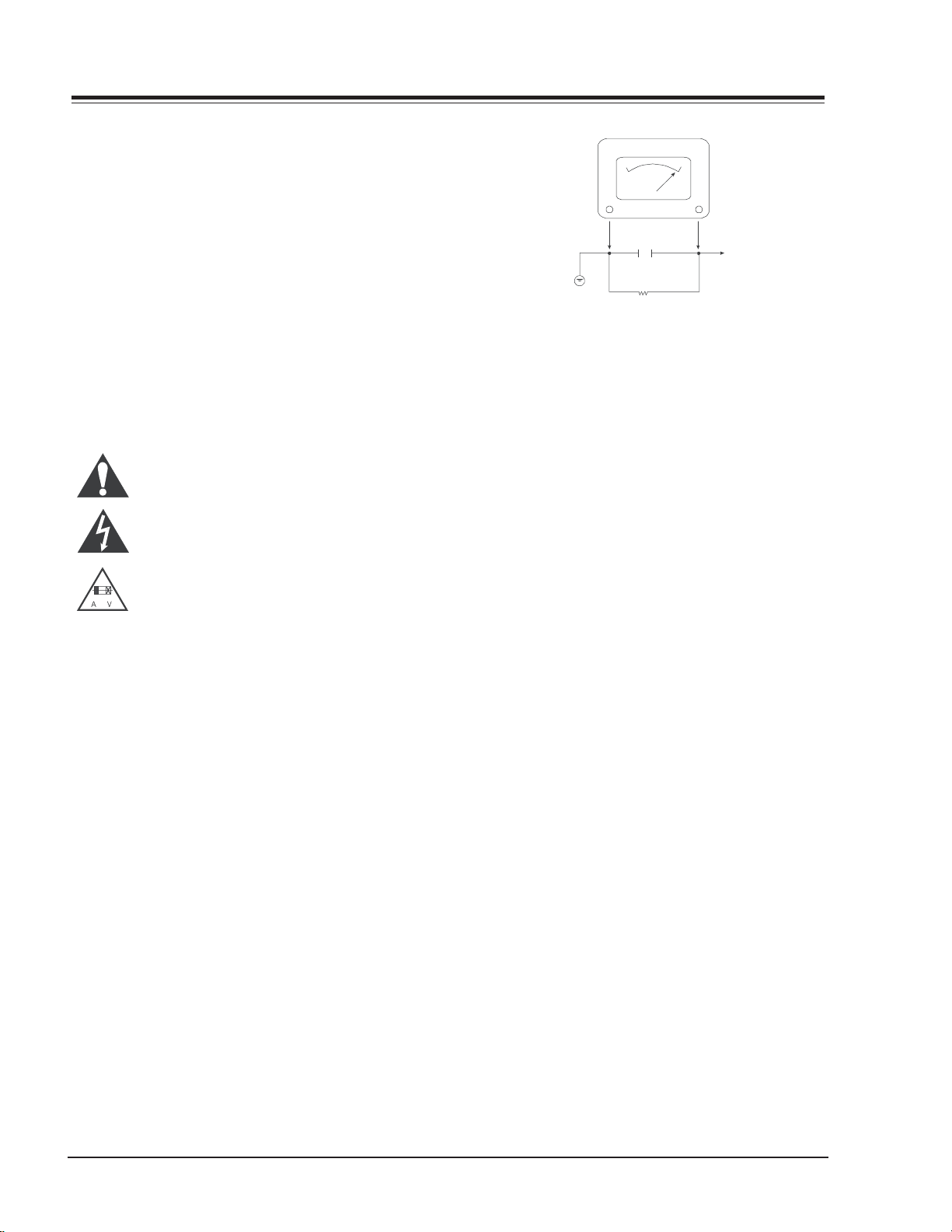
6. After reassembly of the set, always perform an AC leakage test on all exposed
metallic parts of the cabinet (the channel selector knobs, antenna terminals,
handle and screws) to be sure that set is safe to operate without danger of
electrical shock. DO NOT USE A LINE ISOLATION TRANSFORMER DURING THIS
TEST. Use an AC voltmeter having 5000 ohms per volt or more sensitivity in
the following manner: Connect a 1500 ohm, 10 watt resistor, paralleled by
a .15 mfd 150V AC type capacitor between a known good earth ground
water pipe, conduit, etc.) and the exposed metallic parts, one at a time.
Measure the AC voltage across the combination of 1500 ohm resistor and
.15 mfd capacitor. Reverse the AC plug by using a non-polarized adaptor
and repeat AC voltage measurements for each exposed metallic part. Voltage
measured must not exceed 0.75 volts RMS. This corresponds to 0.5 milliamp
AC. Any value exceeding this limit constitutes a potential shock hazard and
must be corrected immediately.
A.C. Voltmeter
Good Earth Ground
such as the Water
Pipe, Conduit, etc.
0.15uF
1500 OHM
10 WATT
Place this probe
on each exposed
metal part.
X-RADIATION
1. Be sure procedures and instructions to all service personnel cover the
subject of x-radiation. The only potential source of x-rays in current TV
receivers is the picture tube. However, this tube does not emit x-rays when
the HV is at the factory-specified level. The proper value is given in the
applicable schematic. Operation at higher voltages may cause a failure of
the picture tube or high-voltage supply and, under certain circumstances
may produce radiation in excess of desirable levels.
2. Only factory-specified CRT anode connectors must be used.
3. It is essential that the service personnel have available an accurate and
reliable high-voltage meter.
4. When the high-voltage circuitry is operating properly, there is no possibility
of an x-radiation problem. Every time a color chassis is serviced, the
brightness should be run up and down while monitoring the high voltage
with a meter, to be certain that the high voltage does not exceed the
specified value and that it is regulating correctly.
5. When troubleshooting and making test measurements in a product with a
problem of excessively high voltage, avoid being unnecessarily close to
the picture tube and the high voltage power supply. Do not operate the
product longer than necessary to locate the cause of excessive voltage.
6. Refer to HV, B+, and shutdown adjustment procedures described in the
appropriate schematics and diagrams (where used).
IMPLOSION
1. All direct view picture tubes are equipped with an integral implosion
protection system; take care to avoid damage during installation.
2. Use only the recommended factory replacement tubes.
TIPS ON PROPER INSTALLATION
1. Never install any receiver in a closed-in recess, cubbyhole, or closely
fitting shelf space over, or close to, a heat duct, or in the path of heated
air flow.
2. Avoid conditions of high humidity such as: outdoor patio installations
where dew is a factor, near steam radiators where steam leakage is a factor,
etc.
3. Avoid placement where draperies may obstruct venting. The customer
should also avoid the use of decorative scarves or other coverings that
might obstruct ventilation.
4. Wall- and shelf-mounted installations using a commercial mounting kit
must follow the factory-approved mounting instructions. A product mounted
to a shelf or platform must retain its original feet (or the equivalent
thickness in spacers) to provide adequate air flow across the bottom. Bolts
or screws used for fasteners must not touch any parts or wiring. Perform
leakage tests on customized installations.
5. Caution customers against mounting a product on a sloping shelf or in a
tilted position, unless the receiver is properly secured.
6. A product on a roll-about cart should be stable in its mounting to the cart.
Caution the customer on the hazards of trying to roll a cart with small
casters across thresholds or deep pile carpets.
7. Caution customers against using a cart or stand that has not been listed
by Underwriters Laboratories, Inc. for use with its specific model of
television receiver or generically approved for use with TVs of the same or
larger screen size.
8. Caution customers against using extension cords. Explain that a forest of
extensions, sprouting from a single outlet, can lead to disastrous
consequences to home and family.
2 PDP 60” - SAFETY

TABLE OF CONTENTS
OVERVIEW ........................................................5
SPECIFICATIONS .............................................5
CONNECTIONS/CONTROLS ..................................6
REMOTE ........................................................7
TROUBLESHOOTING ...........................................8
NO POWER ..................................................... 8
ABNORMAL PICTURE .......................................8
NO SOUND ................................................... 11
ADJUSTMENT INSTRUCTIONS ............................. 10
PRECAUTIONS .............................................. 1 0
VOLTAGE ADJUSTMENTS .................................10
RGB CUTOFF ................................................ 10
COLOR TEMPERATURE .................................... 10
VIF VCO ...................................................... 11
AGC ........................................................... 11
OPTION TABLE.............................................. 11
PARTS ............................................................ 16
DIAGRAMS ..................................................... 17
EXPLODED VIEW ........................................... 17
INTERCONNECT ............................................. 18
PHOTO / MODULE LAYOUT .............................. 19
BLOCK DIAGRAMS ......................................... 20
VIDEO SCAN CONVERTER PCB TOP .................... 21
AC LINE FILTER / PRIMARY SUPPLY ................. 22
SWITCH MODE POWER SUPPLY......................... 23
3 PDP 60” - TOC


Overview
OVERVIEW
GENERAL INFO
SPECIFICATIONS
Screen Size 60 in/132 cm diagonal
Aspect Ratio 16:9 (width:height)
Resolution 1280 x 720 pixels
Peak Brightness 180cd/m (with 45%filter)
Contrast Ratio 330:1(Dark Room)
Viewing Angle 160° horizontally and vertically
Displayable Colors 16.77 million
Weight 154.3 lbs(MNT), 66.8 lbs(D/Stand), 5.5lbs(Spk.)x2
Life Approx. 25,000 hours
Dimensions(MNT) 75.3 in wide, 34.8 in high, 3.9 in deep
(SPK) 5.3 in wide, 34.8 in high, 3.9 in deep
Input Terminals RF terminal(NTSC)
Composite Video input(RCA) X 2, S-Video
Audio L&R input(RCA) X 2
Component Video (Y,Cb,Cr) + R/L for DVD
Component Video (Y,Pb,Pr)+ R/L for HDTV Stb.
RGB-SUB 15 pin for HDTV Stb.(480p/720p/1080i)
Analog RGB-SUB 15pin(PC VGA ~SVGA)
Stereo Input for PC Audio
Output Terminals RGB-SUB 15 pin(PC/DTV1 out : bypass)
Audio L&R(RCA) & Woofer Sound out(option)
Composite Video output + R/L output
Display Frequency 15.73kHz to 68kHz horizontally, 50Hz to 80Hz(V)
Picture DRP, Digital 3D Comb filter, LTI/CTI
Sound A2 stereo, Dolby Virtual, AVL, 2x10Wrms(woofer:opt.)
Remote Control Included(Unified)
Power Source 120V / 60 Hz
Power Consumption 320 watts( with Max. Audio : 330W)
*Designs and specifications are subject to change without notice.
*Weight and dimensions shown are approximate.
5 PDP 60” - OVERVIEW
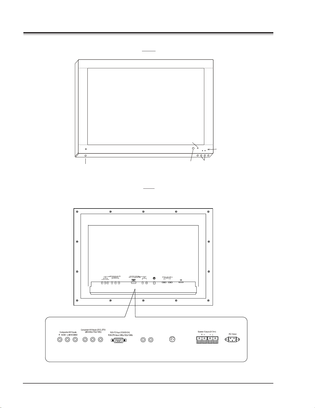
ON/OFF
OVERVIEW
FRONT
Input Select
INPUT VOLUME
SELECT
Sub Power
Main power button
PBRYP
Remote Control Sensor
BACK
S-Video
(+) ( ) (+)( )
½
Volume
AC INPUT
PBY
P
R
Audio Inputs
S-Video
(+) ( )
(+)( )
6 PDP 60” - OVERVIEW
OVERVIEW
.
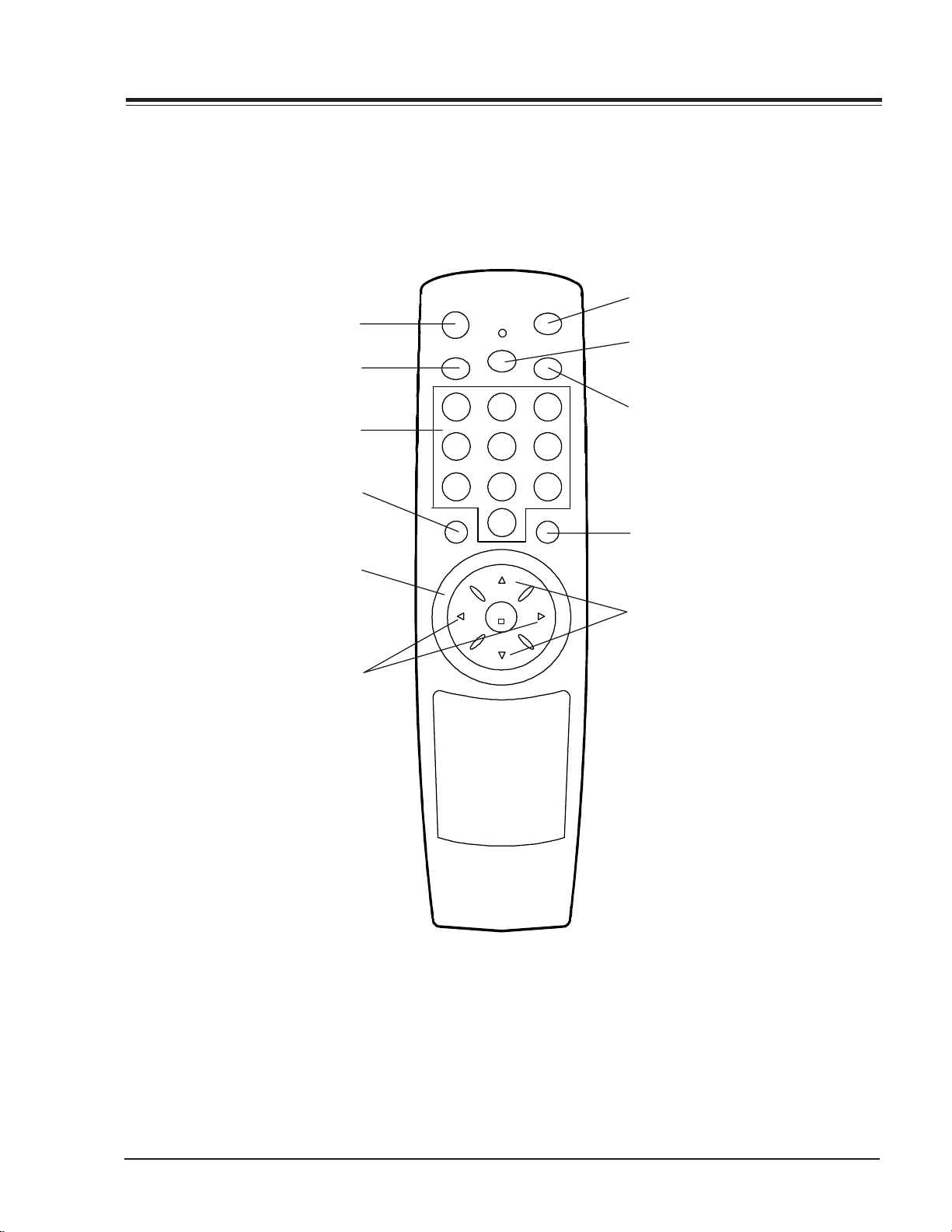
REMOTE
POWER ON
Toggles the on on and off.
MUTE
Toggles the sound on and off.
NUMBER PAD
Selects channels directly.
VIDEO PC
Toggles through available video
inputs. Composite, Component,
RGB-PC, & RGB-DTV
THUMBSTICK
Navigates the on-screen menus and
adjusts system settings and preferences.
Use the arrows to navigate menus and
press the center to select.
VOLUME UP/DOWN
Increases/decreases the sound level.
power on
mute
sleep
system off
CC
1 32
5
4 6
7 98
video/p c menu
0
up
enter
vol vol
down
SYSTEM OFF
Toggles the current component power on/off
SLEEP
Turns sound Off and On
while picture remains.
CC
Displays closed caption menu.
MENU
Displays menus and advances through the
different menus available.
CHANNEL (Up/Down)
Selects next channel in TV’s memory
or scrolls up/down in GUIDE Plus+ Gold.
Zenith Remote Part# 6710V00042H
LG Remote Part# 6710V00042K
7 PDP 60” - OVERVIEW
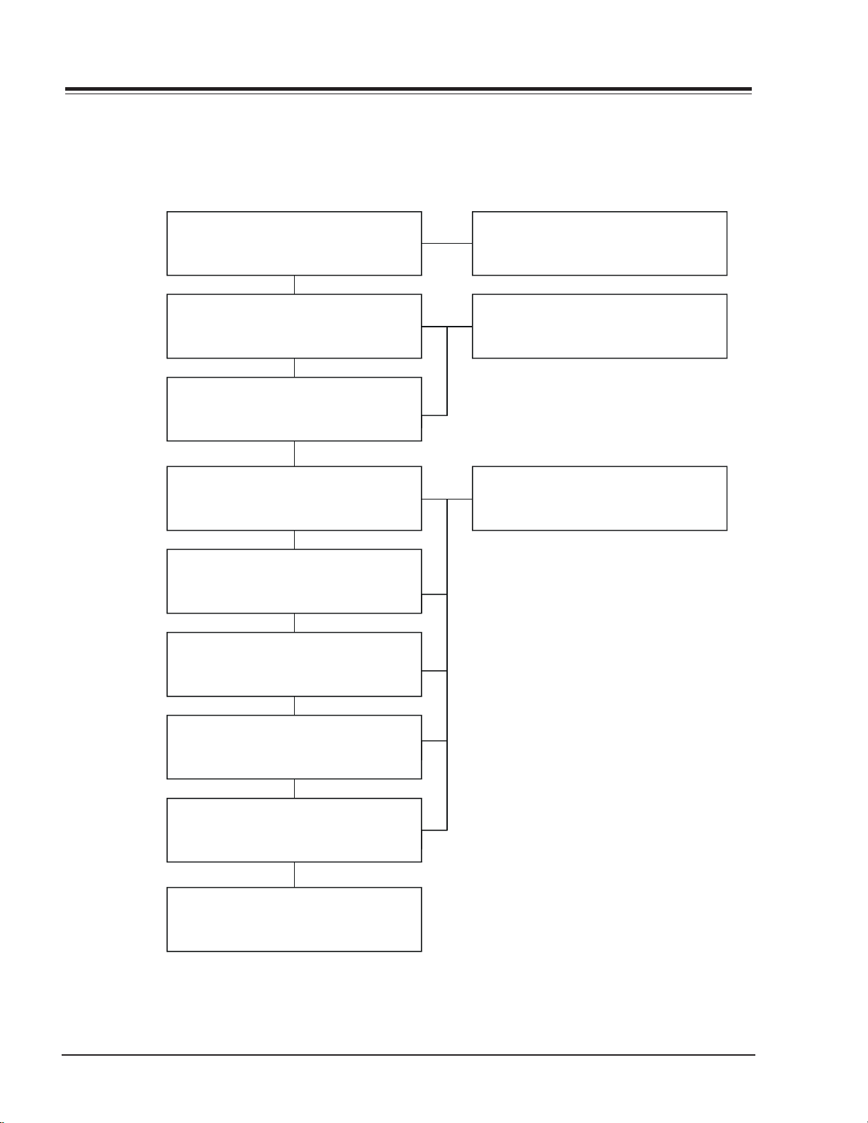
TROUBLESHOOTING
y
y
y
NO POWER
SERVICING
Is 5V ST-BY present on P805A pin 3?
YES
Is 24V present on P806A pin 1?
YES
Is 380V present on TP1?
YES
Is 12V present on P807B pin2?
YES
Is 17V present on P803B pin 1?
YES
NO
NO
NO
NO
NO
Replace PrimarySuppl
Replace PrimarySuppl
Replace Switch Mode Power Suppl
Is 25V present on P8011 pin 1?
YES
Is 75V present on P8012 pin 1?
YES
Is 180V present on P8012 pins 6,7,8, ?
YES
Replace Video Scann Converter.
NO
NO
NO
8 PDP 60” - SERVICING
 Loading...