

Page 1
Adjustment and Test procedure Manual
for digital multimeter
Model: DM-341
LG Precision Co., Ltd.
1999/9/1 P/N:
Page 2
Adjustment and test procedure Manual DM-341
Revision History
NO Modification ECN NO Date Name
Version 1.0 Page 2 of 11 LG Precision Co., Ltd.
Created : 1999/9/1
Modified :
Page 3
Adjustment and Test procedure Manual DM-341
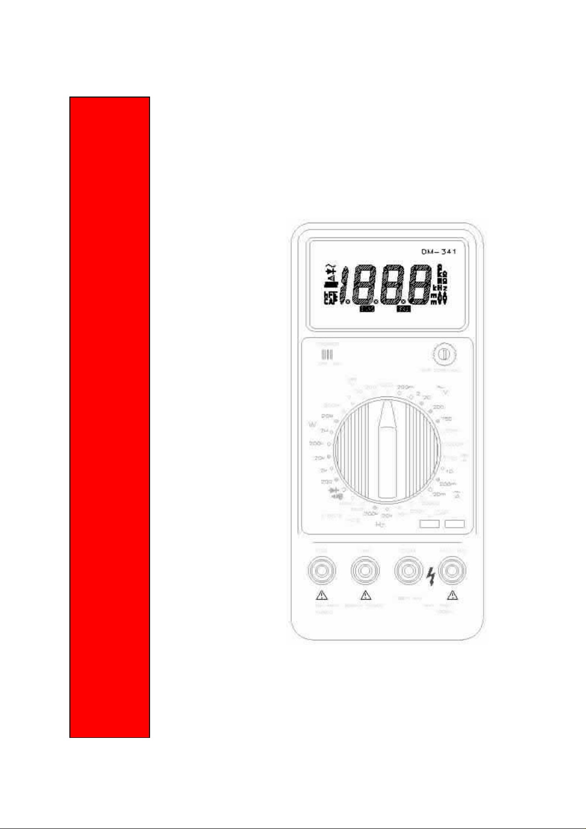
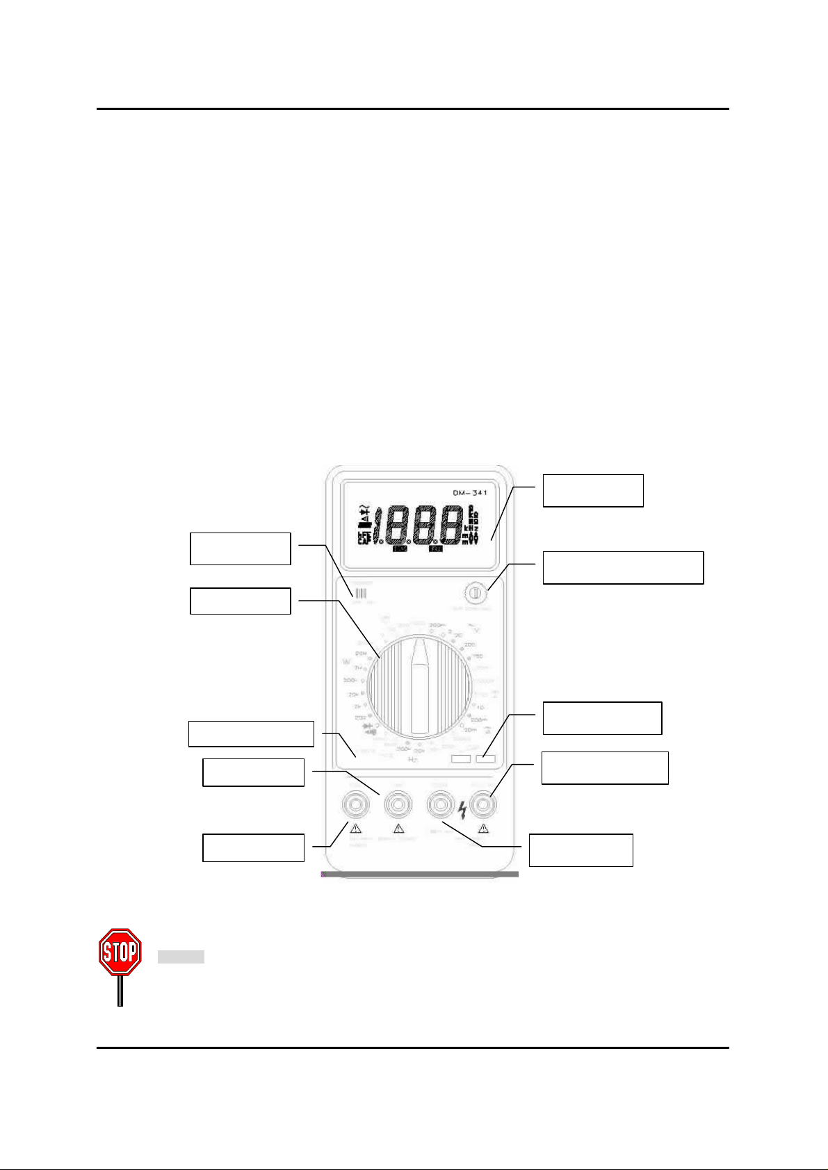
Rotary S/W
Transistor Socket
General Specifications of DM-341
Display: 4½ Digit Multimeter
Battery Life: Typical 200 hours
Operating Temperature: 0ºC ~ 40ºC (≤ 80% RH)
Storage temperature: -10ºC ~ 60ºC (≤ 70% RH)
Accuracy guaranteed temperature: 23ºC ± 5ºC (≤ 80% RH)
Maximum Reading Rate: 2 readings / second
Explanation of each part of DM-341
¨ç LCD Display
¨è Capacitor Zero Adjustment
Used for zero display adjustment in capacitor measure
mode.
¨é Power S/W
¨ê Rotary S/W
Used for selecting mode and range.
¨ë Capacitance Socket
Used for inserting capacitor to measure
¨ì Transistor Socket
Used for inserting transistor to measure
¨í Terminal Ω-V-Hz
Used for AC/DC voltage, Resistance and frequency
measure terminal
¨î Terminal COM
Used for common terminal
¨ï Terminal mA
Used for measuring DC/AC current below 200mA
current
¨ð Terminal 10A
Used for measuring DC/AC current below 10A
LCD Display
Power S/W
Terminal mA
Terminal 10A
Capacitor Zero Adjustment
Capacitor Socket
Terminal Ω-V-Hz
Terminal COM
Fig 1 - Front View of DM-341
Note
Adjustment and Test of DM-341 should be conducted under proper test environment.
Check operating temperature and relative humidity before adjustment and test.
Accuracy guaranteed temperature: 23ºC ± 5ºC (Below 80% RH)
Version 1.0 Page 3 of 11 LG Precision Co., Ltd.
Created : 1999/9/1
Modified :
Page 4

Adjustment and Test procedure Manual DM-341
l Test Equipment List
DMM Calibrator: 1set Decade Resistor: 1 set
Decade Capacitor: 1set Signal Generator: 1set
DC Power Supply (0 ~ 12V) or 9V Battery
Version 1.0 Page 4 of 11 LG Precision Co., Ltd.
Created : 1999/9/1
Modified :
Page 5

Adjustment and Test procedure Manual DM-341
l Calibration Procedure
1. Power On Test
Turn DM-341 on by using power S/W. and check LCD display is turned on.
2. LCD Display Test
Check LCD Display to each range by selecting range with Rotary S/W. Below chart shows correct display
Function LCD Display to each range
DC VOLTAGE
AC VOLTAGE
DC CURRENT
AC CURRENT
RESISTANCE
CAPACITANCE
hFE
FREQUENCY
DIODE & CONTINUITY 1 .
00.00 → .0000 → 0.000 → 00.00 → 000.0
00.00 → .0000 → 0.000 → 00.00 → 000.0
0.000 → 00.00 → 0.000
0.000 → 00.00 → 0.000
1 . → 1. →1 . →1 . →1. → 1 .
000.0 → 00.00 → 0.000
000.0 → 000.0
0.000 → 00.00
3. Low Battery Warning Display Test
Check a message, “BATT” on LCD display when Power supply or Battery Voltage goes below 6.4V.
4. Adjustment of DC voltage, AC voltage DC current, Capacitance ,Frequency and Diode.
Function
DC Voltage 189.98~190.02
AC Voltage 189.95~ 190.05
DC Current 9.995 ~ 10.005
Capacitance
Frequency
Adjustment
Specification
189.90 ~ 190.10
18.990 ~ 19.010
18.995 ~ 190.05
189.95 ~ 190.05
Procedure
1. Set Rotary S/W to DC Voltage 200mV range
2. Apply DC 190mV to Terminal COM and Terminal V of DM-341 with
a calibrator
3. Adjust VR1 to be displayed 190.00mV on LCD display
1. Set Rotary S/W to AC Voltage 200mV range
2. Apply AC 190mV/60Hz to Terminal COM and Terminal V with a calibrator
3. Adjust VR2 to be displayed 190.00mV on LCD display
1. Set Rotary S/W to DC Current 10A Mode
2. Apply DC 10A current to Terminal COM and Terminal 10Awith a calibrator
3. Adjust MN Wire(R30) to be displayed 10.000A on LCD display with a ripper
1. Set Rotary S/W to “CAP” 200nF Range
2. Set 00.00 display with ZERO ADJ.
3. Apply 190nF between CAP jack with a decade capacitor
4. Adjust VR4 to be displayed 190.00 on LCD display
1. Set Rotary S/W to “CAP” 20µF Range
2. Set 0.000 display with ZERO ADJ.
3. Apply 19µF between CAP jack with a Decade capacitor
4. Adjust VR3 to be displayed 19.000 on LCD display
1. Set Rotary S/W to “Hz” 20KHz Range
2. Apply 19KHz/RMS 100mV to Terminal V and Terminal COM.
3. Adjust VR7 to be displayed 19.000 kHz on LCD display
1. Set Rotary S/W to “Hz” 20KHz Range
2. Apply 190KHz/RMS 100mV to Terminal V and Terminal COM.
3. Adjust VR6 to be displayed 190.00 kHz on LCD display
Diode &
Continuity
99.95 ~ 100.05
1. Set Rotary S/W to Diode & Continuity mode
2. Apply 100 Ω to Terminal V and Terminal COM with decade resistor.
3. Adjust VR8 to be displayed 100.00Ω on LCD display
Version 1.0 Page 5 of 11 LG Precision Co., Ltd.
Created : 1999/9/1
Modified :
Page 6

Adjustment and Test procedure Manual DM-341
5.Test
5-1 No Input on DC Voltage Mode
n Specification : ±00.1mV
n Set Rotary S/W to DC Voltage 200mV range and check DM-341 to meet the above specification.
5-2 Short-circuit on DC Voltage Mode
n Specification : ±00.1 mV
n Set Rotary S/W to DC Voltage 200mV range and Short-circuit between terminal COM and terminal V
n Check DM-341 to meet the above specification.
5-3 DC Voltage Measurement Test
Set Rotary S/W to DC Voltage Mode and Apply below voltage to terminal COM and terminal V to each
range with a calibrator
Range
DC 200mV 190mV
DC 2V 1.9V
DC 20V 19V
DC 200V
DC 1000V
Customer
Specification
±(0.05% + 4dgt) ±(0.05% + 4dgt)
±(0.15% + 4dgt) ±(0.14% + 4dgt)
5-4 AC Voltage Measurement Test
Set Rotary S/W to AC Voltage Mode and Apply below voltage to terminal COM and terminal V to each
range with a calibrator. Check the measurement value to each frequency, 60Hz and 400Hz.
Range
AC 200mV
AC 2V
AC 20V
AC 200V
AC 750V
Customer
Specification
±(0.5%+10dgt) ±(0.45%+3dgt)
Factory
Specification
Factory
Specification
Test DC Voltage
190V
1000V
Test AC Voltage
190mV/60Hz
190mV/400Hz
1.9V/60Hz
1.9V/400Hz
19V/60Hz
19V/400Hz
190V/60Hz
190V/400Hz
750V/60Hz
750V/400Hz
5-5 DC Current Measurement Test
Set Rotary S/W to DC Current Mode and Apply below DC current to terminal COM and terminal mA to
each range with a calibrator. Check the measurement value to each range
Range
DC 20mΑ 19mΑ
DC 200mΑ
Customer
Specification
±(0.5%+1dgt) ±(0.4%+1dgt)
Factory
Specification
Test DC Current
190mΑ
Version 1.0 Page 6 of 11 LG Precision Co., Ltd.
Created : 1999/9/1
Modified :
Page 7

Adjustment and Test procedure Manual DM-341
Apply below DC current to terminal COM and terminal 10A with a calibrator.
Range
DC 10A
Customer
Specification
±(0.75%+3dgt) ±(0.65%+3dgt)
5-6 AC Current Measurement Test
Set Rotary S/W to AC Current 20mA Mode and Apply below AC current to terminal COM and terminal
mA to each range with a calibrator. Check the measurement value to each range
Range
AC 20mΑ
AC 200mΑ
Apply below AC current to terminal COM and terminal 10A with a calibrator.
Range
AC 10A
Customer
Specification
±(0.75%+10dgt) ±(0.65%+10dgt)
Customer
Specification
±(1.5%+10dgt) ±(1.4%+10dgt)
5-7 Resistance Measurement Test
Set Rotary S/W to Resistance Measure Mode and Apply below resistance value to terminal COM and
terminal V to each range with decade resistor. Check the measurement value to each range
Factory
Specification
Factory
Specification
Factory
Specification
Test DC Current
9A
Test AC Current
19mΑ/60Hz
19mΑ/400Hz
190mΑ/60Hz
190mΑ/400Hz
Test AC Current
9A/60Hz
9A/400Hz
Range
200Ω ±(2.0%+5dgt) ±(1.9%+5dgt) 190Ω
2kΩ 1.9kΩ
20kΩ 19kΩ
200kΩ
2MΩ 1.9MΩ
20MΩ
Customer
Specification
±(0.2%+2dgt) ±(0.2%+2dgt)
±(0.5%+2dgt) ±(0.4%+2dgt)
Factory
Specification
Test Resistance
value
190kΩ
10MΩ
5-8 Capacitor Measurement Test
Set Rotary S/W to “CAP” 200nF range and adjust ZERO ADJ to be displayed 00.0
And apply below capacitance value between CAP jack with a decade capacitor
Range
2000pF 1900pF
200nF
20µF
Customer
Specification
±(2.0%+6dgt) ±(1.9%+6dgt)
±(5.0%+4dgt) ±(4.9%+4dgt)
Factory
Specification
Test Capacitance
Value
190nF
19µF
Version 1.0 Page 7 of 11 LG Precision Co., Ltd.
Created : 1999/9/1
Modified :
Page 8

Adjustment and Test procedure Manual DM-341
5-9 Frequency Measurement Test
Set Rotary S/W to “HZ” mode and appl y below frequency value to terminal COM and terminal V with a
signal generator
Range
20KHz 19KHz/RMS 100mV
200KHz
Customer
Specification
±(2.0%+3dgt) ±(1.9%+3dgt)
5-10 Transistor hFE Measurement Test
Set Rotary S/W to “hFE” mode and insert transistor below to transistor socket
Range
NPN 3198 Y
PNP
Customer
Specification
5- 11Diode & Continuity Test
Set Rotary S/W to diode & continuity test mode and apply a diode to terminal COM and terminal V with
forward direction.
Range
Diode
Customer
Specification
Factory
Specification
Factory
Specification
120 ~ 240
Factory Specification
Forward Direction : 450.0 ≤
Reverse Direction : 1
Test Frequency
Value
190KHz/RMS 100mV
Test Transistor
1266Y
Set Rotary S/W to diode & continuity test mode and Short-circuit between terminal COM and terminal V.
Buzzer will sound when measurement is lower than 200Ω.
Range
Continuity
5-12 Short-circuit ohm Test
Set Rotary S/W to Resistance measure mode and short-circuit to terminal COM and terminal V
Range
200Ω Less than 0.4Ω
Customer
Specification
Customer
Specification
Factory Specification
Open Circuit : 1
Short Circuit : less than 000.4
Factory Specification
Version 1.0 Page 8 of 11 LG Precision Co., Ltd.
Created : 1999/9/1
Modified :
Page 9

Adjustment and Test procedure Manual DM-341
Appendix A) Bill of material
LGP P/N Category Specification PCB F/N Quantity
334-013-1 BUSHING INPUT CORE BLACK DMM 1
334-013-2 BUSHING INPUT CORE RED DMM 3
362-035 SPRING SHIELD SPRING DMM SP1 1
362-036 SPRING CAP CHK SPRING DMM 2
384-017-1 HOLDER BAT SNAP 9V UL 1
418-100 FILM VINYL PPI255 W=65.0 DMM M 1
513-564R7 PCB BARE B/D DM-341 PCB REV 7 1
521-108 SWITCH SW SLIDE KSA-1206 1
531-400 CONNECTOR HFE SOCKET ESQ-104-23-G-S 1
550-798-A WIRE HARNESS ASSY WH DMM341 1
563-063-2 FUSE 250V 0.25A 50F UL&EU F1 1
563-065 FUSE 250V 10A H216010 ULE14080 F2 1
563-068 FUSE 125V 1A 22NM MICRO 101L F3 1
564-015 FUSE HOLDER FUSE HOLDER FC51A(DMM) 4
571-316 VARIABLE RESISTOR VR TMC3K B20K (SMD) VR06 1
571-320 VARIABLE RESISTOR VR TMC3K 2K (SMD) VR02,VR04,VR08 3
571-321 VARIABLE RESISTOR VR TMC3K 5K (SMD) VR07 1
571-322 VARIABLE RESISTOR VR TM10K(PV) 8USB2K VR05 1
571-323 VARIABLE RESISTOR VR TMC3K 500 OHM(SMD) VR01,VR03 2
573-098 RESISTOR W.W 0.985 OHM 1W 0.25% R29 1
574-052-2 PTC PT05MP-L1K6001 R19 1
574-052-2 PTC PT05MP-L1K6001 R20 1
574-052-2 PTC PT05MP-L1K6001 R19A 1
574-055 SPARK GAP AG15PC 152FS-K2M DAIYOYDEN SG1 1
581-159 CAPACITOR CAP 0.047UF 63V M.P MKS C04 1
581-160 CAPACITOR ELEC 47UF 16V SRE-TYP C12 C13 C26 3
581-162 CAPACITOR ELEC 1UF 50V SRE-TYPE C16 C17 C18 C32 C33 5
581-176 CAPACITOR ELEC 10UF 16V SRE-TYPE C07 C10 2
581-195 CAPACITOR MP 0.1UF 63V J MMY168 C03 C05 C15 C27 4
581-204 CAPACITOR MP 0.01UF 63V J MMY168 C28 1
581-221 CAPACITOR ELEC 0.47UF 50V SRE-TYPE C19 1
585-154-1 DIODE RL105 D01 D02 D06 D07 4
585-248 DIODE KDS226 (SMD) KEC D03 D08 2
585-261 DIODE KDS187 (SMD) D04 D05 2
586-003
591-500 IC CADDOCK 1776-C611 R16 1
591-647-2 IC MC74HC00AD (SMD) MOTOROLA U02 1
591-650 IC NJM062M-T1 OP-AMP NJRC U03 1
591-651-1 IC TIMER TS555ID THOMSON U4 U5 U6 3
591-653-1 IC LM393D (SMD) MOTOROLA U07 1
591-659 IC TC7129CKW A-D CON TELEDYN U01 1
611-665 TRANSISTOR KRC110S (SMD) Q01 1
611-671 TRANSISTOR SS8050 SAMSUNG Q02 Q3 2
637-013 BUZZER BUZZ SBT-11P B01 1
648-075 CRISTAL F=120KHZ TF TYPE Y1 1
873-028R MN WIRE MN WIRE CM2 10MOHM R30 1
873-027 Mn WIRE CM2 DIA 1.6MM Mn WIRE CM2 DIA1.6MM 1
CK1HI100D CAPACITOR CER 10PF 50V D (2012) C02 1
CK1HI101J CAPACITOR CER 100PF 50V J (2012) C22 1
CK1HI102K CAPACITOR CER 1000PF 50V K (2012) C21 1
VOLTAGE REFERENCE
IC
LM385BLP-1-2 Z1 1
Version 1.0 Page 9 of 11 LG Precision Co., Ltd.
Created : 1999/9/1
Modified :
Page 10

Adjustment and Test procedure Manual DM-341
LGP P/N Category Specification PCB F/N Quantity
CK1HI104M CAPACITOR CER 0.1UF 50V M (2012) C06 C09 C25 3
CK1HI150J CAPACITOR CER 15PF 50V J (2012) C29 1
CK1HI220J CAPACITOR CER 22PF 50V J (2012) C1 1
CK1HI221J CAPACITOR CER 220PF 50V J (2012) C11 1
CK1HI224M CAPACITOR CER 0.22UF 50V M (3216) C31 1
CK1HI272K CAPACITOR CER 2700PF 50V K (2012)X7R C30 1
CK1HI680J CAPACITOR CER 68PF 50V J (2012) C24 1
CK2HI102K CAPACITOR CER 1000PF 500V K (1808) C20 1
RD0BP105J RESISTOR C.F 1 M OHM 1/4W 5% R31 1
RG0CP226J RESISTOR M.G 22 MOHM 1/2W 5% R32 1
RM2P1303J RESISTER M.F 130KOHM 2W 5% R40 1
RMAH1000J RESISTOR M.F 100 -OHM 1/8W 5% (3216) R13 R21 2
RMAH1002J RESISTOR M.F 10 KOHM 1/8W 5% (3216) R33 R34 2
RMAH1003J RESISTOR M.F 100 KOHM 1/8W 5% (3216) R23 1
RMAH1004F RESISTOR M.F 1 MOHM 1/8W 1% (3216) R57 1
RMAH1004F RESISTOR M.F 1 MOHM 1/8W 1% (3216) R11,R12 2
RMAH1004J RESISTOR M.F 1 MOHM 1/8W 5% (3216) R03,R04 2
RMAH1004J RESISTOR M.F 1 MOHM 1/8W 5% (3216) R24 R25 R27 R53 4
RMAH1004J RESISTOR M.F 1 MOHM 1/8W 5% (3216) R54 R64 R65 3
RMAH10R0J RESISTOR M.F 10 -OHM 1/8W 5% (3216) R47 1
RMAH1102F RESISTOR M.F 11 KOHM 1/8W 1% (3216) R39 1
RMAH1103F RESISTOR M.F 110 KOHM 1/8W 1% (3216) R48 1
RMAH1301F RESISTOR M.F 1.3 KOHM 1/8W 1% (3216) R55 1
RMAH1403F RESISTOR M.F 140 KOHM 1/8W 1% (3216) R49 1
RMAH1502F RESISTOR M.F 15 KOHM 1/8W 1% (3216) R56 1
RMAH1503J RESISTOR M.F 150 KOHM 1/8W 5% (3216) R02 1
RMAH1603F RESISTOR M.F 160 KOHM 1/8W 1% (3216) R51 1
RMAH1802J RESISTOR M.F 18 KOHM 1/8W 5% (3216) R41 R50 2
RMAH2203F RESISTOR M.F 220 KOHM 1/8W 1% (3216) R46 1
RMAH2400J RESISTOR M.F 240 -OHM 1/8W 5% (3216) R67 1
RMAH2401F RESISTOR M.F 2.4 KOHM 1/8W 1% (3216) R38 1
RMAH2702F RESISTOR M.F 27 KOHM 1/8W 1% (3216) R59 1
RMAH2702F RESISTOR M.F 27 KOHM 1/8W 1% (3216) R45 1
RMAH2702J RESISTOR M.F 27 KOHM 1/8W 5% (3216) R42,44 2
RMAH3301F RESISTOR M.F 3.3 KOHM 1/8W 1% (3216) R36 1
RMAH3303F RESISTOR M.F 330 KOHM 1/8W 1% (3216) R01,R52,R61,R62 4
RMAH4701F RESISTOR M.F 4.7 KOHM 1/8W 1% (3216) R37 R60 2
RMAH4702J RESISTOR M.F 47 KOHM 1/8W 5% (3216) R5,R10 2
RMAH4703F RESISTOR M.F 470 KOHM 1/8W 1% (3216) R58 1
RMAH4703J RESISTOR M.F 470 KOHM 1/8W 5% (3216) R35 R63 2
RMAH5100J RESISTOR M.F 510 -OHM 1/8W 5% (3216) R15 1
RMAH51R0J RESISTOR M.F 51 -OHM 1/8W 5% (3216) R66 1
RMAH7503J RESISTOR M.F 750 KOHM 1/8W 5% (3216) R06 R07 R08 R09 4
RMAH8200J RESISTOR M.F 820 -OHM 1/8W 5% (3216) R14 1
RMAH8201F RESISTOR M.F 8.2 KOHM 1/8W 1% (3216) R26 1
RMAH9103J RESISTOR M.F 910 KOHM 1/8W 5% (3216) R22 1
RMBP1000B RESISTOR M.F 100 -OHM 1/4W .1% R17 1
RMBP1001B RESISTOR M.F 1 KOHM 1/4W .1% R18 1
RMBP2701F RESISTOR M.F 2.7 KOHM 1/4W 1% R68 1
RMBP9R00C RESISTOR M.F 9 -OHM 1/4W .25% R28 1
Version 1.0 Page 10 of 11 LG Precision Co., Ltd.
Created : 1999/9/1
Modified :
Page 11

Adjustment and Test procedure Manual DM-341
Appendix B) Schematic Diagram of DM-341
Version 1.0 Page 11 of 11 LG Precision Co., Ltd.
Created : 1999/9/1
Modified :
 Loading...