


OWNER'S MANUAL
DRYER
Read this owner's manual thoroughly before operating the
appliance and keep it handy for reference at all times.
ENGLISH
DLHC1455*
MFL71424358
Rev.05_011321
www.lg.com
Copyright © 2020-2021 LG Electronics Inc. All Rights Reserved.

2
TABLE OF CONTENTS
3 IMPORTANT SAFETY
INSTRUCTIONS
3 READ ALL INSTRUCTIONS BEFORE USE
3 WARNING STATEMENTS
6 CAUTION STATEMENTS
7 PRODUCT OVERVIEW
7 Product Features
9 INSTALLATION
9 Before Installing
10 Choosing the Proper Location
14 Leveling the Appliance
14 Reversing the Door
16 Stacking the Appliance
17 Connecting Electric Dryers
21 Special Electrical Requirements
21 Final Installation Check
22 OPERATION
22 Before Use
23 Loading the Dryer
24 Control Panel
26 Drying Cycles
30 Options and Extra Functions
33 SMART FUNCTIONS
33 LG ThinQ Application
35 Smart Diagnosis
TM
Function
37 MAINTENANCE
37 Regular Cleaning
39 Periodic Cleaning
41 Care in Cold Climates
43 TROUBLESHOOTING
43 FAQs
44 Before Calling for Service
48 WARRANTY
48 USA
IMPORTANT SAFETY INSTRUCTIONS
WARNING
3IMPORTANT SAFETY INSTRUCTIONS
READ ALL INSTRUCTIONS BEFORE USE
Safety Messages
Your safety and the safety of others are very important.
We have provided many important safety messages in this manual and on your appliance. Always read and
follow all safety messages.
This is the safety alert symbol.
This symbol alerts you to potential hazards that can kill or injure you and others. All safety messages
will follow the safety alert symbol and either the word WARNING or CAUTION.
WARNING
You may be killed or seriously injured if you do not follow instructions.
CAUTION
You may be injured or cause damage to the product if you do not follow instructions.
All safety messages will tell you what the potential hazard is, tell you how to reduce the chance of injury, and
tell you what may happen if the instructions are not followed.
WARNING STATEMENTS
ENGLISH
• To reduce the risk of explosion, fire, death, electric shock, scalding or injury to persons when using this
product, follow basic precautions, including the following:
Installation
• Before use, the appliance must be properly installed as described in this manual.
• Connect to a properly rated, protected, and sized power circuit to avoid electrical overload.
• To reduce the risk of severe injury or death, follow all installation instructions.
• The appliance must be installed and electrically grounded by qualified service personnel in accordance
with local codes.
• Disconnect the power cord, house fuse or circuit breaker before installing or servicing the appliance.
• When moving or installing the appliance in a different location, call qualified service personnel for
installation and service.
• Keep packing materials out of the reach of children. Packaging material can be dangerous for
children.There is a risk of suffocation.
• Moving or installation of the appliance requires two or more people.
• This appliance is not designed for maritime use or for mobile installations such as in RVs, trailers, or
aircraft.
• This appliance must be positioned near to an electrical power supply.
• Do not, under any circumstances, cut or remove the third (ground) prong from the power cord.
• When installing or moving the appliance, be careful not to pinch, crush, or damage the power cord.
• Do not install the appliance in humid spaces.

4 IMPORTANT SAFETY INSTRUCTIONS
• Destroy the carton, plastic bag, and other packing materials after the appliance is unpacked. Children
might use them for play. Cartons covered with rugs, bedspreads, or plastic sheets can become airtight
chambers.
• Adhere to all industry recommended safety procedures including the use of long-sleeved gloves and
safety glasses.
• Place the appliance at least 18 inches above the floor for a garage installation.
• Do not install near another heat source such as a stove, oven or heater.
• Keep area around the exhaust opening and adjacent surrounding areas free from the accumulation of
lint, dust, and dirt.
• The appliance must not be supplied through an external switching device, such as a timer, or connected
to a circuit that is regularly switched on and off by a utility.
• Certain internal parts are intentionally not grounded and may present a risk of electric shock only during
servicing. Service personnel – Do not contact the following parts while the appliance is energized: Motor,
Control Board, Noise Filter.
Operation
• Never attempt to operate this appliance if it is damaged, malfunctioning, partially disassembled, or has
missing or broken parts, including a damaged cord or plug.
• Repair or immediately replace all power cords that have become frayed or otherwise damaged. Do not
use a cord that shows cracks or abrasion damage along its length or at either end.
• If you detect a strange sound, a chemical or burning smell, or smoke coming from the appliance, unplug
it immediately, and contact an LG Electronics customer information center.
• Never unplug the appliance by pulling on the power cord. Always grip the plug firmly and pull straight
out from the outlet.
• Do not use an extension cord or adapter with this appliance.
• Do not grasp the power cord or touch the appliance controls with wet hands.
• Do not modify or extend the power cord.
• If the appliance has been submerged, contact an LG Electronics customer information center for
instructions before resuming use.
• Do not store or use gasoline or other flammable vapors and liquids in the vicinity of this or any other
appliance.
• Keep the area underneath and around your appliances free of combustible materials (lint, paper, rags,
etc.), gasoline, chemicals and other flammable vapors and liquids.
• This appliance is not intended for use by persons (including children) with reduced physical, sensory or
mental capabilities, or lack of experience and knowledge, unless they have been given supervision or
instruction concerning the use of the appliance by a person responsible for their safety.
• Use this appliance only for its intended purpose.
• Do not abuse, sit on, or stand on the door of the appliance.
• Do not allow children to play on, in or with the appliance. Close supervision of children is necessary when
the appliance is used near children.
• Do not tamper with controls.
• Do not put oily or greasy clothing, candles or flammable materials on top of the appliance.
• Do not reach into the appliance if the drum is moving.
• Do not dry articles that have been previously cleaned in, washed in, soaked in, soiled with or spotted
with gasoline, dry cleaning solvents, vegetable oil, cooking oil or other flammable or explosive
substances, as they give off vapors that could ignite or explode.
• Do not use heat to dry articles containing foam rubber or similarly textured rubber-like materials.
• Do not store plastic, paper, or clothing that may burn or melt on top of the dryer during operation.

• Always check the inside of the appliance for foreign objects.
• Do not place items exposed to cooking oils in your dryer. Items contaminated with cooking oils may
contribute to a chemical reaction that could cause a load to catch fire. To reduce the risk of fire due to
contaminated loads, the final part of a tumble dryer cycle occurs without heat (cool down period). Avoid
stopping a tumble dryer before the end of the drying cycle unless all items are quickly removed and
spread out so that the heat is dissipated.
• Do not let children or pets climb inside the dryer drum.
• Do not put living animals such as pets inside the appliance.
• Do not put any part of your body, such as your hands or feet, or metal objects under the appliance.
• Do not let your hand get pinched when opening or closing the dryer door.
Maintenance
• Do not repair or replace any part of the appliance. All repairs and servicing must be performed by
qualified service personnel unless specifically recommended in this Owner’s Manual. Use only
authorized factory parts
• Do not disassemble or repair the appliance by yourself.
• Remove any dust or foreign matter from the power plug pins.
• Disconnect this appliance from the power supply before cleaning and attempting any user maintenance.
Turning the controls to the OFF position does not disconnect this appliance from the power supply.
• Remove the door before the appliance is removed from service or discarded to avoid the danger of
children or small animals getting trapped inside.
• Unplug the appliance before cleaning to avoid the risk of electric shock.
• Certain internal parts are intentionally not grounded and may present a risk of electric shock only during
servicing. Service personnel – Do not contact the following parts while the appliance is energized: Motor,
Control Board, Noise Filter.
5IMPORTANT SAFETY INSTRUCTIONS
ENGLISH
Grounding Instructions
• Improper connection of the equipment-grounding conductor can result in a risk of electric shock. Check
with a qualified electrician or service personnel if you are in doubt whether the appliance is properly
grounded. Do not modify the plug provided with the appliance; if it will not fit the outlet, have a proper
outlet installed by a qualified electrician.
• The appliance must be grounded. In the event of a malfunction or breakdown, grounding will reduce the
risk of electric shock by providing a path of least resistance for electric current. The appliance is
equipped with a cord having an equipment-grounding conductor and a grounding plug. The plug must
be plugged into an appropriate outlet that is installed and grounded in accordance with all local codes
and ordinances.
• The appliance must be plugged into a properly grounded outlet. Electrical shock may result if the
appliance is not properly grounded. Have the wall outlet and circuit checked by a qualified electrician to
make sure the outlet is properly grounded. Failure to follow these instructions may create an electric
shock hazard and/or a fire hazard.

6 IMPORTANT SAFETY INSTRUCTIONS
CAUTION
CAUTION STATEMENTS
• To reduce the risk of minor or moderate injury to persons, malfunction, or damage to the product or
property when using this product, follow basic precautions, including the following:
Installation
• Install the appliance on a firm and level floor.
• Store and install the appliance where it will not be exposed to temperatures below freezing or exposed
to outdoor weather conditions.
Operation
• Clean the lint filter before or after each load.
• Do not use fabric softeners or products to eliminate static unless recommended by the manufacturer of
the fabric softener or product.
• If the drain hose is frozen in winter, thaw it out before use.
SAVE THESE INSTRUCTIONS
PRODUCT OVERVIEW
7PRODUCT OVERVIEW
Product Features
The images in this guide may be different from the actual components and accessories, which are subject
to change by the manufacturer without prior notice for product improvement purposes.
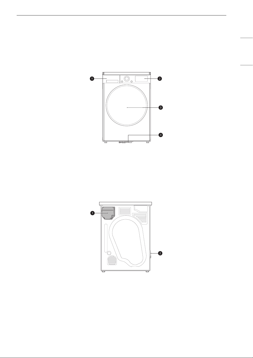
Front View
a Water Container
b Control Panel
c Door
d Drain Tube
ENGLISH
Rear View
a Terminal Block Access Panel
b External drainage of condensed water
8 PRODUCT OVERVIEW
NOTE
NOTE
Product Specifications
The appearance and specifications listed in this manual may vary due to constant product improvements.
Electrical requirements: Please refer to the rating label for detailed information.
Model DLHC1455*
Description Heat Pump Electric Dryer
Dimensions (Width × Depth × Height) 23 5/8'' x 27 1/4'' x 33 1/2'', 45 1/4'' (Depth with door
open)
60 cm x 69 cm x 85 cm, 115 cm (Depth with door
open)
Net Weight 125.7 lb (58 kg)
Drying Capacity Normal Cycle IEC 4.2 cu.ft (19.8 lb/9 kg)
• Model numbers can be found on the cabinet inside the door.
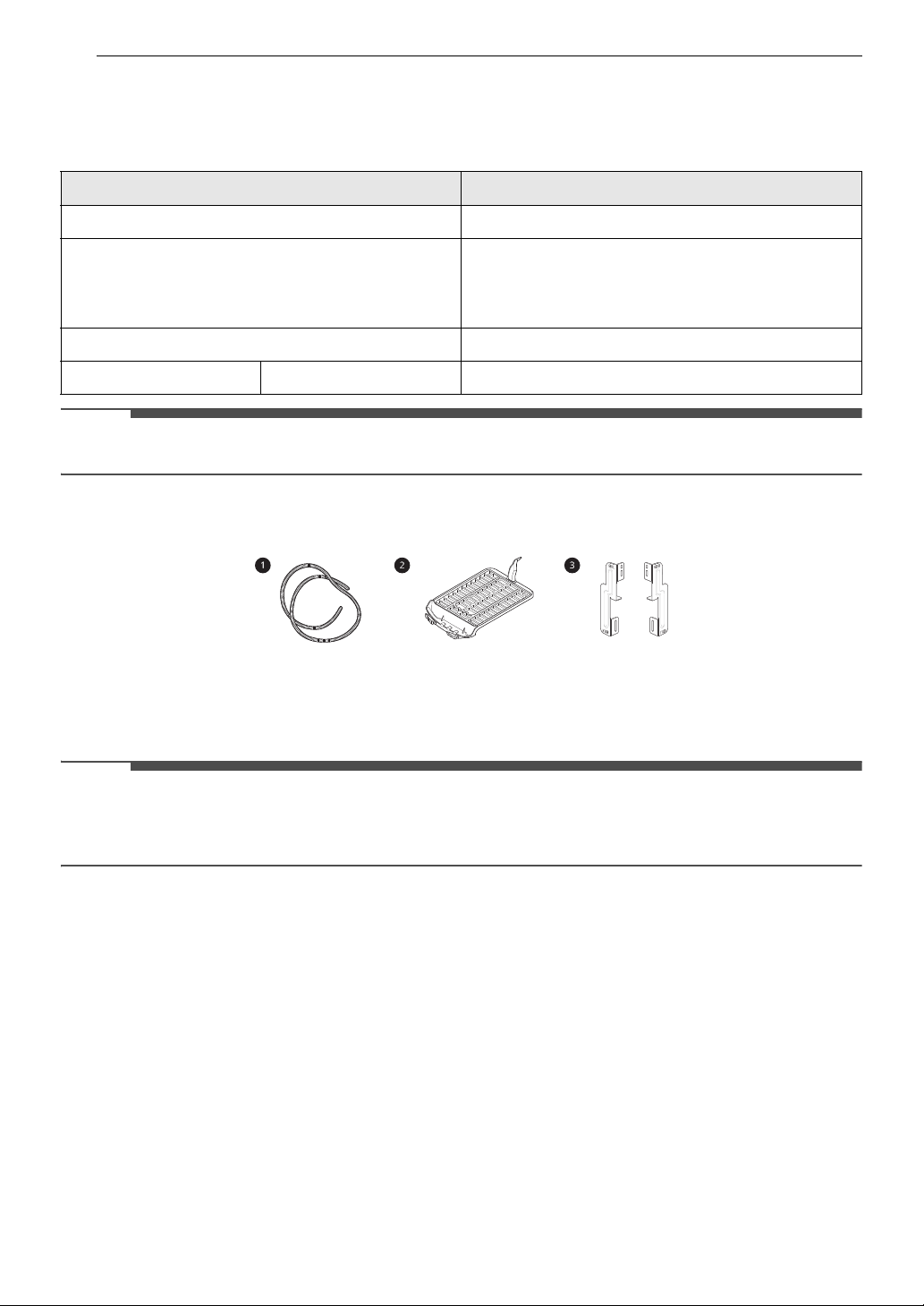
Accessories
a Drain hose
b Drying rack (sold separately)
c Stacking kit
• For your safety and extended product life, use only authorized components. The manufacturer is not
responsible for product malfunction or accidents caused by the use of unauthorized components or
parts.
INSTALLATION
9INSTALLATION
Before Installing
Installation Overview
Please read the following installation instructions first after purchasing this dryer or transporting it to
another location.
a Choose the proper location.
ENGLISH
b Level the appliance.
c Connect the heat pump electric dryer.
d Plug in the power cord.
e Final Installation Check
10 INSTALLATION
WARNING
WARNING
NOTE
NOTE
Choosing the Proper
Location
• Read all installation instructions completely
before installing and operating the appliance. It
is important that you review this entire manual
before installing and using the appliance.
Detailed instructions concerning electrical
connections and additional requirements are
provided on the following pages.
Electricity
Use an individual, grounded electrical outlet
located within 2 ft. (61 cm) of either side of the
appliance.
• Do not install or store the appliance in an area
where it will be exposed to water and/or
weather.
Ambient Temperature
Install the appliance in an area where the
temperature is over 45 ℉ (7 ℃).
If the temperature around the appliance is too low,
the appliance might not shut off at the end of an
automatic cycle. This can result in longer drying
times.
• Check code requirements that limit, or do not
permit, installation of the dryer in garages,
mobile homes or sleeping quarters. Contact
your local building inspector.
Flooring
To avoid noise and vibration, the appliance must
be installed and leveled on a solidly constructed
floor with a maximum slope of 1 inch (2.5 cm). If
required, adjust the leveling legs to compensate
for the unevenness of the floor.
• A sturdy floor is needed to support the total
appliance weight when loaded. The combined
weight of a companion appliance should also be
considered.
• Clothes may not tumble properly, and automatic
sensor cycles may not operate correctly if the
appliance is not level.
• Far garage installation, you will need to place the
appliance at least 18 inches (45.7 cm) above the
floor. The standard pedestal height is 15 inches
(38 cm). You will need 18 inches (45.7 cm) from
the garage floor to the bottom of the appliance.
Dimensions and Clearances
The following clearances are recommended for the appliance.
• Additional clearances should be considered for ease of installation and servicing.
• Additional clearances should be considered on all sides of the dryer to reduce noise transfer.
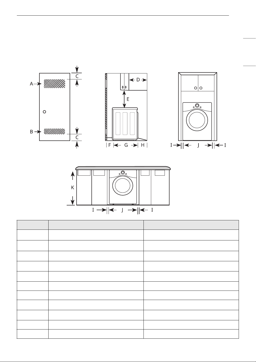
Installation spacing for Recessed Area or Closet Installation
11INSTALLATION
ENGLISH
- Description Dimension/Clearance
A Upper Ventilation Opening
B Lower Ventilation Opening
C Distance to Ventilation Opening
D Overhead Cabinet Depth
E Distance to the Overhead Cabinet/Shelf
F Front Clearance 1″ (25 mm)
G Depth 27 1/4″ (690 mm)
HBack Clearance
I Side Clearance
J Width 23 5/8″ (600 mm)
K Height of Cabinet Opening 33 1/2″ (850 mm)
2 48 sq. in. (310 cm
2 24 sq. in. (155 cm
2 3″ (76 mm)
1 14″ (356 mm)
2 18″ (457 mm)
2 5″ (127 mm)
2 1″ (25 mm)
2
)
2
)
12 INSTALLATION
NOTE
Closet Ventilation Requirements
Closets with doors must have both an upper and lower vent to prevent heat and moisture buildup in the
closet. One upper vent opening with a minimum opening of 48 sq. in. (310 cm
than 6 feet above the floor. One lower vent opening with a minimum opening of 24 sq. in. (155 cm
be installed no more than one foot above the floor. Install vent grills in the door or cut down the door at
the top and bottom to form openings. Louvered doors with equivalent ventilation openings are also
acceptable.
• There should be at least a little space around the dryer (or any other appliance) to eliminate the transfer
of vibration from one appliance to another. If there is enough vibration, it could cause appliances to
make noise or come into contact, causing paint damage and further increasing noise.
• No other fuel-burning appliance can be installed in the same closet as a dryer.
2
) must be installed no lower
2
) must
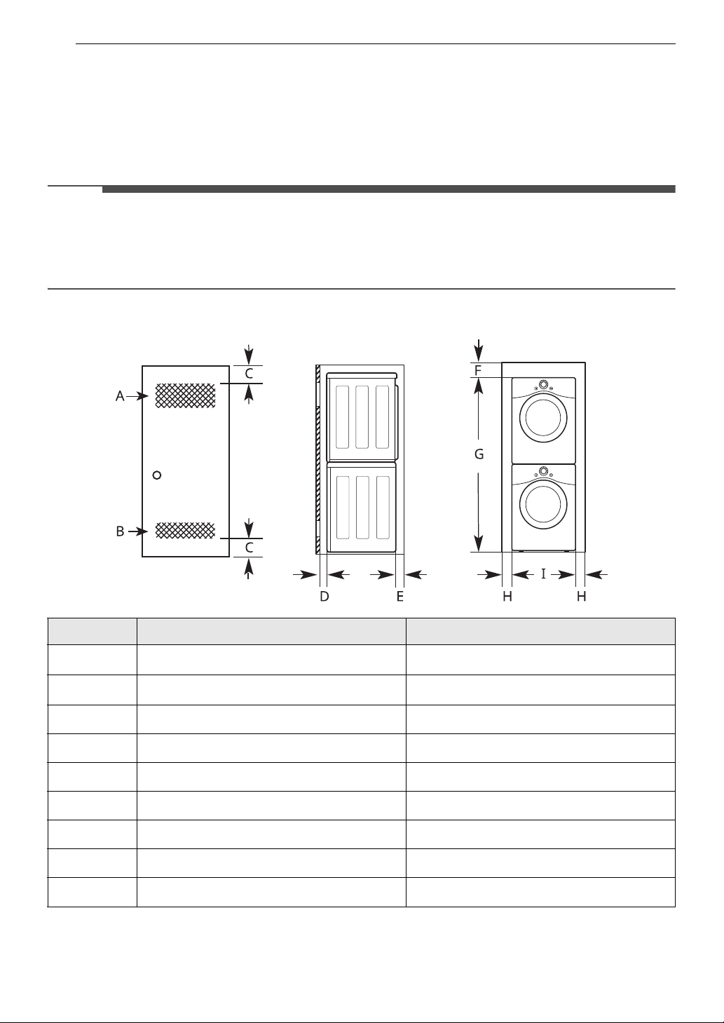
Installation Spacing for Recessed Area or Closet, with Stacked Washer and Dryer
- Description Dimension/Clearance
A Upper Ventilation Opening
B Lower Ventilation Opening
C Distance to Ventilation Opening
D Front Clearance
EBack Clearance
F Top Clearance to the Ceiling
G
H Side Clearance
I
Height to the Top of Stacked Appliances
†
Width
† Differs depending on the washer dimensions.
2 48 sq. in. (310 cm
2 24 sq. in. (155 cm
2
)
2
)
2 3″ (76 mm)
2 1″ (25 mm)
2 5 1/2″ (140 mm)
2 6″ (152 mm)
†
67″ (1700 mm)
2 1″ (25 mm)
23 5/8″ (600 mm)
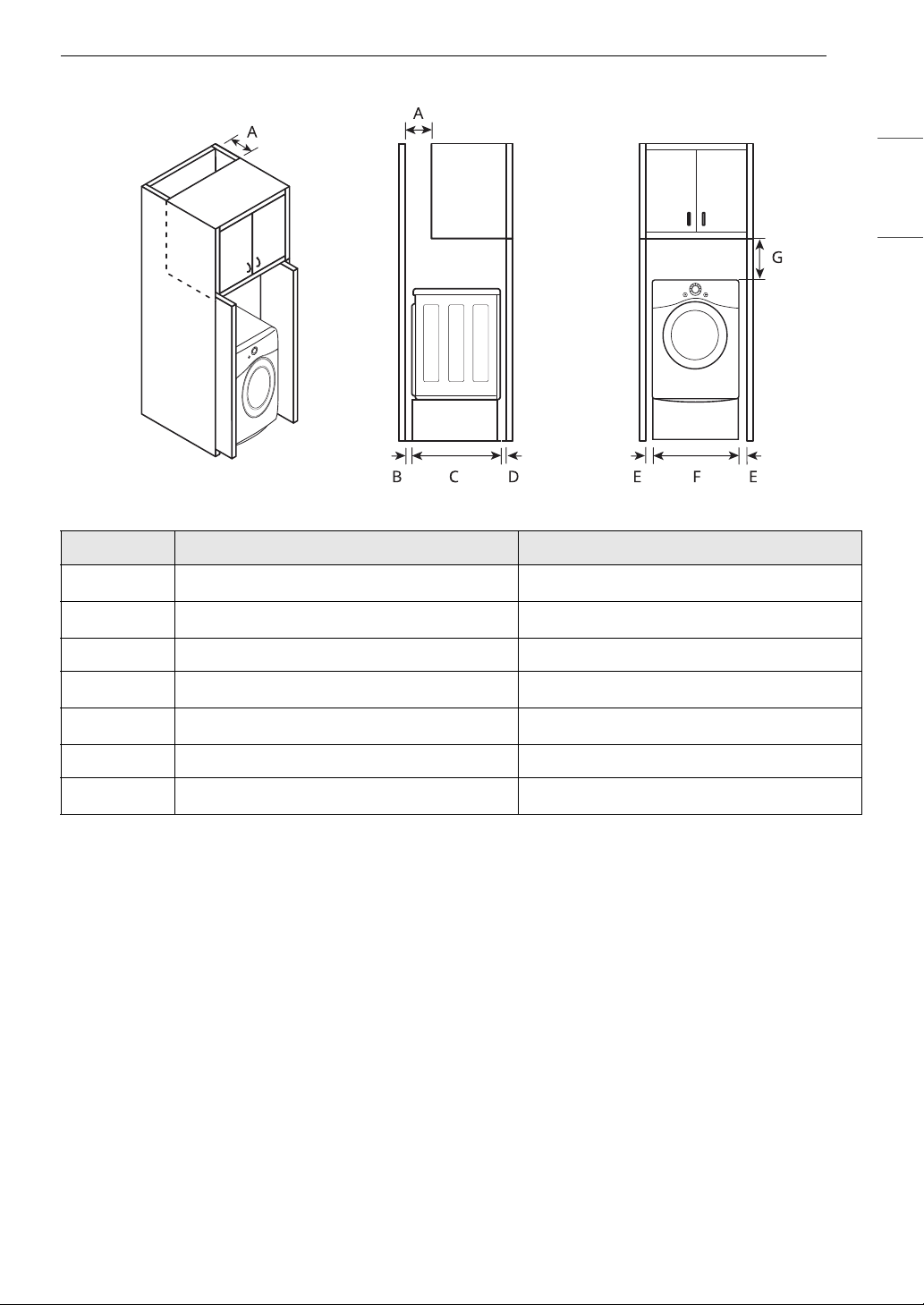
Installation Spacing for Cabinet
For cabinet installation with a door, minimum ventilation openings in the top of the cabinet are required.
- Description Dimension/Clearance
13INSTALLATION
ENGLISH
A Depth of Ventilation Opening
BBack Clearance
C Depth 27 1/4″ (690 mm)
D Front Clearance
E Side Clearance
F Width 23 5/8″ (600 mm)
G Clearance to Top of Cabinet
2 7″ (178 mm)
2 5″ (127 mm)
2 1″ (25mm)
2 1″ (25 mm)
2 9″ (229 mm)
14 INSTALLATION
WARNING
NOTE
NOTE
WARNING
WARNING
Leveling the Appliance
• Use long-sleeved gloves and safety glasses.
• The appliance is heavy. Two or more people are
required when installing the appliance.
Checking the Level
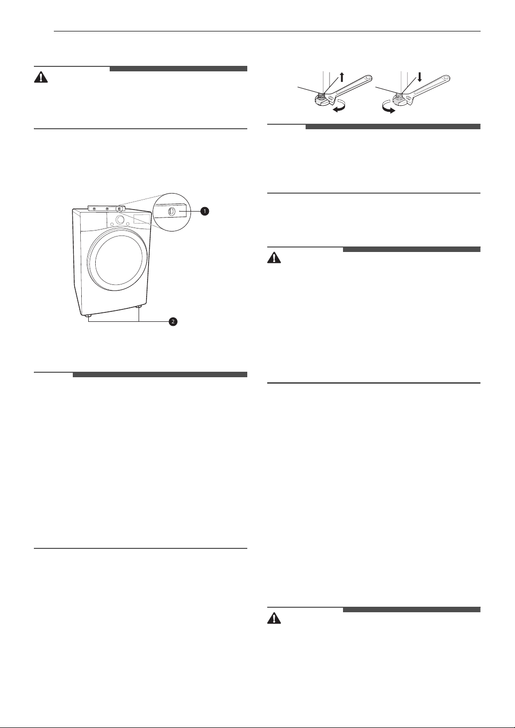
Position the appliance in the final location and
place a level across the top of the appliance.
a Level
b Leveling Feet
and front to back. Make sure that all four leveling
feet are in firm contact with the floor.
• If you are installing the appliance on the optional
pedestal, you must use the leveling feet on the
pedestal to level the appliance. The appliance
leveling feet should be fully retracted.
Reversing the Door
• Support the door with a stool or box that fits
under the door, or have an assistant support the
weight of the door.
• Avoid dropping the door.
• Unplug the appliance or turn off power at the
main circuit breaker before beginning door
reversal.
• Always reverse the door BEFORE stacking the
appliance on top of the washer.
• All four leveling feet must rest solidly on the
floor. Gently push on the top corners of the
appliance to make sure that the appliance does
not rock from corner to corner.
• Adjust the leveling feet only as far as necessary
to level the appliance. Extending the leveling feet
more than necessary may cause the appliance to
vibrate.
• To ensure that the appliance provides optimal
drying performance, it must be level. To
minimize vibration, noise, and unwanted
movement, the floor must be a perfectly level,
solid surface.
Adjusting the Leveling Feet
Use an adjustable wrench to turn the leveling feet.
Unscrew the legs to raise the appliance or screw in
the legs to lower it. Raise or lower with the leveling
feet until the appliance is level from side to side
Tools Required
• Phillips screwdriver
• Large flat blade screwdriver (recommended for
hinge screws if they are tight or your Phillips
screwdriver is worn)
• Small flat blade screwdriver (for lifting out parts)
Door Reversal Instructions
The instructions here are for changing the door
swing from a right to a left side hinge. If the door
has been reversed, and it is necessary to change it
back, use care when following these instructions.
Some of the illustrations and the left/right
references will be reversed, and you will need to
read the instructions carefully.
• Do not reverse the door while the appliance is
stacked on a washing machine.
• Before removing the hinge screws, have an
assistant support the weight of the door. The
door could fall on the floor due to the weight of
the door.
• For safety reasons, two or more people need to
NOTE
WARNING
c
d
cd
work together to reverse the door.
• The appearance of the screws varies and the
screws must be inserted differently depending
on the position. Make sure that you've selected
the correct screw before tightening.
15INSTALLATION
ENGLISH
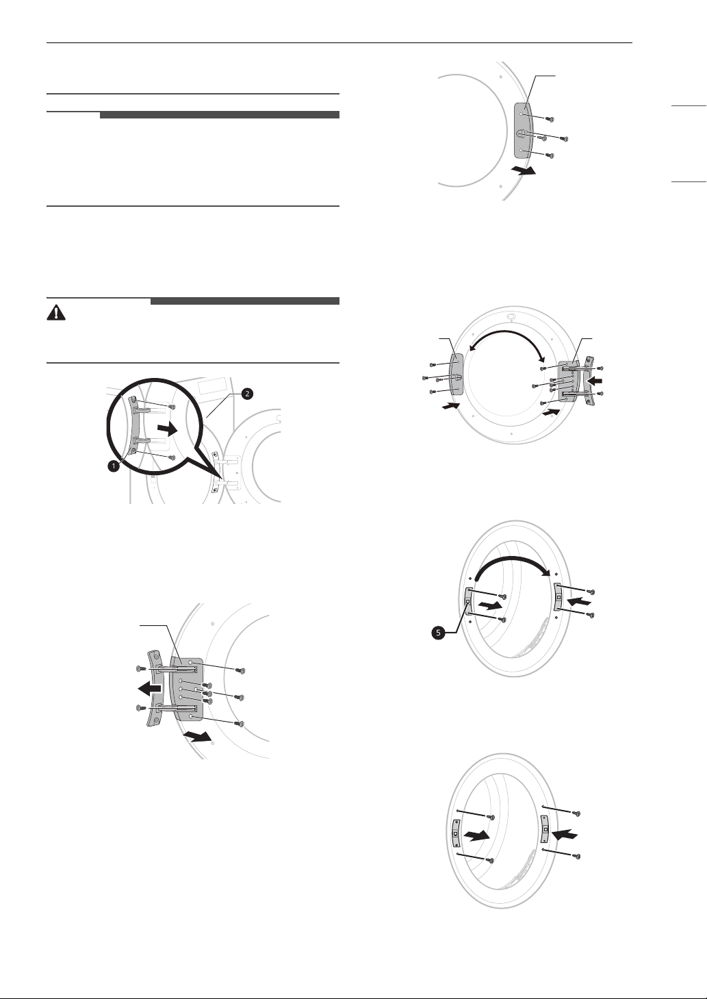
1 Open the door and remove 2 screws on the
door hinge
cabinet b and place it inside facing up on a
non-scratching surface.
• Be sure to support the weight of the door before
removing the hinge screws.
a. Remove the door from the
2 Remove 8 screws and remove the hinge
assembly c from the door.
• There are 6 screws on the front and 2
screws on the side.
4 Swap the position of the hinge assembly c
and the door latch assembly
reassemble. Refer to steps 2 and 3 for the
location and number of screws when
reassembling.
d and
5 On the appliance cabint, unscrew 2 screws
and remove the door catch
on the opposite side of the door.
e. Reassemble it
3 Remove the 3 screws from the door latch
assembly
door and the hinge assembly. Remove the
screw in the door latch.
d which is mounted between the
6 Remove the 2 decorative screws from the
appliance cabinet and insert them on the
opposite side.
16 INSTALLATION
WARNING
7 Reassemble the door on the cabinet using the
screws removed in step 1. Make sure that the
door opens, closes and latches properly.
Stacking the Appliance
Stacking Kit Overview
In order to stack the appliance, an LG stacking kit
is required.
Stacking Kit Installation
• The weight of the appliance and the height of
installation make this stacking procedure too
risky for one person. Two or more people are
required when installing the stacking kit.
• Place the washer on a solid, stable, level floor
capable of supporting the weight of both
appliances.
• Do not stack the washer on top of the dryer.
• If appliances are already installed, disconnect
them from all power, water, and drainage
connections.
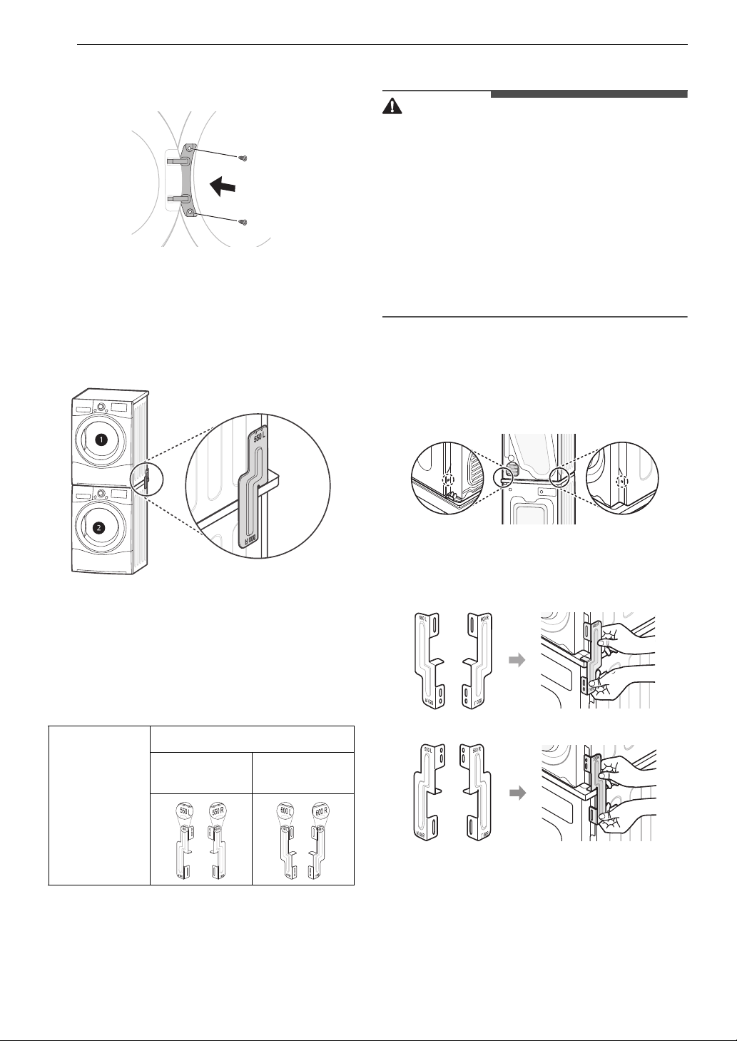
1 Place the appliance on the top of an LG front
load washing machine.
2 Remove the 1 screw from the bottom of the
rear cover on each side.
a Dryer
b LG Front Load Washing Machine
The appliance may only be stacked on top of an LG
front load washing machine. Do not attempt to
stack the appliance on any other washing
machine, as it could result in damage, injury or
property damage.
Shape and
assembly
direction
Washing Machine Top plate size
21 7/8 inch
(550 mm)
23 5/8 inch
(600 mm)
Tools Required
• Phillips screwdriver
3 Align the hole in the bracket with the hole in
the rear cover of the appliances.
• If using the 23 5/8″ (600 mm) top plate:
• If using the 21 7/8″ (550 mm) top plate:
4 Use the 2 screws removed earlier to hold the
stacking brackets in place on each side.
5 Use the four 0.6″ (16 mm) screws provided in
the accessory box to secure the brackets in
place.
17INSTALLATION
CAUTION
b
a
a
c
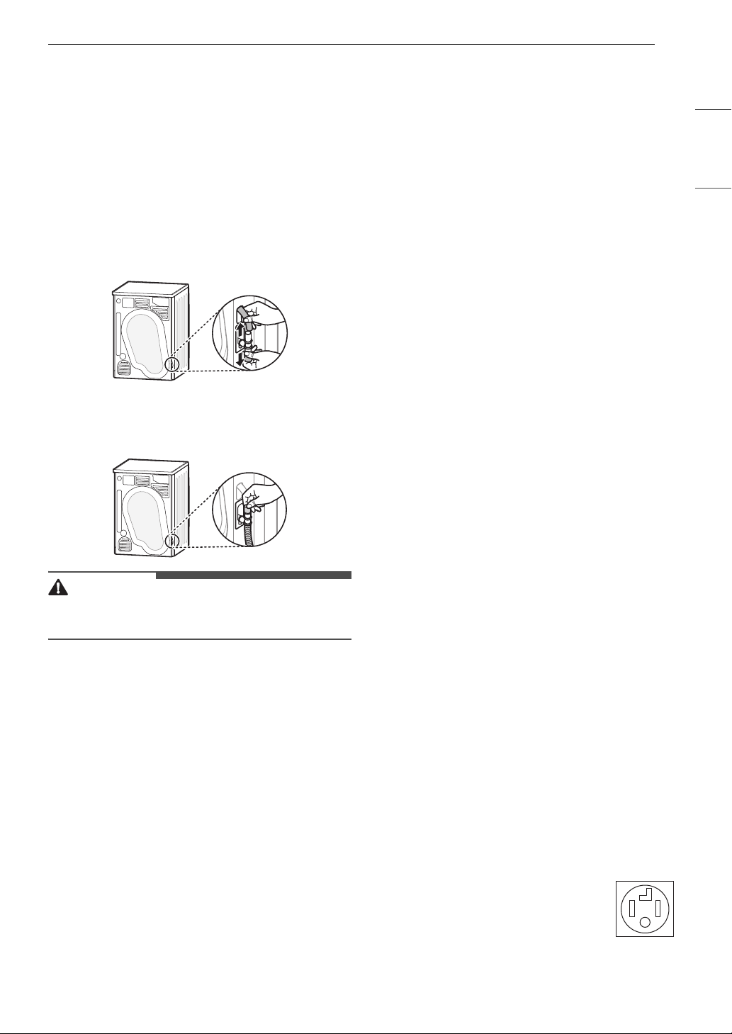
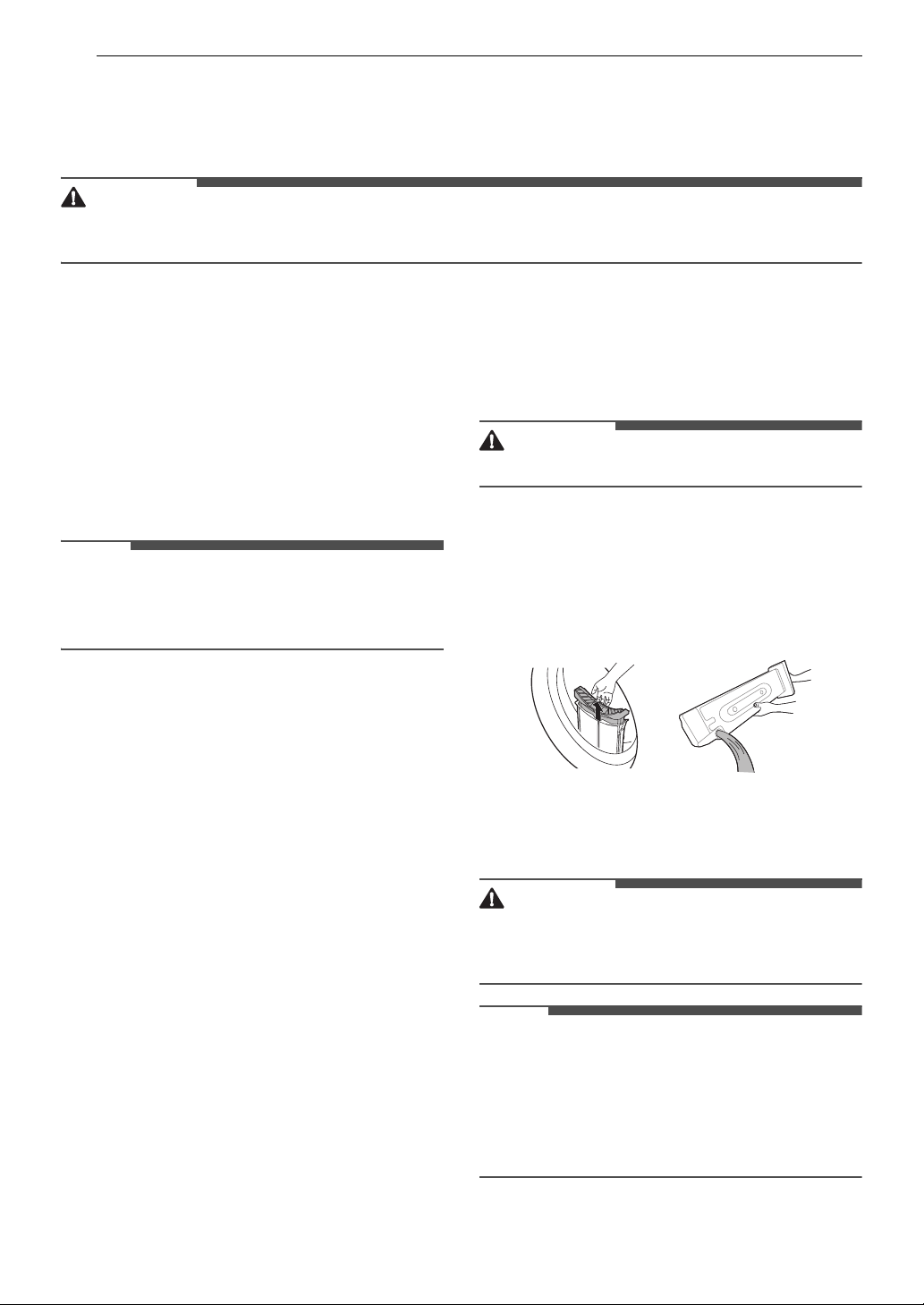
Installing the Optional Drain Hose
Normally, condensed water is pumped up to the
water container where water is collected until
manually emptied. It may be more convenient to
drain water to an external drain, especially when
the appliance is stacked on top of a washing
machine.
Use the connecting T piece to reroute the drainage
as shown below.
1 Remove the anti-backflow cap a and
disconnect the water container hose b from
the T piece.
2 Attach the anti-backflow cap a to the top of
the T piece and connect the optional drain
c to the bottom of the T piece.
hose
• If the drain hose is kinked or pinched, it will not
drain properly.
Connecting Electric Dryers
To reduce the risk of fire or explosion, electric
shock, property damage, injury to persons, or
death when using this appliance, fulfill the
following requirements.
Electrical Requirements
• The wiring and grounding must conform to the
latest edition of the National Electrical Code,
ANSI/NFPA 70 and all applicable local
regulations. Please contact a qualified electrician
to check your home’s wiring and fuses to ensure
that your home has adequate electrical power to
operate the dryer.
• This dryer must be connected to a grounded
metal, permanent wiring system, or an
equipment-grounding conductor must be run
with the circuit conductors and connected to the
equipment-grounding terminal or lead on the
dryer.
• The dryer has its own terminal block that must
be connected to a separate 240 VAC, 60-Hertz,
single-phase circuit, fused at 30 amperes (the
circuit must be fused on both sides of the line).
ELECTRICAL SERVICE FOR THE DRYER SHOULD
BE OF THE MAXIMUM RATE VOLTAGE LISTED ON
THE NAMEPLATE. DO NOT CONNECT THE DRYER
TO 110-, 115-, OR 120-VOLT CIRCUIT.
• If the branch circuit to dryer is 15 ft. (4.5 m) or
less in length, use UL (Underwriters
Laboratories) listed No.-10 AWG wire (copper
wire only), or as required by local codes. If over
15 ft. (4.5 m), use UL-listed No.-8 AWG wire
(copper wire only), or as required by local codes.
Allow sufficient slack in wiring so the dryer can
be moved from its normal location when
necessary.
• The power cord (pigtail) connection between the
wall receptacle and the dryer terminal block IS
NOT supplied with the dryer. Type of pigtail and
gauge of wire must conform to local codes and
with instructions on the following pages.
• Do not modify the plug and internal wire
provided with the dryer.
• The dryer should be connected to a 4-hole
outlet.
• If the plug does not fit the outlet, a proper outlet
will need to be installed by a qualified electrician.
• Connect the power cord to the terminal block.
Each colored wire should be connected to the
same color screw. Wire color indicated on
manual is connected to the same color screw in
the block.
• Grounding through the neutral conductor is
prohibited for: (1) new branch-circuit
installations and (2) areas where local codes
prohibit grounding through the neutral
conductor.
• This dryer is supplied with the neutral wire
grounded. This white ground wire MUST BE
MOVED to the neutral terminal when a 4-wire
cord is to be used, or where grounding through
the neutral conductor is prohibited.
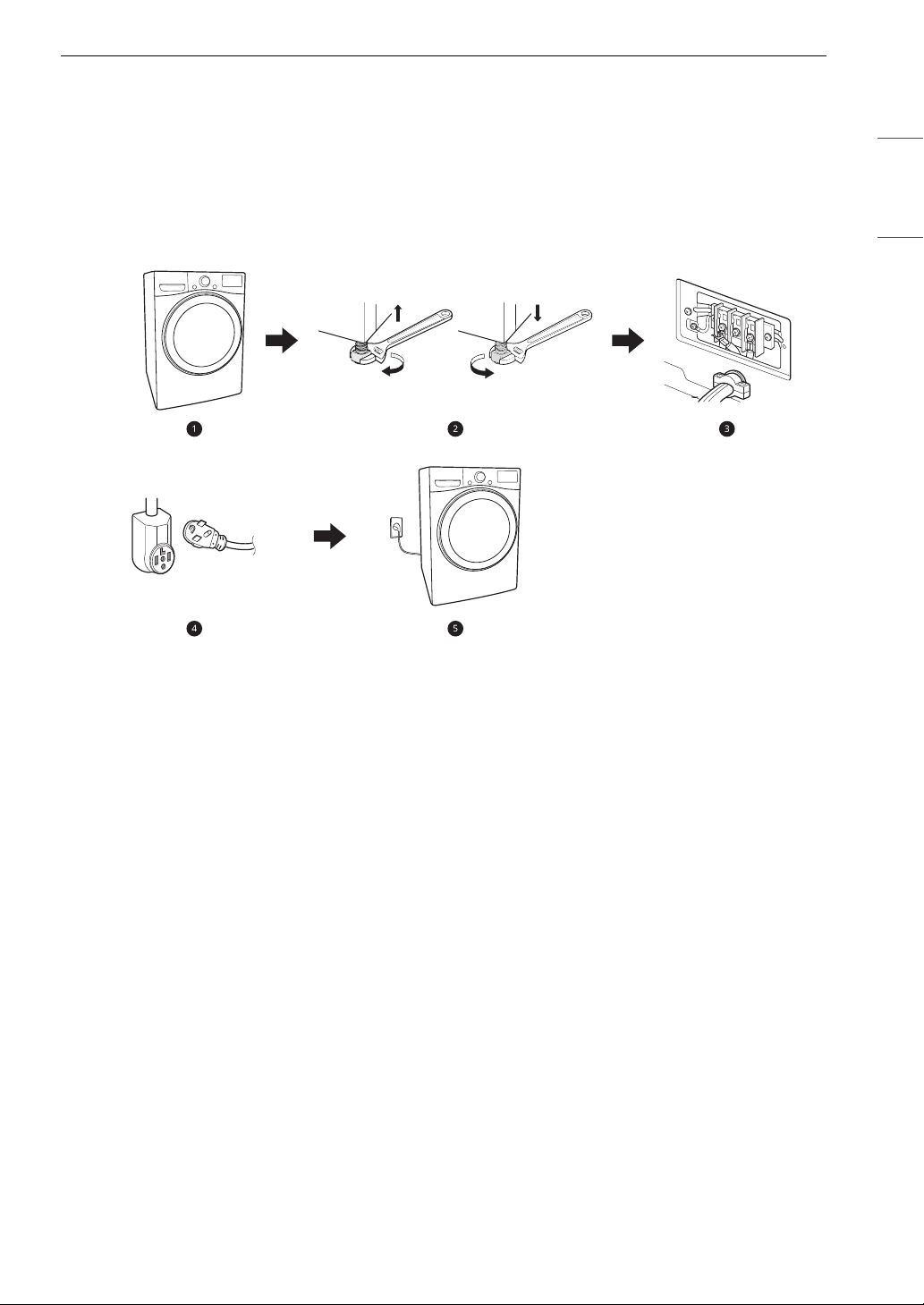
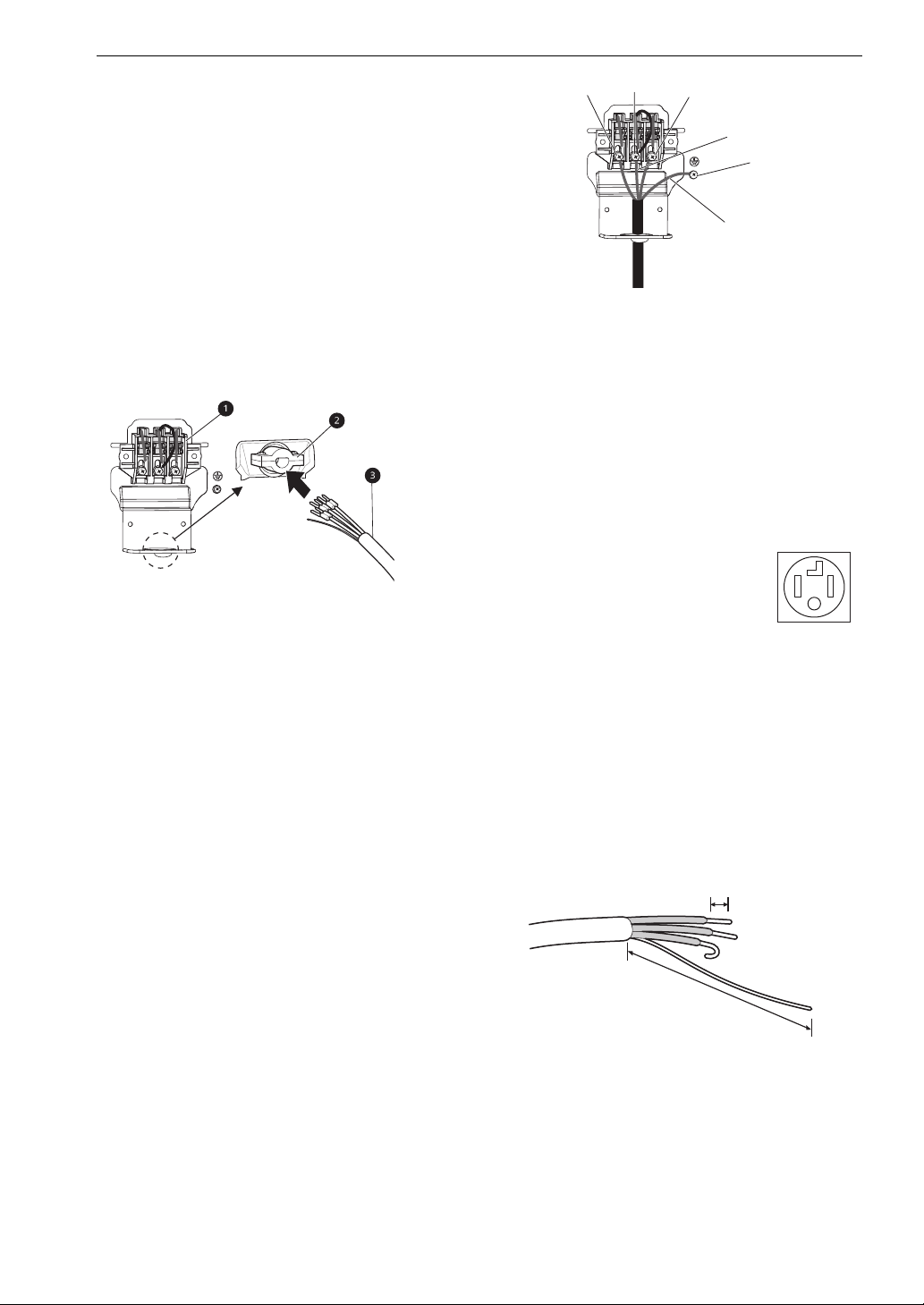
Four-Wire Power Cord
• A UL-listed strain relief is
required.
ENGLISH
18 INSTALLATION
a
b
b
c
d
e
5’’ (12.7 cm)
1’’ (2.5 cm)
a
• Use a 30-amp, 240-volt, 4-wire, UL-listed
power cord with #10 AWG-minimum copper
conductor and closed loop or forked terminals
with upturned ends.
1 Remove the terminal block access cover on
the upper back of the appliance.
2 Install UL-listed strain relief into the power
cord through-hole.
a White Wire moved from Ground Screw
3 Thread a 30-amp, 240-volt, 4-wire, UL-listed
power cord with #10 AWG-minimum copper
conductor through the strain relief.
a Terminal Block
b UL-Listed Strain Relief
c UL-Listed 4-Wire Power Cord
4 Transfer the appliance's ground wire from
behind the green ground screw to the center
screw of the terminal block.
5 Attach the two hot leads (black and red) of the
power cord to the outer terminal block
screws.
b Hot Leads of Power Cord (Black and Red)
c Neutral Wire (White)
d Power Cord Ground Wire
e Ground Screw
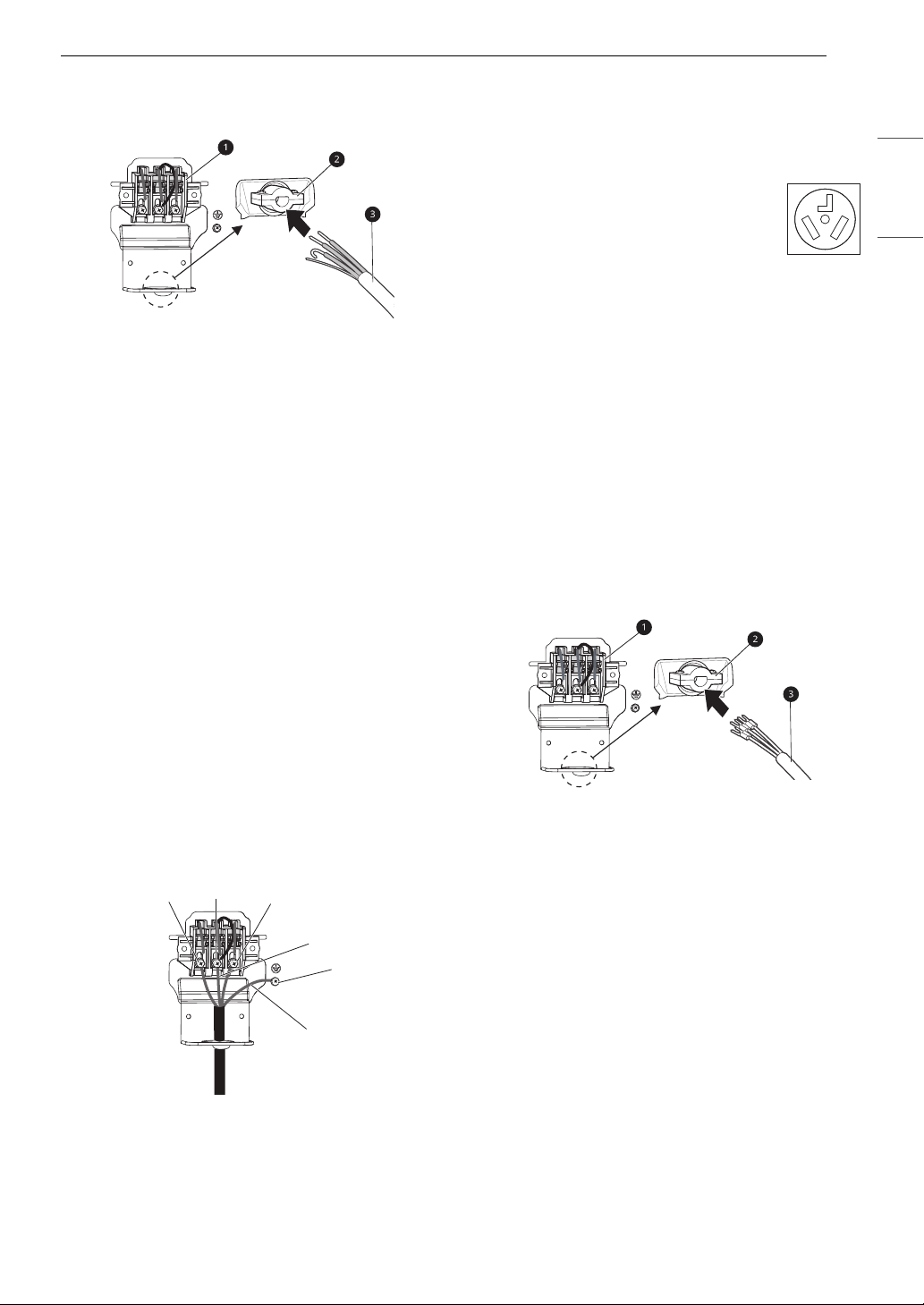
Four-Wire Direct Wire
• A UL-listed strain relief is
required.
•Use UL-listed 4-wire #10 AWG minimum
copper conductor cable. Allow at least 5 ft. (1.5
m) of wire to allow for removal and
reinstallation of the dryer.
1 Remove 5 inches (12.7 cm) of the outer
covering from the wire and remove 5 inches
of insulation from the ground wire. Cut off
approximately 1.5 inches (3.8 cm) from the
other three wires and strip 1 inch (2.5 cm)
insulation from each wire. Bend the ends of
the three shorter wires into a hook shape.
6 Attach the neutral (white) wire to the center
screw of the terminal block
7 Attach the power cord ground wire to the
green ground screw.
8 Tighten all screws securely.
9 Reinstall the terminal block access cover.
a Ground Wire
2 Remove the terminal block access cover on
the upper back of the appliance.
3 Install UL-listed strain relief into the power
cord through-hole.
19INSTALLATION
a
b
b
c
d
e
4 Thread the 4-wire #10 AWG minimum copper
power cable prepared in step 1 through the
strain relief.
a Terminal Block
b UL-Listed Strain Relief
c UL-Listed 4-Wire Power Cord
5 Transfer the appliance's ground wire from
behind the green ground screw to the center
of the terminal block.
6 Attach the two hot leads (black and red) of the
power cord to the outer terminal block
screws.
e Ground Screw
Three-Wire Power Cord
• A 3-wire connection is NOT
permitted on new construction after
January 1, 1996.
• A UL-listed strain relief is required.
• Use a 30-amp, 240-volt, 3-wire, UL-listed
power cord with #10 AWG-minimum copper
conductor and closed loop or forked terminals
with upturned ends.
1 Remove the terminal block access cover on
the upper back of the appliance.
2 Install the UL-listed strain relief into the
power cord through-hole.
3 Thread a 30-amp, 240 volt, 3-wire, UL-listed
power cord with #10 AWG-minimum copper
conductor through the strain relief.
ENGLISH
7 Attach the neutral (white) wire to the center
screw of the terminal block.
8 Attach the power cord ground wire to the
green ground screw.
9 Tighten all screws securely.
10 Reinstall the terminal block access cover.
a White Wire moved from Ground Screw
b Hot Leads of Power Cord (Black and Red)
c Neutral Wire (White)
a Terminal Block
b UL-Listed Strain Relief
c UL-Listed 3-Wire Power Cord
4 Attach the two hot leads (black and red) of the
power cord to the outer terminal block
screws.
5 Attach the neutral (white) wire to the center
terminal block screw.
6 Connect the external ground (if required by
local codes) to the green ground screw.
7 Tighten all screws securely.
d Power Cord Ground Wire
8 Reinstall the terminal block access cover.
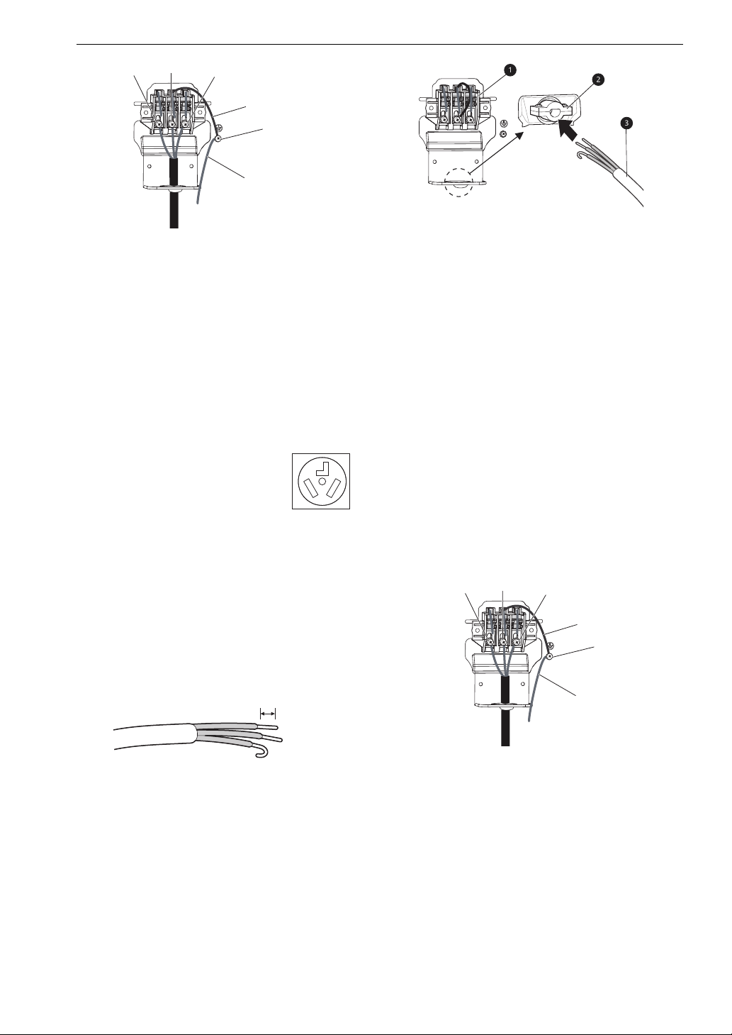
20 INSTALLATION
a
b
b
c
d
e
1’’ (2.5 cm)
a
b
b
c
d
e
a White Wire from Dryer harness
b Hot Leads of Power Cord (Black and Red)
c Neutral Wire (White)
a Terminal block
b UL-listed strain relief
c UL-listed 3-wire power cord
d External Ground Wire (If required by local
codes)
e Ground Screw
Three-Wire Direct Wire
• A 3-wire connection is NOT
permitted on new construction after
January 1, 1996.
• A UL-listed strain relief is required.
• Use UL-listed 3-wire, #10 AWG minimum
copper conductor cable. Allow at least 5 ft. (1.5
m) length to allow for removal and installation
of dryer.
1 Remove 3.5 inches (8.9 cm) of the outer
covering from the wire. Strip 1 inch (2.5 cm)
insulation from each wire. Bend the ends of
the three wires into a hook shape.
5 Attach the two hot leads (black and red) of the
power cord to the outer terminal block
screws.
6 Attach the neutral (white) wire to the center
terminal block screw.
7 Connect the external ground (if required by
local codes) to the green ground screw.
8 Tighten all screws securely.
9 Reinstall the terminal block access cover.
2 Remove the terminal block access cover on
the upper back of the appliance.
3 Install UL-listed strain relief into the power
cord through-hole.
4 Thread the 3-wire, #10 AWG minimum copper
conductor power cable prepared in step 1
through the strain relief.
a White Wire from the appliance harness
b Hot Lead of Power Cord (Black and Red)
c Neutral wire (White)
d External ground wire (If required by local
codes)
e Ground screw

Special Electrical
Requirements
For Mobile or Manufactured Homes
• Any installation in a manufactured or mobile
home must comply with the Manufactured
Home Construction and Safety Standards Title
24 CFR, Part 3280 or Standard CAN/ CSA Z240
MH and local codes and ordinances. If you are
uncertain whether your proposed installation
will comply with these standards, please contact
a service and installation professional for
assistance.
• A 4-wire connection is required for all mobile
and manufactured home installations, as well as
all new construction after January 1, 1996.
• The electrical connection for an electric dryer
must be a 4-wire connection. More detailed
information concerning the electrical connection
is provided in the section Connecting Electric
Dryers.
• To reduce the risk of combustion and fire, the
dryer must be vented to the outside.
• DO NOT vent the dryer under a manufactured
home or mobile home.
• Electric dryers may be vented to the outside
using the back, left, right, or bottom panel.
• Make sure the dryer has adequate access to
outside fresh air to ensure proper operation. The
opening for outside fresh air must be at least 25
sq. in (163 cm
• Please be aware that venting materials are not
supplied with the dryer. You must obtain the
venting materials necessary for proper
installation.
2
).
21INSTALLATION
ENGLISH
Final Installation Check
Once you have completed the installation of the
dryer and it is in its final location, confirm proper
operation with the following tests.
Checking Levelness
Once the dryer is in its final location, recheck the
dryer to be sure it is level. Make sure it is level front
to back and side to side, and that all four leveling
feet are in firm contact with the floor.
22 OPERATION
WARNING
NOTE
CAUTION
WARNING
NOTE
OPERATION
Before Use
• To reduce the risk of fire, electric shock, or injury to persons, read the IMPORTANT SAFETY
INSTRUCTIONS before operating this appliance.
Operation Overview
1 Ensure the lint filter and water container are
clean.
• Open the door and ensure the lint filter is
clean. When the filter is full with lint, drying
times will be longer than usual.
• Pull out the water container and empty the
condensed water. When the water
container is full, the appliance may stop
during the cycle.
• In some cases, the E icon may appear on the
control panel to indicate that the water
container needs to be emptied.
2 Place the clothes into the drum after sorting
and close the door.
• Make sure that clothing is pushed entirely
into the drum and away from the door seal
area. Clothing that gets stuck between the
door and seal may be damaged or damage
the seal.
• Clothes should be sorted by fabric types
and desired dryness level.
• All strings and attached belts of clothes
should be well tied and secured before
being put into the drum.
5 Press the Start/Pause button to start the
drying cycle.
6 After the drying cycle has finished, open the
door and unload the clothes.
• Be careful! The drum inside may still be hot.
7 Press the Power button to turn the appliance
off.
8 Clean the lint filter and empty the water
container.
9 To help prevent odors, leave the dryer door
slightly open to help air out the drum after
use.
• For safety, do not allow children or animals to
climb inside the appliance. They could be injured
or damage the appliance.
3 Press the Power button to turn the appliance
on.
• Depending on the model, the Power button
may light up to indicate that the appliance is
ready to dry.
4 Choose a drying cycle by turning the cycle
selector knob.
• If you press the Start/Pause button without
choosing a cycle, the appliance will proceed
with the Normal cycle. Please refer to the
cycle table for detailed information.
• The final part of the dry cycle does not use heat.
This cool down period helps prevent damage to
clothing.
• A high ambient temperature and a small room
may both increase drying time as well as energy
consumption.
23OPERATION
NOTE
NOTE
Loading the Dryer
• Do not overload the appliance for the best
drying performance and most efficient energy
usage.
General Tips
• Combine large and small items in the same load.
• Close zippers, hooks and drawstrings to prevent
these items from snagging or tangling on other
clothes.
• Damp clothes will expand as they dry. Do not
overload the dryer; clothes require room to
tumble and dry properly.
Grouping Similar Items
For the best drying results, and to reduce the
possibility of damage to clothing, sort clothes into
loads that can be dried with the same drying cycle.
Different fabrics have different care requirements,
and some fabrics will dry more quickly than others.
Woolen Items
• Always follow fabric care labels before drying
woolen items in a dryer. After the cycle, the
items may still be damp. Do not repeat the cycle.
Pull the items to their original shape if needed
and lay them flat to finish drying.
- Curtains and tablecloths
- Bath mats
Fiberglass
• Do not dry fiberglass articles in your dryer. Glass
particles left in the dryer could be picked up by
your clothes the next time you use the dryer and
irritate your skin.
Fabric Care Labels
• Sort and dry laundry according to care labels,
size, and fabric type. Do not overload the dryer.
This will save energy and time and give the best
drying performance.
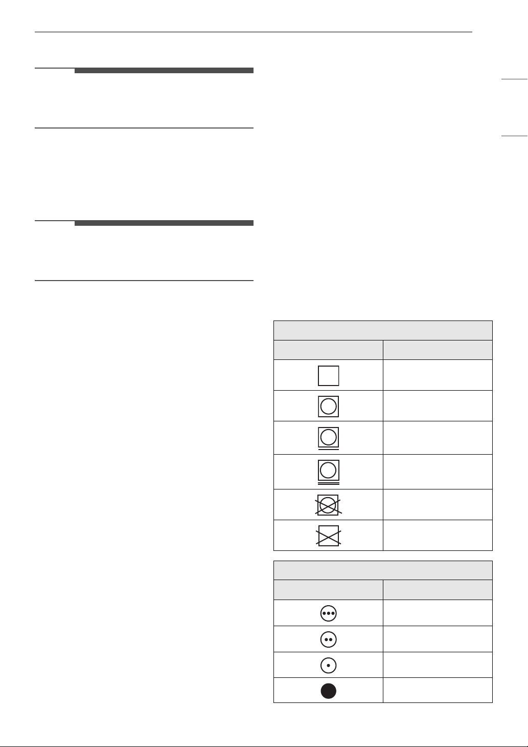
Fabric Care Labels
Many articles of clothing include a fabric care label.
Using the chart below, adjust the cycle and option
selections to care for your clothing according to
the manufacturer's recommendations.
Tumble Dry
Label Directions
Dry
Normal
Permanent Press /
Wrinkle Resistant
Gentle / Delicate
ENGLISH
Woven and Loopknit Materials
• Some woven and loopknit materials may shrink,
depending on quality.
Permanent Press and Synthetics
• Do not overload your dryer. Take out permanent
press items as soon as the dryer stops to reduce
wrinkles.
Baby Clothes and Nightgowns
• Always check the manufacturer’s instructions.
Rubber and Plastics
• Do not dry any items made from or containing
rubber or plastics such as:
- Aprons, bibs and chair covers
Do not tumble dry
Do not dry (used with
do not wash)
Heat Setting
Label Directions
High
Medium
Low
No Heat / Air
24 OPERATION
NOTE
NOTE
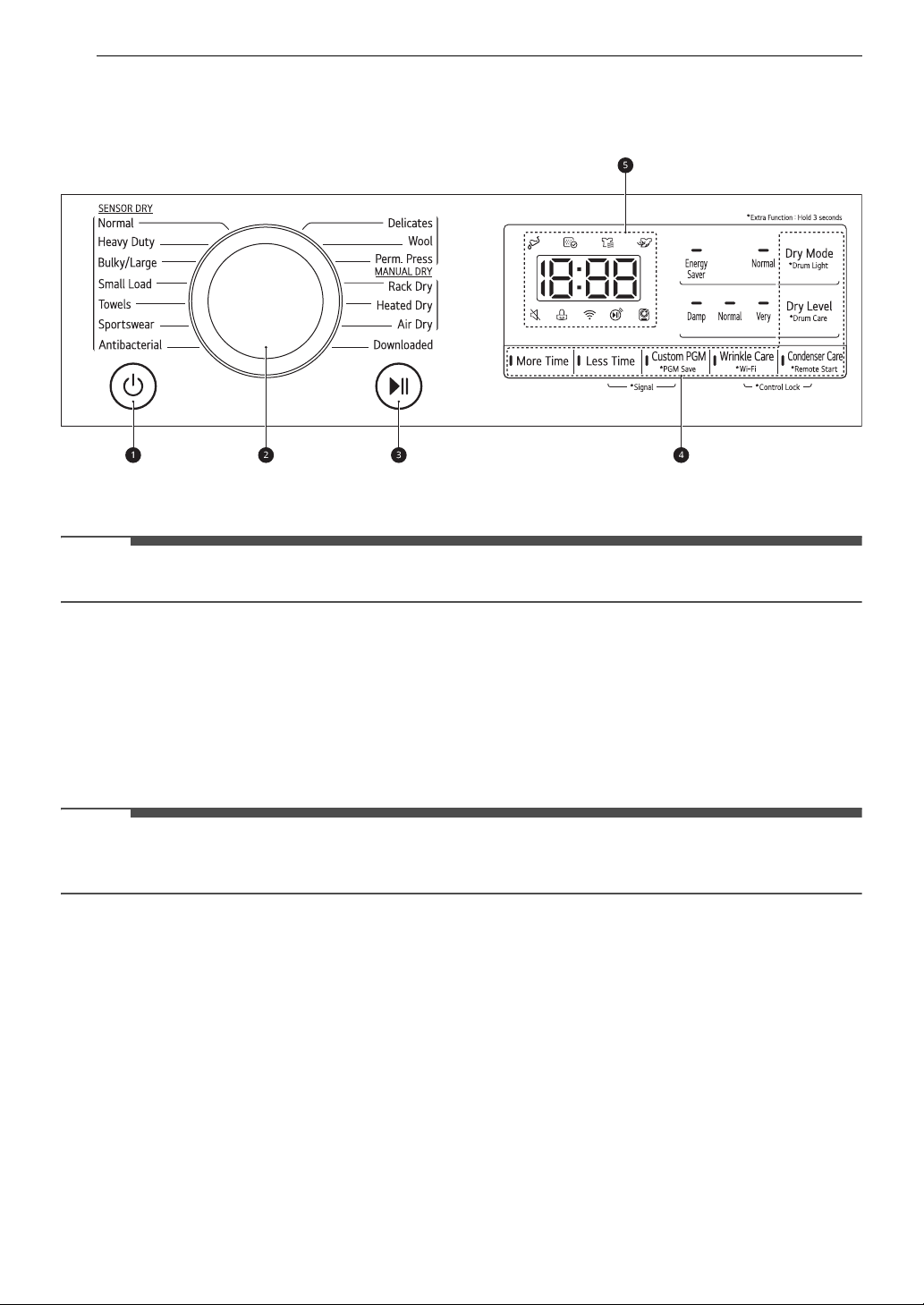
Control Panel
Control Panel Features
a Power Button
• Press the button to turn the appliance on. Press again to turn the appliance off.
• Pressing the Power button during a cycle will cancel that cycle and any load settings will be lost.
b Cycle Selector Knob
• Turn this knob to select the desired cycle. Once the desired cycle has been selected, the standard
presets will be shown in the display. On Manual Dry cycles, these settings can be adjusted using the
cycle modifier buttons anytime before starting the cycle.
c Start/Pause Button
• Press this button to start the selected cycle. If the appliance is running, use this button to pause the
cycle without losing the current settings.
• If you do not press the Start/Pause button to resume a cycle within a certain time, the appliance turns
off automatically and all cycle settings are lost.
d Extra Options and Functions / Cycle Modifier Buttons
• Use these buttons to select the desired options for the selected cycle. Not all options are available for
each cycle.
• Remote Start
- With the LG ThinQ app, you can use a smartphone to control your appliance remotely.
• Wi-Fi
- Press and hold the Wrinkle Care button for 3 seconds to initiate the connection of the appliance to
the LG ThinQ application.
e Time and Status Display
• The display shows the settings, estimated time remaining, options, and status messages for the
appliance. When the appliance is turned on, the default settings in the display will illuminate.
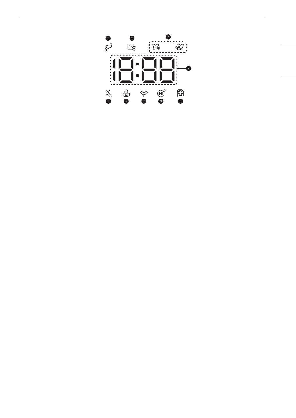
Time and Status Display
a Water Full Indicator
•
E lights up at the beginning of a cycle to remind you to empty the water container before drying. It
also lights up when the water container is full and needs to be emptied.
b Lint Filter Status Indicator
•
K lights up at the beginning of the cycle to remind you to check the lint filter. It also lights up if the
lint filter needs to be cleaned or is missing.
- If the lint filter is not inserted, the icon will light up and the appliance will not operate.
c Cycle Status Indicators
•
@ lights up when the appliance is in the drying stage.
25OPERATION
ENGLISH
•
= lights up when the appliance is in the cool down stage. After = lights up, the appliance can
operate for up to 20 minutes.
d Estimated Time Remaining
• When a drying cycle is selected, the estimated drying time for the selected cycle is displayed. This
time will change if you select extra options for the cycle.
• The cycle time on Sensor Dry cycles may fluctuate as the appliance recalculates drying time for
optimal results.
e q lights up when the button and end-of-cycle sounds are turned off.
f i lights up when the control panel is locked.
g f lights up when the appliance is connected to Wi-Fi network at home.
h w lights up when the remote control feature is activated.
i O lights up while the Drum Care function is operating.
26 OPERATION
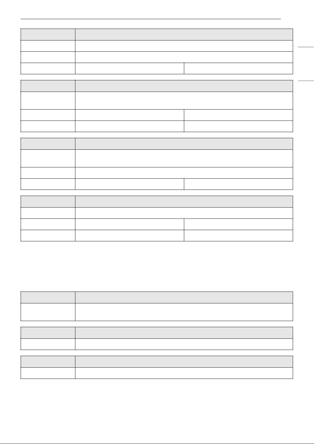
Drying Cycles
Turn the knob or press the button to select the desired cycle. When you select a drying cycle the light for
the corresponding drying cycle will turn on.
Sensor Dry Cycles
Sensor dry cycles utilize LG's unique dual sensor system to detect and compare the moisture level in
clothes and in the air and adjust the drying time as needed to ensure superior results. The appliance
automatically sets the dryness level and temperature at the recommended setting for each cycle. The
estimated time remaining will be shown in the display.
Cycle Normal
Description Use this cycle for drying all normal items such as cotton, linen, shirts, jeans or mixed
loads, except delicate fabrics such as wool or silk.
Dry Level Default: Normal Available: All
Dry Mode Default: Energy Saver Available: All
Cycle Heavy Duty
Description Use this cycle for drying heavy-duty clothes like jeans or garments that need extra
drying.
Dry Level Not adjustable
Dry Mode Default: Energy Saver Available: Energy Saver
Cycle Bulky/Large
Description Use this cycle for drying blankets or bulky items such as pillows, blankets, comforters,
sheets or pet bedding.
Dry Level Not adjustable
Dry Mode Default: Normal Available: Normal
Cycle Small Load
Description Use this cycle for drying light or small items. (up to 3 items)
Dry Level Not adjustable
Dry Mode Default: Normal Available: Normal
Cycle Towels
Description Use this cycle for drying towels.
Dry Level Not adjustable
Dry Mode Default: Energy Saver Available: Energy Saver
Cycle Sportswear
Description Use this cycle for drying special garments for sports and outdoor wear.
Dry Level Not adjustable
Dry Mode Default: Energy Saver Available: Energy Saver
Cycle Antibacterial
27OPERATION
Description Using this cycle helps to reduce bacteria.
Dry Level Not adjustable
Dry Mode Default: Normal Available: Normal
Cycle Delicates
Description Use this cycle for drying dress shirts/blouses, nylons, lingerie, or sheer and lacy clothes
which can easily be damaged.
Dry Level Default: Normal Available: All
Dry Mode Default: Normal Available: Normal
Cycle Wool
Description Use this cycle for drying shrinkable woolen or hand-washable items requiring delicate
care.
Dry Level Not adjustable
Dry Mode Default: Energy Saver Available: Energy Saver
Cycle Perm. Press
Description Use this cycle to minimize wrinkles when drying tablecloths or wrinkle-free clothes.
ENGLISH
Dry Level Default: Normal Available: All
Dry Mode Default: Normal Available: Normal
Manual Dry Cycles
Use Manual Dry cycles to select a specific amount of drying time and a drying temperature. When a
Manual Dry cycle is selected, the actual time remaining in your cycle appears on the display. You can
change the actual time in the cycle by pressing the More Time or Less Time buttons.
Cycle Rack Dry
Description Use this cycle to dry clothes without tumble action. It is suitable for all fabrics that need
refreshing.
Cycle Heated Dry
Description Use this cycle to dry clothes that can be tumble dried using heat.
Cycle Air Dry
Description Use this cycle to dry all fabrics that can be tumble dried without using heat.
28 OPERATION
NOTE
• If the load is less than 1 kg, please use the Heated Dry. Wool items should be dried using the Wool cycle
and heat-sensitive fabrics including silk, underwear and lingerie should be dried using the Delicates
cycle. For best results, and to avoid damaging clothes, follow the recommended load size when selecting
a cycle.
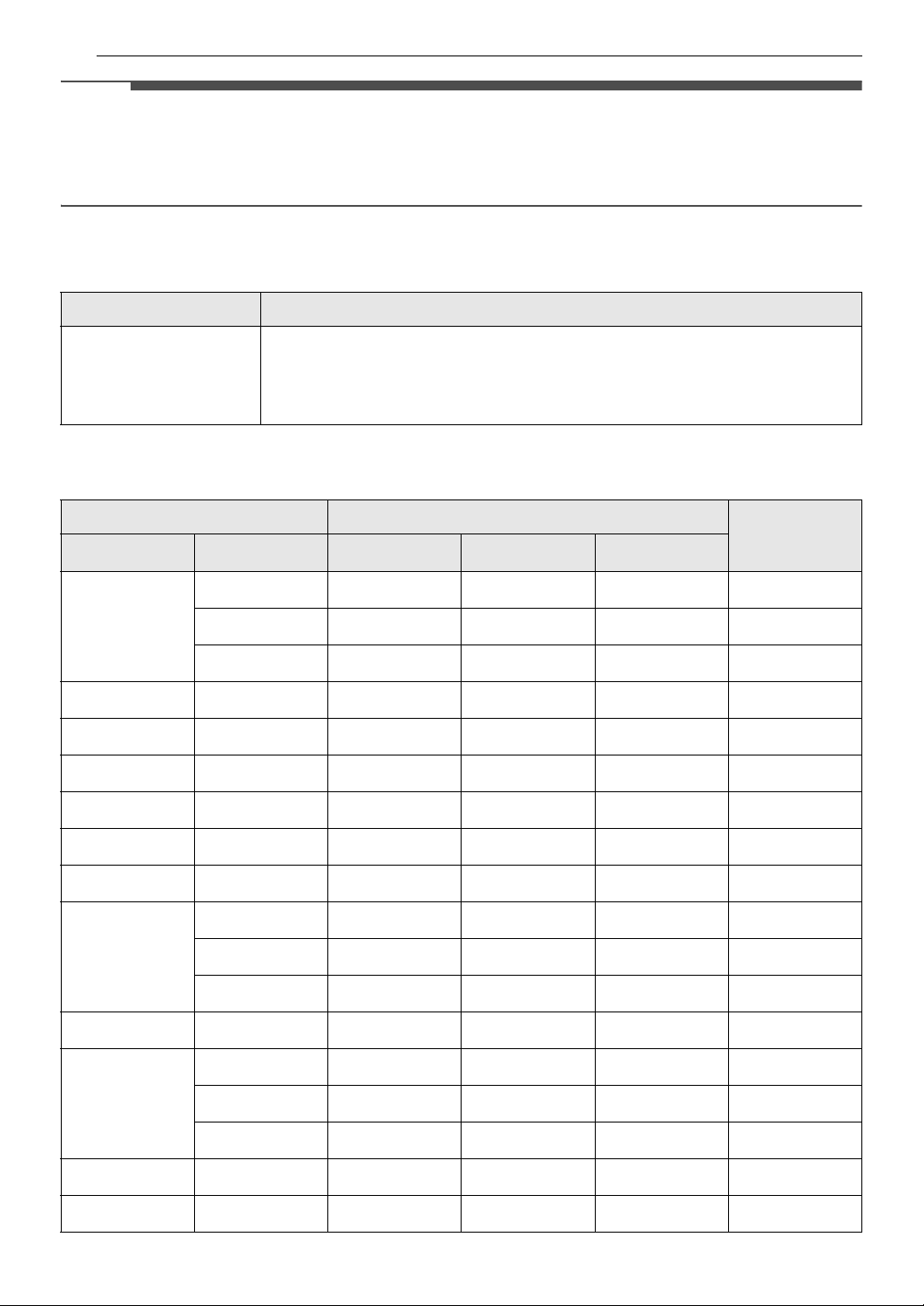
Special Drying Cycles
Cycle Downloaded
Description This cycle allows you to download a new and specialized drying cycle to your
appliance with a smartphone.
• Refer to the LG ThinQ smartphone application to see the cycles available
for download.
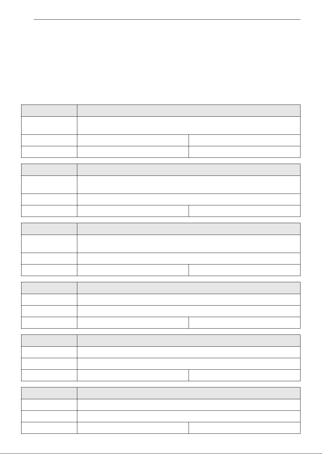
Selectable Drying Options
Cycle Dry Mode
Cycle Dry Level Off
Energy Saver
†
Normal
Wrinkle Care
Normal Very
Normal
Damp
Heavy Duty -
Bulky/Large -
Small Load -
Towels -
Sportswear -
Antibacterial -
Delicates Very
Normal
Damp
Wool -
Perm. Press Very
Normal
###
###
###
##
##
##
##
##
##
##
##
##
##
##
##
Damp
Rack Dry -
Heated Dry -
##
##
###

29OPERATION
Cycle Dry Mode
Cycle Dry Level Off
Air Dry -
† This option helps to reduce the energy used when drying clothes by circulating the refrigerant at a lower
speed than in the Normal mode. When this option is selected, the drying time will increase.
##
Energy Saver
†
Normal
Wrinkle Care
ENGLISH

30 OPERATION
NOTE
NOTE
NOTE
Options and Extra Functions
Your dryer includes several additional cycle
options to customize cycles to meet your individual
needs.
Select the desired option after selecting the
desired cycle and settings.
• The LED for the option will light up when the
option is selected.
• To protect your garments, not every option is
available with every cycle.
• A chime will sound twice and the LED will not
light up if the selected option is not allowed for
the selected cycle.
Dry Level
Use this option to select the dryness level for the
cycle. Press the Dry Level button repeatedly to
scroll through available settings.
• This option is only available with the Normal,
Delicates, and Perm. Press cycles.
• The appliance will automatically adjust the cycle
time according to the selected dryness level.
Selecting Very will increase the cycle time, while
Damp will decrease the cycle time.
•Use the Damp setting for items that you wish to
iron.
Wrinkle Care
Selecting this option will tumble the load
periodically for up to 2 hours after the selected
cycle, or until the door is opened. This is helpful in
preventing wrinkles when you are unable to
remove items from the dryer immediately.
Press the Wrinkle Care button before you start a
drying cycle.
• When the option is set, a rectangle with a
dashed line and ENd appears on the display until
the feature is off.
• When the option is set, only the Power button
works after the drying cycle ends.
• When a drying cycle is running, pause the cycle
first to set the option.
• Always turn off the appliance before unloading
the clothes.
Signal On/Off
The appliance plays a melody when the drying
cycle is finished. The buttons make a sound each
time they are pressed. Use this button to turn the
melody and button tones on or off.
• To turn on/off, press and hold the Less Time and
Custom PGM buttons for 3 seconds at the same
time.
• When the signal is muted,
display.
q lights up on the
Dry Mode
Use this option to help reduce energy
consumption when drying clothes.
• Normal: Dry clothes with recommended
settings.
• Energy Saver: Dry clothes with recommended
settings while circulating the refrigerant at a
lower speed than Normal mode. When the
option is selected, the drying time will increase.
More Time / Less Time
Use these buttons to increase or decrease drying
time in 1 minute increments when you use manual
drying cycles such as Rack Dry, Heated Dry and
Air Dry.
Drum Light
The drum is equipped with a light that illuminates
when the appliance is turned on. The light
automatically turns off when the dryer door is
closed and the cycle starts.
To turn on the light during a cycle, press and hold
the Dry Mode button for 3 seconds. The drum
light will turn on and then turn off automatically
after 4 minutes.
Custom PGM
Save special combinations of settings that are
used frequently as a custom program.
 Loading...