How it Works
Log In / Sign Up
Buy Points
How it Works
FAQ
Contact Us
Questions and Suggestions
Users
LG
Loading...
D
DLGX5966W
2
DLGX6002V
5
DLGX6002W
3
DLGX7188
DLGX7188RM
4
DLGX7188WM
4
DLGX7201
DLGX7601
DLGX7601E
DLGX7601KE
DLGX7601VE
DLGX7601WE
2
DLGX7701E
3
DLGX7701KE
DLGX7701VE
2
DLGX7701WE
3
DLGX7711VE
2
DLGX7801
DLGX7801VE
2
DLGX7801WE
2
DLGX7901BE
2
DLGX8001
4
DLGX8001V
9
DLGX8001W
7
DLGX8101V
3
DLGX8101W
2
DLGX8388CM
2
DLGX8388NM
4
DLGX8388RM
2
DLGX8388WM
4
DlGx8501
DLGX8501V
DLGX9001
3
DLGX9001V
6
DLGX9001W
2
DLGX9501
DLGX9501K
2
DlGY1202
3
DLGY1202V
4
DLGY1202W
4
DLGY1702
2
DLGY1702E
2
DLGY1702V
4
DLGY1702VE
4
DLGY1702W
DLGY1702WE
3
DLGY1902E
DLGY1902KE
DLGY1902WE
2
DLGY2139EK1
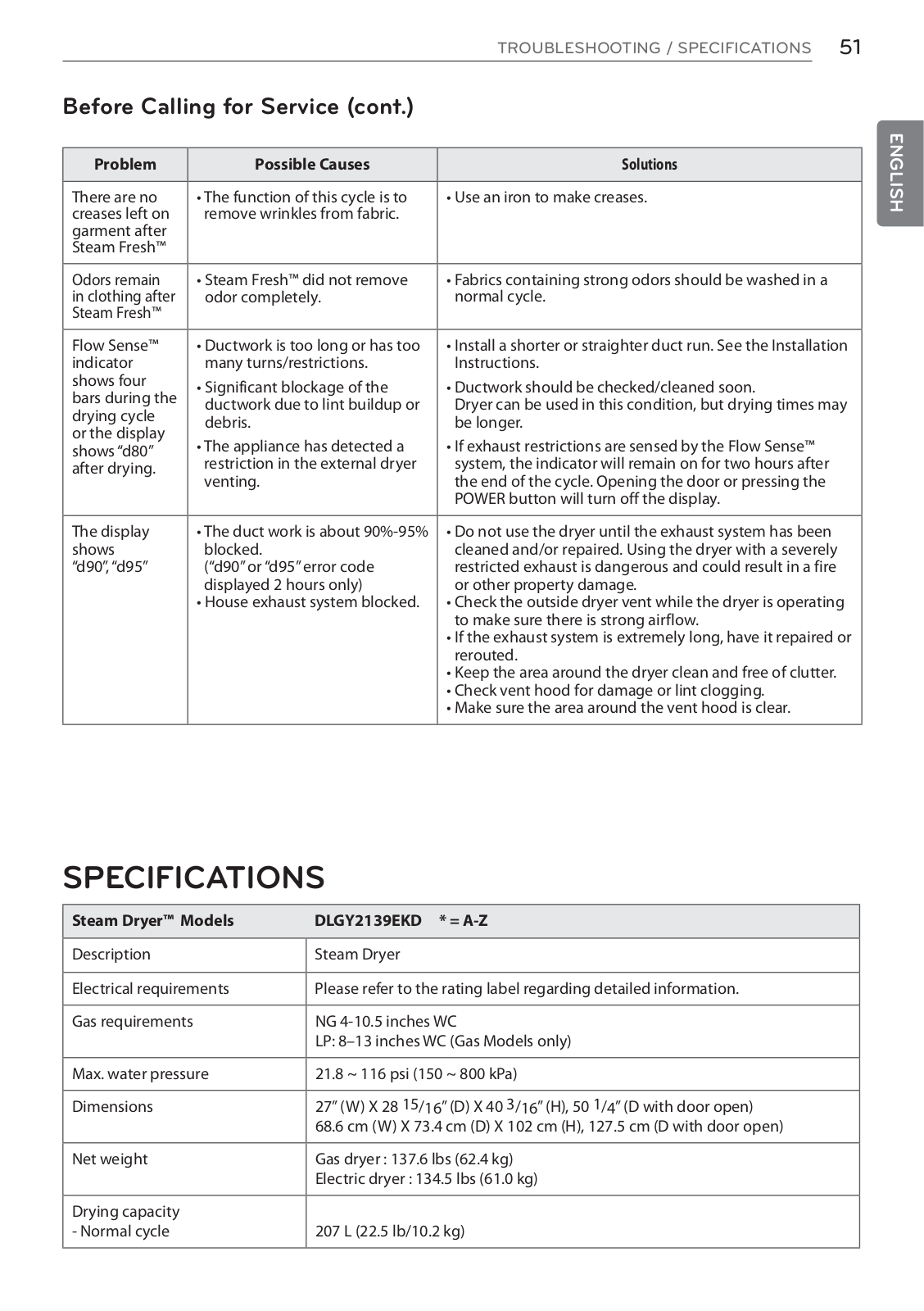
DLGY2139EKD
DLHC1455
DLHC1455P
DLHC1455V
4
DLHC1455W
3
DLHC5502B
DLHC5502V
DLHC6702B
dlhx4072
4
DLHX4072V
4
DLHX4072W
5
dLite
3
DLO2602L
DLO2602R
DLO2602W
DM-01G
3
DM01K
DM02H
2
DM07RP.NSJ
DM09RP
4
DM09RP.NSJ
DM110
4
DM110Q
DM112
DM120
DM12RP
3
DM12RP.NSJ
DM150
3
DM150C
DM1530
7
DM160
2
DM18RP
3
DM18RP.NSK
DM2130
7
DM2350A-PZ
DM2350D
6
DM2350DM
DM2350D-PC
DM2350D PCM
DM2350D-PR
DM2350D PRM
DM2350D-PS
2
DM2350D-PSN
DM2350D-PU
2
DM2350D-PZ
13
DM2350D PZM
DM2352D
10
DM2352D-PZ
16
DM-341
DM-L200
5
Loading...
Loading...
Nothing found
DLGY2139EKD
Owner's manual
108 pgs
12.33 Mb
0
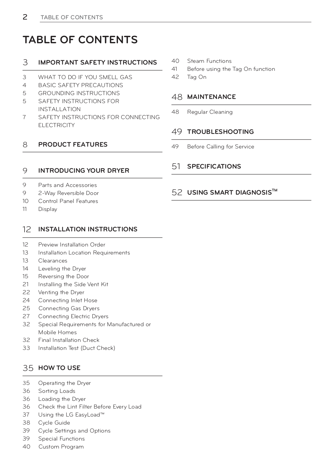
Table of contents
Loading...
LG DLGY2139EKD Owner's manual
...
LG Owner's manual
Download
Specifications and Main Features
Frequently Asked Questions
User Manual
Download
Loading...
+
hidden pages
Unhide
You need points to download manuals.
1 point = 1 manual.
You can buy points or you can get point for every manual you upload.
Buy points
Upload your manuals
 Loading...