

LG DLG2102W Owner’s Manual
DRYERS
USER'SGUIDE&
INSTALLATioNINSTRUCTIONS
Before beginning JnstaJJatJon, read these
instructions carefuliv. This will simplify installation
and ensure that the dryer is installed correctly and
safely. Leavethese instructions near the dryer
after installation for future reference.
SECADORAS
GUjADE[ USUARIOE
INSTRUCclONESDEINSTALAclON
TOcontact LG Electronics, 24 hours a day,
7 days a week:
1=800=243=0000
Or visit us on the Web at: us.lge.com
NQmero telef6nico de LG Electronics, las 24
horas del dia, 7 dias a la semana:
1=800=243=0000
O visitenos en la Web en: us.lge.com
To contact LG Electronics, 24 hours a day,
7 days a week :
1=888=LGCANADA
Or visit us on the Web at : ca.lge.com
Pour contacter LG Electronics, 24 heures
Par jour, 7 jours par semaine :
1=888=LGCANADA
Ou visitez notre site Web a I'addresse :
ca.lge.com
Antes de comenzar [a instalacion, lea atentamente
estas instrucciones. Esto simplJficara la instalacion
V asegurar_l que [a secadora est_l Jnstalada
en forma correcta V segura. Conserve estas
JnstruccJones cerca de la secadora luego de la
instalacion para futuras consultas.
SECHEUSES
GUIDEDEL'UTI[ISATEURET
DIRECTIVESD'INSTALLATION
Avant de commencer a installer votre secheuse, IJsez
attentivement ces instructions. Cela simplifiera votre
installation et assurera que la secheuse est installee
correctement et en route securite. Conservez ces
instructions a proximite de la secheuse apres son
installation, pour reference future.
Models/Modelos/IViodeles
Electric/Electrica/[lectrlque
DLE2101W
DLE2101R
DLE2101S
DLE2101L
(;as/(;as/i__oaz
DLG2102W
DLG2102R
DLG2102S
DLG2102L
INTRODUCTION
iMPORTANT SAFETY iNSTRUcTiONS
Basic safety Precautions ....................................... 3
What to Do if You Smell Gas .................................. 4
Grounding instructions ........................................... 5
Safety instructions for installation ...................... 5, 6
Safety instructions for Connecting Electricity ....... 7
PARTSAND FEATURES
Key Parts and Components ................................... 8
THANKYOU!
Congratulations on your purchase
and welcome to the LG family. Your
INSTALLATION INSTRUCTIONS
Choose the Proper Location .................................. 9
Clearances ............................................................. 9
installation With Optional
Pedestal Base or Stacking Kit .............................. 10
Leveling the Dryer ................................................ 11
Reversing the Door Swing .................................... 11
Changing the Dryer Vent Location ....................... 12
Venting the Dryer ............................................ 13, 14
Connecting Gas Dryers .................................. 15, 16
Connecting Electric Dryers .............................. 17-21
Special Requirements for Manufactured
or Mobile Homes .................................................. 22
Final installation Check ....................................... 22
HOW TO USE
Sorting Loads ....................................................... 23
Loading the Dryer ................................................. 23
Check the Lint Filter Before Every Load ............... 23
Control Panel Features ......................................... 24
Cycle Guide .......................................................... 25
The LED Display ................................................... 26
Operating the Dryer .............................................. 27
Cycle Setting Buttons .......................................... 28
Custom Program .................................................. 28
Cycle Option Buttons .......................................... 29
USER=MAINTENANCE iNSTRUCTiONS
Regular Cleaning .................................................. 30
new LG Dryer combines the most
advanced drying sensor technology
with simple operation and high
efficiency. By following the
operating and care instructions
in this manual, your dryer will
provide you with many years of
reliable service.
Product Registration Information
Model:
Serial Number:
Date of Purchase:
The model and serial number can be located on the rating
plate inside the front door.
TROUBLESHOOTING
Before Calling for Service ............................... 31, 32
SPECIFICATIONS/OPTIONAL
ACCESSORIES
Key Dimensions and Specifications ..................... 33
Optional Accessories ........................................... 33
Pedestal Installation ....................................... 34, 35
Stacking Kit installation .................................. 36, 37
WARRANTY .............................................38,39
2
I PORTANTSAFETYINSTRUCTIONS
READ ALL iNSTRUCTiONS BEFORE USE
WARNING For yo.r safety,the information in this manual must be
followed to minimize the risk of fire or e×plosion, electric shock, or to prevent
property damage, personal injury, or loss of life.
r Your Safety and the safety of others is very important.
We have provided many important safety messages in this manual and on your appliance. Always read
and obey all safety messages.
This iSthe safety alert symbol.
This symbol alerts you to potential hazards that can kill or hurt you and others.
All safety messages will follow the safety alert symbol and either the word DANGER or WARNING.
These words mean:
_DANGI=R: You can be killed or seriously injured if you don't immediately follow instructions.
A_t,_'ARN|_G: You can be killed or seriously injured if you don't follow instructions.
All safety messages will tell you what the potential hazard is, tell you how to reduce the chance of
injury, and tell you what can happen if the instructions are not followed.
BASIC SAFETY PRECAUTIONS
WARNING:
appliance, follow basic precautions, including the following:
• Read all instructions before using the dryer.
Before use, the dryer must be properly installed
as described in this manual.
Do not place items exposed to cooking oils in
your dryer. Items contaminated with cooking
oils may contribute to a chemical reaction that
could cause a load to catch fire.
Do not dry articles that have been previously
cleaned in, washed in, soaked in, or spotted
with gasoline, dry-cleaning solvents, or other
flammable or explosive substances as they give
off vapors that could ignite or explode.
• Do not reach into the dryer if the drum or any
other part is moving.
Do not repair or replace any part of the dryer
or attempt any servicing unless specifically
recommended in this Use and Care Guide or
in published user-repair instructions that you
understand and have the skills to carry out.
• Do not tamper with controls.
Before the dryer is removed from service or
discarded, remove the door to the drying
compartment.
To reduce the risk of fire, electric shock, or injury to persons when using this
Do not allow children to play on or in the dryer.
Close supervision of children is necessary when
the dryer is used near children.
Do not use fabric softeners or products to
eliminate static unless recommended by the
manufacturer of the fabric softener or product.
Do not use heat to dry articles containing
foam rubber or similarly textured rubber-like
materials.
Keep area around the exhaust opening and
adjacent surrounding areas free from the
accumulation of lint, dust, and dirt.
The interior of the dryer and exhaust vent
should be cleaned periodically by qualified
service personnel.
Do not install or store the dryer where it will be
exposed to the weather.
Always check the inside of the dryer for foreign
objects.
Clean lint screen before or after each load.
5
I PORTANTSAFETYINST UCTIONS
READ ALL iNSTRUCTiONS BEFORE USE
_WARNING For your safety,the information in this manual must be
followed to minimize the risk of fire or explosion, electric shock, or to prevent
property damage, personal injury, or loss of life.
• Do not store or use gasoline or other
flammable vapors and liquids in the
vicinity of this appliance or any other
appliances.
• installation and service must be
performed by a qualified installer,
service agency, or the gas supplier.
WHAT TO DO IF YOU SMELl. GAS:
1. Do not try to light a match or cigarette,
or turn on any gas or electrical
applianceo
2. Do not touch any electrical switches.
Do not use any phone in your building.
3. Clear the room, building, or area of all
occupants.
4. Immediately call your gas supplier
from a neighbor's phone. Follow the
gas supplier's instructions carefully.
5. if you cannot reach your gas
supplier, call the fire department.
4
iMPORTANTSAFETYiNSTRUCTiONS
READ ALL iNSTRUCTiONS BEFORE USE
WARNING For yo.r safety,the information in this manual must be
followed to minimize the risk of fire or explosion, electric shock, or to prevent
property damage, personal injury, or loss of life.
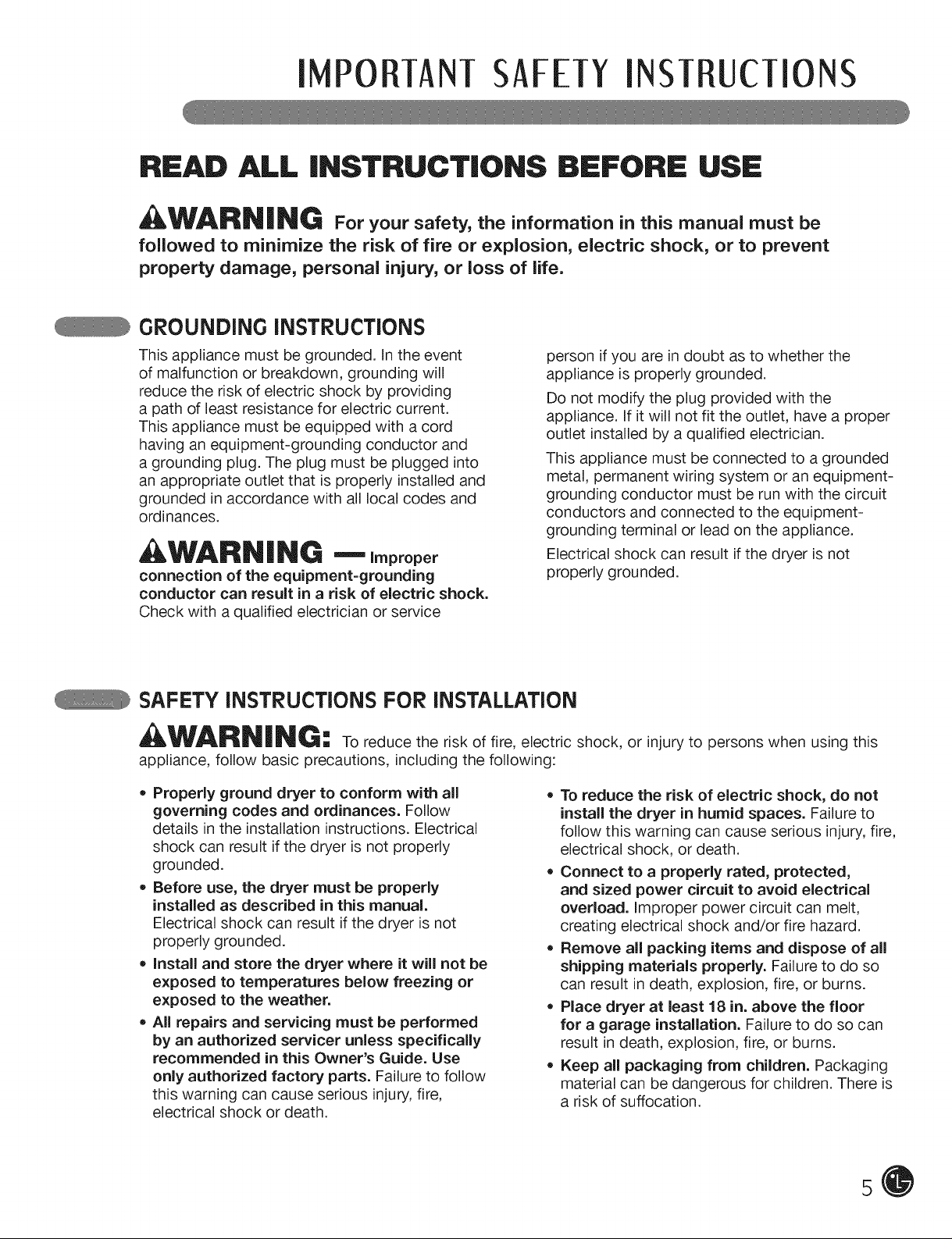
GROUNDING iNSTRUCTiONS
This appliance must be grounded. In the event
of malfunction or breakdown, grounding will
reduce the risk of electric shock by providing
a path of least resistance for electric current.
This appliance must be equipped with a cord
having an equipment-grounding conductor and
a grounding plug. The plug must be plugged into
an appropriate outlet that is properly installed and
grounded in accordance with all local codes and
ordinances.
WARNING --Improper
connection of the equipment=grounding
conductor can result in a risk of electric shock.
Check with a qualified electrician or service
person ifyou are in doubt as to whether the
appliance is properly grounded.
Do not modify the plug provided with the
appliance. If it will not fit the outlet, have a proper
outlet installed by a qualified electrician.
This appliance must be connected to a grounded
metal, permanent wiring system or an equipment-
grounding conductor must be run with the circuit
conductors and connected to the equipment-
grounding terminal or lead on the appliance.
Electrical shock can result if the dryer is not
properly grounded.
SAFETY iNSTRUCTiONS FOR iNSTALLATiON
WARNING: To reduce the risk of fire, electric shock, or injury to persons when using this
appliance, follow basic precautions, including the following:
,, Properly ground dryer to conform with all
governing codes and ordinances. Follow
details in the installation instructions. Electrical
shock can result if the dryer is not properly
grounded.
* Before use, the dryer must be properly
installed as described in this manual.
Electrical shock can result if the dryer is not
properly grounded.
, install and store the dryer where it will not be
exposed to temperatures below freezing or
exposed to the weather.
* All repairs and servicing must be performed
by an authorized servicer unless specifically
recommended in this Owner's Guide. Use
only authorized factory parts. Failure to follow
this warning can cause serious injury, fire,
electrical shock or death.
* To reduce the risk of electric shock, do not
install the dryer in humid spaces. Failure to
follow this warning can cause serious injury, fire,
electrical shock, or death.
* Oonnect to a properly rated, protected,
and sized power circuit to avoid electrical
overload. Improper power circuit can melt,
creating electrical shock and/or fire hazard.
Remove all packing items and dispose of all
shipping materials properly. Failure to do so
can result in death, explosion, fire, or burns.
Place dryer at least 18 in. above the floor
for a garage installation. Failure to do so can
result in death, explosion, fire, or burns.
Keep all packaging from children. Packaging
material can be dangerous for children. There is
a risk of suffocation.
5
I PORTANTSAFETYINST UCTIONS
READ ALL iNSTRUCTiONS BEFORE USE
WARNING For yo.r safety,the information in this manual must be
followed to minimize the risk of fire or explosion, electric shock, or to prevent
property damage, personal injury, or loss of life.
SAFETY iNSTRUCTiONS FOR iNSTALLATiON
Exhaust/Ducting:
, Gas dryers MUST be exhausted to the
outside. Failure to follow these instructions
can result in fire or death.
• The dryer exhaust system must be exhausted
to the outside of the dwelling. If the dryer is
not exhausted outdoors, some fine lint and
large amounts of moisture will be expelled
into the laundry area. An accumulation of
lint in any area of the home can create a health
and fire hazard.
• Use only rigid metal or flexible metal 4-in.
diameter ductwork inside the dryer cabinet
or for exhausting to the outside. Use of
plastic or other combustible ductwork can
cause a fire. Punctured ductwork can cause
a fire if itcollapses or becomes otherwise
restricted in use or during installation.
• Ductwork is not provided with the dryer, and
you should obtain the necessary ductwork
locally. The end cap should have hinged
dampers to prevent backdraft when the dryer
is not in use. Failure to follow these instructions
can result in fire or death.
, The exhaust duct must be 4 in. (10 cm) in
diameter with no obstructions. The exhaust
duct should be kept as short as possible.
Make sure to clean any old ducts before
installing your new dryer. Failure to follow
these instructions can result in fire or death.
• Rigid or semi rigid metal ducting is
recommended for use between the
dryer and the wall. in special installations
when it is impossible to make a connection
with the above recommendations, a UL=
listed flexible metal transition duct may be
used between the dryer and wall connection
only. The use of this ducting will affect drying
time. Failure to follow these instructions can
result in fire or death.
DO NOT use sheet metal screws or other
fasteners which extend into the duct that
could catch lint and reduce the efficiency
of the exhaust system. Secure all joints with
duct tape. For complete details, follow the
Installation Instructions. Failure to follow these
instructions can result in fire or death.
6
iMPORTANTSAFETYiNSTRUCTiONS
READ ALL iNSTRUCTiONS BEFORE USE
WARNING For yo.r safety,the information in this manual must be
followed to minimize the risk of fire or explosion, electric shock, or to prevent
property damage, personal injury, or loss of life.
SAFETY iNSTRUCTiONS FOR CONNECTING ELECTRiCiTY
AWARNING: To reduce the risk of fire, electric shock, or injury to persons when using this
appliance, follow basic precautions, including the following:
• Do not, under any circumstances, cut or
remove the ground prong from the power
cord. To prevent personal injury or damage to
the dryer, the electrical power cord must be
plugged into a properly grounded outlet.
• For personal safety, this dryer must be
properly grounded. Failure to do so can result
in electrical shock or injury.
• Refer to the installation instructions in this
manual for specific electrical requirements
for your model. Failure to follow these
instructions can create an electrical shock
hazard and/or a fire hazard.
• This dryer must be plugged into a properly
grounded outlet. Electrical shock can result if
the dryer is not properly grounded. Have the
wall outlet and circuit checked by a qualified
electrician to make sure the outlet is properly
grounded. Failure to follow these instructions
can create an electrical shock hazard and/or a
fire hazard.
• The dryer should always be plugged into
its own individual electrical outlet which
has a voltage rating that matches the rating
plate. This provides the best performance
and also prevents overloading house wiring
circuits which could cause a fire hazard from
overheated wires.
, Never unplug your dryer by pulling on the
power cord. Always grip plug firmly and pull
straight out from the outlet. The power cord
can be damaged, resulting in a risk of fire and
electrical shock.
• Repair or replace immediately all power
cords that have become frayed or otherwise
damaged. Do not use a cord that shows
cracks or abrasion damage along its length
or at either end. The power cord can melt,
creating electrical shock and/or fire hazard.
• When installing or moving the dryer, be
careful not to pinch, crush, or damage
the power cord. This will prevent injury and
prevent damage to the dryer from fire and
electrical shock.
SAVE THESE iNSTRUCTiONS
7
PARTSAND FEATURES
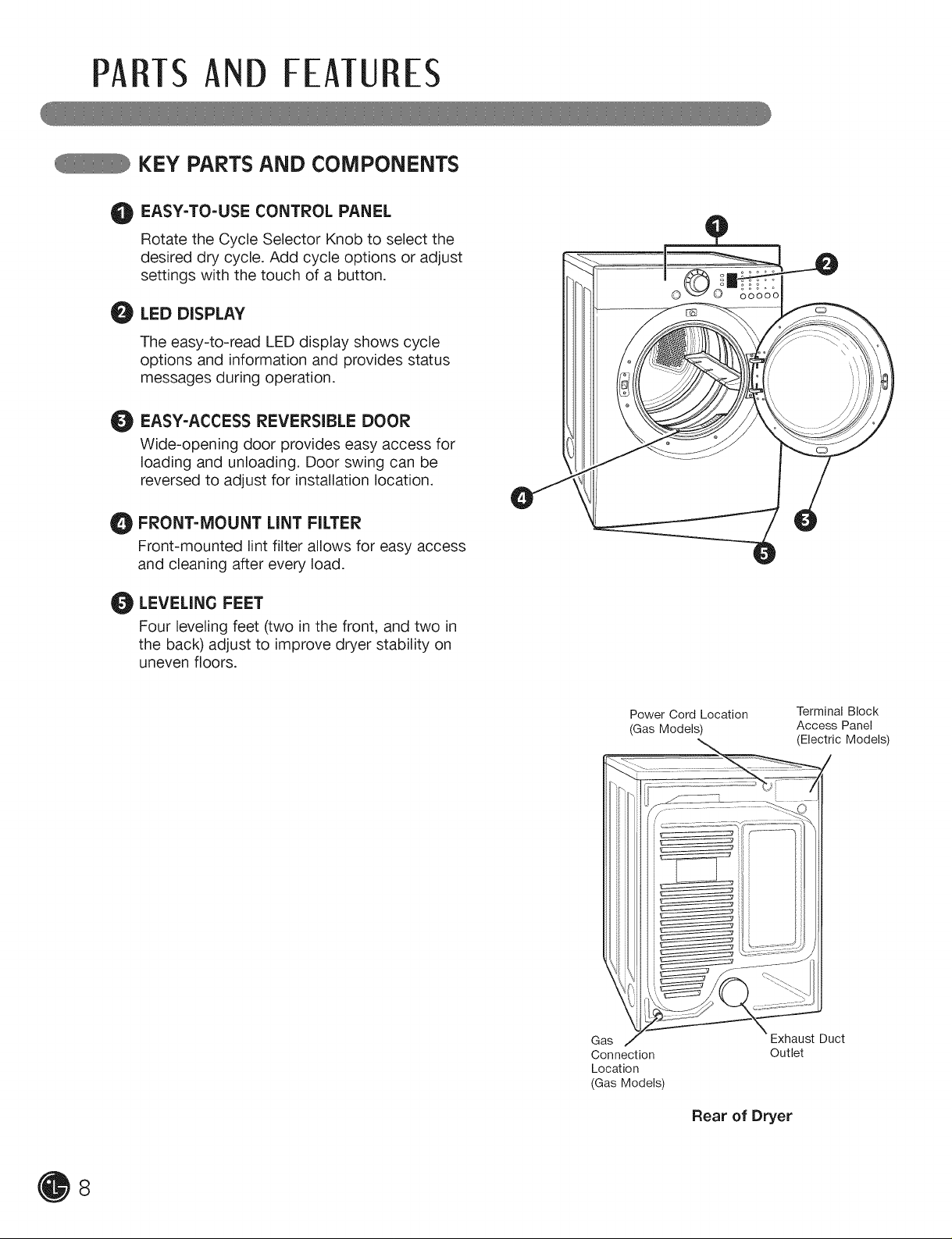
KEY PARTS AND COMPONENTS
EASY-TO-USE CONTROL PANEL
Rotate the Cycle Selector Knob to select the
desired dry cycle. Add cycle options or adjust
settings with the touch of a button.
LED DISPLAY
0
The easy-to-read LED display shows cycle
options and information and provides status
messages during operation.
EASY-ACCESSREVERSIBLE DOOR
O
Wide-opening door provides easy access for
loading and unloading. Door swing can be
reversed to adjust for installation location.
FRONT-MOUNT LINT FILTER
O
Front-mounted lint filter allows for easy access
and cleaning after every load.
LEVELING FEET
O
Four leveling feet (two in the front, and two in
the back) adjust to improve dryer stability on
uneven floors.
Power Cord Location
(Gas Models)
Gas
Connection
Location
(Gas Models)
Terminal Block
Access Panel
(Electric Models)
Exhaust Duct
Outlet
Rear of Dryer
8
INSTAllATION INST UcTIONS
IMPORTANT: Read all installation instructions completely before
installing and Operating your dryer!
It is important that you review this entire manual before installing and using your dryer. Detailed instructions
concerning electrical connections, gas connections, and exhaust requirements are provided on the
following pages.
CHOOSE THE PROPER LOCATION
• Store and install the dryer where it will not be
exposed to temperatures below freezing or
exposed to outdoor weather conditions.
Choose a location with a solid, level floor.
If the dryer is being installed in a garage,
place the dryer at least 18 in. (46 cm) above
the floor.
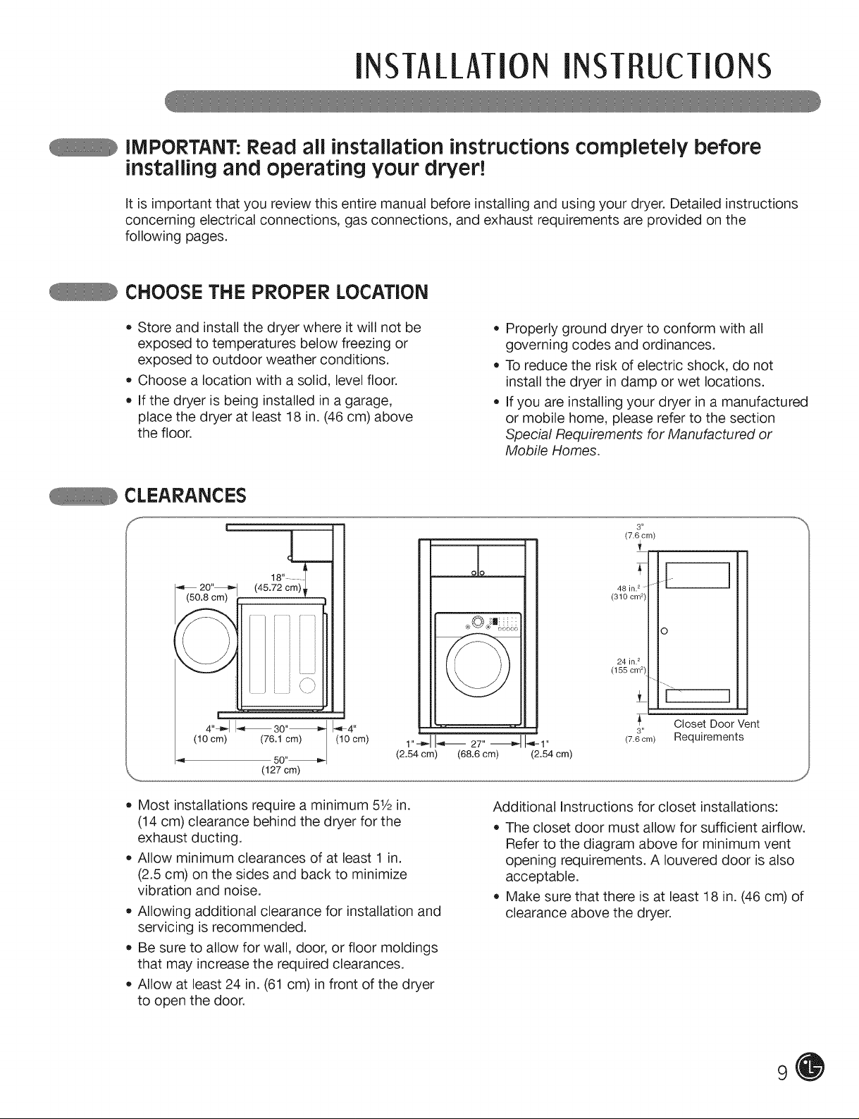
CLEARANCES
S
|
(50.8 _)
4"_-_1I_ 30"_
(10 cm) (76.1 cm)
(127 crn)
50"_
i\ j
(10 cm)
1"-_1I_ 27" _ _-1"
(2.54 cm) (68.6 cm) (2.54 cm)
Properly ground dryer to conform with all
governing codes and ordinances.
To reduce the risk of electric shock, do not
install the dryer in damp or wet locations.
If you are installing your dryer in a manufactured
or mobile home, please refer to the section
Special Requirements for Manufactured or
Mobile Homes.
3"
(7.6 cm)
oo
48 in.2
(310 cm 2)
o
24 in.2
(155 crn2)
t
Closet Door Vent
3"
(7.6 cm) Requirements
l
• Most installations require a minimum 51/2in.
(14 cm) clearance behind the dryer for the
exhaust ducting.
Allow minimum clearances of at least 1 in.
(2.5 cm) on the sides and back to minimize
vibration and noise.
Allowing additional clearance for installation and
servicing is recommended.
Be sure to allow for wall, door, or floor moldings
that may increase the required clearances.
Allow at least 24 in. (61 cm) in front of the dryer
to open the door.
Additional Instructions for closet installations:
The closet door must allow for sufficient airflow.
Refer to the diagram above for minimum vent
opening requirements. A Iouvered door is also
acceptable.
Make sure that there is at least 18 in. (46 cm) of
clearance above the dryer.
9
INSTALLATIONINSTRUCTIONS
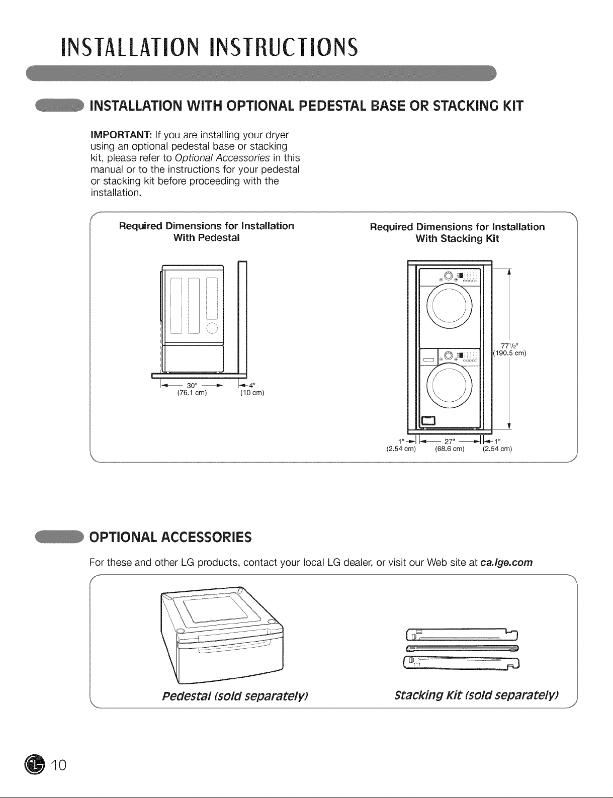
iNSTALLATiON WITH OPTIONAL PEDESTAL BASE OR STACKING KIT
iMPORTANT: If you are installing your dryer
using an optional pedestal base or stacking
kit, please refer to Optional Accessories in this
manual or to the instructions for your pedestal
or stacking kit before proceeding with the
installation.
Required Dimensions for Installation
With Pedestal
......................
I_ 3o"
(76.1 cm) (10 cm)
Required Dimensions for Installation
With Stacking Kit
m m
771/2"
(190.5cm)
E3
1,,-_11_ 27,,-_1 I-,-1,,
(2.54 cm) (68.6 cm) (2.54 cm)
10
OPTIONAL ACCESSORIES
For these and other LG products, contact your local LG dealer, or visit our Web site at caJge.com
f
Pedestal (sold separately) Stacking Kit (sold separatelW
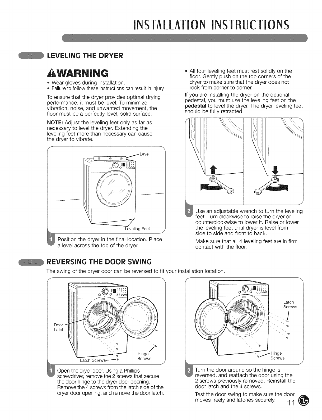
LEVELING THE DRYER
INSTAllATIONINST UcTIONS
, WARNING
• Wear gloves during installation.
Failureto follow these instructions can result in injury.
To ensure that the dryer provides optimal drying
performance, it must be level. To minimize
vibration, noise, and unwanted movement, the
floor must be a perfectly level, solid surface.
NOTE: Adjust the leveling feet only as far as
necessary to level the dryer. Extending the
leveling feet more than necessary can cause
the dryer to vibrate.
Level
®) @ @
Leveling Feet
Position the dryer in the final location. Place
a level across the top of the dryer.
All four leveling feet must rest solidly on the
floor. Gently push on the top corners of the
dryer to make sure that the dryer does not
rock from corner to corner.
If you are installing the dryer on the optional
pedestal, you must use the leveling feet on the
pedestal to level the dryer. The dryer leveling feet
should be fully retracted.
Use an adjustable wrench to turn the leveling
feet. Turn clockwise to raise the dryer or
counterclockwise to lower it. Raise or lower
the leveling feet until dryer is level from
side to side and front to back.
Make sure that all 4 leveling feet are in firm
contact with the floor.
REVERSING THE DOOR SWING
The swing of the dryer door can be reversed to fit your installation location.
\
Hinge
Screws
Open the dryer door. Using a Phillips
screwdriver, remove the 2 screws that secure
the door hinge to the dryer door opening.
Remove the 4 screws from the latch side of the
dryer door opening, and remove the door latch.
J
Turn the door around so the hinge is
reversed, and reattach the door using the
2 screws previously removed. Reinstall the
door latch and the 4 screws.
Test the door swing to make sure the door
moves freely and latches securely. '1'1
\\ - -_
Hinge
"_'f Screws
Latch
Screws
\ %
\
%
INSTAI_/ATIONINSTRUCTIONS
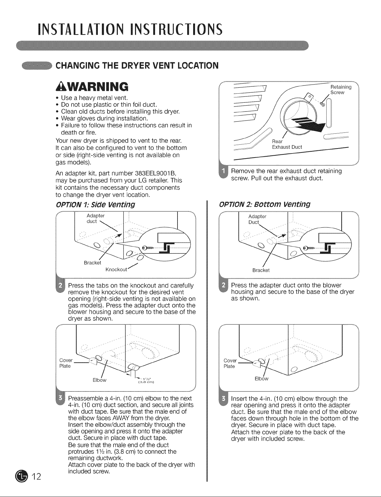
cHANGiNG THE DRYER VENT LOcATiON
, WARN|NG
, Use a heavy metal vent.
• Do not use plastic or thin foil duct.
Clean old ducts before installing this dryer.
Wear gloves during installation.
Failure to follow these instructions can result in
death or fire.
Your new dryer is shipped to vent to the rear.
It can also be configured to vent to the bottom
or side (right-side venting is not available on
gas models).
An adapter kit, part number 383EEL9001B,
may be purchased from your LG retailer. This
kit contains the necessary duct components
to change the dryer vent location.
OPTION 1: Side Venting
Adapter
Retaining
Screw
Rear
Exhaust Duct
Remove the rear exhaust duct retaining
screw. Pull out the exhaust duct.
OPTION 2: BOttOm Venting
Adapter
Duct - .
12
Press the tabs on the knockout and carefully
remove the knockout for the desired vent
opening (right-side venting is not available on
gas models). Press the adapter duct onto the
blower housing and secure to the base of the
dryer as shown.
Cover """-';_
Plate
Elbow
............................................................................................................................................................................................................................................................................................................................................................................................................................_J
(3.8 om)
Preassemble a 4-in. (10 cm) elbow to the next
4-in. (10 cm) duct section, and secure all joints
with duct tape. Be sure that the male end of
the elbow faces AWAY from the dryer.
Insert the elbow/duct assembly through the
side opening and press it onto the adapter
duct. Secure in place with duct tape.
Be sure that the male end of the duct
protrudes 11/2in. (3.8 cm) to connect the
remaining ductwork.
Attach cover plate to the back of the dryer with
included screw.
Bracket
Press the adapter duct onto the blower
housing and secure to the base of the dryer
as shown.
Elbow
insert the 4-in. (10 cm) elbow through the
rear opening and press it onto the adapter
duct. Be sure that the male end of the elbow
faces down through hole in the bottom of the
dryer. Secure in place with duct tape.
Attach the cover plate to the back of the
dryer with included screw.
INSTAllATION INST UcTIONS
VENTING THE DRYER
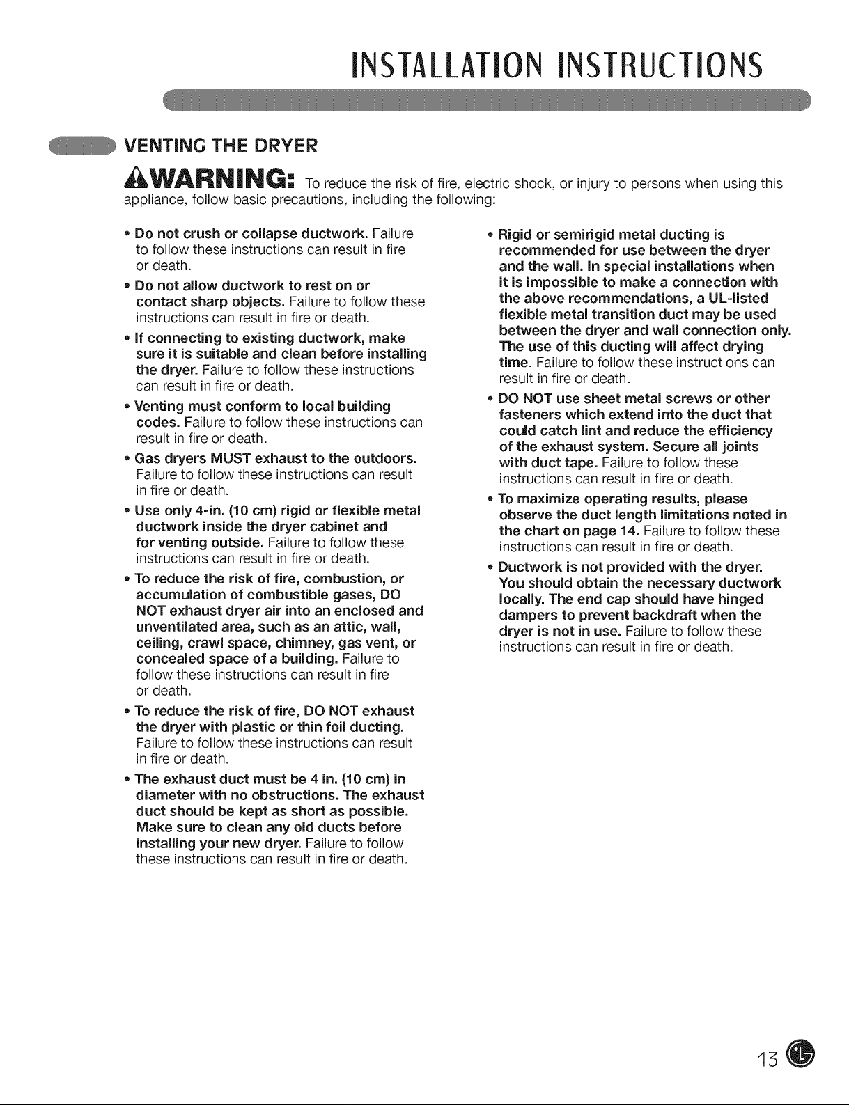
WARN|NG: to reduce the risk of fire, electric shock, or injury to persons when using this
appliance, follow basic precautions, including the following:
• Do not crush or collapse ductwork. Failure
to follow these instructions can result in fire
or death.
• Do not allow ductwork to rest on or
contact sharp objects. Failure to follow these
instructions can result in fire or death.
• If connecting to existing ductwork, make
sure it is suitable and clean before installing
the dryer. Failure to follow these instructions
can result in fire or death.
• Venting must conform to local building
codes. Failure to follow these instructions can
result in fire or death.
Gas dryers MUST exhaust to the outdoors.
Failure to follow these instructions can result
in fire or death.
• Use only 4-in. {10 cm) rigid or flexible metal
ductwork inside the dryer cabinet and
for venting outside. Failure to follow these
instructions can result in fire or death.
• To reduce the risk of fire, combustion, or
accumulation of combustible gases, DO
NOT exhaust dryer air into an enclosed and
unventilated area, such as an attic, wall,
ceiling, crawl space, chimney, gas vent, or
concealed space of a building. Failure to
follow these instructions can result in fire
or death.
• To reduce the risk of fire, DO NOT exhaust
the dryer with plastic or thin foil ducting.
Failure to follow these instructions can result
in fire or death.
• The exhaust duct must be 4 in. 110 cm) in
diameter with no obstructions. The exhaust
duct should be kept as short as possible.
Make sure to clean any old ducts before
installing your new dryer. Failure to follow
these instructions can result in fire or death.
, Rigid or semirigid metal ducting is
recommended for use between the dryer
and the wall. In special installations when
it is impossible to make a connection with
the above recommendations, a UL=listed
flexible metal transition duct may be used
between the dryer and wall connection only.
The use of this ducting will affect drying
time. Failure to follow these instructions can
result in fire or death.
DO NOT use sheet metal screws or other
fasteners which extend into the duct that
could catch lint and reduce the efficiency
of the exhaust system. Secure all joints
with duct tape. Failure to follow these
instructions can result in fire or death.
• To maximize operating results, please
observe the duct length limitations noted in
the chart on page 14. Failure to follow these
instructions can result in fire or death.
• Ductwork is not provided with the dryer.
You should obtain the necessary ductwork
locally. The end cap should have hinged
dampers to prevent backdraft when the
dryer is not in use. Failure to follow these
instructions can result in fire or death.
15
iNSTALLATiONINSTRUCTIONS
VENTING THE DRYER {cont.)
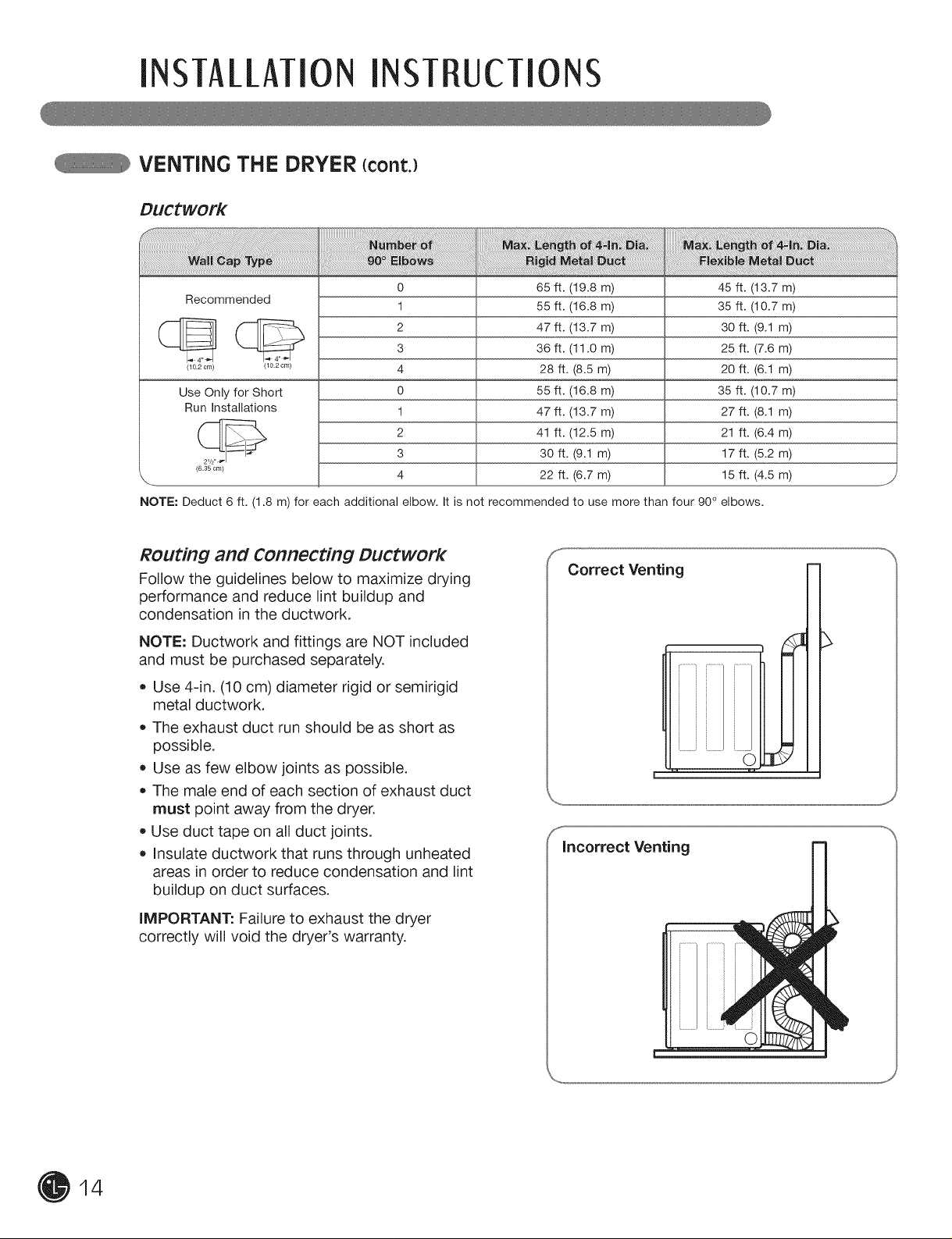
Ductwork
Recommended
(f--]]_'L_ 2 47 ft. (13.7 m) 30 ft. (9.1 m)3 36 ft. (11.0 m) 25 ft. (7.6 m)
(_02om/ (_02om/ 4 28 ft. (8.5 m) 20 ft. (6.1 m)
Use Only for Short 0 55 ft. (16.8 m) 35 ft. (10.7 m)
Run Installations 1 47 ft. (13.7 m) 27 ft. (8.1 m)
---_ 2 41 ft. (12.5 m) 21 ft. (6.4 m)
(63_o,,,/ 4 22 ft. (6.7 m) 15 ft. (4.5 m)
NOTE: Deduct 6 ft. (1.8 m) for each additional elbow. It is not recommended to use more than four 90° elbows.
0 65 ft. (19.8 m) 45 ft. (13.7 m)
1 55 ft. (16.8 m) 35 ft. (10.7 m)
3 30 ft. (9.1 m) 17 ft. (5.2 m)
ROuting and Connecting Ductwork
Follow the guidelines below to maximize drying
performance and reduce lint buildup and
condensation in the ductwork.
NOTE: Ductwork and fittings are NOT included
and must be purchased separately.
• Use 4-in. (10 cm) diameter rigid or semirigid
metal ductwork.
The exhaust duct run should be as short as
possible.
Use as few elbow joints as possible.
The male end of each section of exhaust duct
must point away from the dryer.
Use duct tape on all duct joints.
Insulate ductwork that runs through unheated
areas in order to reduce condensation and lint
buildup on duct surfaces.
Correct Venting
incorrect Venting
0
14
iMPORTANT: Failure to exhaust the dryer
correctly will void the dryer's warranty.
INSTAllATIONINSTRUCTIONS
cONNEcTiNG GASDRYERS
_WAF_N|NG -u To reduce the risk of fire, electric shock, or injury to persons when using this
appliance, follow basic precautions, including the following:
• Gas supply requirements:
As shipped from the factory, this dryer
is configured for use with natural gas.
it can be converted for use with LP
(Liquefied Propane) gas. Gas pressure
must not exceed 13 in. water column.
• A qualified service or gas company
technician must connect the dryer to the
gas service. Failure to do so can result in fire,
explosion, or death.
• Isolate the dryer from the gas supply system
by closing its individual manual shutoff
valve during any pressure testing of the
gas supply. Failure to do so can result in fire,
explosion, or death.
• Supply line requirements:
Your laundry room must have a rigid gas
supply line to your dryer. In the United
States, an individual manual shutoff valve
MUST be installed within at least 6 ft. (1.8 m)
of the dryer, in accordance with the National
Fuel Gas Code ANSI Z223.1. A 1/8=in. NPT
pipe plug must be installed. Failure to do so
can result in fire, explosion, or death.
• if using a rigid pipe, the rigid pipe should be
1/2=in. IPS. if acceptable under local codes
and ordinances and when acceptable to
your gas supplier, 3/8=in. approved tubing
may be used where lengths are less than 20
ft. (6.1 m). Larger tubing should be used for
lengths in excess of 20 ft. (6.1 m). Failure to
do so can result in fire, explosion, or death.
• Connect the dryer to the type of gas shown
on the nameplate. Failure to do so can result
in fire, explosion, or death.
• To prevent contamination of the gas valve,
purge the gas supply of air and sediment
before connecting the gas supply to the
dryer. Before tightening the connection
between the gas supply and the dryer,
purge remaining air until the odor of gas is
detected. Failure to do so can result in fire,
explosion, or death.
• DO NOT use an open flame to inspect
for gas leaks. Use a noncorrosive leak=
detection fluid. Failure to do so can result in
fire, explosion, or death.
• Use only a new AGA= or CSA=certified gas
supply line with flexible stainless steel
connectors. Failure to do so can result in fire,
explosion, or death.
• Securely tighten all gas connections. Failure
to do so can result in fire, explosion, or death.
• Use Teflon ®tape or a pipe-joint compound
that is insoluble in Liquefied Petroleum (LP)
gas on all pipe threads. Failure to do so can
result in fire, explosion, or death.
• DO NOT attempt any disassembly of
the dryer; any disassembly requires the
attention and tools of an authorized and
qualified service person or company. Failure
to do so can result in fire, explosion, or death.
Electrical Requirements for Gas MOdelS Only
WARNING-" To reduce the risk of fire, electric shock, or injury to persons when using this
appliance, follow basic precautions, including the following:
• Do not, under any circumstances, cut or
remove the third (ground) prong from the
power cord. Failure to follow this warning can
result in fire, explosion, or death.
• For personal safety, this dryer must be
properly grounded. Failure to follow this
warning can result in fire, explosion, or death.
• The power cord of this dryer is equipped with
a 3=prong (grounding) plug which mates with
a standard 3=prong (grounding) wall outlet
to minimize the possibility of electric shock
hazard from this appliance. Failure to follow
this warning can result in fire, explosion,
or death.
This dryer must be plugged into a
120=VAC, 60=Hz. grounded outlet protected
by a 15=ampere fuse or circuit breaker.
Failure to follow this warning can result in fire,
explosion, or death.
Where a standard 2=prong wall outlet
is encountered, it is your personal
responsibility and obligation to have it
replaced with a properly grounded 3=prong
wall outlet. Failure to follow this warning can
result in fire, explosion, or death.
15
INSTAllATiON INST UcTIONS
cONNEcTiNG GAS DRYERS (cont.)
WARN|NG:
appliance, follow basic precautions, including the following:
• Installation and service must be performed •
by a qualified installer, service agency, or the
gas supplier.Failure to do so can result in fire,
explosion, or death.
• Use only a new stainless steel flexible
connector and a new AGA=certified
connector. Failure to do so can result in fire,
explosion, or death.
A gas shutoff valve must be installed within
6 ft. (1.8 m) of the dryer. Failure to do so can
result in fire, explosion, or death.
The dryer is configured for Natural Gas when
shipped from the factory. Make sure that the
dryer is equipped with the correct burner
nozzle for the type of gas being used (Natural
Gas or Liquefied Petroleum). Failure to do so
can result in fire, explosion, or death.
To reduce the risk of fire, electric shock, or injury to persons when using this
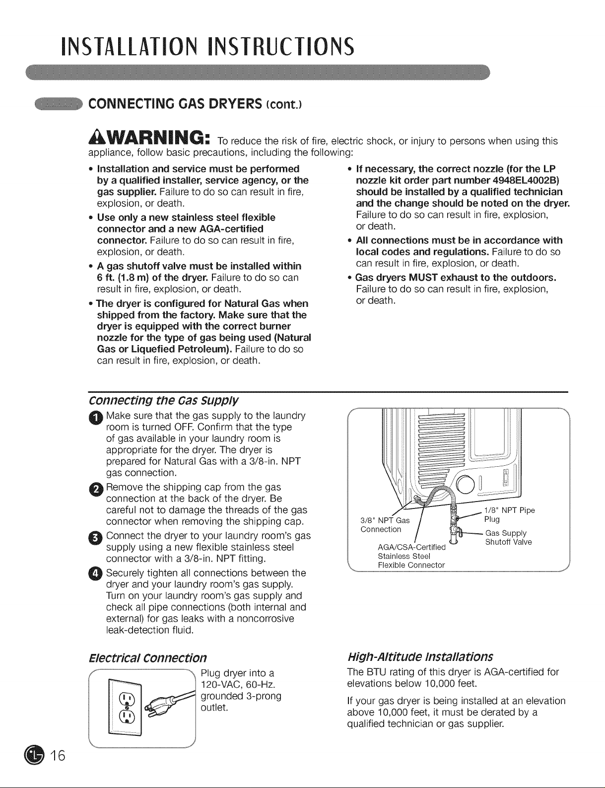
Connecting the Gas Supply
O Make sure that the gas supply to the laundry
room is turned OFR Confirm that the type
of gas available in your laundry room is
appropriate for the dryer. The dryer is
prepared for Natural Gas with a 3/8-in. NPT
gas connection.
O Remove the shipping cap from the gas
connection at the back of the dryer. Be
careful not to damage the threads of the gas
connector when removing the shipping cap.
O Connect the dryer to your laundry room's gas
supply using a new flexible stainless steel
connector with a 3/8-in. NPT fitting.
_! Securely all connections between the
dryer and your laundry room's gas supply.
Turn on your laundry room's gas supply and
check all pipe connections (both internal and
external) for gas leaks with a noncorrosive
leak-detection fluid.
tighten
if necessary, the correct nozzle (for the LP
nozzle kit order part number 4948EL4002B)
should be installed by a qualified technician
and the change should be noted on the dryer.
Failure to do so can result in fire, explosion,
or death.
All connections must be in accordance with
local codes and regulations. Failure to do so
can result in fire, explosion, or death.
Gas dryers MUST exhaust to the outdoors.
Failure to do so can result in fire, explosion,
or death.
3/8" NPT Gas Plug
Connection Supply
AGA/CSA-Certified
Stainless Steel
\_ Flexible Connector
...........................................................................................................................................................................................................................................................................................................................................................................................................................................j_
1/8" NPT Pipe
Shutoff Valve
16
Electrical Connection
Plug dryer into a
120-VAC, 60-Hz.
grounded 3-prong
outlet.
High-Altitude Installations
The BTU rating of this dryer is AGA-certified for
elevations below 10,000 feet.
If your gas dryer is being installed at an elevation
above 10,000 feet, it must be derated by a
qualified technician or gas supplier.

INSTAllATION INSTRUCTIONS
cONNEcTiNG ELEcTRic DRYERS
_WARN|_I_G -= To help prevent fire, electric shock, serious injury, or death, the wiring and
grounding must conform to the latest edition of the National Electrical Code, ANSI/NFPA 70 and all
applicable local regulations. Please contact a qualified electrician to check your home's wiring and
fuses to ensure that your home has adequate electrical power to operate the dryer.
Electrical Requirements for Electric MOdelS Only
AWARNING: To reduce the risk of fire, electric shock, or injury to persons when using this
appliance, follow basic precautions, including the following:
• This dryer must be connected to a grounded
metal, permanent wiring system, or an
equipment=grounding conductor must be run
with the circuit conductors and connected
to the equipment=grounding terminal or lead
on the dryer. Failure to do so can result in fire,
explosion, or death.
, The dryer has its own terminal block that
must be connected to a separate 240 VAC,
60=Hertz, single=phase circuit, fused at 30
amperes (the circuit must be fused on both ,
sides of the line). ELECTRICAL SERVICE
FOR THE DRYER SHOULD BE OF THE
MAXIMUM RATE VOLTAGE LISTED ON THE
NAMEPLATE. DO NOT CONNECT DRYER TO
110=, 115=, OR 120=VOLT CIRCUIT. Heating
elements are available for field installation
in dryers which are to be connected to an
electrical service of a different voltage than
that listed on the rating plate. Failure to follow
these instructions can result in fire, explosion,
or death.
if branch circuit to dryer is 15 ft. (4.5 m)
or less in length, use UL (Underwriters
Laboratories) listed No.=10 AWG wire
(copper wire only), or as required by local
codes. If over 15 ft. (4.50 m), use UL=listed
No.=8 AWG wire (copper wire only), or as
required by local codes. Allow sufficient
slack in wiring so dryer can be moved from
its normal location when necessary. Failure
to do so can result in fire, explosion, or death.
The power cord (pigtail) connection between
wall receptacle and dryer terminal block
IS NOT supplied with dryer. Type of pigtail
and gauge of wire must conform to local
codes and with instructions on the following
pages. Failure to follow these instructions can
result in fire, explosion, or death.
A 4=wire connection is required for all mobile
and manufactured home installations, as
well as all new construction after January
1, 1996. A 4=wire connection must be used
where local codes do not permit grounding
through the neutral wire. Failure to do so can
result in fire, explosion, or death.
Special Electrical Requirements for Mobile or Manufactured Homes
_ILW_ILR_!!_ | NG -" To reduce the risk of fire, electric shock, or injury to persons when using this
appliance, follow basic precautions, including the following:
• Any installation in a manufactured or mobile
home must comply with the Manufactured
Home Construction and Safety Standards
Title 24 CFR, Part 32-80 or Standard CAN/
CSAOZ240 MH and local codes and ordinances.
• A 4-wire connection is required for all mobile
and manufactured home installations, as well
as all new construction after January 1, 1996.
Failure to do so can result in fire, explosion,
or death.
17
INSTAllATiON INST UcTIONS
cONNEcTiNG ELEcTRic DRYERS {cont.)
USA ONLY
WARN|NG:
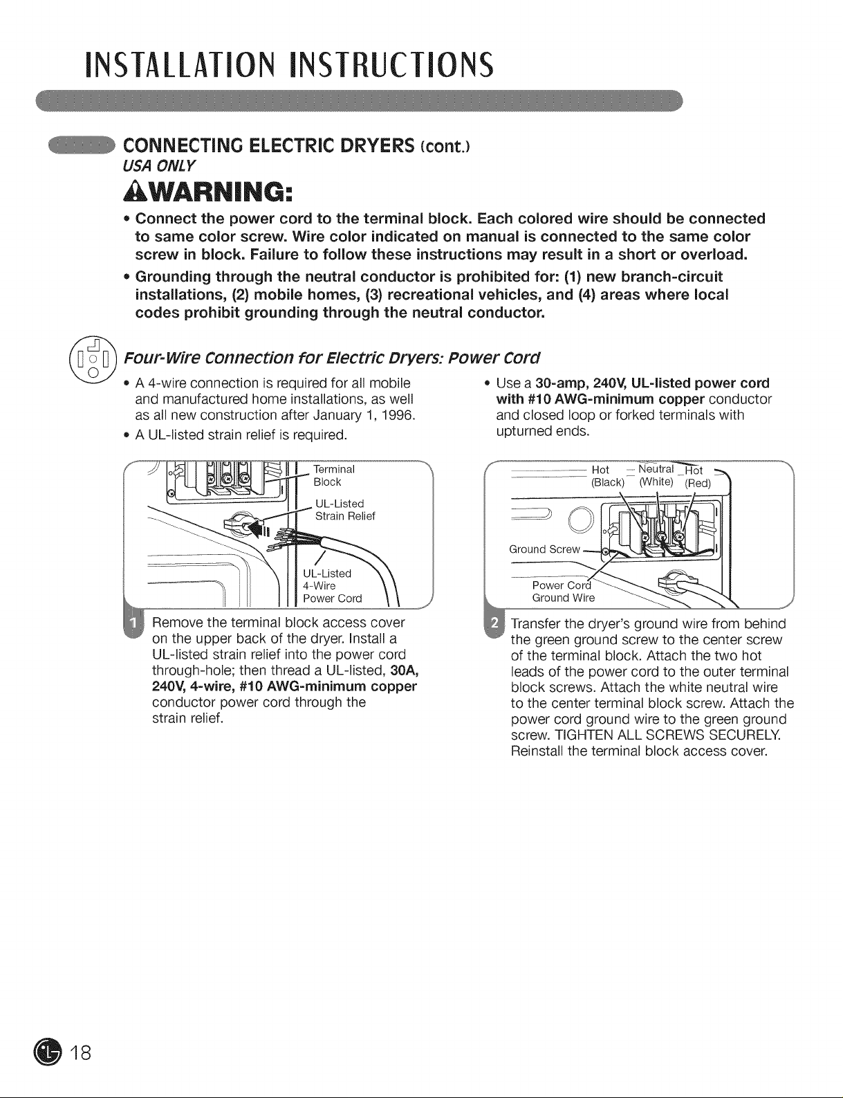
• Connect the power cord to the terminal block. Each colored wire should be connected
to same color screw. Wire color indicated on manual is connected to the same color
screw in block. Failure to follow these instructions may result in a short or overload.
• Grounding through the neutral conductor is prohibited for: (1) new branch-circuit
installations, (2) mobile homes, (3) recreational vehicles, and (4) areas where local
codes prohibit grounding through the neutral conductor.
©
Four-wire Connection for Electric Dryers: Power Cord
• A 4-wire connection is required for all mobile
and manufactured home installations, as well
as all new construction after January 1, 1996.
A UL-listed strain relief is required.
Terminal
Block
UL-Listed
Relief
_' UL-Listed
4-Wire
Power Cord
Remove the terminal block access cover
on the upper back of the dryer. Install a
UL-listed strain relief into the power cord
through-hole; then thread a UL-listed, 30A,
240V, 4-wire, #10 AWG-rninirnurn copper
conductor power cord through the
strain relief.
= Use a 30-arnp, 240V, UL-listed power cord
with #10 AWG=minimum copper conductor
and closed loop or forked terminals with
upturned ends.
GroundScrew _1
Transfer the dryer's ground wire from behind
the green ground screw to the center screw
of the terminal block. Attach the two hot
leads of the power cord to the outer terminal
block screws. Attach the white neutral wire
to the center terminal block screw. Attach the
power cord ground wire to the green ground
screw. TIGHTEN ALL SCREWS SECURELY.
Reinstall the terminal block access cover.
Hot Neutral Hot
(Black)-- (White) (Red)
Ground Wire ,_
18
INSTAllATION INSTRUCTIONS
cONNEcTiNG ELEcTRic DRYERS {cont.)
USA ONLY
WARN|NG:
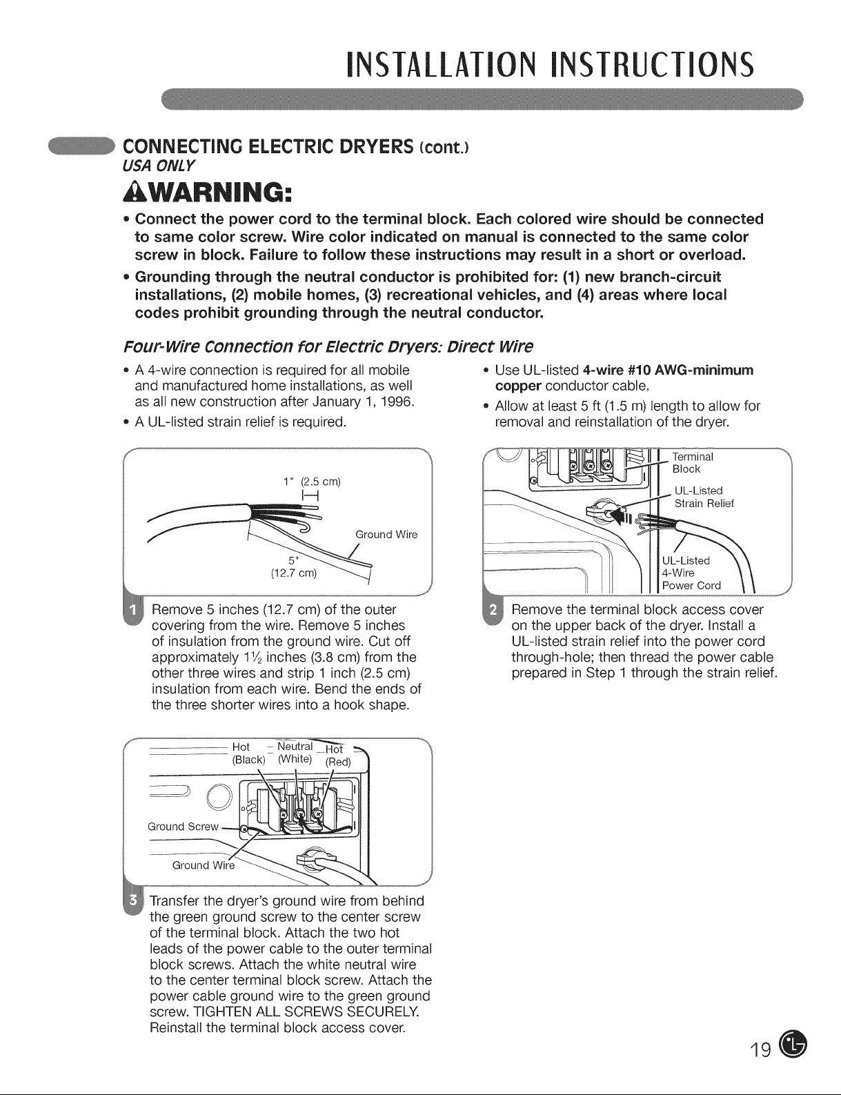
• Connect the power cord to the terminal block. Each colored wire should be connected
to same color screw. Wire color indicated on manual is connected to the same color
screw in block. Failure to follow these instructions may result in a short or overload.
• Grounding through the neutral conductor is prohibited for: (1) new branch-circuit
installations, (2) mobile homes, (3) recreational vehicles, and (4) areas where local
codes prohibit grounding through the neutral conductor.
Four-wire Connection for Electric Dryers: Direct wire
= A 4-wire connection is required for all mobile = Use UL-listed 4-wire #10 AWG-minirnurn
and manufactured home installations, as well copper conductor cable.
as all new construction after January 1, 1996. • Allow at least 5 ft (1.5 m) length to allow for
A UL-listed strain relief is required, removal and reinstallation of the dryer.
Terminal
Block
1" (2.5 cm)
I-4
I UL-Listed
Strain Relief
Ground Wire
5"
(12.7 cm) ./
Remove 5 inches (12.7 cm) of the outer
covering from the wire. Remove 5 inches
of insulation from the ground wire. Cut off
approximately 11/2inches (3.8 cm) from the
other three wires and strip 1 inch (2.5 cm)
insulation from each wire. Bend the ends of
the three shorter wires into a hook shape.
Hot N_
...............................(Black) (White)
Ground
Ground Wire
Transfer the dryer's ground wire from behind
the green ground screw to the center screw
of the terminal block. Attach the two hot
leads of the power cable to the outer terminal
block screws. Attach the white neutral wire
to the center terminal block screw. Attach the
power cable ground wire to the green ground
screw. TIGHTEN ALL SCREWS SECURELY.
Reinstall the terminal block access cover.
UL-Listed
4-Wire
Power Cord
Remove the terminal block access cover
on the upper back of the dryer. Install a
UL-listed strain relief into the power cord
through-hole; then thread the power cable
prepared in Step 1 through the strain relief.
19
INSTA//MiON INST UcTIONS
cONNEcTiNG ELEcTRic DRYERS {cont.)
USA ONLY
WARN|NG:
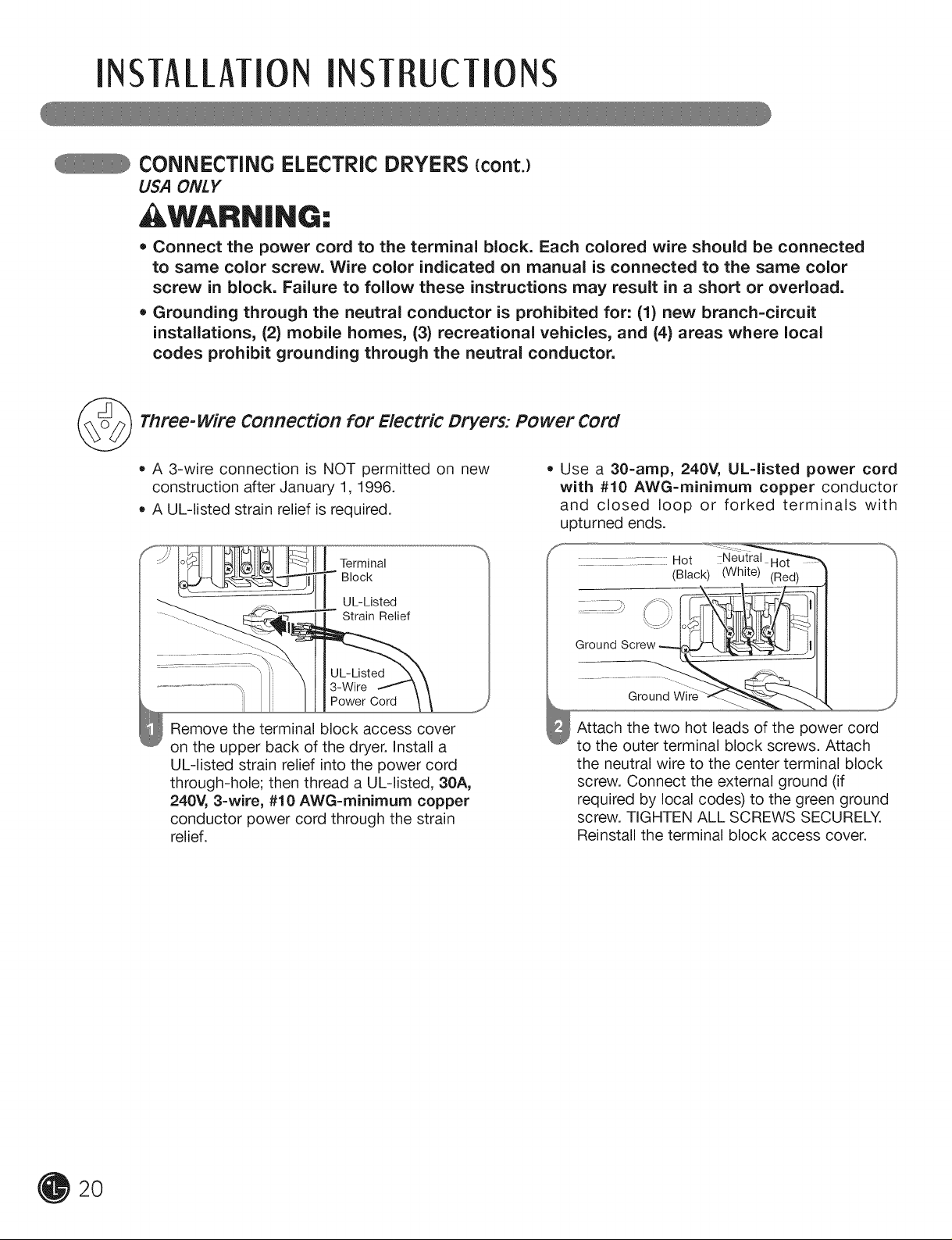
• Connect the power cord to the terminal block. Each colored wire should be connected
to same color screw. Wire color indicated on manual is connected to the same color
screw in block. Failure to follow these instructions may result in a short or overload.
• Grounding through the neutral conductor is prohibited for: (1) new branch-circuit
installations, (2) mobile homes, (3) recreational vehicles, and (4) areas where local
codes prohibit grounding through the neutral conductor.
@
Three-wire Connection for Electric Dryers: Power Cord
• A 3-wire connection is NOT permitted on new
construction after January 1, 1996.
A UL-listed strain relief is required.
Terminal
Block
UL-Listed
Strain Relief
3-Wire
Power Cord
Remove the terminal block access cover
on the upper back of the dryer. Install a
UL-listed strain relief into the power cord
through-hole; then thread a UL-listed, 30A,
240V, 3-wire, #10 AWG-rninirnurn copper
conductor power cord through the strain
relief.
= Use a 30-amp, 240V, UL-listed power cord
with #10 AWG-rninirnurn copper conductor
and closed loop or forked terminals with
upturned ends.
.............. ...... Hot Neutral
Ground
Attach the two hot leads of the power cord
to the outer terminal block screws. Attach
the neutral wire to the center terminal block
screw. Connect the external ground (if
required by local codes) to the green ground
screw. TIGHTEN ALL SCREWS SECURELY.
Reinstall the terminal block access cover.
(Black) (White) (Red)
2O
INSTALLATIONINSTRUCTIONS
CONNECTING ELECTRIC DRYERS {cont.)
USA ONLY
WARN|NG:
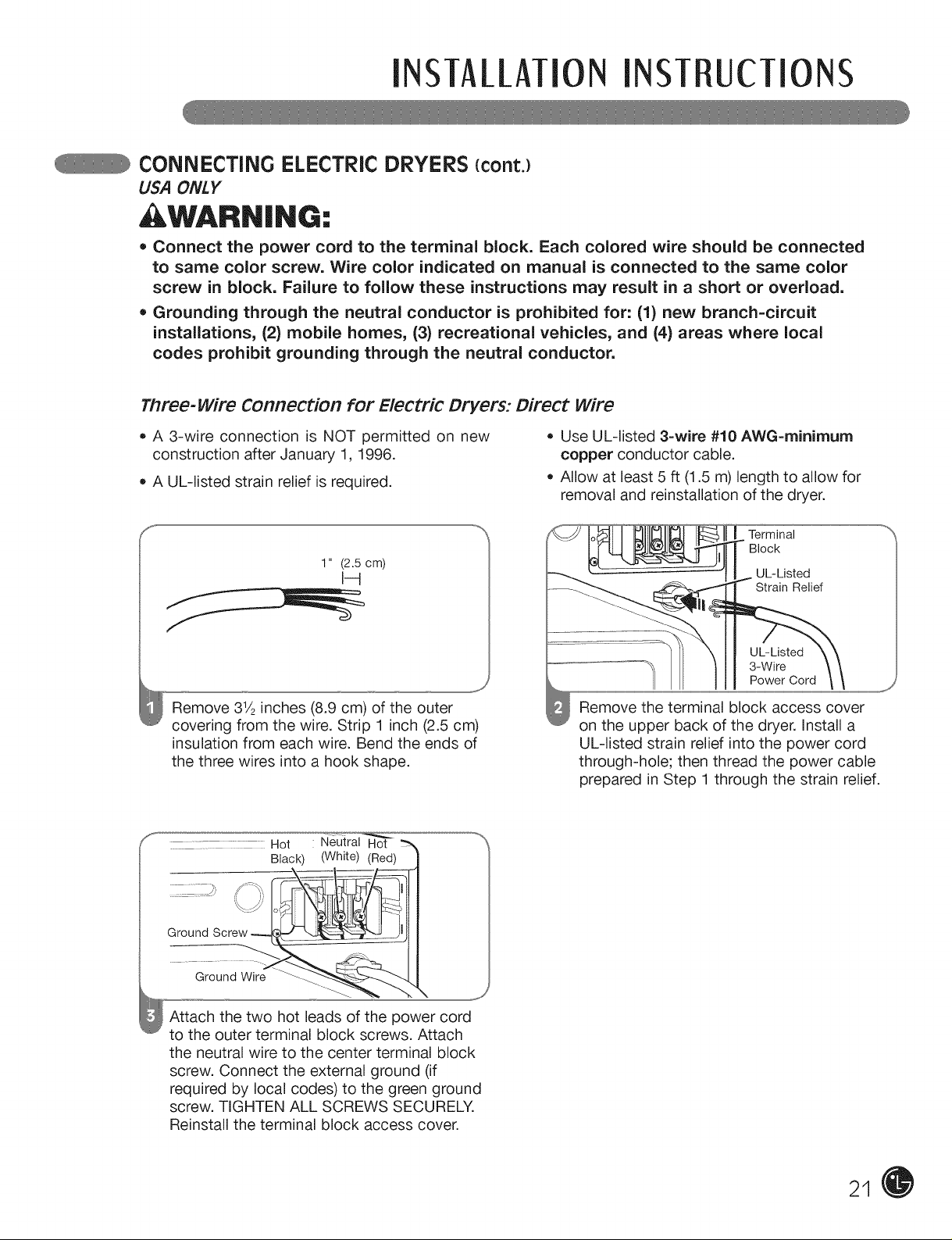
• Connect the power cord to the terminal block. Each colored wire should be connected
to same color screw. Wire color indicated on manual is connected to the same color
screw in block. Failure to follow these instructions may result in a short or overload.
• Grounding through the neutral conductor is prohibited for: (1) new branch-circuit
installations, (2) mobile homes, (3) recreational vehicles, and (4) areas where local
codes prohibit grounding through the neutral conductor.
Three-wire Connection for Electric Dryers: Direct wire
= A 3-wire connection is NOT permitted on new = Use UL-listed 3-wire #10 AWG=minirnurn
construction after January 1, 1996. copper conductor cable.
= A UL-listed strain relief is required. = Allow at least 5 ft (1.5 m) length to allow for
removal and reinstallation of the dryer.
1" (2.5 cm)
I-4
Remove 31/2inches (8.9 cm) of the outer
covering from the wire. Strip 1 inch (2.5 cm)
insulation from each wire. Bend the ends of
the three wires into a hook shape.
....... ..... .....Hot Neutral Hot
Black) (White) (Red)
Ground
Ground Wire
Attach the two hot leads of the power cord
to the outer terminal block screws. Attach
the neutral wire to the center terminal block
screw. Connect the external ground (if
required by local codes) to the green ground
screw. TIGHTEN ALL SCREWS SECURELY.
Reinstall the terminal block access cover.
Terminal
Block
UL-Listed
Strain Relief
UL-Listed
Power Cord
J
3-Wire
Remove the terminal block access cover
on the upper back of the dryer. Install a
UL-listed strain relief into the power cord
through-hole; then thread the power cable
prepared in Step 1 through the strain relief.
j_
21
iNSTALLATiONINST UcTIONS
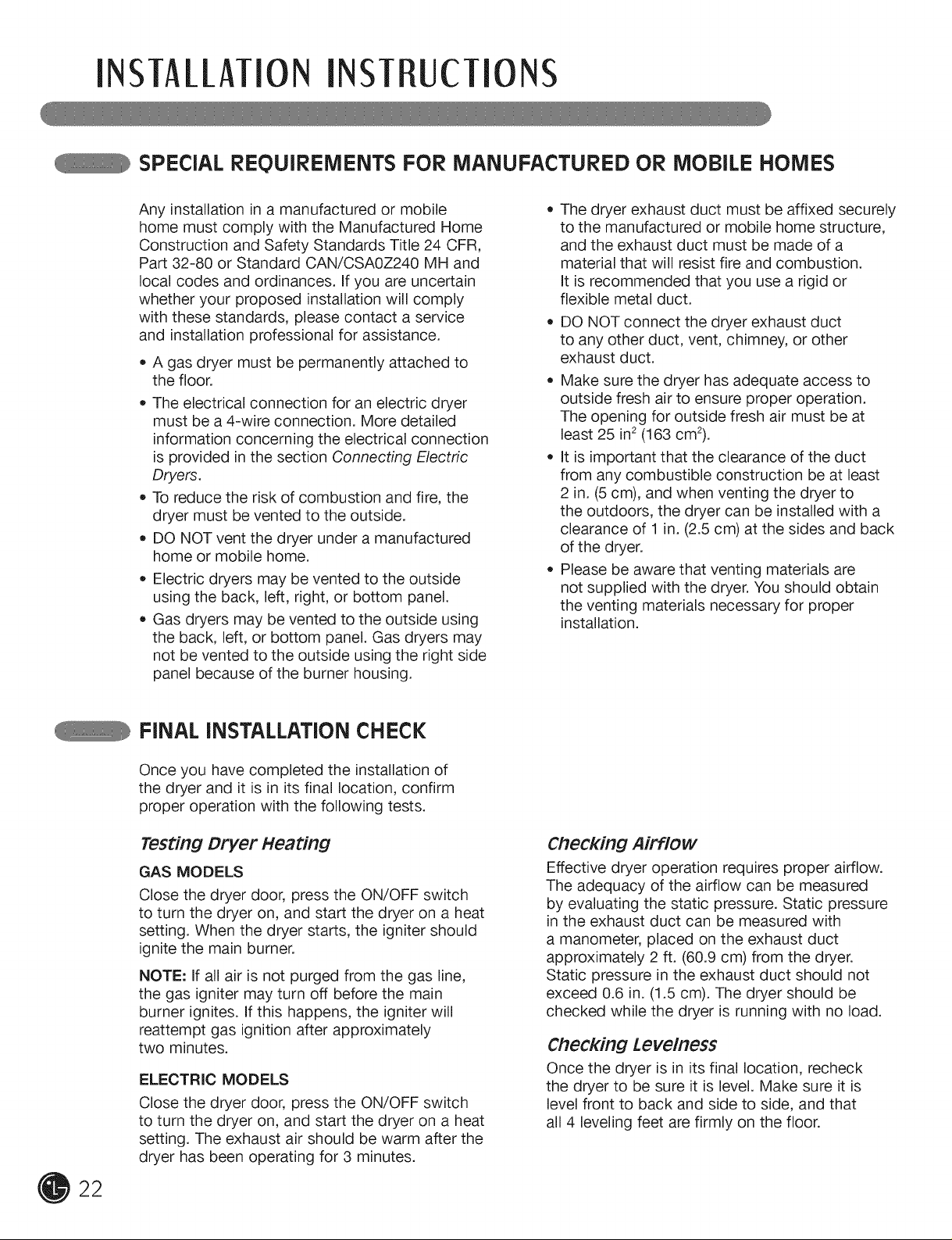
SPEciAL REQUIREMENTS FOR MANUFACTURED OR MOBILE HOMES
Any installation in a manufactured or mobile
home must comply with the Manufactured Home
Construction and Safety Standards Title 24 CFR,
Part 32-80 or Standard CAN/CSAOZ240 MH and
local codes and ordinances. If you are uncertain
whether your proposed installation will comply
with these standards, please contact a service
and installation professional for assistance.
• A gas dryer must be permanently attached to
the floor.
The electrical connection for an electric dryer
must be a 4-wire connection. More detailed
information concerning the electrical connection
is provided in the section Connecting Electric
Dryers.
To reduce the risk of combustion and fire, the
dryer must be vented to the outside.
DO NOT vent the dryer under a manufactured
home or mobile home.
Electric dryers may be vented to the outside
using the back, left, right, or bottom panel.
Gas dryers may be vented to the outside using
the back, left, or bottom panel. Gas dryers may
not be vented to the outside using the right side
panel because of the burner housing.
The dryer exhaust duct must be affixed securely
to the manufactured or mobile home structure,
and the exhaust duct must be made of a
material that will resist fire and combustion.
It is recommended that you use a rigid or
flexible metal duct.
DO NOT connect the dryer exhaust duct
to any other duct, vent, chimney, or other
exhaust duct.
Make sure the dryer has adequate access to
outside fresh air to ensure proper operation.
The opening for outside fresh air must be at
least 25 in2(163 cm2).
It is important that the clearance of the duct
from any combustible construction be at least
2 in. (5 cm), and when venting the dryer to
the outdoors, the dryer can be installed with a
clearance of 1 in. (2.5 cm) at the sides and back
of the dryer.
Please be aware that venting materials are
not supplied with the dryer. You should obtain
the venting materials necessary for proper
installation.
FINAL INSTALLATION CHECK
Once you have completed the installation of
the dryer and it is in its final location, confirm
proper operation with the following tests.
Testing Dryer Heating
GAS MODELS
Close the dryer door, press the ON/OFF switch
to turn the dryer on, and start the dryer on a heat
setting. When the dryer starts, the igniter should
ignite the main burner.
NOTE: If all air is not purged from the gas line,
the gas igniter may turn off before the main
burner ignites. If this happens, the igniter will
reattempt gas ignition after approximately
two minutes.
ELECTRIC MODELS
Close the dryer door, press the ON/OFF switch
to turn the dryer on, and start the dryer on a heat
setting. The exhaust air should be warm after the
dryer has been operating for 3 minutes.
Checking Airflow
Effective dryer operation requires proper airflow.
The adequacy of the airflow can be measured
by evaluating the static pressure. Static pressure
in the exhaust duct can be measured with
a manometer, placed on the exhaust duct
approximately 2 ft. (60.9 cm) from the dryer.
Static pressure in the exhaust duct should not
exceed 0.6 in. (1.5 cm). The dryer should be
checked while the dryer is running with no load.
Checking Levelness
Once the dryer is in its final location, recheck
the dryer to be sure it is level. Make sure it is
level front to back and side to side, and that
all 4 leveling feet are firmly on the floor.
22
flow TO USE
Following are instructions for starting and using your new dryer. Please refer to specific sections of this
manual for more detailed information. Important warning: To reduce the risk of fire, electric shock,
or injury to persons, read this entire manual, including the important Safety instructions, before
operating this dryer.
SORTING LOADS
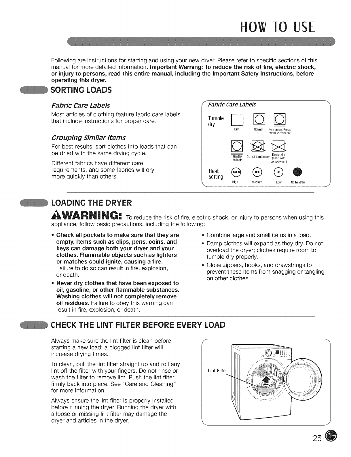
FaDri¢ Care Labels
Most articles of clothing feature fabric care labels
that include instructions for proper care.
....Fabric Care Labels
dry
Dry Normal Permanent Press/
wrinkle resistant
Grouping Similar Items
For best results, sort clothes into loads that can
be dried with the same drying cycle.
Different fabrics have different care
requirements, and some fabrics will dry
more quickly than others.
Gentle/ Do not tumble dry (used with
delicate do not wash)
Heat e @ @O
setting
High Medium Low Noheat/air
Donot dry
LOADING THE DRYER
WARNING" To reduce the risk of fire, electric shock, or injury to persons when using this
appliance, follow basic precautions, including the following:
• Check all pockets to make sure that they are
empty, items such as clips, pens, coins, and
keys can damage both your dryer and your
clothes. Flammable objects such as lighters
or matches could ignite, causing a fire.
Failure to do so can result in fire, explosion,
or death.
• Never dry clothes that have been exposed to
oil, gasoline, or other flammable substances.
Washing clothes will not completely remove
oil residues. Failure to obey this warning can
result in fire, explosion, or death.
Combine large and small items in a load.
Damp clothes will expand as they dry. Do not
overload the dryer; clothes require room to
tumble dry properly.
Close zippers, hooks, and drawstrings to
prevent these items from snagging or tangling
on other clothes.
CHECK THE LINT FILTER BEFORE EVERY LOAD
Always make sure the lint filter is clean before
starting a new load; a clogged lint filter will
increase drying times.
To clean, pull the lint filter straight up and roll any
lint off the filter with your fingers. Do not rinse or
wash the filter to remove lint Push the lint filter
firmly back into place. See "Care and Cleaning"
for more information.
Always ensure the lint filter is properly installed
before running the dryer. Running the dryer with
a loose or missing lint filter may damage the
dryer and articles in the dryer.
Lint Filter
25
OWTO USE
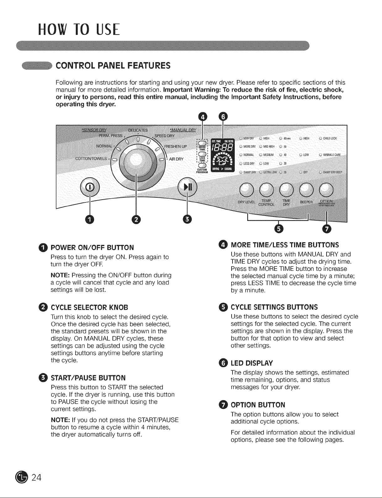
CONTROL PANEL FEATURES
Following are instructions for starting and using your new dryer. Please refer to specific sections of this
manual for more detailed information, important warning: To reduce the risk of fire, electric shock,
or injury to persons, read this entire manual, including the important safety instructions, before
operating this dryer.
POWER ON/OFF BUTTON
O
Press to turn the dryer ON. Press again to
turn the dryer OFR
NOTE: Pressing the ON/OFF button during
a cycle will cancel that cycle and any load
settings will be lost.
CYCLE SELECTOR KNOB
O
Turn this knob to select the desired cycle.
Once the desired cycle has been selected,
the standard presets will be shown in the
display. On MANUAL DRY cycles, these
settings can be adjusted using the cycle
settings buttons anytime before starting
the cycle.
START/PAUSE BUTTON
O
Press this button to START the selected
cycle. If the dryer is running, use this button
to PAUSE the cycle without losing the
current settings.
NOTE: If you do not press the START/PAUSE
button to resume a cycle within 4 minutes,
the dryer automatically turns off.
MORE TIME/LESS TIME BUTTONS
O
Use these buttons with MANUAL DRY and
TIME DRY cycles to adjust the drying time.
Press the MORE TIME button to increase
the selected manual cycle time by a minute;
press LESS TIME to decrease the cycle time
by a minute.
CYCLE SETTINGS BUTTONS
O
Use these buttons to select the desired cycle
settings for the selected cycle. The current
settings are shown in the display. Press the
button for that option to view and select
other settings.
LED DISPLAY
O
The display shows the settings, estimated
time remaining, options, and status
messages for your dryer.
OPTION BUTTON
O
The option buttons allow you to select
additional cycle options.
For detailed information about the individual
options, please see the following pages.
24
0 TO USE
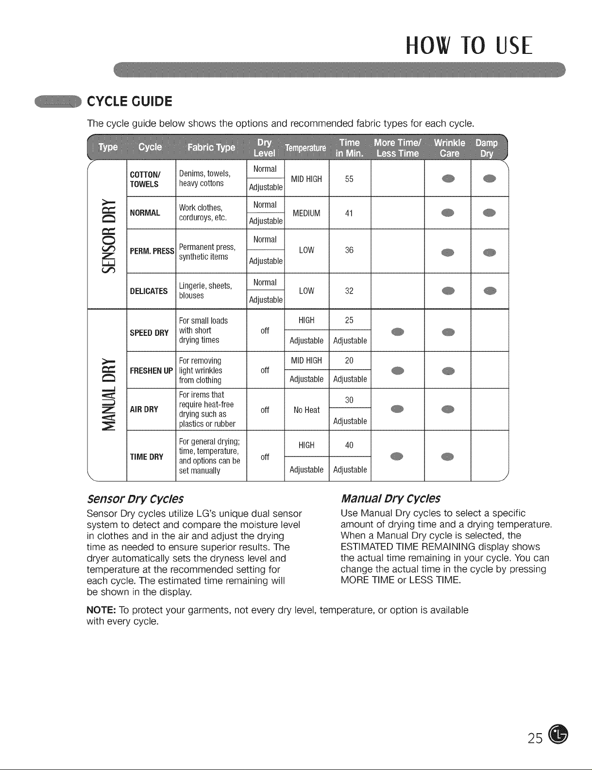
CYCLE GUIDE
The cycle guide below shows the options and recommended fabric types for each cycle.
OOTTON/ Denims,towels,
Normal
TOWELS heavycottons Adjustable
NORMAL
PERM.PRESS
DELICATES
JSPEEDDRY
FRESHENUP
AiR DRY
TiME DRY
Workclothes, Normal
corduroys,etc. Adjustable
Normal
Permanentpress, LOW 36 _
syntheticitems Adjustable
Lingerie,sheets, Normal
blouses
Forsmallloads HiGH 25
with short off
dryingtimes Adjustable Adjustable
Forremoving MIDHIGH 20
lightwrinkles off
from clothing Adjustable Adjustable
Foritemsthat
requireheat-free off No Heat
dryingsuchas
plasticsor rubber Adjustable
Forgeneraldrying; HIGH 40
time,temperature,
andoptions canbe off
setmanually Adjustable Adjustable
Adjustable
MIDHIGH 55 _
MEDIUM 41 _
LOW 32 _
30
J
Sensor Dr}" Cycles
Sensor Dry cycles utilize LG's unique dual sensor
system to detect and compare the moisture level
in clothes and in the air and adjust the drying
time as needed to ensure superior results. The
dryer automatically sets the dryness level and
temperature at the recommended setting for
each cycle. The estimated time remaining will
Manual Dry Cycles
Use Manual Dry cycles to select a specific
amount of drying time and a drying temperature.
When a Manual Dry cycle is selected, the
ESTIMATED TIME REMAINING display shows
the actual time remaining in your cycle. You can
change the actual time in the cycle by pressing
MORE TIME or LESS TIME.
be shown in the display.
NOTE: To protect your garments, not every dry level, temperature, or option is available
with every cycle.
25
OWTO USE
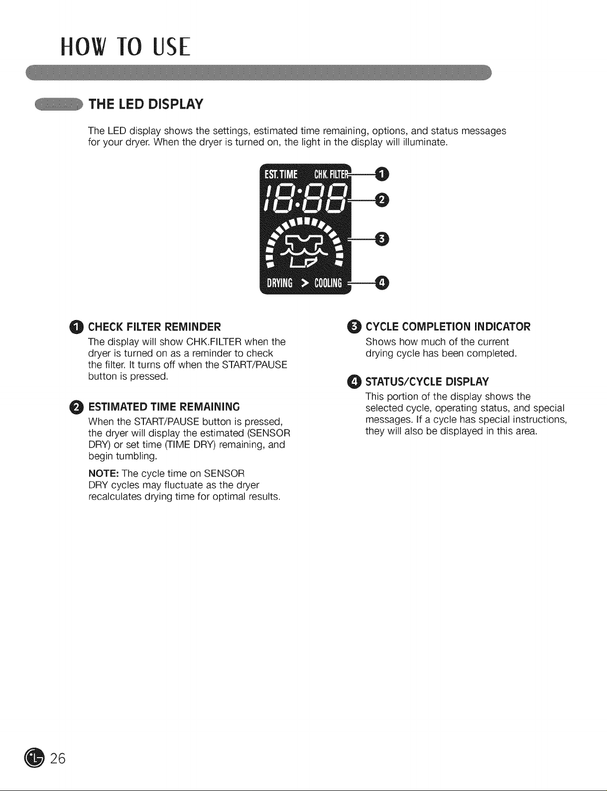
THE LED DISPLAY
The LED display shows the settings, estimated time remaining, options, and status messages
for your dryer. When the dryer is turned on, the light in the display will illuminate.
CHECK FILTER REMINDER
O
The display will show CHK.FILTER when the
dryer is turned on as a reminder to check
the filter. It turns off when the START/PAUSE
button is pressed.
ESTIMATED TiME REMAiNiNG
O
When the START/PAUSE button is pressed,
the dryer will display the estimated (SENSOR
DRY) or set time (TIME DRY) remaining, and
begin tumbling.
NOTE: The cycle time on SENSOR
DRY cycles may fluctuate as the dryer
recalculates drying time for optimal results.
CYCLE COMPLETION iNDiCATOR
Shows how much of the current
drying cycle has been completed.
_) STATUS/CYCLE DISPLAY
This portion of the display shows the
selected cycle, operating status, and special
messages. If a cycle has special instructions,
they will also be displayed in this area.
26
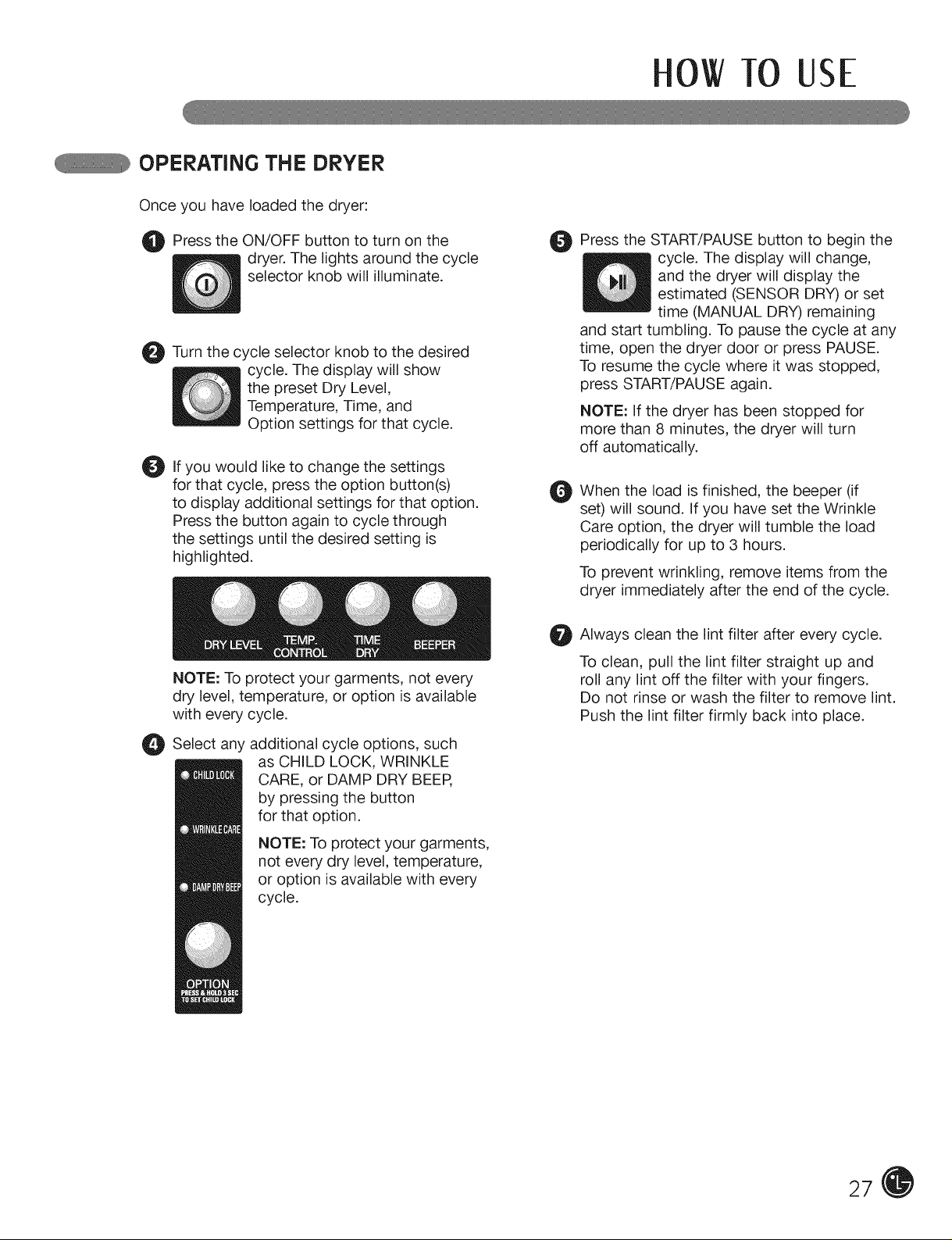
OPERATING THE DRYER
Once you have loaded the dryer:
0 TO USE
O Press the ON/OFF button to turn the
dryer. The lights around the cycle
selector knob will illuminate.
_t Turn the selector knob to the desired
Oil you to change settings
for that cycle, press the option button(s)
to display additional settings for that option.
Press the button again to cycle through
the settings until the desired setting is
highlighted.
NOTE: To protect your garments, not every
dry level, temperature, or option is available
with every cycle.
Select any additional cycle options,
cycle
cycle. The display will show
the preset Dry Level,
Temperature, Time, and
Option settings for that cycle.
would like the
as CHILD LOCK, WRINKLE
CARE, or DAMP DRY BEEP,
by pressing the button
for that option.
NOTE: To protect your garments,
not every dry level, temperature,
or option is available with every
cycle.
on
such
O Press the START/PAUSE button to begin the
cycle. The display will change,
and the dryer will display the
estimated (SENSOR DRY) or set
time (MANUAL DRY) remaining
and start tumbling. To pause the cycle at any
time, open the dryer door or press PAUSE.
To resume the cycle where it was stopped,
press START/PAUSE again.
NOTE: If the dryer has been stopped for
more than 8 minutes, the dryer will turn
off automatically.
When the load is finished, the beeper (if
O
set) will sound. If you have set the Wrinkle
Care option, the dryer will tumble the load
periodically for up to 3 hours.
To prevent wrinkling, remove items from the
dryer immediately after the end of the cycle.
Always clean the lint filter after every cycle.
O
To clean, pull the lint filter straight up and
roll any lint off the filter with your fingers.
Do not rinse or wash the filter to remove lint.
Push the lint filter firmly back into place.
27
OWTO USE
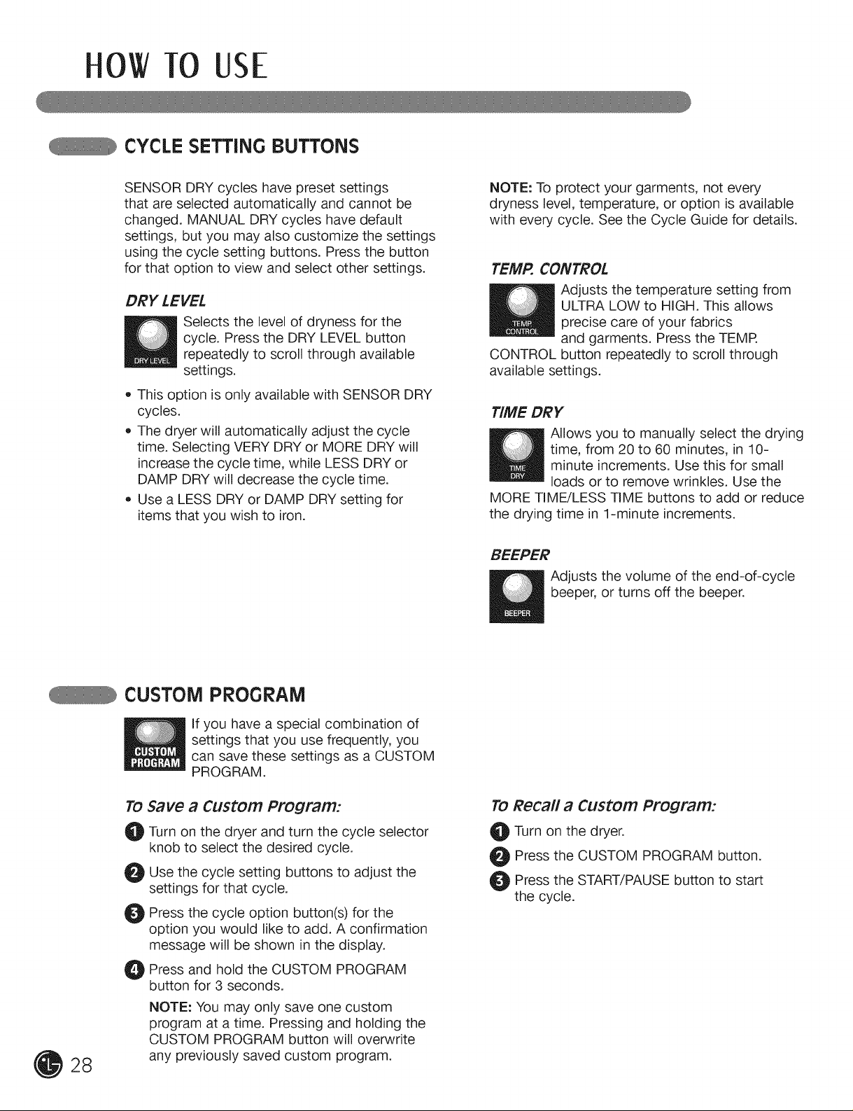
CYCLE SETTING BUTTONS
SENSOR DRY cycles have preset settings
that are selected automatically and cannot be
changed. MANUAL DRY cycles have default
settings, but you may also customize the settings
using the cycle setting buttons. Press the button
for that option to view and select other settings.
DRY LEVEL
Selects the level of dryness for the
cycle. Press the DRY LEVEL button
repeatedly to scroll through available
settings.
• This option is only available with SENSOR DRY
cycles.
The dryer will automatically adjust the cycle
time. Selecting VERY DRY or MORE DRY will
increase the cycle time, while LESS DRY or
DAMP DRY will decrease the cycle time.
Use a LESS DRY or DAMP DRY setting for
items that you wish to iron.
NOTE: To protect your garments, not every
dryness level, temperature, or option is available
with every cycle. See the Cycle Guide for details.
TEMP. CONTROL
Adjusts the temperature setting from
ULTRA LOW to HIGH. This allows
precise care of your fabrics
and garments. Press the TEMR
CONTROL button repeatedly to scroll through
available settings.
TIME DRY
Allows you to manually select the drying
time, from 20 to 60 minutes, in 10-
minute increments. Use this for small
loads or to remove wrinkles. Use the
MORE TIME/LESS TIME buttons to add or reduce
the drying time in 1-minute increments.
BEEPER
Adjusts the volume of the end-of-cycle
beeper, or turns off the beeper.
28
CUSTOM PROGRAM
If you have a special combination of
settings that you use frequently, you
can save these settings as a CUSTOM
PROGRAM.
TO Save El Custom Program:
_! Turn on the dryer and turn the cycle selector
knob to select the desired cycle.
Use the cycle setting buttons to adjust the
settings for that cycle.
Press the cycle option button(s) for the
option you would like to add. A confirmation
message will be shown in the display.
O Press and hold the CUSTOM PROGRAM
button for 3 seconds.
NOTE: You may only save one custom
program at a time. Pressing and holding the
CUSTOM PROGRAM button will overwrite
any previously saved custom program.
TO Recall a Custom Program:
O Turn on the dryer.
O Press the CUSTOM PROGRAM button.
t_ Press the START/PAUSE button to start
the cycle.
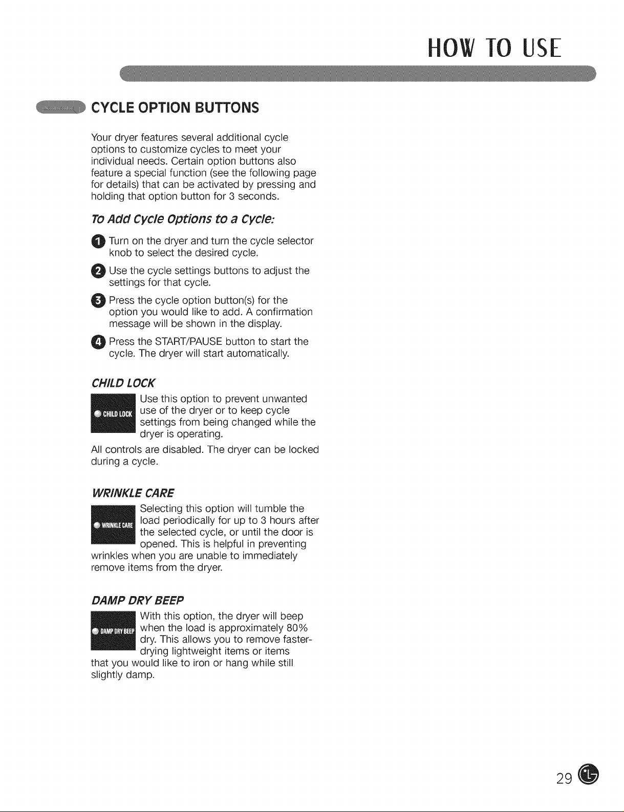
CYCLE OPTION BUTTONS
Your dryer features several additional cycle
options to customize cycles to meet your
individual needs. Certain option buttons also
feature a special function (see the following page
for details) that can be activated by pressing and
holding that option button for 3 seconds.
TO
Add Cycle Options to a Cycle:
Turn on the dryer and turn the cycle selector
0
knob to select the desired cycle.
Use the cycle settings buttons to adjust the
O
settings for that cycle.
Press the cycle option button(s) for the
0
option you would like to add. A confirmation
message will be shown in the display.
O Press the START/PAUSE button to start the
cycle. The dryer will start automatically.
0 TO USE
CHILD LOCK
Use this option to prevent unwanted
settings from being changed while the
use of the dryer or to keep cycle
dryer is operating.
All controls are disabled. The dryer can be locked
during a cycle.
WRINKLE CARE
load periodically for up to 3 hours after
_ electing this option will tumble the
wrinkles when you are unable to immediately
remove items from the dryer.
DAMP DRY BEEP
that you would like to iron or hang while still
slightly damp.
the selected cycle, or until the door is
opened. This is helpful in preventing
when the load is approximately 80%
With this option, the dryer will beep
dry. This allows you to remove faster-
drying lightweight items or items
29
USER- AINTENANcEINSTRUCTIONS
REGULAR CLEANING
_WAF_lii_ | _li_G == To reduce the risk of fire, electric shock, or injury to persons when using this
appliance, follow basic precautions, including the following:
• Unplug the dryer before cleaning to avoid the risk of electric shock. Failure to follow this warning can
cause serious injury, fire, electrical shock, or death.
• Never use harsh chemicals, abrasive cleaners, or solvents to clean the washer.
They will damage the finish.
Cleaning the Exterior
Proper care of your dryer can extend its life.
The outside of the machine can be cleaned with
warm water and a mild, nonabrasive household
detergent.
Immediately wipe off any spills with a soft,
damp cloth.
iMPORTANT: Do not use methylated spirits,
solvents, or similar products.
Never use steel wool or abrasive cleansers; they
can damage the surface.
Cleaning the Interior
Wipe around the door opening and seal with a
soft, damp cloth to prevent lint and dust buildup
that could damage the door seal.
Clean the window with a soft cloth dampened
with warm water and a mild, nonabrasive
household detergent; then wipe dry.
The stainless steel drum can be cleaned with
a conventional stainless steel cleaner, used
according to the manufacturer's specifications.
Never use steel wool or abrasive cleansers; they
can scratch or damage the surface.
Cleaning Around and Under the Dryer
Vacuum lint and dust from around the dryer and
underneath it regularly. Vent ductwork should be
checked for lint buildup and cleaned at least once
per year. If any noticeable reduction in airflow or
drying performance occurs, immediately check
ductwork for obstructions and blockages.
Maintaining Ductwork
Vent ductwork should be checked for lint
buildup and cleaned at least once per year. If
any noticeable reduction in airflow or drying
performance occurs, immediately check ductwork
for obstructions and blockages. Contact a
qualified technician or service provider.
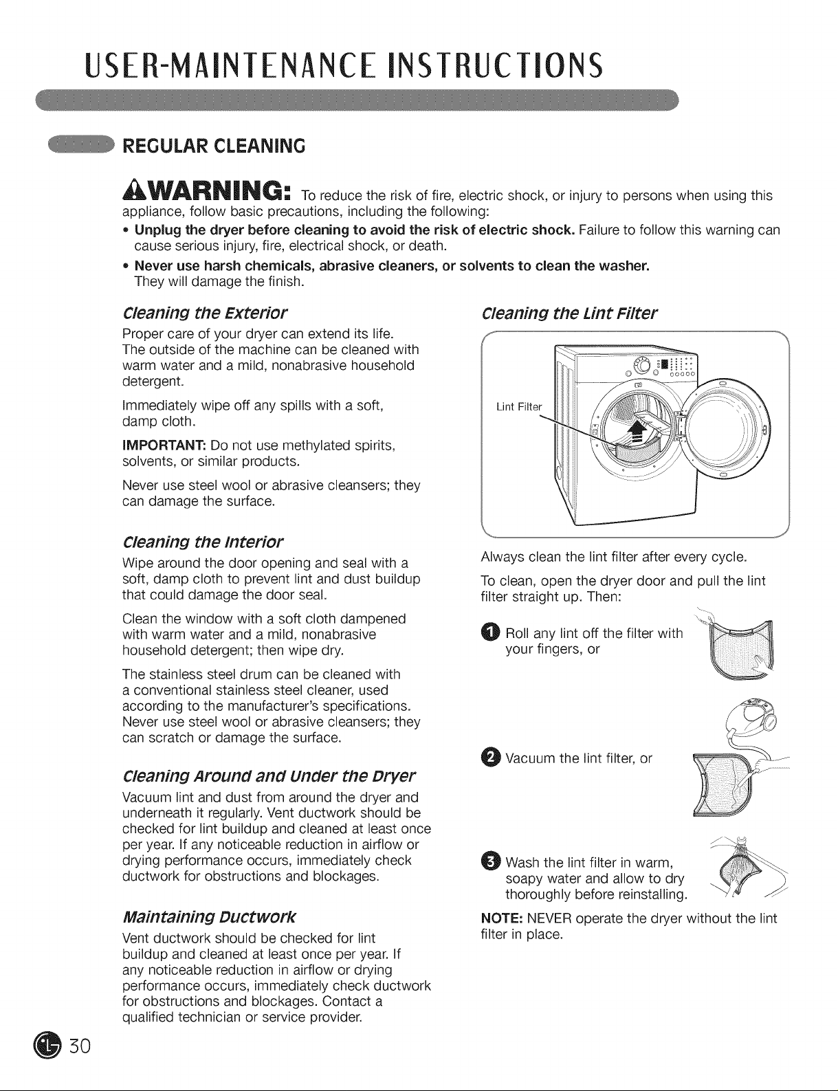
Cleaning the Lint Filter
Lint Filter
Always clean the lint filter after every cycle.
To clean, open the dryer door and pull the lint
filter straight up. Then:
_!) Roll any lint off the filter with
your fingers, or
_1 Vacuum the lint filter, or
_1 Wash the lint filter in warm,
soapy water and allow to dry
thoroughly before reinstalling.
NOTE: NEVER operate the dryer without the lint
filter in place.
5O
 Loading...