

LG DLEX2550 Series, DLEX2450 Series, DLEX2650 Series, DLGX2551 Series, DLGX2451 Series Owner's Manual
...
Life's Good
Please read this manual carefully before operating
your dryer and retain it for future reference.
DLEX2550 _
DLEX2450 _
DLEX2650 _
DLGX2551 _
DLGX2451 _
DLGX2651 _
P/No. MFL67408111
IN] ODUC]-ION
IMPORTANT SAFETY INSTRUCTIONS
What to Do if You Smell Gas .................................. 3
Basic Safety Precautions ....................................... 4
California Safe Drinking Water and Toxic
Enforcement Act ................................................... 4
Grounding Instructions ........................................... 5
Safety Instructions for Installation .......................... 5
Safety Instructions for Steam Functions ................ 6
Safety Instructions for Connecting Electricity ....... 7
PARTSAND FEATURES
Special Features ..................................................... 8
Key Parts and Components ................................... 9
INSTALLATION INSTRUCTIONS
Installation Location Requirements ..................... 10
Clearances ........................................................... 10
Installation With Optional
Pedestal Base or Stacking Kit .............................. 11
Leveling the Dryer ................................................ 12
Optional Accessories .......................................... 12
To Remove the Door ............................................ 13
To Install the Door ............................................... 14
Changing the Dryer Vent Location ....................... 15
Venting the Dryer .................................................. 16
Connecting Gas Dryers ........................................ 18
Connecting Electric Dryers .................................. 20
Special Requirements for Manufactured
or Mobile Homes ................................................. 25
Final Installation Check ....................................... 25
Installation Test (Exhaust check) ......................... 26
HOW TO USE
Control Panel Features ........................................ 28
Operating the Dryer ............................................. 29
Cycle Guide ......................................................... 30
Sorting Loads ...................................................... 31
Loading the Dryer ................................................ 31
Check the Lint Filter Before Every Load .............. 31
The Display .......................................................... 32
Cycle Setting Buttons .......................................... 33
Special Functions ................................................ 34
Custom Program ................................................. 35
Steam Functions .................................................. 35
Steam Cycle Guide .............................................. 37
THANKYOU!
Congratulations on your purchase
and welcome to the LG family. Your
new LG Dryer combines the most
advanced drying sensor technol-
ogy with simple operation and high
efficiency.
Follow the operating and care in-
structions in this manual and your
dryer will provide many years of reli-
able service
OPTIONAL ACCESSORIES
Optional Accessories ........................................... 43
Pedestal Installation ............................................. 44
Stacking Kit Installation ........................................ 46
SPECIFICATIONS
Key Dimensions and Specifications ..................... 47
WARRANTY ...................................................48
TROUBLESHOOTING
Regular Cleaning ................................................ 38
Before Calling for Service .................................... 39
Using SmartDiagnosis TM ....................................... 42
2
I PORTANTSAFETYINSTRUCTIONS
READ ALL iNSTRUCTiONS BEFORE USE
followed to minimize the risk of fire or explosion, electric shock, or to prevent
property damage, injury to persons, or death.
Your Safety and the safety of others is very important.
We have provided many important safety messages in this manual and on your appliance. Always read
and obey all safety messages.
This isthe safety alert symbol.
This symbol alerts you to potential hazards that can kill or hurt you and others.
All safety messages will follow the safety alert symbol and either the word DANGER or WARNING.
These words mean:
_A_G_::_." You can be killed or seriously injured if you don't immediately follow instructions.
_WARN|NG ==You can be killed or seriously injured if you don't follow instructions.
All safety messages will tell you what the potential hazard is, tell you how to reduce the chance of
injury, and tell you what can happen if the instructions are not followed.
Do not install a clothes dryer with
flexible plastic venting materials. If
flexible metal (foil type} duct is in-
stalled, it must be of a specific type
identified by the appliance manufac-
turer as suitable for use with clothes
dryers. Flexible venting materials are
known to collapse, be easily crushed,
and trap lint. These conditions will
obstruct clothes dryer airflow and
increase the risk of fire.
• Do not store or use gasoline or other
flammable vapors and liquids in the
vicinity of this appliance or any other
appliances.
• Installation and service must be
performed by a qualified installer,
service agency, or the gas supplier.
,, Install the clothes dryer according to
the manufacturer's instructions and
local codes.
• Save these instructions.
WHAT TO DO IF YOU SMELL GAS:
1. Do not try to light a match or cigarette,
or turn on any gas or electrical
appliance.
2. Do not touch any electrical switches.
Do not use any phone in your building.
3. Clear the room, building, or area of all
occupants.
4. Immediately call your gas supplier
from a neighbor's phone. Follow the
gas supplier's instructions carefully.
5. If you cannot reach your gas
supplier, call the fire department.
5
! PORTANTSAFETYINST UcTIONS
READ ALL iNSTRUCTiONS BEFORE USE
WARNING For your safety,the information in this manual must be
followed to minimize the risk of fire or explosion, electric shock, or to prevent
property damage, injury to persons, or death.
BASIC SAFETY PRECAUTIONS
WARNING',
appliance, follow basic precautions, including the following:
• Read all instructions before using the dryer.
• Before use, the dryer must be properly installed
as described in this manual.
• Do not place items exposed to cooking oils in
your dryer. Items contaminated with cooking
oils may contribute to a chemical reaction that
could cause a load to catch fire.
Do not dry articles that have been previously
cleaned in, washed in, soaked in, or spotted
with gasoline, dry-cleaning solvents, or other
flammable or explosive substances as they give
off vapors that could ignite or explode.
• Do not reach into the dryer if the drum or any
other part is moving.
Do not repair or replace any part of the dryer
or attempt any servicing unless specifically
recommended in this Use and Care Guide or
in published user-repair instructions that you
understand and have the skills to carry out.
• Do not tamper with controls.
• Before the dryer is removed from service or
discarded, remove the door to the drying
compartment.
To reduce the risk of fire, electric shock, or injury to persons when using this
Do not allow children to play on or in the dryer.
Close supervision of children is necessary when
the dryer is used near children.
Do not use fabric softeners or products to
eliminate static unless recommended by the
manufacturer of the fabric softener or product.
Do not use heat to dry articles containing
foam rubber or similarly textured rubber-like
materials.
Keep area around the exhaust opening and
adjacent surrounding areas free from the
accumulation of lint, dust, and dirt.
The interior of the dryer and exhaust vent
should be cleaned periodically by qualified
service personnel.
Do not install or store the dryer where it will be
exposed to the weather.
Always check the inside of the dryer for foreign
objects.
Clean lint screen before or after each load.
Do not store plastic, paper, or clothing that
may burn or melt on top of the dryer during
operation.
CALIFORNIA SAFE DRINKING WATER AND TOXIC ENFORCEMENT ACT
This act requires the governor of California to publish a list of substances known to the state to cause
cancer, birth defects, other reproductive harm and requires businesses to warn customers of potential
exposure to such substances.
Gas appliances can cause minor exposure to four of these substances, namely benzene, carbon monoxide,
formaldehyde, and soot, caused primarily by the incomplete combustion of natural gas or LP fuels.
Properly adjusted dryers will minimize incomplete combustion. Exposure to these substances can be
minimized further by properly venting the dryer to the outdoors.
4
I PORTANTSAFETYINSTRUCTIONS
READ ALL iNSTRUCTiONS BEFORE USE
WARNING For your safety,the information in this manual must be
followed to minimize the risk of fire or explosion, electric shock, or to prevent
property damage, injury to persons, or death.
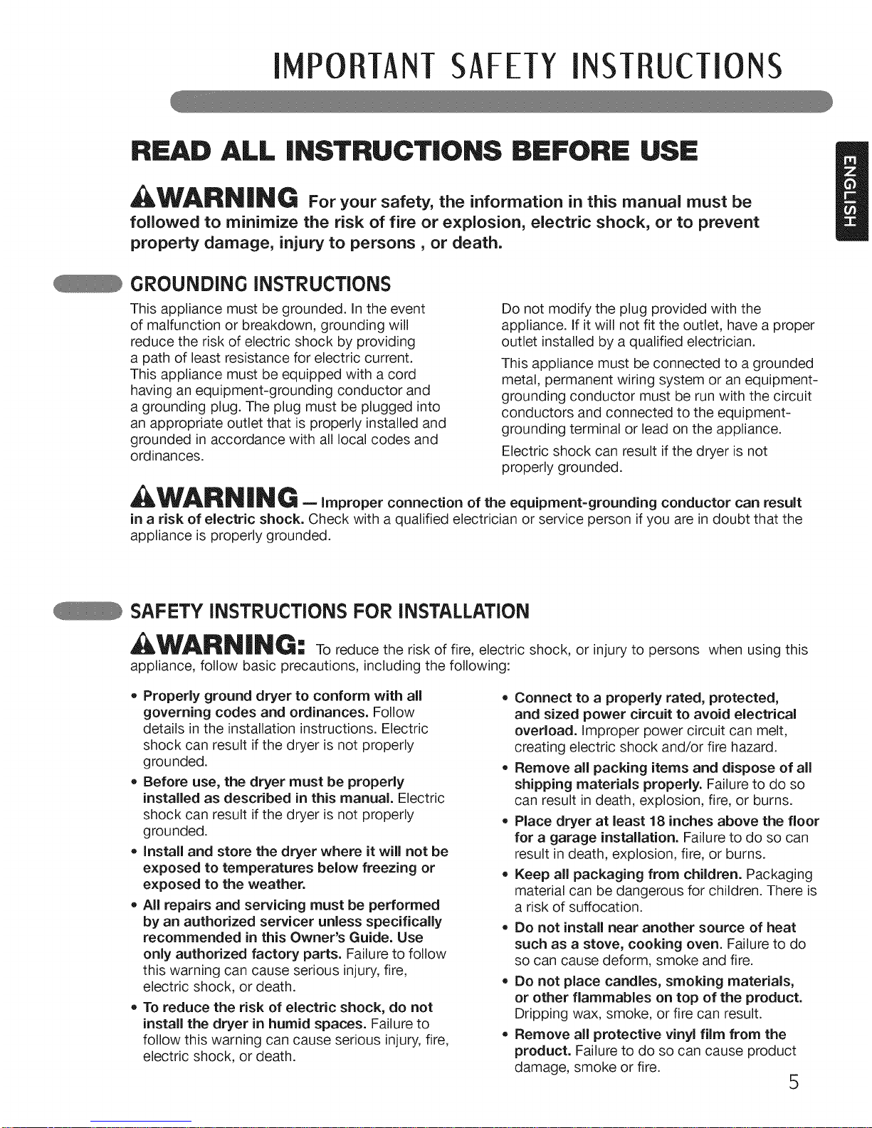
GROUNDING iNSTRUCTiONS
This appliance must be grounded. In the event
of malfunction or breakdown, grounding will
reduce the risk of electric shock by providing
a path of least resistance for electric current.
This appliance must be equipped with a cord
having an equipment-grounding conductor and
a grounding plug. The plug must be plugged into
an appropriate outlet that is properly installed and
grounded in accordance with all local codes and
ordinances.
Do not modify the plug provided with the
appliance. If it will not fit the outlet, have a proper
outlet installed by a qualified electrician.
This appliance must be connected to a grounded
metal, permanent wiring system or an equipment-
grounding conductor must be run with the circuit
conductors and connected to the equipment-
grounding terminal or lead on the appliance.
Electric shock can result if the dryer is not
properly grounded.
,WARN iN G -Improperconnectionoftheequipment-groundingconductorcanresult
in a risk of electric shock. Check with a qualified electrician or service person if you are in doubt that the
appliance is properly grounded.
SAFETY INSTRUCTIONS FOR INSTALLATION
_I_WARNiNG ==To reduce the risk of fire, electric shock, or injury to persons when using this
appliance, follow basic precautions, including the following:
* Properly ground dryer to conform with all
governing codes and ordinances. Follow
details in the installation instructions. Electric
shock can result if the dryer is not properly
grounded.
* Before use, the dryer must be properly
installed as described in this manual. Electric
shock can result ifthe dryer is not properly
grounded.
* Install and store the dryer where it will not be
exposed to temperatures below freezing or
exposed to the weather.
* All repairs and servicing must be performed
by an authorized servicer unless specifically
recommended in this Owner's Guide. Use
only authorized factory parts. Failure to follow
this warning can cause serious injury, fire,
electric shock, or death.
* To reduce the risk of electric shock, do not
install the dryer in humid spaces. Failure to
follow this warning can cause serious injury,fire,
electric shock, or death.
* Connect to a properly rated, protected,
and sized power circuit to avoid electrical
overload, improper power circuit can melt,
creating electric shock and/or fire hazard.
* Remove all packing items and dispose of all
shipping materials properly. Failure to do so
can result in death, explosion, fire, or burns.
Place dryer at least 18 inches above the floor
for a garage installation. Failure to do so can
result in death, explosion, fire, or burns.
Keep all packaging from children. Packaging
material can be dangerous for children. There is
a risk of suffocation.
* Do not install near another source of heat
such as a stove, cooking oven. Failure to do
so can cause deform, smoke and fire.
* Do not place candles, smoking materials,
or other flammables on top of the product.
Dripping wax, smoke, or fire can result.
* Remove all protective vinyl film from the
product. Failure to do so can cause product
damage, smoke or fire.
5
! PORTANTSAFETYINST UCTIONS
READ ALL iNSTRUCTiONS BEFORE USE
,WARNING For your safety,the information in this manual must be
followed to minimize the risk of fire or explosion, electric shock, or to prevent
property damage, injury to persons, or death.
SAFETY iNSTRUCTiONS FOR iNSTALLATiON
WARNING"
[] To reduce the risk of injuryto persons, follow all industry recommended safety
procedures including the use of long sleeved gloves and safety glasses. Failure to follow all of the safety
warnings in this manual could result in property damage, injury to persons or death.
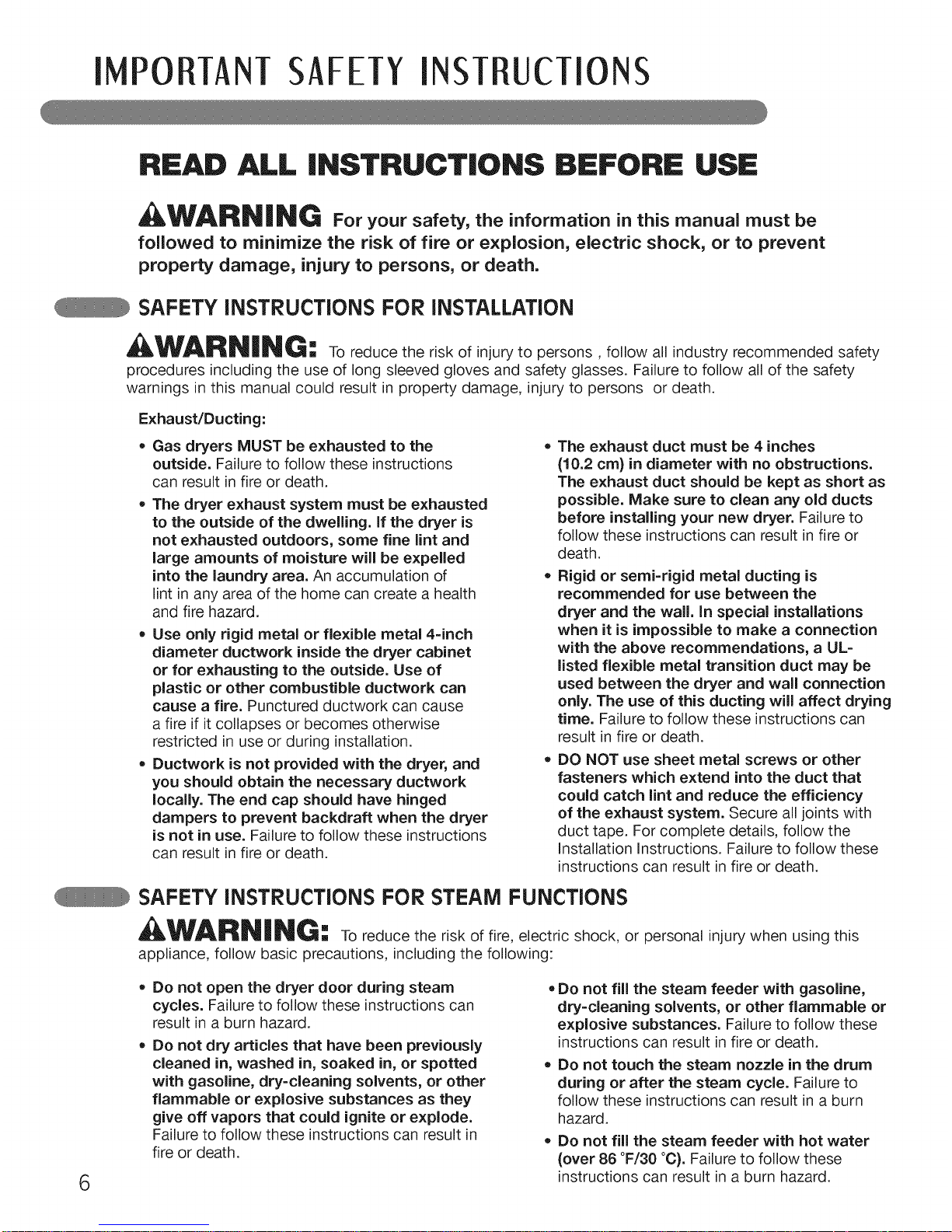
Exhaust/Ducting:
, Gas dryers MUST be exhausted to the
outside. Failure to follow these instructions
can result in fire or death.
• The dryer exhaust system must be exhausted
to the outside of the dwelling. If the dryer is
not exhausted outdoors, some fine lint and
large amounts of moisture will be expelled
into the laundry area. An accumulation of
lint in any area of the home can create a health
and fire hazard.
• Use only rigid metal or flexible metal 4-inch
diameter ductwork inside the dryer cabinet
or for exhausting to the outside. Use of
plastic or other combustible ductwork can
cause a fire. Punctured ductwork can cause
a fire if it collapses or becomes otherwise
restricted in use or during installation.
• Ductwork is not provided with the dryer, and
you should obtain the necessary ductwork
locally. The end cap should have hinged
dampers to prevent backdraft when the dryer
is not in use. Failure to follow these instructions
can result in fire or death.
, The exhaust duct must be 4 inches
(10.2 cm} in diameter with no obstructions.
The exhaust duct should be kept as short as
possible. Make sure to clean any old ducts
before installing your new dryer. Failure to
follow these instructions can result in fire or
death.
• Rigid or semi-rigid metal ducting is
recommended for use between the
dryer and the wall. In special installations
when it is impossible to make a connection
with the above recommendations, a UL=
listed flexible metal transition duct may be
used between the dryer and wall connection
only. The use of this ducting will affect drying
time. Failure to follow these instructions can
result in fire or death.
, DO NOT use sheet metal screws or other
fasteners which extend into the duct that
could catch lint and reduce the efficiency
of the exhaust system. Secure all joints with
duct tape. For complete details, follow the
Installation Instructions. Failure to follow these
instructions can result in fire or death.
SAFETY INSTRUCTIONS FOR STEAM FUNCTIONS
WARNING,
[] To reduce the risk of fire, electric shock, or personal injury when using this
appliance, follow basic precautions, including the following:
6
Do not open the dryer door during steam
cycles. Failure to follow these instructions can
result in a burn hazard.
Do not dry articles that have been previously
cleaned in, washed in, soaked in, or spotted
with gasoline, dry=cleaning solvents, or other
flammable or explosive substances as they
give off vapors that could ignite or explode.
Failure to follow these instructions can result in
fire or death.
• Do not fill the steam feeder with gasoline,
dry=cleaning solvents, or other flammable or
explosive substances. Failure to follow these
instructions can result in fire or death.
Do not touch the steam nozzle in the drum
during or after the steam cycle. Failure to
follow these instructions can result in a burn
hazard.
Do not fill the steam feeder with hot water
(over 86 °F/30 °C). Failure to follow these
instructions can result in a burn hazard.
I PORTANTSAFETYINSTRUCTIONS
READ ALL INSTRUCTIONS BEFORE USE
_WARNING Foryo.rsafety,theinformationinthisman.alre.stbe
followed to minimize the risk of fire or explosion, electric shock, or to prevent
property damage, injury to persons, or death.
SAFETY iNSTRUCTiONS FOR CONNECTING ELECTRiCiTY
_WARNING: To reduce the risk of fire, electric shock, or injury to persons when using this
appliance, follow basic precautions, including the following:
, Do not, under any circumstances, cut or
remove the ground prong from the power
cord. To prevent injury to persons or damage
to the dryer, the electrical power cord must be
plugged into a properly grounded outlet.
• For personal safety, this dryer must be
properly grounded. Failure to do so can result
in electric shock or injury.
, Refer to the installation instructions in this
manual for specific electrical requirements
for your model. Failure to follow these
instructions can create an electric shock hazard
and/or a fire hazard.
• This dryer must be plugged into a properly
grounded outlet. Electric shock can result if
the dryer is not properly grounded. Have the
wall outlet and circuit checked by a qualified
electrician to make sure the outlet is properly
grounded. Failure to follow these instructions
can create an electric shock hazard and/or a fire
hazard.
• The dryer should always be plugged into
its own individual electrical outlet which
has a voltage rating that matches the rating
plate. This provides the best performance
and also prevents overloading house wiring
circuits which could cause a fire hazard from
overheated wires.
, Never unplug your dryer by pulling on the
power cord. Always grip plug firmly and pull
straight out from the outlet. The power cord
can be damaged, resulting in a risk of fire and
electric shock.
• Repair or replace immediately all power
cords that have become frayed or otherwise
damaged. Do not use a cord that shows
cracks or abrasion damage along its length
or at either end. The power cord can melt,
creating an electric shock and/or fire hazard.
• When installing or moving the dryer, be
careful not to pinch, crush, or damage
the power cord. This will prevent injury and
prevent damage to the dryer from fire and
electric shock.
SAVE THESE INSTRUCTIONS
7

PARTSAND FEATURES
SPECIAL FEATURES
@
O
e
EASY-TO-USE CONTROL PANEL
Rotate the cycle selector knob to select the
desired dry cycle. Add cycle options or adjust
settings with the touch of a button.
EASY-ACCESS REVERSIBLE DOOR
The wide-opening door provides easy access for
loading and unloading. The door hinge can be
reversed to adjust for installation location.
STEAM FUNCTIONS
LG's steam technology allows you to inject
fabrics with a swirling jet of hot steam to refresh
clothes, reduce static, and make ironing easier.
Simply select the STEAMFRESH TMcycle, or you
can add a Steam option to selected cycles.
_) FLOW SENSE TM DUCT BLOCKAGE SENSING
SYSTEM IN DICATOR
O
The FLOW SENSE TM duct blockage sensing
system detects and alerts you to blockages in
the ductwork that reduce exhaust flow from the
dryer. Clean exhaust systems increase efficiency
and reduce drying times.
SMARTDIAGNOSIS TM
Should you experience any technical difficulty
with your dryer, it has the capability of
transmitting data via your telephone to the
Customer Information Center. The call center
agent records the data transmitted from your
machine and uses it to analyze the issue,
providing a fast and effective diagnosis (refer to
page 41).
O
8
PARTSAND FEATU ES
@
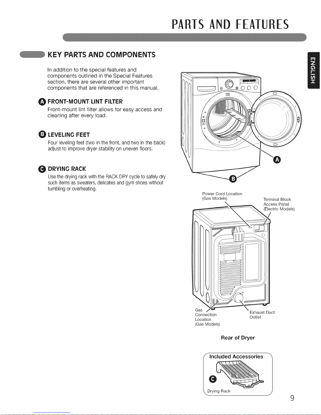
KEY PARTS AND COMPONENTS
In addition to the special features and
components outlined in the Special Features
section, there are several other important
components that are referenced in this manual.
FRONT-MOUNT LINT FILTER
Front-mount lint filter allows for easy access and
cleaning after every load.
LEVELING FEET
Four leveling feet (two in the front, and two in the back)
adjust to improve dryer stability on uneven floors,
DRYING RACK
Usethe drying rack with the RACKDRYcycle to safelydry
such itemsas sweaters,delicates and gym shoeswithout
tumbling or overheating.
....... _ ...... J
Power Cord Location
(Gas Models)
Terminal Block
Access Panel
(Electric Models)
Gas
Connection
Location
(Gas Models)
Exhaust Duct
Outlet
Rear of Dryer
9
INSTALLATIONINSTRUcTiONS
WARNING: Read all installation instructions completely before installing
and operating your dryer!
It is important that you review this entire manual before installing and using your dryer. Detailed instructions concerning
electrical connections, gas connections, and exhaust requirements are provided on the following pages.
INSTALLATIONLOCATION REOUIREMENTS
[] A location that allows for proper exhaust installation. [] A level floor with a maximum slope of 1 inch (2.5 cm)
A gas dryer must be exhausted to the outdoors. See
Venting Requirements.
[] A grounded electrical outlet located within 2 ft.
(61 cm) of either side of the dryer. See Electrical
Requirements.
[] A sturdy floor to support the total dryer weight of
200 Ibs (90.7 kg). The combined weight of a companion
appliance should also be considered.
[]
under entire dryer. If slope is greater than 1 inch (2.5
cm), install the Extended Dryer Feet Kit. Clothes may
not tumble properly, and automatic sensor cycles may
not operate correctly if dryer is not level.
For a garage installation, you will need to place the dryer
at least 18 inches (46 cm) above the floor. If using a
pedestal, you will need 18 inches (46 cm) to the bottom
of the dryer.
Do not operate your dryer at temperatures below 45 °F (7 °C). At lower temperatures, the dryer might not shut off at the
end of an automatic cycle. This can result in longer drying times.
The dryer must not be installed or stored in an area where it will be exposed to water and/or weather.
Check code requirements. Some codes limit, or do not permit, installation of the dryer in garages, closets, mobile
homes or sleeping quarters. Contact your local building inspector.
NOTE: No other fuel-burning appliance can be installed in the same closet as a dryer.
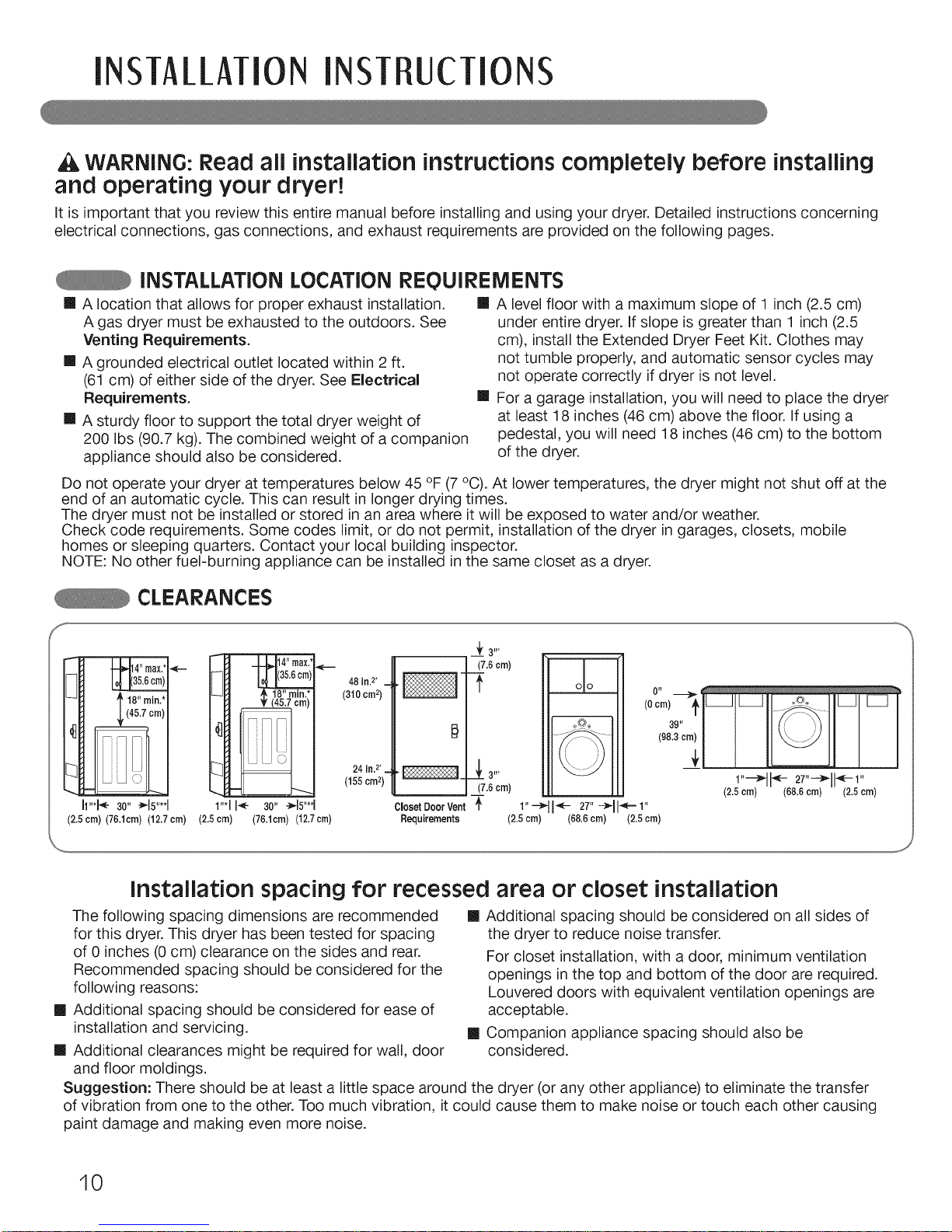
CLEARANCES
f 16,,mid
h"*}'_- 30" _15"**1
(2.5cm) (76.1cm) (12.7 cm)
_1 4-1d14"m0x1.,_
_ H 1(35'6cm)1'=._ _ 48in.2. _
(310cm2)
_._ 24 in.2._
(155crn2)
1"'1 I_" 30" -_15"**_
(2.5 crn) (78.1cm) (12.7crn)
(2.5cm)
11,---_11_-27,,--_11_-1,,
(2.5cm) (68.6cm) (2.5cm)
......J
installation spacing for recessed area or closet installation
The following spacing dimensions are recommended [] Additional spacing should be considered on all sides of
for this dryer. This dryer has been tested for spacing
of 0 inches (0 cm) clearance on the sides and rear.
Recommended spacing should be considered for the
following reasons:
[] Additional spacing should be considered for ease of
installation and servicing.
[] Additional clearances might be required for wall, door
and floor moldings.
[]
the dryer to reduce noise transfer.
For closet installation, with a door, minimum ventilation
openings in the top and bottom of the door are required.
Louvered doors with equivalent ventilation openings are
acceptable.
Companion appliance spacing should also be
considered.
Suggestion: There should be at least a little space around the dryer (or any other appliance) to eliminate the transfer
of vibration from one to the other. Too much vibration, it could cause them to make noise or touch each other causing
paint damage and making even more noise.
10
INSTAI_I_ATIONiNSTRUcTIONS
iNSTALLATiON WITH OPTIONAL PEDESTAL BASE OR STACKING KiT
_WARNING : If you are installing your dryer using an optional pedestal base or stacking kit, please
refer to Optional Accessories in this manual or to the instructions for your pedestal or stacking kit
before proceeding with the installation.
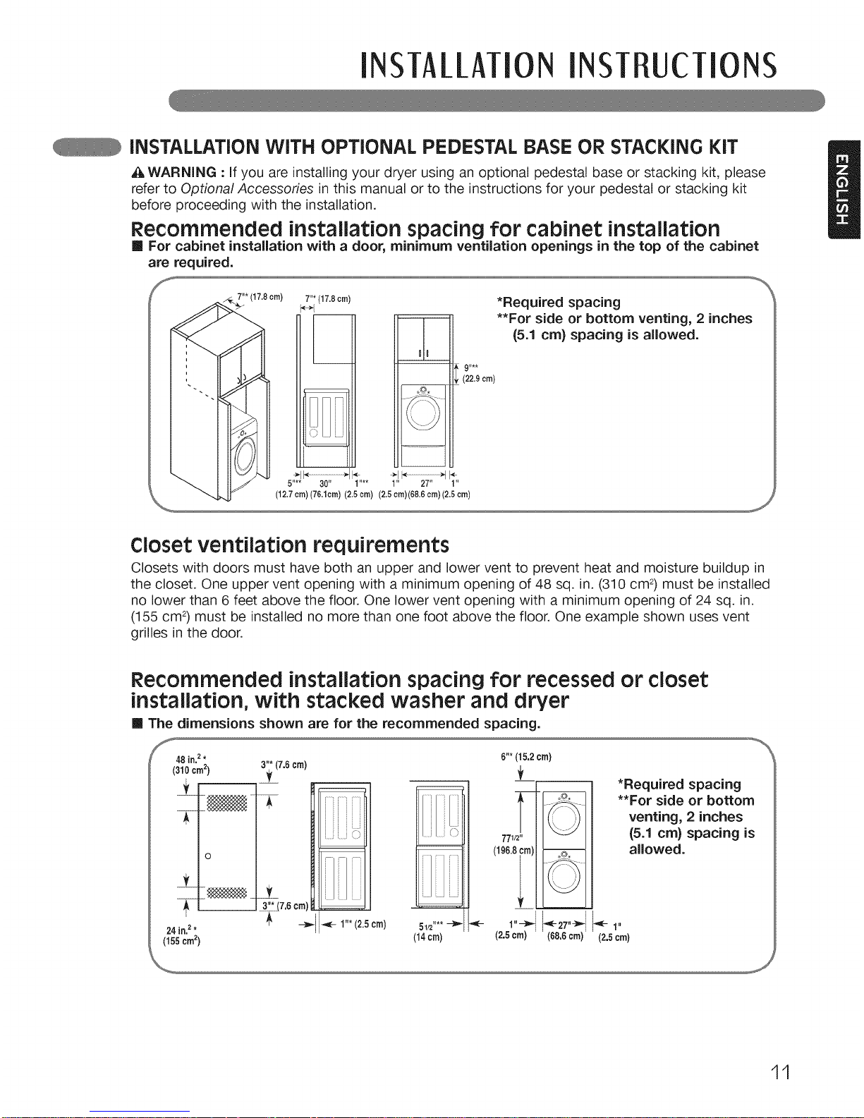
Recommended installation spacing for cabinet installation
[] For cabinet installation with a door, minimum ventilation openings in the top of the cabinet
are required.
7"*(17.8crn)
7"*(17.8crn)
u!o
)[JLJ
5.... 30" 1.... 1" 27" 1"
(12,7 crn) (76,10m) (2,5 ore) (2,5 0rn)(68.6 cm) (2,5 ore)
*Required spacing
**For side or bottom venting, 2 inches
(5.1 cm) spacing is allowed.
91,**
(22.9 cm)
J
Closet ventilation requirements
Closets with doors must have both an upper and lower vent to prevent heat and moisture buildup in
the closet. One upper vent opening with a minimum opening of 48 sq. in. (310 cm 2)must be installed
no lower than 6 feet above the floor. One lower vent opening with a minimum opening of 24 sq. in.
(155 cm2)must be installed no more than one foot above the floor. One example shown uses vent
grilles in the door.
Recommended installation spacing for recessed or closet
installation, with stacked washer and dryer
[] The dimensions shown are for the recommended spacing.
48 in.2* 6"* (15,2 crn)
(310 cm2) 3"_7.6 cm)
f
0
_"*(7,5 cm)___
24 in.2*
(155crn2)
_- 1"* (2.5cm)
5112"** --_
(14cm)
771/2"
(196.8_m)
1"-_- _-- 27,,-_
(2.5 cm) (68,6 cm)
*Required spacing
**For side or bottom
venting, 2 inches
(5.1 cm) spacing is
allowed.
(2.5era)
J
11
INSTAllATION iNSTRUcTIONS
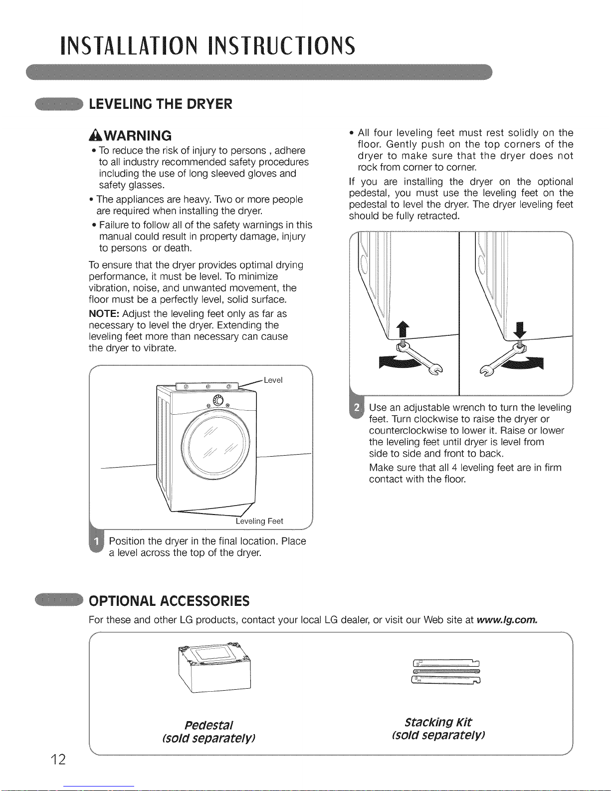
LEVELING THE DRYER
,WARNING
• To reduce the risk of injuryto persons, adhere
to all industry recommended safety procedures
including the use of long sleeved gloves and
safety glasses.
• The appliances are heavy. Two or more people
are required when installing the dryer.
• Failure to follow all of the safety warnings in this
manual could result in property damage, injury
to persons or death.
To ensure that the dryer provides optimal drying
performance, it must be level. To minimize
vibration, noise, and unwanted movement, the
floor must be a perfectly level, solid surface.
NOTE: Adjust the leveling feet only as far as
necessary to level the dryer. Extending the
leveling feet more than necessary can cause
the dryer to vibrate.
• All four leveling feet must rest solidly on the
floor. Gently push on the top corners of the
dryer to make sure that the dryer does not
rock from corner to corner.
If you are installing the dryer on the optional
pedestal, you must use the leveling feet on the
pedestal to level the dryer. The dryer leveling feet
should be fully retracted.
_ Level
Leveling Feet
Position the dryer in the final location. Place
a level across the top of the dryer.
Use an adjustable wrench to turn the leveling
feet. Turn clockwise to raise the dryer or
counterclockwise to lower it. Raise or lower
the leveling feet until dryer is level from
side to side and front to back.
Make sure that all 4 leveling feet are in firm
contact with the floor.
OPTIONAL ACCESSORIES
For these and other LG products, contact your local LG dealer, or visit our Web site at www.lg.com.
12
Pedestal Stacking Kit
(sold separatelW (sold separately)
INSTAllATION INSTRUCTIONS
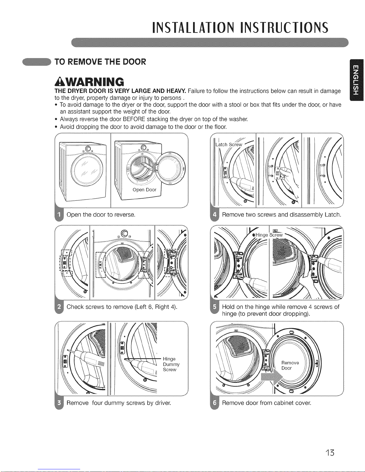
TO REMOVE THE DOOR
WARNING U
THE DRYER DOOR iS VERY LARGE AND HEAVY. Failure to follow the instructionsbelow can result indamage
to the dryer, property damage or injury to persons.
• To avoid damage to the dryer or the door, support the door with a stool or box that fits under the door, or have
an assistant support the weight of the door.
Always reverse the door BEFORE stacking the dryer on top of the washer.
Avoid dropping the door to avoid damage to the door or the floor.
Open the door to reverse.
_J
Open Door
\o\\
% \
Remove two screws and disassembly Latch.
crews to remove (Left 6, Right 4). Hold on the hinge while remove 4 screws of
hinge (to prevent door dropping).
® _ HIn e
s )b
s by driver
15
INSTAllATION INSTRUCTIONS
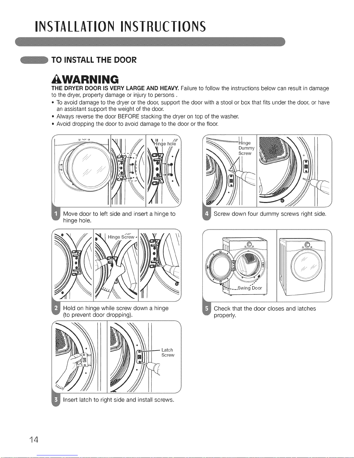
TO iNSTALL THE DOOR
WARN|NG
THE DRYER DOOR IS VERY LARGE AND HEAVY. Failure to follow the instructionsbelow can result in damage
to the dryer, property damage or injury to persons.
• To avoid damage to the dryer or the door, support the door with a stool or box that fits under the door, or have
an assistant support the weight of the door.
Always reverse the door BEFOREstacking the dryer on top of the washer.
Avoid dropping the door to avoid damage to the door or the floor.
Move door to left side and insert a hinge to
hinge hole.
o
o
fJJ
0 Hinge Screw,
Hold on hinge while screw down a hinge
(to prevent door dropping).
oJ
Latch
Screw
Insert latch to right side and install screws.
__Hinge
"_,_ Dummy
,. "_. \\\ Screw
Screw down four dummy screws right side.
Check that the door closes and latches
properly.
I
14
INSTAllATION INSTRUCTIONS
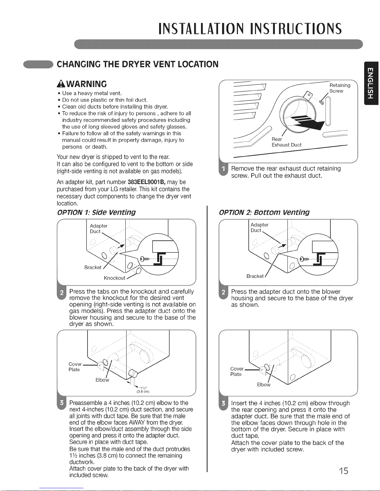
cHANGiNG THE DRYER VENT LOcATiON
WARNING
• Use a heavy metal vent.
= Do not use plastic or thin foil duct.
• Clean old ducts before installing this dryer.
• To reduce the risk of injury to persons, adhere to all
industry recommended safety procedures including
the use of long sleeved gloves and safety glasses.
=Failureto follow all of the safety warnings inthis
manualcould result in property damage, injuryto
persons or death.
Your new dryer isshipped to vent to the rear.
It can also be configured to vent to the bottom or side
(right-side venting is not available on gas models).
An adapter kit, part number 383EELg001B, may be
purchased from your LGretailer.This kit contains the
necessary duct components to change the dryer vent
location.
OPTION 1: Side venting
Adapter
Duct
Press the tabs on the knockout and carefully
remove the knockout for the desired vent
opening (right-side venting is not available on
gas models). Press the adapter duct onto the
blower housing and secure to the base of the
dryer as shown.
Plate
Elbo_
Preassemble a 4 inches (10.2 cm) elbow to the
next 4-inches (10.2 cm) duct section, and secure
all joints with duct tape. Be sure that the male
end of the elbow faces AWAYfrom the dryer.
Insert the elbow/duct assembly through the side
opening and press it onto the adapter duct.
Secure in place with duct tape.
Be sure that the male end of the duct protrudes
11/2inches (3.8 cm) to connect the remaining
ductwork.
Attach cover plate to the back of the dryer with
included screw.
Retaining
Screw
Rear
Exhaust Duct
Remove the rear exhaust duct retaining
screw. Pull out the exhaust duct.
OPTION 2: BOttOm venting
Adapter
f,
Bracket
Press the adapter duct onto the blower
housing and secure to the base of the dryer
as shown.
Plate
Insert the 4 inches (10.2 cm) elbow through
the rear opening and press it onto the
adapter duct. Be sure that the male end of
the elbow faces down through hole in the
bottom of the dryer. Secure in place with
duct tape.
Attach the cover plate to the back of the
dryer with included screw.
_J
15
INSTALLATIONINSTRUCTIONS
VENTING THE DRYER
WARNiNG,
[] To reduce the risk of fire, electric shock, or injury to persons
appliance, follow basic precautions, including the following:
when using this
• Do not crush or collapse ductwork. Failure
to follow these instructions can result in fire
or death.
Do not allow ductwork to rest on or
contact sharp objects. Failure to follow these
instructions can result in fire or death.
• if connecting to existing ductwork, make
sure it is suitable and clean before installing
the dryer. Failure to follow these instructions
can result in fire or death.
• Venting must conform to local building
codes. Failure to follow these instructions can
result in fire or death.
Gas dryers MUST exhaust to the outdoors.
Failure to follow these instructions can result
in fire or death.
• Use only 4-inch (10.2 cm) rigid or flexible
metal ductwork inside the dryer cabinet and
for venting outside. Failure to follow these
instructions can result in fire or death.
• To reduce the risk of fire, combustion, or
accumulation of combustible gases, DO
NOT exhaust dryer air into an enclosed and
unventilated area, such as an attic, wall,
ceiling, crawl space, chimney, gas vent, or
concealed space of a building. Failure to
follow these instructions can result in fire
or death.
=To reduce the risk of fire, DO NOT exhaust
the dryer with plastic or thin foil ducting.
Failure to follow these instructions can result
in fire or death.
The exhaust duct must be 4 inches
(10.2 cm} in diameter with no obstructions.
The exhaust duct should be kept as short as
possible. Make sure to clean any old ducts
before installing your new dryer. Failure to
follow these instructions can result in fire or
death.
Rigid or semirigid metal ducting is
recommended for use between the dryer
and the wall. in special installations when
it is impossible to make a connection with
the above recommendations, a UL=listed
flexible metal transition duct may be used
between the dryer and wall connection only.
The use of this ducting will affect drying
time. Failure to follow these instructions can
result in fire or death.
DO NOT use sheet metal screws or other
fasteners which extend into the duct that
could catch lint and reduce the efficiency
of the exhaust system. Secure all joints
with duct tape. Failure to follow these
instructions can result in fire or death.
• To maximize operating results, please
observe the duct length limitations noted in
the chart on page 17. Failure to follow these
instructions can result in fire or death.
Ductwork is not provided with the dryer.
You should obtain the necessary ductwork
locally. The end cap should have hinged
dampers to prevent backdraft when the
dryer is not in use. Failure to follow these
instructions can result in fire or death.
The Total length of flexible metal duct shall
not exceed 8 ft. (2.4m)
• in Canada, that only those foil-type flexible
ducts, if any, specifically identified for use
with the appliance by the manufacturer
shall be used. In the United States, that only
those foil-type flexible ducts, if any, specifically
identified for use with the appliance by the
manufacturer and that comply with the Outline
for Clothes Dryer Transition Duct, Subject
2158A, shall be used.
16
INSTAllATION iNSTRUcTIONS
VENTING THE DRYER {cont.)
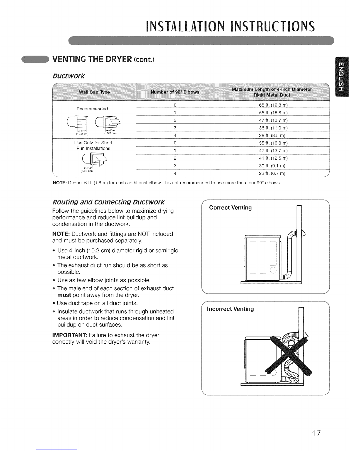
Ductwork
Recommended
(10.2 cm) (10.2 cm)
Use Only for Short
Run Installations
(6.35 cm)
o
1
2
3
4
o
1
2
3
4
65 ft. (19.8 m)
55 ft. (16.8 m)
47 ft. (13.7 m)
36 ft. (11.0 m)
28ft._
55 ft. (16.8 m)
47 ft. (13.7 m)
41 ft. (12.5 m)
30 ft. (9.1 m)
22 ft. (6.7 m)
NOTE: Deduct 6 ft. (1.8 m) for each additional elbow. It is not recommended to use more than four 90° elbows.
J
ROuting and Connecting Ductwork
Follow the guidelines below to maximize drying
performance and reduce lint buildup and
condensation in the ductwork,
NOTE: Ductwork and fittings are NOT included
and must be purchased separately.
• Use 4-inch (10,2 cm) diameter rigid or semirigid
metal ductwork,
• The exhaust duct run should be as short as
possible,
• Use as few elbow joints as possible.
• The male end of each section of exhaust duct
must point away from the dryer.
• Use duct tape on all duct joints,
• Insulate ductwork that runs through unheated
areas in order to reduce condensation and lint
buildup on duct surfaces.
iMPORTANT: Failure to exhaust the dryer
correctly will void the dryer's warranty.
Correct Venting
i i /_,
JL '
incorrect Venting
17

INSTAllATION INSTRUCTIONS
cONNEcTiNG GAS DRYERS
WARNiNG',
appliance, follow basic precautions, including the following:
* Gas supply requirements: *
As shipped from the factory, this dryer is
configured for use with natural gas. it can be
converted for use with LP (Liquefied Propane)
gas. Gas pressure must not exceed 13 inches
of water column.
o A qualified service or gas company technician
must connect the dryer to the gas service.
Failure to do so can result in fire, explosion,
or death.
o Isolate the dryer from the gas supply system •
by closing its individual manual shutoff valve
during any pressure testing of the gas supply.
Failure to do so can result in fire, explosion,
or death.
Supply line requirements:
Your laundry room must have a rigid gas
supply line to your dryer. In the United States,
an individual manual shutoff valve MUST be •
installed within at least 6 ft. (1.8 m) of the dryer,
in accordance with the National Fuel Gas Code
o
ANSI Z223.1 or Canadian gas installation code
CSA B149.1. A 1/8- inch NPT pipe plug must
be installed. Failure to do so can result in fire,
explosion, or death
o
o If using a rigid pipe, the rigid pipe should be
1/2- inch IPS. If acceptable under local codes
and ordinances and when acceptable to your
gas supplier, 3/8- inch approved tubing may be
used where lengths are less than 20 ft.
(6.1 m). Larger tubing should be used for
lengths in excess of 20 ft. (6.1 m). Failure to do
so can result in fire, explosion, or death.
To reduce the risk of fire, electric shock, or injury to persons when using this
Connect the dryer to the type of gas shown on
the nameplate. Failure to do so can result in fire,
explosion, or death.
To prevent contamination of the gas valve,
purge the gas supply of air and sediment
before connecting the gas supply to the dryer.
Before tightening the connection between the
gas supply and the dryer, purge remaining air
until the odor of gas is detected. Failure to do
so can result in fire, explosion, or death.
DO NOT use an open flame to inspect for gas
leaks. Use a noncorrosive leak-detection fluid.
Failure to do so can result in fire, explosion, or
death.
Use only a new AGA- or CSA-certified gas
supply line with flexible stainless steel
connectors. Failure to do so can result in fire,
explosion, or death.
Securely tighten all gas connections. Failure
to do so can result in fire, explosion, or death.
Use a pipe-joint compound that is insoluble
in Liquefied Petroleum (LP) gas on all pipe
threads. Failure to do so can result in fire,
explosion, or death.
DO NOT attempt any disassembly of the dryer;
any disassembly requires the attention and
tools of an authorized and qualified service
person or company. Failure to do so can result
in fire, explosion, or death.
Electrical Requirements for Gas MOdelS Only
WARNING.
[] To reduce the risk of fire, electric shock, or injury to persons when using this
appliance, follow basic precautions, including the following:
• Do not, under any circumstances, cut or
remove the third (ground) prong from the power
cord. Failure to follow this warning can result in
fire, explosion, or death.
For personal safety, this dryer must be properly
grounded. Failure to follow this warning can result
in fire, explosion, or death.
The power cord of this dryer is equipped with
a 3-prong (grounding) plug which mates with
a standard 3-prong (grounding) wall outlet
to minimize the possibility of electric shock
hazard from this appliance. Failure to follow this
warning can result in fire, explosion, or death.
* This dryer must be plugged into a
60 Hz, 120 VAC. grounded outlet protected by
a 15-ampere fuse or circuit breaker. Failure to
follow this warning can result in fire, explosion,
or death.
o Where a standard 2-prong wall outlet is
encountered, it is your personal responsibility
and obligation to have it replaced with a
properly grounded 3-prong wall outlet. Failure
to follow this warning can result in fire, explosion,
or death.
18
INSTAllATIONINSTRUCTIONS
cONNEcTiNG GAS DRYERS (cont.)
WARNING:
appliance, follow basic precautions, including the following:
• installation and service must be performed
by a qualified installer, service agency, or the
gas supplier. Failure to do so can result in fire,
explosion, or death.
• Use only a new stainless steel flexible
connector and a new AGA=certified
connector. Failure to do so can result in fire,
explosion, or death.
• A gas shutoff valve must be installed within
6 ft. (1.8 m) of the dryer. Failure to do so can
result in fire, explosion, or death.
• The dryer is configured for Natural Gas when
shipped from the factory. Make sure that the
dryer is equipped with the correct burner
orifice for the type of gas being used (Natural
Gas or Liquefied Petroleum). Failure to do so
can result in fire, explosion, or death.
To reduce the risk of fire, electric shock, or injury to persons when using this
If necessary, the correct orifice (for the LP
orifice kit order part number 383EEL3002D)
should be installed by a qualified technician
and the change should be noted on the dryer.
Failure to do so can result in fire, explosion,
or death.
All connections must be in accordance with
local codes and regulations. Failure to do so
can result in fire, explosion, or death.
Gas dryers MUST exhaust to the outdoors.
Failure to do so can result in fire, explosion,
or death.
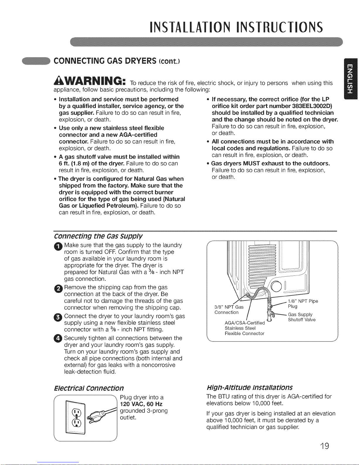
Connecting the Gas Supply
t_ Make sure that the gas supply to the laundry
room is turned OFR Confirm that the type
of gas available in your laundry room is
appropriate for the dryer. The dryer is
prepared for Natural Gas with a %- inch NPT
gas connection.
O Remove the shipping cap from the gas
connection at the back of the dryer. Be
careful not to damage the threads of the gas
connector when removing the shipping cap.
O Connect the dryer to your laundry room's gas
supply using a new flexible stainless steel
connector with a % - inch NPT fitting.
O Securely all connections between the
tighten
dryer and your laundry room's gas supply.
Turn on your laundry room's gas supply and
check all pipe connections (both internal and
external) for gas leaks with a noncorrosive
leak-detection fluid.
Electrical Connection
Plug dryer into a
120 VAC, 60 Hz
grounded 3-prong
outlet.
Shutoff Valve
AGA/CSA-Certified
Stainless Steel
Flexible Connector
Hig#-Altitude Installations
The BTU rating of this dryer is AGA-certified for
elevations below 10,000 feet.
If your gas dryer is being installed at an elevation
above 10,000 feet, it must be derated by a
qualified technician or gas supplier.
19
INSTA[[MION INST UcTIONS
cONNEcTiNG ELEcTRic DRYERS
WARNiNG"
m To help prevent fire, electric shock, serious injury, or death, the wiring and
grounding must conform to the latest edition of the National Electrical Code, ANSI/NFPA 70 and all
applicable local regulations. Please contact a qualified electrician to check your home's wiring and
fuses to ensure that your home has adequate electrical power to operate the dryer.
Electrical Requirements for Electric MOdelS Only
WARNING,
[] To reduce the risk of fire, electric shock, or injury to persons when using this
appliance, follow basic precautions, including the following:
• This dryer must be connected to a grounded
metal, permanent wiring system, or an
equipment=grounding conductor must
be run with the circuit conductors and
connected to the equipment=grounding
terminal or lead on the dryer. Failure to do
so can result in fire, explosion, or death.
• The dryer has its own terminal block that
must be connected to a separate 240 VAC,
60=Hertz, single=phase circuit, fused at 30
amperes (the circuit must be fused on both
sides of the line). ELECTRICAL SERVICE
FOR THE DRYER SHOULD BE OF THE
MAXIMUM RATE VOLTAGE LISTED ON THE
NAMEPLATE. DO NOT CONNECT DRYER =
TO 110=, 115=, OR 120-VOLT CIRCUIT. Failure
to follow these instructions can result in fire,
explosion, or death.
• if branch circuit to dryer is 15 ft. (4.5 m)
or less in length, use UL (Underwriters
Laboratories) listed No.=10 AWG wire
(copper wire only), or as required by local
codes. If over 15 ft. (4.50 m), use UL=listed
No.=8 AWG wire (copper wire only), or as
required by local codes. Allow sufficient
slack in wiring so dryer can be moved from
its normal location when necessary. Failure
to do so can result in fire, explosion, or death.
The power cord (pigtail) connection between
wall receptacle and dryer terminal block IS
NOT supplied with dryer. The pigtail must be
the correct plug and wire gauge and must
conform to local codes and with instructions
on the following pages. Failure to follow these
instructions can result in fire, explosion, or
death.
A 4-wire connection is required for all mobile
and manufactured home installations, as
well as all new construction after January
1, 1996. A 4=wire connection must be used
where local codes do not permit grounding
through the neutral wire. Failure to do so can
result in fire, explosion, or death.
WARNING', To reduce the risk of fire, electric shock, or injury to persons when using this
appliance, follow basic precautions, including the following:
• Do not modify the plug and internal wire
provided with the dryer.
oThe dryer should be connected to 4-hole outlet.
If itdoes not fit the outlet, a proper outlet will
need to be installed by a qualified electrician.
Special Electrical Requirements for Mobile or Manufactured Homes
WARNING"
[] To reduce the risk of fire, electric shock, or injury to persons when using this
appliance, follow basic precautions, including the following:
Any installation in a manufactured or mobile
home must comply with the Manufactured
Home Construction and Safety Standards
Title 24 CFR, Part 32-80 or Standard CAN/
CSAOZ240 MH and local codes and ordinances.
A 4=wire connection is required for all mobile
and manufactured home installations, as well
as all new construction after January 1, 1996.
Failure to do so can result in fire, explosion,
or death.
2O
INSTAllATIONINST UcTIONS
cONNEcTiNG ELEcTRic DRYERS {cont.)
USA ONLY
WARN|NG:
= Connect the power cord to the terminal block. Each colored wire should be connected
to same color screw. Wire color indicated on manual is connected to the same color
screw in block. Failure to follow these instructions may result in a short or overload.
= Grounding through the neutral conductor is prohibited for: (1) new branch-circuit
installations, (2) mobile homes, (3) recreational vehicles, and (4) areas where local
codes prohibit grounding through the neutral conductor.
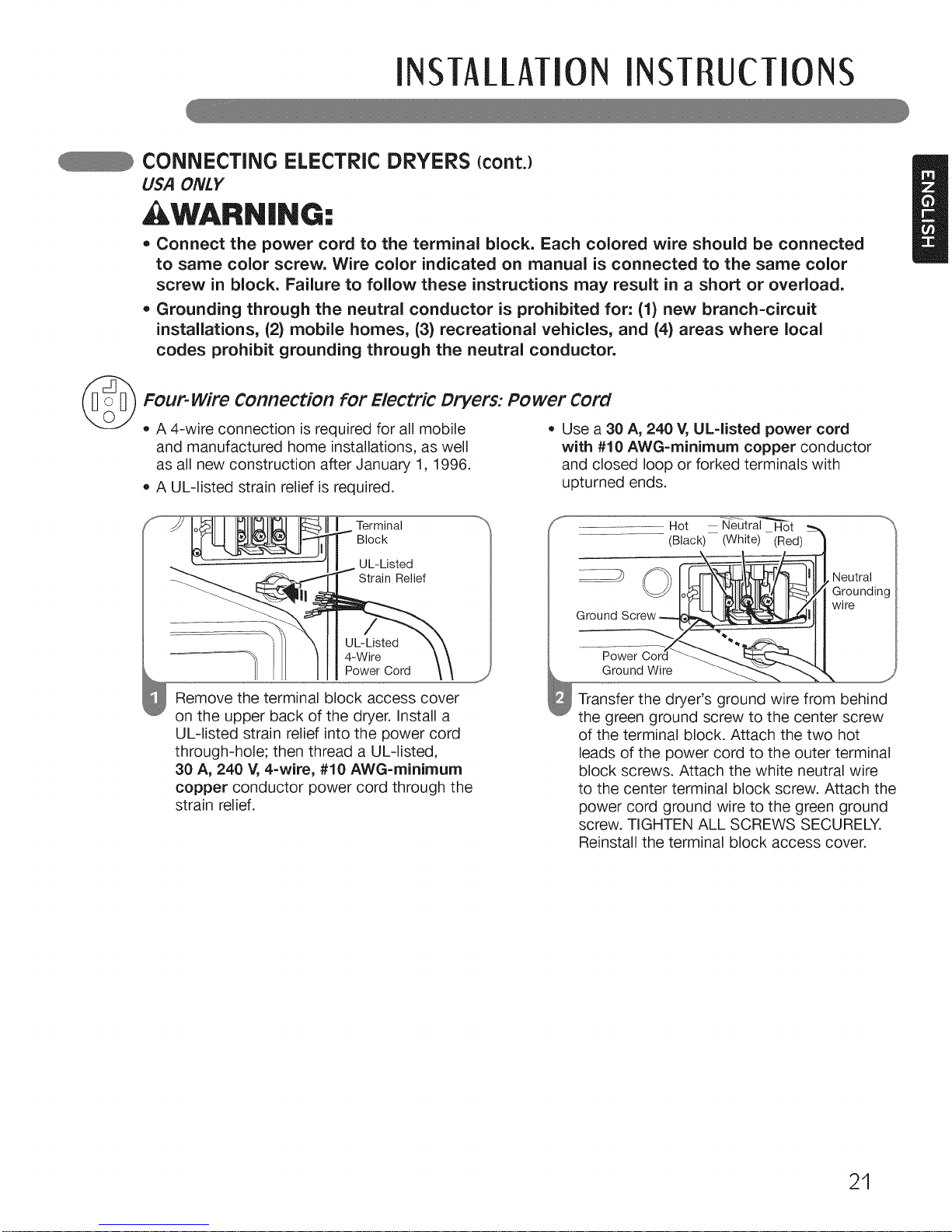
Four-wire Connection for Electric Dryers: Power Cord
• A 4-wire connection is required for all mobile
and manufactured home installations, as well
as all new construction after January 1, 1996.
A UL-listed strain relief is required.
Use a 30 A, 240 V, UL=listed power cord
with #10 AWG=minimum copper conductor
and closed loop or forked terminals with
upturned ends.
Terminal
Block
UL-Listed
Strain Relief
UL-Listed
4-Wire
Power Cord
Remove the terminal block access cover
on the upper back of the dryer. Install a
UL-listed strain relief into the power cord
through-hole; then thread a UL-listed,
30 A, 240 V, 4=wire, #10 AWG=minimum
copper conductor power cord through the
strain relief.
_,:_,,,,,,,,,,,,,,_
Hot Neutral Hot
...............................(Black) (White) (Red)
Neutral
Ground Screw
Power
Ground Wire
wire
Transfer the dryer's ground wire from behind
the green ground screw to the center screw
of the terminal block. Attach the two hot
leads of the power cord to the outer terminal
block screws. Attach the white neutral wire
to the center terminal block screw. Attach the
power cord ground wire to the green ground
screw. TIGHTEN ALL SCREWS SECURELY.
Reinstall the terminal block access cover.
21
INSTA[[ATIONINST UcTIONS
cONNEcTiNG ELEcTRic DRYERS {cont.)
USA ONLY
WARN|NG,.
= Connect the power cord to the terminal block, Each colored wire should be connected
to same color screw. Wire color indicated on manual is connected to the same color
screw in block. Failure to follow these instructions may result in a short or overload.
• Grounding through the neutral conductor is prohibited for: (1) new branch=circuit
installations, (2) mobile homes, (3) recreational vehicles, and (4) areas where local
codes prohibit grounding through the neutral conductor.
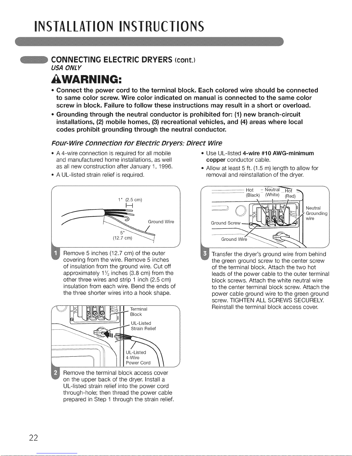
Four-wire Connection for Electric Dryers: Direct wire
• A 4-wire connection is required for all mobile
and manufactured home installations, as well
as all new construction after January 1, 1996.
A UL-listed strain relief is required.
Use UL-listed 4-wire #10 AWG=minimum
copper conductor cable.
Allow at least 5 ft. (1.5 m) length to allow for
removal and reinstallation of the dryer.
1" (2.5 cm)
I--4
f und Wire
(12.7 cm)
J
Remove 5 inches (12.7 cm) of the outer
covering from the wire. Remove 5 inches
of insulation from the ground wire. Cut off
approximately 11/2inches (3.8 cm) from the
other three wires and strip 1 inch (2.5 cm)
insulation from each wire. Bend the ends of
the three shorter wires into a hook shape.
Terminal
Block
UL-Listed
Strain Relief
UL-Listed
4-Wire
Power Cord
Remove the terminal block access cover
on the upper back of the dryer. Install a
UL-listed strain relief into the power cord
through-hole; then thread the power cable
prepared inStep 1 through the strain relief.
Transfer the dryer's ground wire from behind
the green ground screw to the center screw
of the terminal block. Attach the two hot
leads of the power cable to the outer terminal
block screws. Attach the white neutral wire
to the center terminal block screw. Attach the
power cable ground wire to the green ground
screw. TIGHTEN ALL SCREWS SECURELY.
Reinstall the terminal block access cover.
22
INSTA/[MION INST UcTIONS
cONNEcTiNG ELEcTRic DRYERS {cont.)
USA ONLY
, WARN|NG:
* Connect the power cord to the terminal block. Each colored wire should be connected
to same color screw. Wire color indicated on manual is connected to the same color
screw in block. Failure to follow these instructions may result in a short or overload.
* Grounding through the neutral conductor is prohibited for: (1) new branch-circuit
installations, (2) mobile homes, (3) recreational vehicles, and (4) areas where local
codes prohibit grounding through the neutral conductor.
_ Three-wire Connection for Electric Dryers: Power Cord
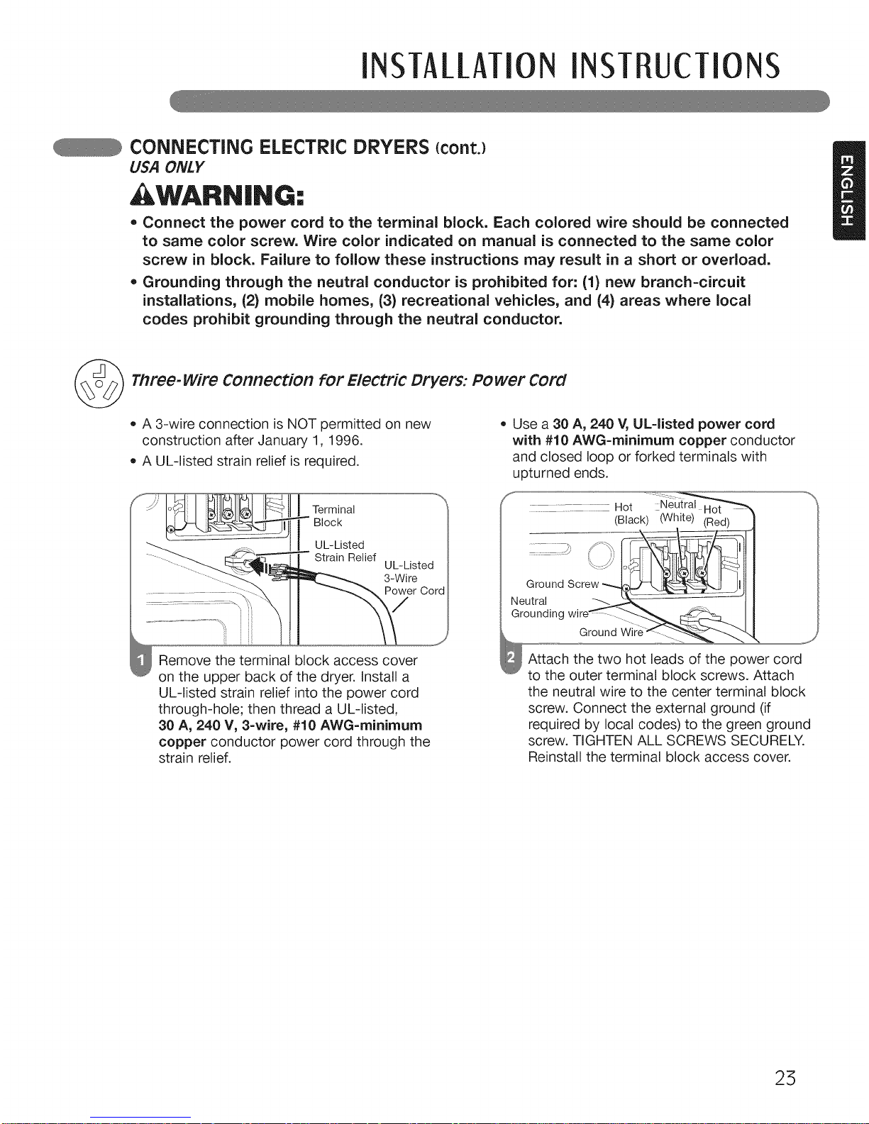
• A 3-wire connection is NOT permitted on new • Use a 30 A, 240 V, UL=listed power cord
construction after January 1, 1996. with #10 AWG=rninirnurn copper conductor
• A UL-listed strain relief is required, and closed loop or forked terminals with
upturned ends.
Terminal
Block
UL-Listed
Strain Relief
UL-Listed
3-Wire
Power Cord
.................... Hot Neutral
(Black) (White) (Red)
Neutral
Grounding
Ground Wit
Remove the terminal block access cover
on the upper back of the dryer. Install a
UL-listed strain relief into the power cord
through-hole; then thread a UL-listed,
30 A, 240 V, 3-wire, #10 AWG=minimum
copper conductor power cord through the
strain relief.
Attach the two hot leads of the power cord
to the outer terminal block screws. Attach
the neutral wire to the center terminal block
screw. Connect the external ground (if
required by local codes) to the green ground
screw. TIGHTEN ALL SCREWS SECURELY.
Reinstall the terminal block access cover.
25
INSTALLMIONINST UCTiONS
cONNEcTiNG ELEcTRic DRYERS {cont.)
USA ONLY
WARNING:
• Connect the power cord to the terminal block. Each colored wire should be connected
to same color screw. Wire color indicated on manual is connected to the same color
screw in block. Failure to follow these instructions may result in a short or overload.
• Grounding through the neutral conductor is prohibited for: (1) new branch-circuit
installations, (2) mobile homes, (3) recreational vehicles, and (4) areas where local
codes prohibit grounding through the neutral conductor.
Three-wire Connection for Electric Dryers: Direct wire
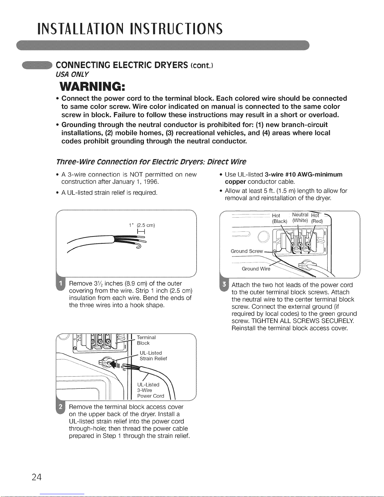
, A 3-wire connection is NOT permitted on new , Use UL-listed 3-wire #10 AWG=minirnurn
construction after January 1, 1996. copper conductor cable.
, A UL-listed strain relief is required. , Allow at least 5 ft. (1.5 m) length to allow for
removal and reinstallation of the dryer.
1" (2.5 cm)
J
Remove 31/2inches (8.9 cm) of the outer
covering from the wire. Strip 1 inch (2.5 cm)
insulation from each wire. Bend the ends of
the three wires into a hook shape.
Terminal
Block
UL-Listed
Strain Relief
UL-Listed
3-Wire
Power Cord
Remove the terminal block access cover
on the upper back of the dryer. Install a
UL-listed strain relief into the power cord
through-hole; then thread the power cable
prepared in Step 1 through the strain relief.
...... .....Hot Neutral Hot
(Black) (White) (Red)
Ground
Ground Wire
,J
Attach the two hot leads of the power cord
to the outer terminal block screws. Attach
the neutral wire to the center terminal block
screw. Connect the external ground (if
required by local codes) to the green ground
screw. TIGHTEN ALL SCREWS SECURELY.
Reinstall the terminal block access cover.
24
INSTALLMIONINST UcTIONS
SPEciAL REQUIREMENTS FOR MANUFACTURED OR MOBILE HOMES
Any installation in a manufactured or mobile
home must comply with the Manufactured Home
Construction and Safety Standards Title 24 CFR,
Part 32-80 or Standard CAN/CSAOZ240 MH and
local codes and ordinances. If you are uncertain
whether your proposed installation will comply
with these standards, please contact a service
and installation professional for assistance.
• A gas dryer must be permanently attached to
the floor.
The electrical connection for an electric dryer
must be a 4-wire connection. More detailed
information concerning the electrical connection
is provided in the section Connecting Electric
Dryers.
To reduce the risk of combustion and fire, the
dryer must be vented to the outside.
DO NOT vent the dryer under a manufactured
home or mobile home.
Electric dryers may be vented to the outside
using the back, left, right, or bottom panel.
Gas dryers may be vented to the outside using
the back, left, or bottom panel. Gas dryers may
not be vented to the outside using the right side
panel because of the burner housing.
The dryer exhaust duct must be affixed securely
to the manufactured or mobile home structure,
and the exhaust duct must be made of a
material that will resist fire and combustion.
It is recommended that you use a rigid or
flexible metal duct.
DO NOT connect the dryer exhaust duct
to any other duct, vent, chimney, or other
exhaust duct.
Make sure the dryer has adequate access to
outside fresh air to ensure proper operation.
The opening for outside fresh air must be at
least 25 in2 (163 cm2).
It is important that the clearance of the duct
from any combustible construction be at least
2 inches (5 cm), and when venting the dryer to
the outdoors, the dryer can be installed with a
clearance of 1 inch (2.5 cm) at the sides and
back of the dryer.
Please be aware that venting materials are
not supplied with the dryer. You should obtain
the venting materials necessary for proper
installation.
FINAL iNSTALLATiON CHECK
Once you have completed the installation of the dryer and it is in its final location, confirm proper operation
with the following tests and Duct Condition Testing on the following page.
Testing Dryer Heating
GAS MODELS
Close the dryer door, press the ON/OFF switch
to turn the dryer on, and start the dryer on a heat
setting. When the dryer starts, the igniter should
ignite the main burner.
NOTE: If all air is not purged from the gas line,
the gas igniter may turn off before the main
burner ignites. If this happens, the igniter will
reattempt gas ignition after approximately
two minutes.
ELECTRIC MODELS
Close the dryer door, press the ON/OFF switch
to turn the dryer on, and start the dryer on a heat
setting. The exhaust air should be warm after the
dryer has been operating for 3 minutes.
Checking AirflOw
Effective dryer operation requires proper airflow.
The adequacy of the airflow can be measured
by evaluating the static pressure. Static pressure
in the exhaust duct can be measured with
a manometer, placed on the exhaust duct
approximately 2 ft. (60.9 cm) from the dryer.
Static pressure in the exhaust duct should not
exceed 0.6 inches (1.5 cm) of water column.
The dryer should be checked while the dryer is
running with no load.
Checking Levelness
Once the dryer is in its final location, recheck
the dryer to be sure it is level. Make sure it is
level front to back and side to side, and that
all 4 leveling feet are firmly on the floor.
25
INSTAllATION INSTRUCTIONS
INSTALLATION TEST (ExhauSt check)
Once you have completed the installation of the dryer, use this test to make sure the condition of the
exhaust system is adequate for proper operation of the dryer. This test should be performed to alert
you to any serious problems in the exhaust system of your home.
• Yourdryer featuresFIowSense,an innovativesensingsystemthat automaticallydetects blockagesand restrictionsin dryer
ductwork. Keepingductworkclean of lintbuildupand freeof restrictionsallows clothesto dryfasterandreducesenergyuse.
NOTE :The dryer should be cool before starting this test. If the dryer was warmed up during installation, run
the Air Dry cycle for a few minutes to reduce the interior temperature.
To activate the installation test :
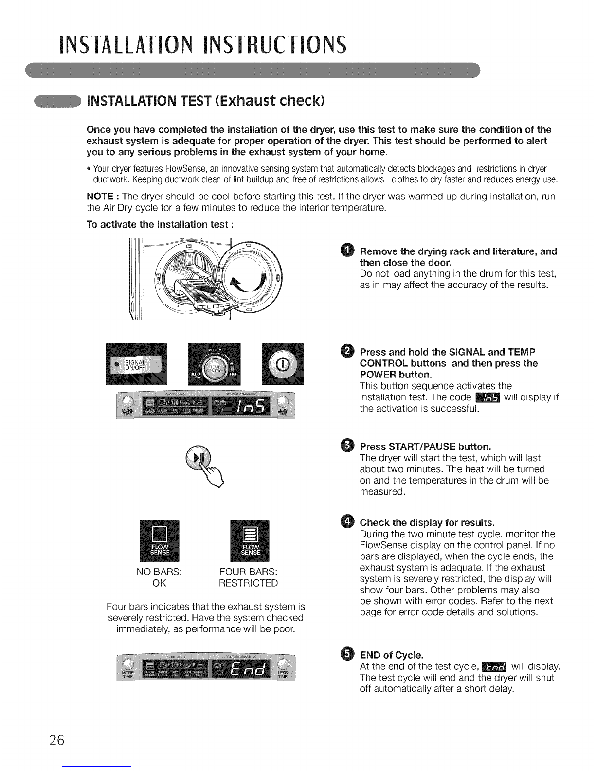
O Remove the drying rack and literature, and
then close the door.
Do not load anything in the drum for this test,
as in may affect the accuracy of the results.
O
Press and hold the SIGNAL and TEMP
CONTROL buttons and then press the
POWER button.
This button sequence activates the
installation test. The code _ will display if
the activation is successful.
O
Press START/PAUSE button.
The dryer will start the test, which will last
about two minutes. The heat will be turned
on and the temperatures in the drum will be
measured.
m
NO BARS:
OK
FOUR BARS:
RESTRICTED
Four bars indicates that the exhaust system is
severely restricted. Have the system checked
immediately, as performance will be poor.
O
Check the display for results.
During the two minute test cycle, monitor the
FIowSense display on the control panel. If no
bars are displayed, when the cycle ends, the
exhaust system is adequate. If the exhaust
system is severely restricted, the display will
show four bars. Other problems may also
be shown with error codes. Refer to the next
page for error code details and solutions.
O END of Cycle.
At the end of the test cycle, | will display.
The test cycle will end and the dryer will shut
off automatically after a short delay.
26

INSTA/[MION INST UcTIONS
INSTALLATION TEST (ExhauSt check)
• Check the Error Code before you call for service
Error Code Possible Causes , Solutions
• Temperature sensor failure
tel or rE2
HS • Humidity Sensor failure.
PS or PF or nP
• Electric dryer power cord is not con-
nected correctly, or house power
supply is incorrect.
• House fuse is blown, circuit breaker
has tripped, or power outage has oc-
curred.
• Turn off the dryer and call for
service.
• Turn off the dryer and call for
service.
Check the power supply or the
connection of power cord to
the terminal block. Refer to the
Connecting Electric Dryers
section of this manual for
complete instructions.
• Reset circuit breaker or replace
fuse.
Do not increase the fuse capacity.
If the problem is a circuit over-
load, have it corrected by a
qualified electrician.
• Check the duct condition
If the test displays four bars, check the exhaust system
for restrictions and damage. Repair or replace the
exhaust system as needed.
NOTE: When the dryer is first installed, this test should
be performed to alert you to any existing problems with
the exhaust duct in your home. However, since the
test performed during normal operation provides more
accurate information on the condition of the exhaust
duct than does the installation test, the number of bars
displayed during the two tests may not be the same.
IMPORTANT: Do not interrupt the test cycle, as this
could result in the wrong results.
NOTE: Even if no bars are displayed during the test
cycle, some restrictions may still be present in the
exhaust system. Refer to the Venting the Dryer section
of this manual for complete exhaust system and venting
requirements.
Restricted or Blocked Airflow []
Avoid long runs or runs with multiple
elbows or bends.
Excess or crushed
transition duct
Too many elbows
or exhaust too long
Check for blockages and lint buildup.
Lint
buildup or
blockage
Make sure the ductwork is not crushed
or restricted.
Crushed or
damaged exhaust
27
0 TO USE
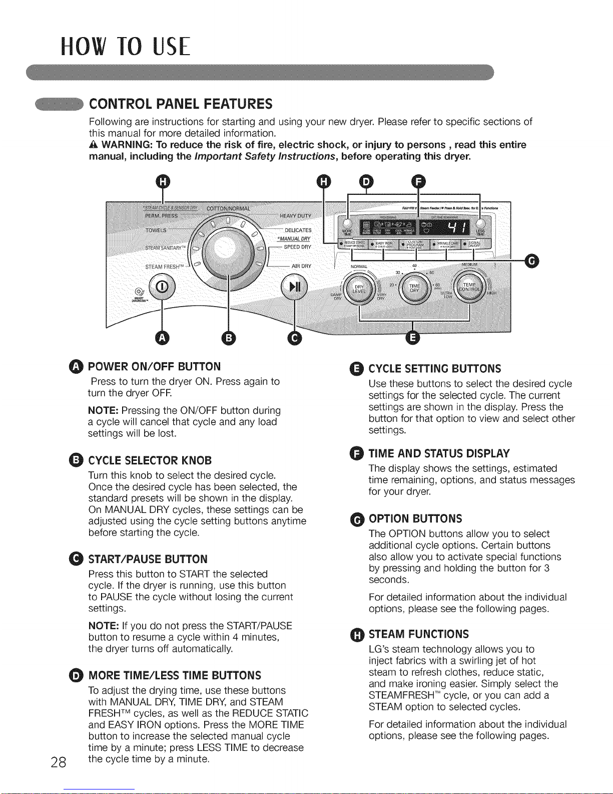
CONTROL PANEL FEATURES
Following are instructions for starting and using your new dryer. Please refer to specific sections of
this manual for more detailed information.
WARNING: To reduce the risk of fire, electric shock, or injury to persons, read this entire
manual, including the Important Safety Instructions, before operating this dryer.
O
28
O POWER ON/OFF BUTTON
Press to turn the dryer ON. Press again to
turn the dryer OFR
NOTE: Pressing the ON/OFF button during
a cycle will cancel that cycle and any load
settings will be lost.
Q
CYCLE SELECTOR KNOB
Turn this knob to select the desired cycle.
Once the desired cycle has been selected, the
standard presets will be shown in the display.
On MANUAL DRY cycles, these settings can be
adjusted using the cycle setting buttons anytime
before starting the cycle.
O
START/PAUSE BUTTON
Press this button to START the selected
cycle. If the dryer is running, use this button
to PAUSE the cycle without losing the current
settings.
NOTE: If you do not press the START/PAUSE
button to resume a cycle within 4 minutes,
the dryer turns off automatically.
O
MORE TIME/LESS TIME BUTTONS
To adjust the drying time, use these buttons
with MANUAL DRY, TIME DRY, and STEAM
FRESHTM cycles, as well as the REDUCE STATIC
and EASY IRON options. Press the MORE TIME
button to increase the selected manual cycle
time by a minute; press LESS TIME to decrease
the cycle time by a minute.
Q
e
O
CYCLE SETTING BUTTONS
Use these buttons to select the desired cycle
settings for the selected cycle. The current
settings are shown in the display. Press the
button for that option to view and select other
settings.
TIME AND STATUS DISPLAY
The display shows the settings, estimated
time remaining, options, and status messages
for your dryer.
OPTION BUTTONS
The OPTION buttons allow you to select
additional cycle options. Certain buttons
also allow you to activate special functions
by pressing and holding the button for 3
seconds.
For detailed information about the individual
options, please see the following pages.
STEAM FUNCTIONS
LG's steam technology allows you to
inject fabrics with a swirling jet of hot
steam to refresh clothes, reduce static,
and make ironing easier. Simply select the
STEAMFRESH TMcycle, or you can add a
STEAM option to selected cycles.
For detailed information about the individual
options, please see the following pages.
0
0
O
O
O
O
0
0
OW TO USE
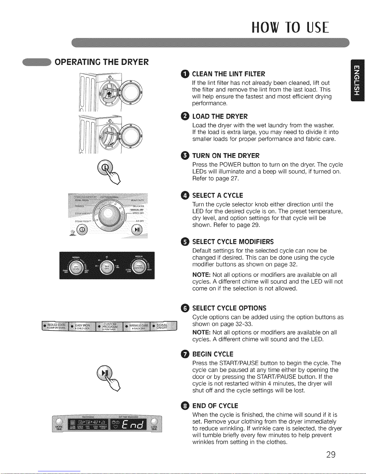
CLEAN THE LiNT FILTER
If the lint filter has not already been cleaned, lift out
the filter and remove the lint from the last load. This
will help ensure the fastest and most efficient drying
performance.
LOAD THE DRYER
Load the dryer with the wet laundry from the washer.
If the load is extra large, you may need to divide it into
smaller loads for proper performance and fabric care.
TURN ON THE DRYER
Press the POWER button to turn on the dryer. The cycle
LEDs will illuminate and a beep will sound, if turned on.
Refer to page 27.
SELECT A CYCLE
Turn the cycle selector knob either direction until the
LED for the desired cycle is on. The preset temperature,
dry level, and option settings for that cycle will be
shown. Refer to page 29.
SELECT CYCLE MODIFIERS
Default settings for the selected cycle can now be
changed if desired. This can be done using the cycle
modifier buttons as shown on page 32.
NOTE: Not all options or modifiers are available on all
cycles. A different chime will sound and the LED will not
come on if the selection is not allowed.
SELECT CYCLE OPTIONS
Cycle options can be added using the option buttons as
shown on page 32-33.
NOTE: Not all options or modifiers are available on all
cycles. A different chime will sound and the LED.
BEGIN CYCLE
Press the START/PAUSE button to begin the cycle. The
cycle can be paused at any time either by opening the
door or by pressing the START/PAUSE button. If the
cycle is not restarted within 4 minutes, the dryer will
shut off and the cycle settings will be lost.
END OF CYCLE
When the cycle is finished, the chime will sound if it is
set. Remove your clothing from the dryer immediately
to reduce wrinkling. If wrinkle care is selected, the dryer
will tumble briefly every few minutes to help prevent
wrinkles from setting in the clothes.
29
0 TO USE
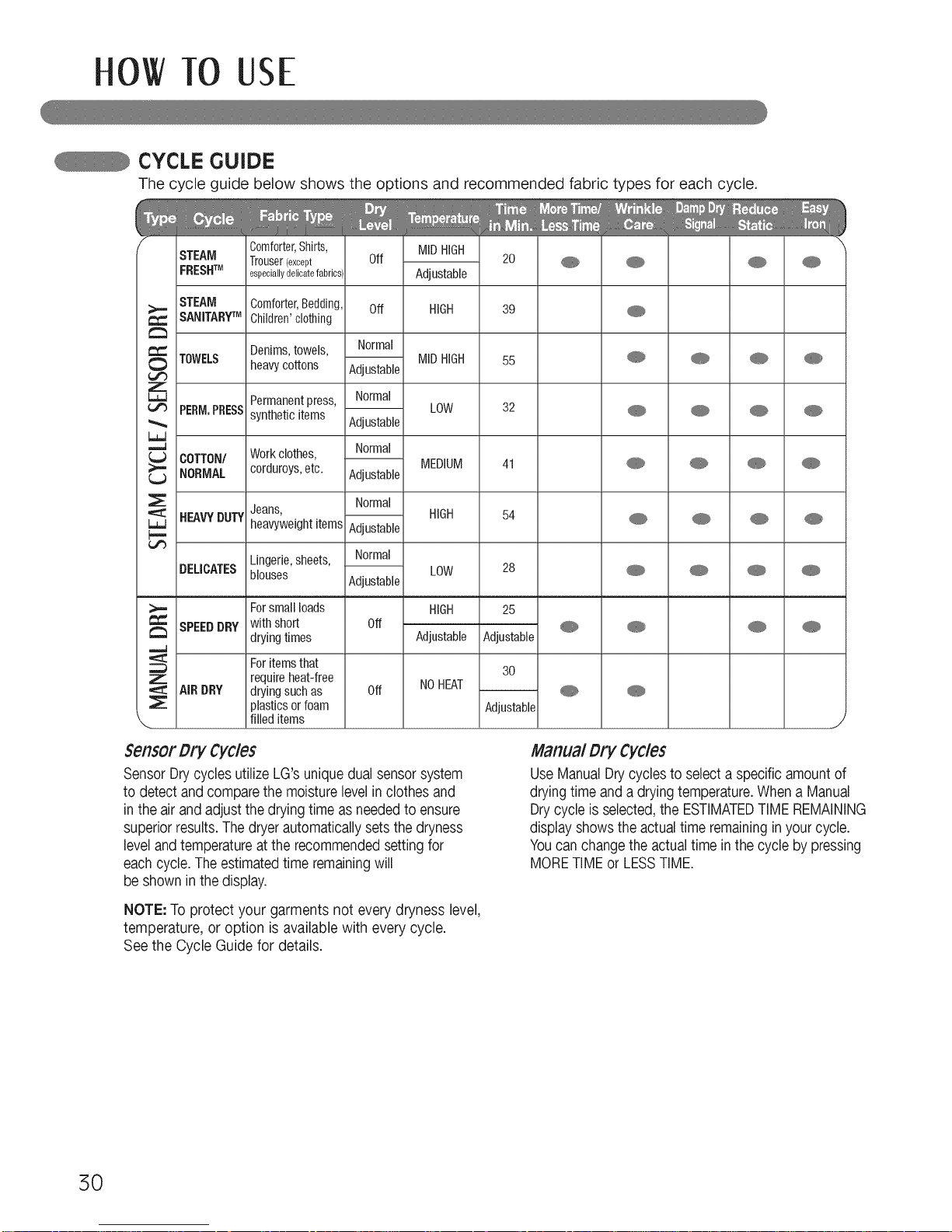
CYCLE GUIDE
The cycle guide below shows the options and recommended fabric types for each cycle.
Comforter,Shirts, MIDHIGH
STEAM Trouser(except Off 20 _
FRESHTM especiallydelicatefabrics', Adjustable
STEAM Comforter,Bedding, Off HIGH 39
SANITARYTM Children'clothing
Denims,towels, Normal
TOWELS heavycottons Adjustable MIDHIGH 55
Permanentpress, Normal
PERM.PRESSsyntheticitems Adjustable LOW 32
COTTON/ Workclothes, Normal
MEDIUM 41
NORMAL corduroys,etc. Adjustable
Normal
Jeans,
BEAVYDUTYheavyweightitems Adjustable
HIGH 54
Lingerie,sheets, Normal
DEUCATESblouses Adjustable LOW 28
Forsmall loads HIGH 25
SPEEDDRY with short Off _
drying times Adjustable Adjustable
For items that
require heat-free 30
AIR DRY drying such as Off NOHEAT _
plastics orfoam Adjustable
filled items
J
Sensor Dry Cycles
SensorDrycycles utilizeLG's uniquedual sensorsystem
to detect andcomparethe moisturelevelin clothes and
in the air andadjust the dryingtime as neededto ensure
superiorresults.The dryerautomaticallysets the dryness
levelandtemperatureat the recommendedsettingfor
eachcycle.The estimatedtime remainingwill
be shown in thedisplay.
NOTE: To protect your garments not every dryness level,
temperature, or option is availablewith everycycle.
See the Cycle Guide for details.
Manual Dry Cycles
UseManualDrycyclesto selecta specific amountof
dryingtime and a dryingtemperature.Whena Manual
Drycycle is selected,the ESTIMATEDTIMEREMAINING
display showsthe actual time remaininginyourcycle.
Youcanchange the actualtime inthe cycle by pressing
MORETIMEor LESSTIME.
5O
 Loading...