

LG DLEX0001TM, DLGX0002TM, DLEX2501 Series, DLGX2502 Series Service Manual

U.S.A. Website: http://us.lgservice.com
Canadian Website: http://lg.ca
ELECTRIC & GAS DRYER
SERVICE MANUAL
CAUTION
READ THIS MANUAL CAREFULLY IN ORDER TO
PROPERLY DIAGNOSE PROBLEMS AND TO SAFELY
PROVIDE QUALITY SERVICE ON THESE DRYERS.
MODEL : DLEX0001TM / DLGX0002TM

November 2007 PRINTED IN KOREA
P/No. : 3828EL3005P
2
To avoid personal injury, disconnect power before servicing this product. If electrical power is required
for diagnosis or test purposes, disconnect the power immediately after performing the necessary checks.
!
WARNING !
WHAT TO DO IF YOU SMELL GAS:
IMPORTANT SAFETY NOTICE
The information in this service guide is intended for use by individuals possessing skill and experience in
electrical, electronic, and mechanical appliance repair. Any attempt to repair a major appliance may result
in personal injury and property damage. The manufacturer or seller cannot be responsible for the
interpretation of this information, nor can it assume any liability in connection with its use.
RECONNECT ALL GROUNDING DEVICES
If grounding wires, screws, straps, clips, nuts, or washers used to complete a path to ground are
removed for service, they must be returned to their original position and properly fastened.
IMPORTANT
Electrostatic Discharge (ESD)
Sensitive Electronics
ESD problems are present everywhere. ESD may damage or weaken the electronic
control assembly. The new control assembly may appear to work well after repair is
finished, but failure may occur at a later date due to ESD stress.
■
Use an anti-static wrist strap. Connect wrist strap to green ground connection point or unpainted
metal in the appliance.
- OR -
Touch your finger repeatedly to a green ground connection point or unpainted metal
in the appliance.
■
Before removing the part from its package, touch the anti-static bag to a green ground connection
point or unpainted metal in the appliance.
■
Avoid touching electronic parts or terminal contacts; handle electronic control assembly by edges only.
■
When repackaging failed electronic control assembly in anti-static bag, observe above instructions.
■ Do not try to light a match, or cigarette, or turn on
any gas or electrical appliance.
■ Do not touch any electrical switches. Do not use any
phone in your building.
■ Clear the room, building or area of all occupants.
■ Immediately call your gas supplier from a neighbor’s
phone. Follow the gas supplier’s instructions
carefully.
■ If you cannot reach your gas supplier, call the fire
department.

CONTENTS
1. SPECIFICATIONS ...............................................................................................................4
2. FEATURES AND BENEFITS .............................................................................................. 6
3. INSTALLATION INSTRUCTIONS ....................................................................................... 6
4. DRYER CYCLE PROCESS .............................................................................................. 13
5. COMPONENT TESTING INFORMATION ........................................................................ 14
6. MOTOR DIAGRAM AND SCHEMATIC ............................................................................. 17
7. CONTROL LAYOUT .......................................................................................................... 18
8. WIRING DIAGRAM ........................................................................................................... 19
9. STEAM FUNCTION .......................................................................................................... 20
9-1. STEAM CYCLE GUIDE .............................................................................................. 20
9-2. TROUBLESHOOTING FOR STEAM DRYER ........................................................... 21
9-3. DISPLAY FAULT/ERROR CODES FOR STEAM DRYER ......................................... 21
10. FLOW SENSOR FUNCTION ........................................................................................... 22
10-1. FLOW SENSOR ..................................................................................................... 22
10-2. INSTALLATION CHECK ........................................................................................ 23
10-3. TROUBLESHOOTING FOR FLOW SENSOR DRYER .......................................... 24
11. DIAGNOSTIC TEST ......................................................................................................... 25
11-1. TEST 1 120V AC ELECTRICAL SUPPLY ............................................................. 27
11-2. TEST 2 THERMISTOR TEST ............................................................................... 29
11-3. TEST 3 MOTOR TEST .......................................................................................... 30
11-4. TEST 4 MOISTURE SENSOR .............................................................................. 31
11-5. TEST 5 DOOR SWITCH TEST ............................................................................. 32
11-6. TEST 6 HEATER SWITCH TEST - ELECTRIC MODEL ....................................... 33
11-7. TEST 7 GAS VALVE TEST - GAS MODEL ........................................................... 34
11-8. TEST 8 SEMI-CONDUCTOR ................................................................................ 35
11-9. TEST 9 MOTOR ASSEMBLY, DC, PUMP ............................................................ 35
11-10. TEST 10 GENERATOR ASSEMBLY ................................................................... 36
12. CHANGE GAS SETTING (NATURAL GAS, PROPANE GAS) ....................................... 37
13. DISASSEMBLY INSTRUCTIONS .................................................................................... 39
14. EXPLODED VIEW ........................................................................................................... 48
14-1. CONTROL PANEL & PLATE ASSEMBLY ............................................................... 48
14-2. PANEL DRAWER ASSEMBLY & GUIDE ASSEMBLY ............................................. 49
14-2-1. CABINET & DOOR ASSEMBLY: ELECTRIC MODEL .......................................... 50
14-2-2. CABINET & DOOR ASSEMBLY: GAS MODEL .................................................... 51
14-3-1. DRUM & MOTOR ASSEMBLY: ELECTRIC MODEL ............................................ 52
14-3-2. DRUM & MOTOR ASSEMBLY: GAS MODEL ...................................................... 53
3
44
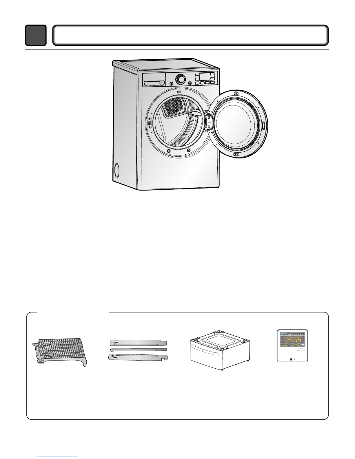
SPECIFICATIONS
1
■ Name: Electric and Gas Dryer
■ Power supply: Please refer to the rating label regarding detailed
information.
■ Size: 27 X 29.9 X 38.7 (inch)
■ Dryer capacity: IEC 7.3 cu.ft.
■ Weight: 131(Ibs)
❋ Specifications are subject to change by manufacturer.
■ ACCESSORIES
Dryer rack (1 each) Stacking kit (1 each)
Purchased Separately
Pedestal (1 each)
Purchased Separately
See page 6 See page 7 See page 8
Remote Laundry Monitor
Purchased Separately
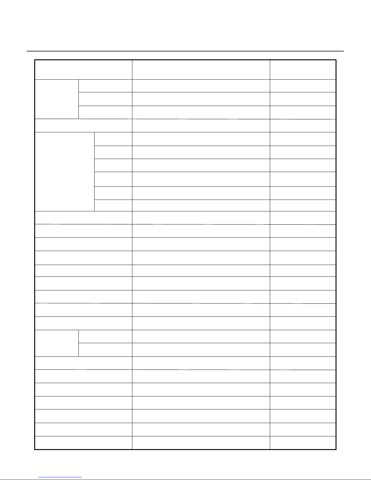
5
Temperature
Moisture
On/Off
Sensor
5
131/158
Door Trim
Top Plate
Color
Chromate
STS
Natural
120V/240V 60Hz (26A)
POWER SUPPLY
LAMP
HEATER
MOTOR
3
9
7.3 cu.ft.
Electronic
GAS VALVE
5400W (22.5A)
5
250W (4.5A)
15 W (0.2A)
13 W (110mA) x 2
ELECTRICITY
CONSUMPTION
Material &
Finish
ITEM
Child Lock
Reversible Door
Interior Light
Product (WxHxD)
Packing (WxHxD)
Sound levels
Dryer Rack
Drum
No. of Dry Levels
No. of Dry Options
No. of Programs
2No. of Steam Options
DRUM CAPACITY
CONTROL TYPE
No. of Temperature Controls
Weight (lbs) - Net/Gross
AC 120V
AG HEATER
1100W (9.2A)
AC 120V(STEAM MODEL)
DC, PUMP
1.7W (0.15A)
ADC 12V(STEAM MODEL)
(GAS MODEL)
AC 240V (ELECTRIC MODEL)
Electrode sensor
Thermistor
AC 120V
AC 120V
REMARK
DLEX0001TM
DLGX0002TM
Available
Available
Available
Available
Avaiable
Avaiable
27" x 42 3/4" x 28 1/3"
29 1/2" x 44 3/4" x 30 3/4"
Stainless Steel
6
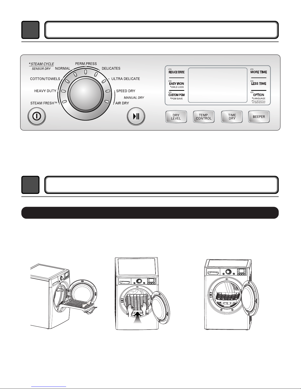
FEATURES AND BENEFITS
2
INSTALLATION INSTRUCTIONS
3
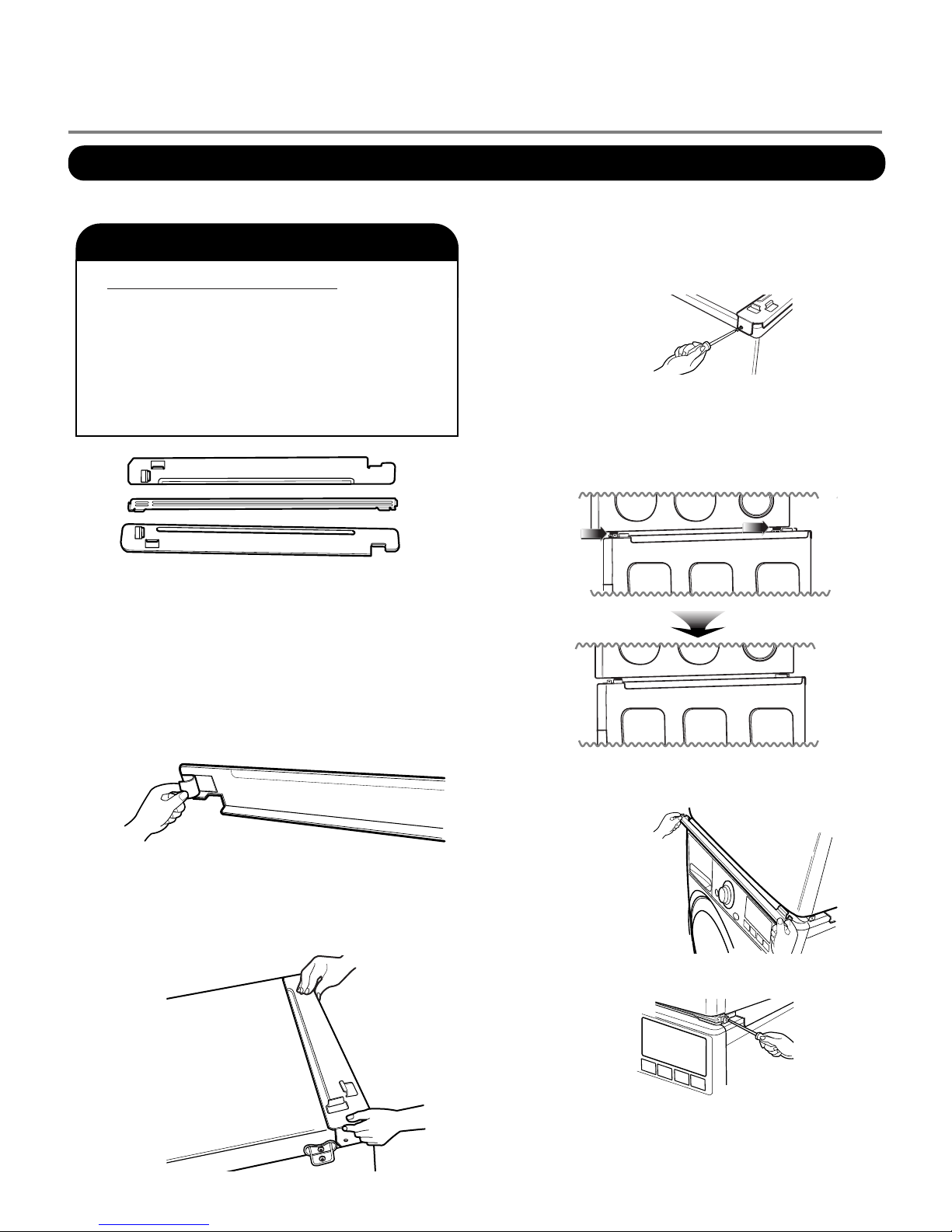
Open the door.
Hold the dryer rack
with both hands.
Put the dryer rack into
the drum
Check and be sure that the
front of the rack is properly
seated behind the lint filter.
1
23
Dryer Rack Installation Instructions
7
To ensure safe and secure installation, please observe the instructions below.
Place the washer firmly on a stable, even
and solid floor as product installation
instructions describe in the owner’s
manual.
Peel the protective paper from the tape on
the side bracket.
Fit the side bracket firmly to the side of the
top plate by attaching the double-faced tape
to the top plate as picture shown.
Secure the side bracket to the washer with
a screw on the back of the bracket. Repeat
Steps 2, 3, & 4 for the other side.
Place the dryer on top of the washer by
placing the legs as shown. Be careful not to
pinch fingers between the washer and dryer.
Slide the dryer back against the stop on the
side rail.
Insert the front rail of the stacking kit. Push
the front rail back against the stops on the
side brackets.
• Do not use a stacking kit with a gas dryer in
potentially unstable conditions like a mobile
home.
Stacking kit
Do not attempt this alone!
At least two people are required to lift and
position the dryer on top of a washing
machine!
Failure to heed this warning can result in
serious physical injury and damage to the
appliance.
WARNING
1
2
3
4
5
6
7
Stacking Kit Installation Instructions
Screw both sides of the front rail to the side
brackets.
8
※※
For washer, dryer, and combo LG 27”
25 3/8
?
(64.5cm)
2.86
?
(7cm)
18 3/4
(47.5 cm)
27
?
(68.6cm)
7 1/4
(18.4cm)
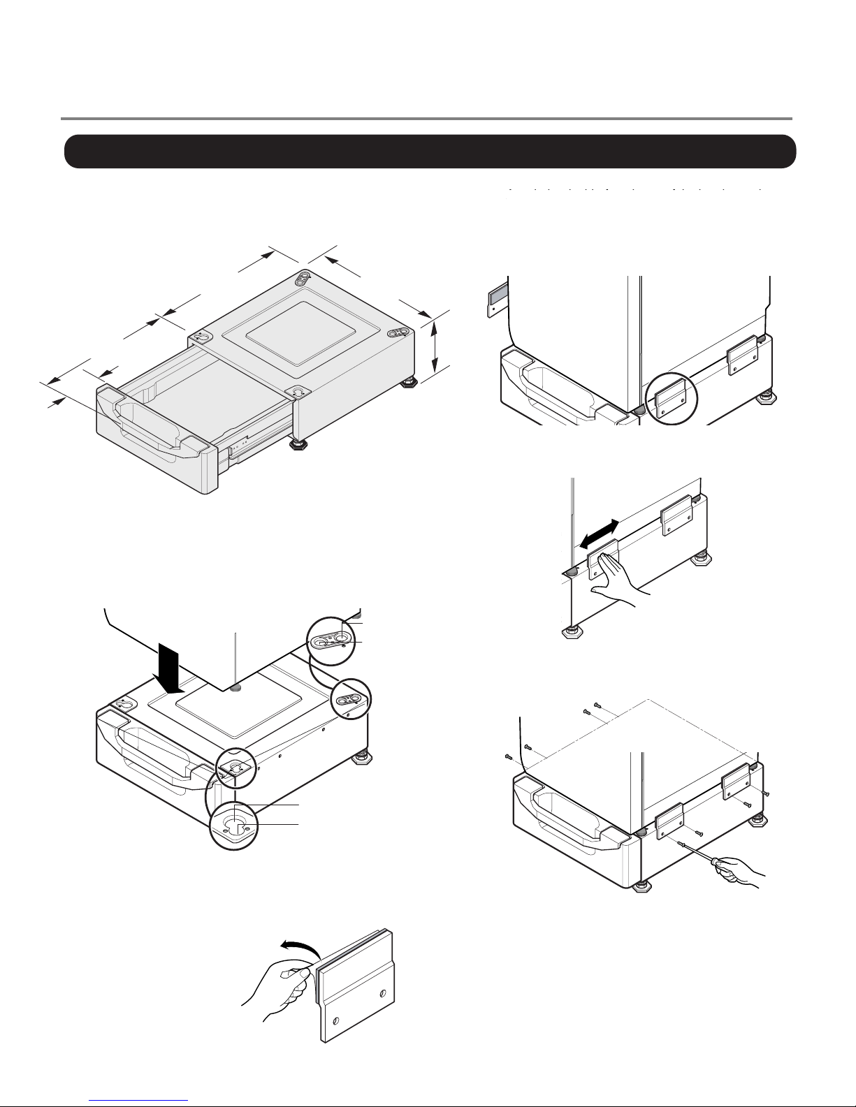
Pedestal Installation Instructions
4
Attach the double-faced tape of the bracket to the
dryer as shown so the bent parts of the brackets
align with the edge and can be attached to the
pedestal with screws.
NOTE :
Attach the lower side first.
5
Be sure to press the adhesive parts of the brackets
firmly to the appliance.
6
Install the eight (8) screws(supplied) to attach the
brackets to the pedestal.
7
Move the dryer to the desired place.
NOTE :
The appliance and pedestal assembly
must be placed on a solid and level floor
for proper operation. Adjust the legs of the
appliance and pedestal by turning with a
wrench. Then, adjust the lock unt toward
the pedestal while holding the pedestal leg
using a wrench.
1
Remove pedestal, installation hardware, and
instructions from the shipping carton.
2
Position the dryer on top of the pedestal.
,
.
3
Remove the paper from the
bracket.
for washer/
combo
for washer/
combo
for dryer
for dryer
NOTE: That the Pedestal
hardware packet may include 2 sets of side
brackets. Be sure to use
the brackets marked for
the dryer.
After removing the protective covering from the
adhesive surface, align the screw holes in the
brackets with the matching holes in the pedestal
base and press and press the brackets against
the base and the dryer.
9
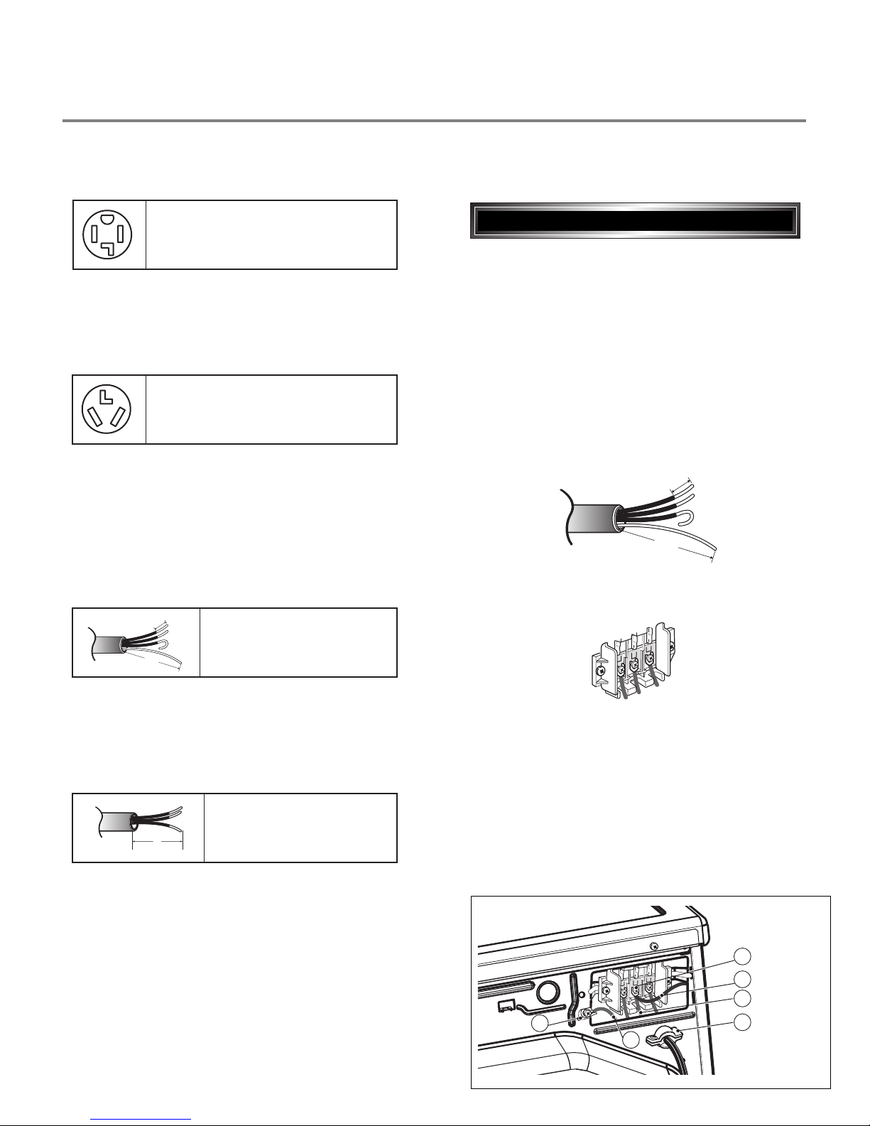
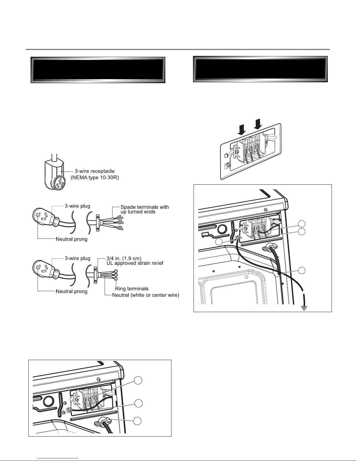
Use the instructions under option 2 or 3 if your
home has a 3-wire receptacle (NEMA type 10-30R).
Use option 2 if local codes and ordinances permit
the connection of a chassis ground to the neutral
connector. If this is not permitted, use option 3.
Review the following options to determine the appropriate electrical connection for your home:
Electric Dryer Only
If this type is available at your home. you will be
connecting to a fused disconnect or circuit breaker
box
Important : Grounding through the neutral conductor
is prohibited for (1) new branch-circuit installations,
(2) mobile homes, and (3) recreational vehicles, and
(4) areas where local codes prohibit grounding through
the neutral conductor.
Prepare minimum 5ft(1.52m) of length in order for
dryer to be replaced.
First, peel 5 inch (12.7cm) of covering material from
end. Make a 5 inch of ground wire bared. After cutting
1
1
/2 inch (3.8cm) from 3 other wires. peel insulation
back 1inch (2.5cm). Make ends of 3 wires a hook
shape.
Then, put the hooked shape end of the wire under the
screw of the terminal block(hooked end facing rightward)
and pinch the hook together and screw tightly.
Use the instructions under option 1 if your home
homehas a 4-wire receptacle (NEMA type 14-30R).
If this type is available at your home. you will be
connecting to a fused disconnect or circuit breaker
box
1. Connect neutral wire(white) of power cord to center
terminal block screw.
2. Connect red and black wire to the left and right
terminal block screws.
3. Connect ground wire(green) of power cord to external
ground screw and move neutral ground wire of
appliance and connect it to center screw.
4. Make sure that the strain relief screw is tightened.
and be sure that all terminal block nuts are on tight and
power cord is in right position.
5"
(12.7 cm)
3
1
/
2
"
(8.6 cm)
1"
(2.5 cm)(2.5 cm)
5"
(12.7 cm)(12.7 cm)
1"
(2.5 cm)
3V
2
"
(8.9 cm)
3-wire direct
4-wire receptacle
(NEMA type14-30R)
3-wire receptacle
(NEMA type10-30R)
4-wire direct
5"5"
(12.7 cm)(12.7 cm)
3
1
/
2
"
(8.6 cm)
4-wire connection : Direct wire
5"
(12.7 cm)
3
1
/
2
"
(8.6 cm)
1"1"
(2.5 cm)(2.5 cm)
5"
(12.7 cm)(12.7 cm)
1"
(2.5 cm)
3V
2
"
(8.9 cm)
F
a
b
E
D
C
10
Important : Grounding through the neutral conductor
is prohibited for (1) new branch-circuit installations,
(2) mobile homes, and (3) recreational vehicles, and
(4) areas where local codes prohibit grounding through
the neutral conductor.
Prepare minimum 5ft(1.52m) of length in order for
dryer to be replaced.
First, peel 3
1
/2 inch (8.9cm) of covering material
from end and bare 1 inch from the ends.
1. Connect neutral wire(white) of power cord to
center terminal block screw.
2. Connect red and black wire to the left and right
terminal block screws.
3. Make sure that the strain relief screw is tightened
and be sure that all terminal block nuts are on
tight and power cord is in right position.
Then, put the hooked shape end of the wire under
the screw of the terminal block(hooked end facing
rightward) and pinch the hook together and screw
tightly.
1"
(2.5 cm)
3V3V
2
"
(8.9 cm)(8.9 cm)
3-wire connection : Direct wire
1. Connect the neutral wire (white) of the power
cord to the center terminal block screw.
2. Connect the red and black wires to the left and
right terminal block screws.
3. Connect the ground wire (green) of the power
cord to the external ground screw. Remove the
neutral ground wire of appliance and connect it to
center screw.
4. Make sure that the strain relief screw is tightened
and that all terminal block nuts are tight and the
power cord is in the right position.
F
a
b
E
D
C
• lf your local codes or ordinances do not allow the
use of a 3 wire connection, or you are installing
your dryer in a mobile home, you must use a 4wire connection.
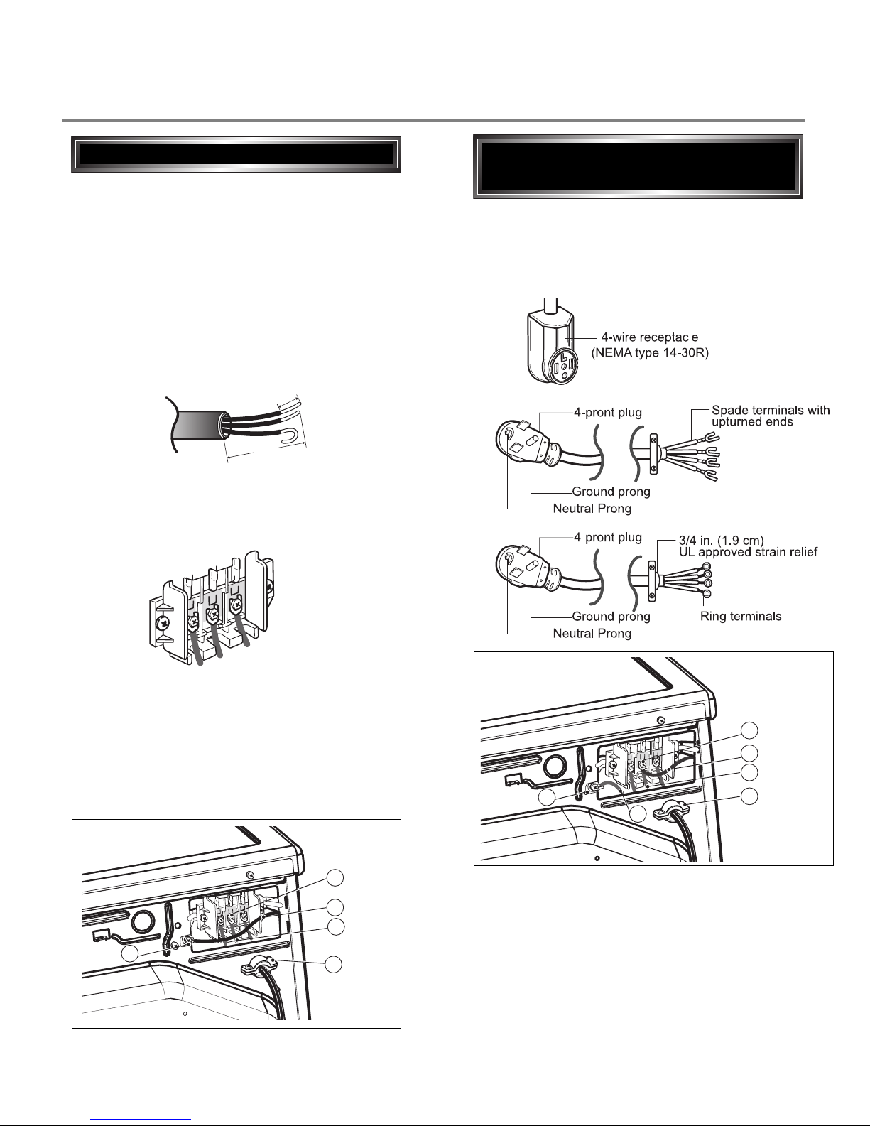
Option 1: 4-wire connection with
a Power supply cord.
E
a
D
B
C
11
1. Remove the appliance ground wire (D) (green)
fromthe external ground connector screw and
reconnect it, together with the center, white,
neutral wire (E) to the center, silver colored,
terminal block screw.
2. Connect the other two power cord wires (red and
black) to the left and right terminal block screws
and tighten securely.
3. Tighten the strain relief screws securely.
4. Connect an independent ground wire (F) from the
external ground connector screw to a proper
ground. (The ground wire must be long enough to
allow the appliance to be moved, if necessary, for
service or cleaning.)
C
B
A
lf your local codes or ordinances permit the
connection of a frame-grounding conductor to the
neutral wire, use these instructions. If your local
codes or ordinances do not allow the connection of
a frame-grounding conductor to the neutral wire,
use the instructions under Section 3: Optional
3-wire connection.
1. Connect the neutral (white or center) wire (B) to
the center, silver colored, screw (A) and tighten
securely.
2. Connect the other two power cord wires (red and
black) to the left and right terminal block screws
and tighten securely.
3. Tighten the strain relief screws (C) securely.
Option 2: 3-Wire Connection with
a Power Supply Cord
• If your local codes or ordinances do not allow the
connection of a frame-grounding conductor to the
neutral wire, use the instructions under this
section.
E
A
D
F
Option 3: Optional 3-wire
connection.
12
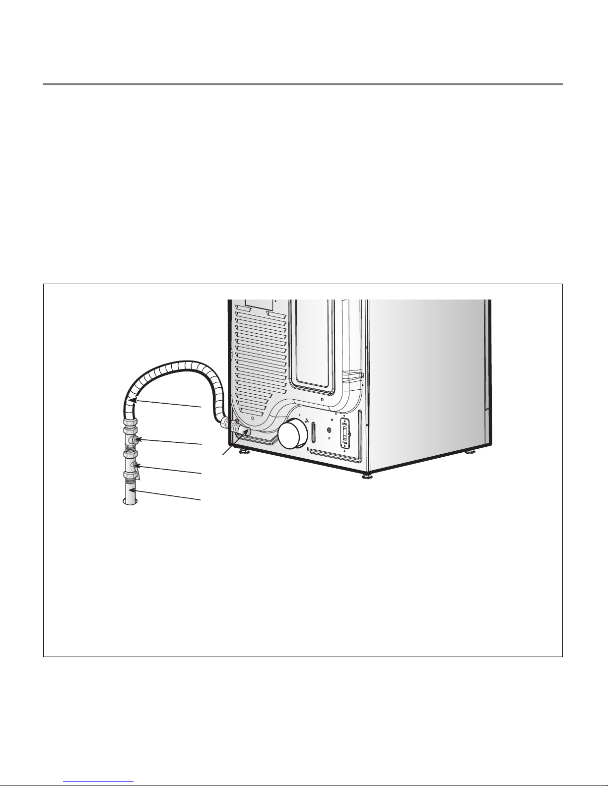
3-2. Connect Gas Supply Pipe (Gas Dryer ONLY)
1. Make certain your dryer is equipped for use with the
type of gas in your laundry room. Dryer is equipped
at the factory for Natural Gas with a 3/8” N.P.T. gas
connection.
2. Remove the shipping cap from the gas connection
at the rear of the dryer. Make sure you do not
damage the pipe thread when removing the cap.
3. Connect to gas supply pipe using a new flexible
stainless steel connector.
4. Tighten all connections securely. Turn on gas and
check all pipe connections (internal & external) for
gas leaks with a non-corrosive leak detection fluid.
5. For L.P. (Liquefied Petroleum) gas connection, refer
to section on Gas Requirements.
For further assistance, refer to section on Gas Requirements.
1 New Stainless Steel Flexible Connector - Use
only if allowed by local codes (Use Design
A.G.A. Certified Connector)
2 1/8” N.P.T. Pipe Plug
(for checking inlet gas pressure)
3 Equipment Shut-Off Valve-Installed within 6’
(1.8 m) of dryer
4 Black Iron Pipe
Shorter than 20’ (6.1 m) - Use 3/8” pipe
Longer than 20’ (6.1 m) - Use 1/2” pipe
5 3/8” N.P.T. Gas Connection
2
3
5
1
4
13
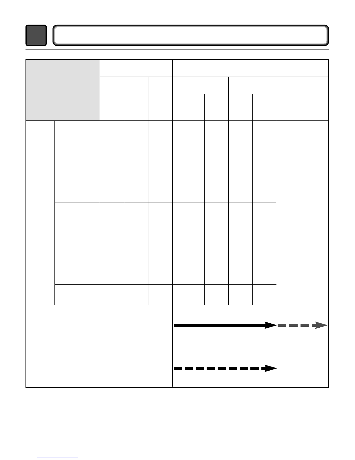
DRYER CYCLE PROCESS
4
Time
Cycle
HEAVY DUTY
3Hr
3Hr
Off Time: 6min
On Time: 10sec
Temperature Control for each cycle
HIGH
MID
HIGH
MEDIUM
LOW
LOW
ULTRA
LOW
MID
HIGH
(HIGH)
COTTON/
TOWELS
NORMAL
PERM
PRESS
DELICATES
ULTRA
DELICATE
STEAM
FRESH
SPEED DRY
AIR DRY
-
(Normal)
(Normal)
(Normal)
(Normal)
(Normal)
(Normal)
(Normal)
-
-
54min Saturation
Saturation
Saturation
Saturation
Saturation
Saturation
Saturation
Saturation
55min
41min
36min
32min
34min34min
20min
25min
30
min
(5min)
(5min)
(5min)
(5min)
(5min)
(5min)
(1min)
(5min)
N/A
68±4°C
66±4°C
60±4°C
52±3°C
52±3°C
45±3°C
60±4°C
(70±5°C)
No
heater
47±5°C
47±5°C
47±5°C
47±5°C
38±5°C
38±5°C
47±5°C
(47±5°C)
N/A
Saturation
Load
Sensor
Dry *
Manual
Dry **
Default
Drying
Electro-
sensor
Temp-
Control
Default
time
Temp-
Control **
Cooling Wrinkle care
Conditions of operation and termination
Temp-
erature
Dry
Level
Display
time
Motor
Heater
* Sensor dry : “Dry Level” is set by users.
** Manual dry : “Temperature control” is set by users.
Default settings can be adjusted by users.
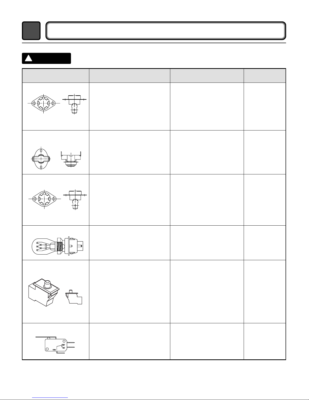
14
When checking the Component, be sure to turn the power off, and do voltage discharge sufficiently.
COMPONENT TESTING INFORMATION
5
!
CAUTION
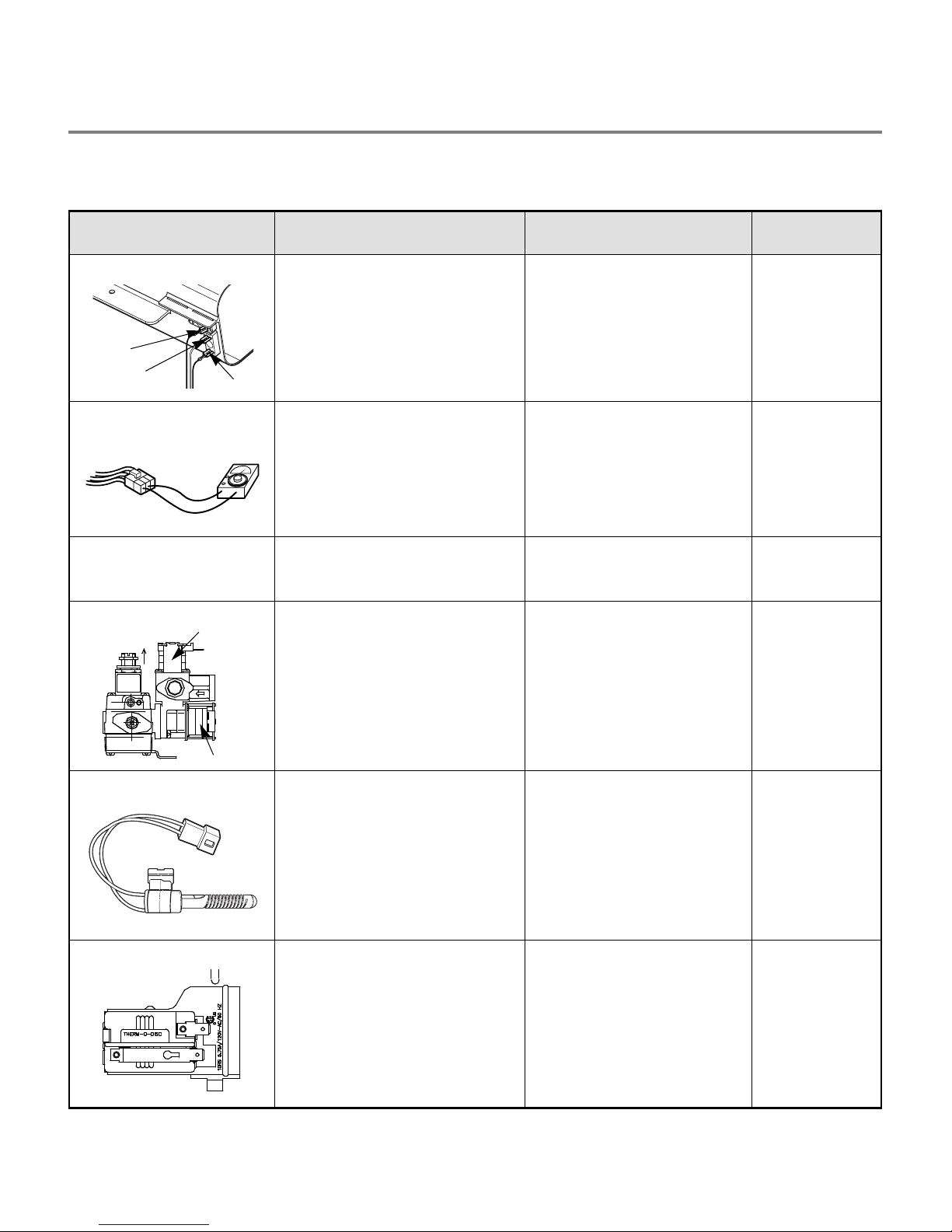
Component Test Procedure Check result Remark
1. Thermal cut off
• Check Top Marking:
N130
Measure resistance of terminal
to terminal
Open at 266±12°F
(130±7°C)
Auto reset 31°F (35°C)
Same shape as Outlet Thermostat.
If thermal fuse is open must
be replaced
Resistance value ≒∞
Continuity (250°F ↓) < 1Ω
• Heater case-
Safety
• Electric type
2. Hi limit Thermostat
(Auto reset)
Measure resistance of terminal
to terminal
Open at 257±9°F
(125±5°C)
Close at 221±9°F
(105±5°C)
Resistance value ≒∞
Resistance value < 5Ω
• Heater case Hi limit
• Electric type
3. Outlet Thermostat
( Auto reset)
• Check Top Marking:
N85
Measure resistance of terminal
to terminal
Open at 185±9°F
(85±5°C)
Close at 149±9°F
(65±5°C)
Same shape as Thermal cut off.
Resistance value ≒∞
Resistance value < 5Ω
• Blow housing Safety
• Electric type
4. Lamp holder Measure resistance of terminal
to terminal
Resistance value:
80Ω ~ 100Ω
6. Idler switch Measure resistance of the
following terminal:
“COM - NC”
1. lever open
Resistance value < 1Ω
2. Lever push (close)
Resistance value ≒∞
5. Door switch Measure resistance of the
following terminal
1) Door switch knob: open
Terminal: “COM” - “NC” (1-3)
Terminal: “COM” - “NO” (1-2)
2) Door switch push: push
Terminal: “COM” - “NC” (1-3)
Terminal: “COM” - “NO” (1-2)
Resistance value < 1Ω
Resistance value ≒∞
Resistance value ≒∞
Resistance value < 1Ω
The state that
Knob is
pressed is
opposite to
Open
condition.
15
Component Test Procedure Check result Remark
7. Heater Measure resistance of the
following terminal
Terminal: 1 (COM) - 2
Terminal: 1 (COM) - 3
Terminal: 2 - 3
Resistance value: 10Ω
Resistance value: 10Ω
Resistance value: 20Ω
• Electric type
8. Thermistor Measure resistance of terminal
to terminal
Temperature condition:
58°F ~ (10~40°C)
58°F ~ 104F (10~40°C)
Resistance value: 10Ω • Heater case -
Hi limit
• Electric type
9. Motor • See Page 13
10. Gas valve
valve 1
valve 2
Measure resistance of the
following terminal
Valve 1 terminal
Valve 2 terminal
Resistance value: > 1.5 kΩ
Resistance value: >
1.5~2.5 kΩ
• Gas type
11. Igniter Measure resistance of terminal
to terminal
Resistance value: 100~800Ω • Gas type
12. Frame Detect Measure resistance of terminal
to terminal
Open at 370°F ((Maximum)
Close at 320°F
Resistance value ≒∞
Resistance value < 1Ω
• Gas type

16
Component Test Procedure Check result Remark
13. Outlet Thermostat
(Auto reset)
• Check Top Marking:
N95
Measure resistance of terminal
to terminal
Open at 203±7°F (95±5°C)
Close at 158±9°F (70±5°C)
Resistance value ≒∞
Continuity < 1Ω
• Gas type
• Gas funnel
14. Outlet Thermostat
(Manual reset)
• Check Top Marking:
N100
Measure resistance of terminal
to terminal
Open at 212±12°F
(100±7°C)
Manual reset
If thermal fuse is open must
be replaced
Resistance value ≒∞
Continuity < 1Ω
• Gas type
• Gas funnel
 Loading...