

LG DLG9588WM, DLG9588SM, DLE9577SM Owner’s Manual
ElectricandGasDryer
DLE9577WIVl / DLG9588WIVl
as it provides instructions
Maintenance.
and retain the
at http://us.lge.com
iiiiiiiin
P/No.: 3828EL3003M
OUTSTANDING PERFORMANCE
Not to mention unmatched big capacity, you can benefit from good
time efficiency, quiet operation and energy saving system.
STAINLESSSTEELDRUM
Stainless steel drum doesn't generate any rust.
ARTISTICDESIGN
Modern front panel look and big crystal-clear glass door make your dryer look stylish.
DIGITALFABRICCARE
Multi-Level temperature control takes better care of your clothes
make operating the dryer easy.
USING THE RIM (REMOTE LAUNDRY MONITOR)
The RLM monitors status of your dryer. You can plug the display unit into any power outlet in your
home. The RLM Display Unit can be purchased separately for this dryer.
Your dryer provides sensor drying and time drying programs.
Sensor Dry : Dryer electronically sense laundry humidity and it automatically determines operation time based on the
dryness of the load and the selected program. At times, you can see sudden increase or decrease in operation time.
It happens because a sensor will detect laundry humidity within a certain period. Sudden change in operation time is not a
malfunction.
Time Dry : You can manualy set drying time to complete drying. Use dry performance if clothes are still damp after
sensor dry cycle is finished. Time Dry is more effective for heavyweight and bulky items such as king-size bed sheets and
thick work clothes.
PART1. SPECIFICATIONS .................................................................................................................................................................................................................. 3
PART2. IMPORTANT WARRANTY AND SAFETY INSTRUCTIONS .............................................................................................................................................. 4-6
PART& INITIAL STEPS FOR INSTALLING YOUR DRYER .......................................................................................................................................................... 7-14
PART4. ACCESSORIES INSTALLATION .................................................................................................................................................................................... 15-16
PART5. ELECTRICAL REQUIREMENTS FOR ELECTRIC DRYER ............................................................................................................................................. 17-20
PART& ELECTRICAL REQUIREMENTS FOR GAS DRYERS .......................................................................................................................................................... 21
PART7. GAS REQUIREMENTS AND INSTRUCTIONS ..................................................................................................................................................................... 22
PART& EXHAUST REQUIREMENTS AND MAINTENANCE ....................................................................................................................................................... 23-24
PARTg. OPERATING YOUR DRYER ............................................................................................................................................................................................ 25-30
PART10. TROUBLESHOOTING GUIDE ........................................................................................................................................................................................ 31-33
LG DRYER LIMITED WARRANTY ...................................................................................................................................................................................................... 34
J
2
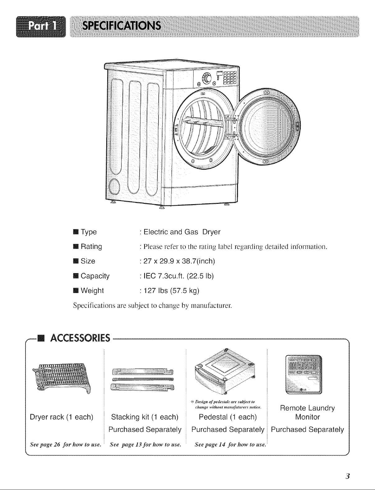
[] Type
Electric and Gas Dryer
[] Rating
[] Size
[] Capacity
[] Weight
Specifications are subject to change by manufacturer.
ACCESSORIES
Dryer rack (1 each)
Please refer to the rating label regarding detailed information.
27 x 29.9 x 38.7(inch)
IEC 7.3cu.ft. (22.5 Ib)
: 127 Ibs (57.5 kg)
Stacking kit (1 each)
_': Design of pedestals are subject to
ehange without manafaturers notice.
Pedestal (1 each)
Remote Laundry
Monitor
See page 26 for how to use.
Purchased Separately
See page 13 for how to use. See page 14 for how to use.
Purchased Separately
Purchased Separately
3
SEEKING WARRANTY ASSISTANCE
The Warranty for your Dryer is located at the end of this manual. Warranty Service is
available by contacting your nearest LG Service Center. If this product is installed and
operated per this manual, LG will repair or replace any parts defective in material or
workmanship throughout the Warranty period, beginning the Date of Purchase.
RNING!
For your safety_ the recommendations in this manual must be followed. To reduce the risk
of fire or explosion, electric shock or to prevent property damage, personal injury, or death
when using your appliance follow basic precautions, including the following.
Warranty Restriction: If the dryer is subjected to other than private family use, all warranty
coverage is effective for only 90 days.
You will need the complete Model and Serial Number when requesting Warranty Service. Proof of
purchase date is required.
Use the space below to record the model number and serial number of your new LG dryer.
Model No.
Serial No.
Date of Purchase
-_ Staple your receipt HERE.
J
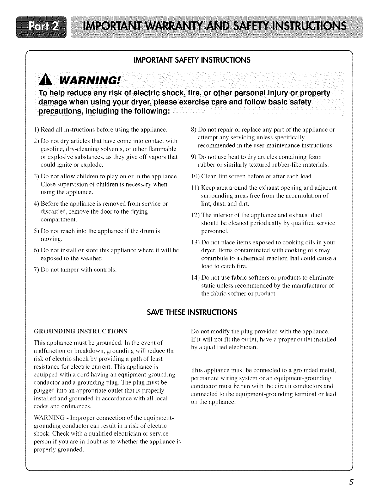
IMPORTANT SAFETY INSTRUCTIONS
WARNING!
To help reduce any risk of electric shock, fire, or other personal injury or property
damage when using your dryer, please exercise care and follow basic safety
1) Read all instructions before using the appliance.
2) Do not dry articles that have come into contact with
gasoline, dry-cleaning solvents, or other flammable
or explosive substances, as they give oft vapors that
could ignite or explode.
3) Do not allow children to play on or in the appliance. 10)
Close supervision of children is necessary when 11)
using the appliance.
4) Before the appliance is removed from service or
discarded, remove the door to the drying
compartment.
5) Do not reach into the appliance if the drum is
moving.
6) Do not install or store this appliance where it will be
exposed to the weather.
7) Do not tamper with controls.
8) Do not repair or replace any part of the appliance or
9) Do not use heat to dry articles containing foam
12) The interior of the appliance and exhaust duct
13) Do not place items exposed to cooking oils in your
14) Do not use fabric softners or products to eliminate
SAVETHESE INSTRUCTIONS
attempt any servicing unless specifically
recommended in the user-maintenance instructions.
rubber or similarly textured rubber-like materials.
Clean lint screen before or after each load.
Keep area around the exhaust opening and adjacent
surrounding areas fiee fiom the accumulation of
lint, dust, and dirt.
should be cleaned periodically by qualified service
personnel.
dryer. Items contaminated with cooking oils may
contribute to a chemical reaction that could cause a
load to catch fire.
static unless recommended by the manufacturer of
the fabric softner or product.
GROUNDING INSTRUCTIONS
This appliance must be grounded. In the event of
mafiunction or breakdown, grounding will reduce the
risk of electric shock by providing a path of least
resistance for electric current. This appliance is
equipped with a cord having an equipment-grounding
conductor and a grounding plug. The plug must be
plugged into an appropriate outlet that is properly
installed and grounded in accordance with all local
codes and ordinances.
WARNING -hnproper connection of the equipment-
grounding conductor can result in a risk of electric
shock. Check with a qualified electrician or service
person if you are in doubt as to whether the appliance is
properly grounded.
Do not modify the plug provided with the appliance.
If it will not fit the outlet, have a proper outlet installed
by a qualified electrician.
This appliance must be connected to a grounded metal
permanent wiring sy stem or an eq uipment -ground ing
conductor must be run with the circuit conductors and
connected to the equipment-grounding terminal or lead
on the appliance.
5
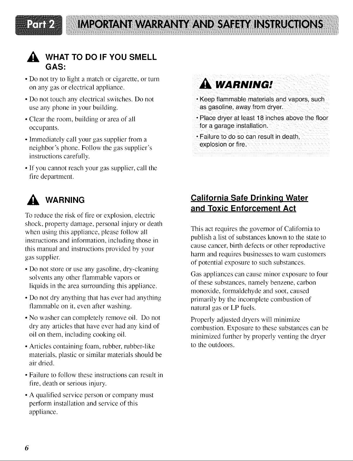
,_ WHAT TO DO IF YOU SMELL
GAS:
• Do not try to light a match or cigarette, or turn
on any gas or electrical appliance.
• Do not touch any electrical switches. Do not
use any phone in your building.
• Clear the room, building or area of all
occupants.
• Immediately call your gas supplier from a
neighbor's phone. Follow the gas supplier's
instructions carefully.
• If you cannot reach your gas supplier, call the
fire department.
_Ik WARNING
To reduce the risk of fire or explosion, electric
shock, property damage, personal injury or death
when using this appliance, please follow all
instructions and information, including those in
this manual and instructions provided by your
gas supplier.
• Do not store or use any gasoline, dry-cleaning
solvents any other flammable vapors or
liquids in the area surrounding this appliance.
• Do not dry anything that has ever had anything
flammable on it, even after washing.
• No washer can completely remove oil. Do not
dry any articles that have ever had any kind of
oil on them, including cooking oil.
• Articles containing foam, rubber, rubber-like
materials, plastic or similar materials should be
air dried.
WARNING!
• Keep flammable materials and vapors, such
as gasoline, away from dryer.
• Place dryer at least 18 inches above the floor
for a garage installation.
• Failure to do so can result in death,
explosion or fire.
California Safe Drinkinq Water
and Toxic Enforcement Act
This act requires the governor of California to
publish a list of substances known to the state to
cause cancer, birth defects or other reproductive
harm and requires businesses to warn customers
of potential exposure to such substances.
Gas appliances can cause minor exposure to four
of these substances, namely benzene, carbon
monoxide, formaldehyde and soot, caused
primarily by the incomplete combustion of
natural gas or LP fuels.
Properly adjusted dryers will minimize
combustion. Exposure to these substances can be
minimized further by properly venting the dryer
to the outdoors.
• Failure to follow these instructions can result in
fire, death or serious injury.
• A qualified service person or company must
perform installation and service of this
appliance.
6
The following instructions will help guide you through the initial steps of setting up your dryer for use.
Please note that every section of this manual provides important information regarding the preparation and
use of your dryer, and it is important that you review this entire manual before proceeding with any
installation or use. More detailed instructions concerning electrical connections, gas connections, and
exhaust requirements are provided in other parts of this manual.
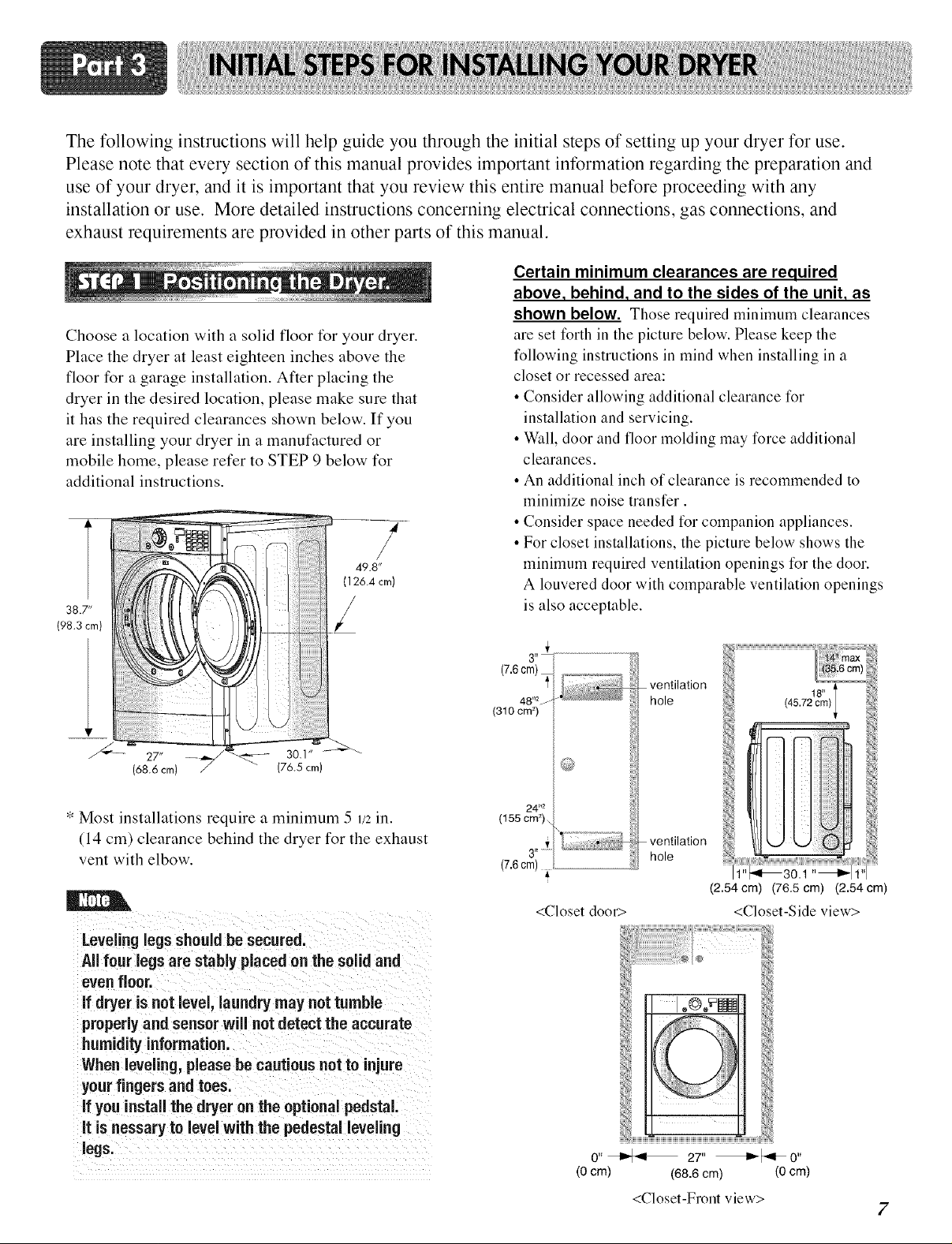
Certain minimum clearances are required
above, behind, and to the sides of the unit, as
shown below. Thoserequired minimum clearances
Choose a location with a solid floor for your dryer.
Place the dryer at least eighteen inches above the
floor for a garage installation. After placing the
dryer in the desired location, please make sure that
it has the required clearances shown below. If you
are installing your dryer in a manufactured or
mobile home, please refer to STEP 9 below for
additional instructions.
38.7"
{98.3 cm)
are set forth in the picture below. Please keep the
t_llowing instructions in mind when installing in a
closet or recessed area:
• Consider allowing additional clearance for
installation and servicing.
• Wall, door and floor molding may force additional
clearances.
• An additional inch of clearance is recommended to
minimize noise transfer.
• Consider space needed t_r companion appliances.
• For closet installations, the picture below shows the
minimnm required ventilation openings t_r the door.
A louvered door with comparable ventilation openings
is also acceptable.
(68.6 cm)
(76.5 cm)
* Most installations require a minimum 5 1/2in.
(14 cm) clearance behind the dryer for the exhaust
vent with elbow.
Leveling legs should be secured.
All four legs are stably placed on the solid and
evenfloor.
if dryer is not level, laundry may not tumble
properly and sensor will net detect the accurate
humidity information.
When leveling, please be cautious not to injure
your fingers and toes.
If you install the dryer on the optional pedstal.
it is nessary to level with the pedestal leveling
legs.
(7.6cm)
48 t_2j
(310 cm2)
24*'2
(155 cm_)..
(7.6cm)
3"
ventilation
hole
ntil at ion
v e
hole i _30.1 "_
(2.54cm) (76.5 cm) (2.54cm)
<Closet-Side view><Closet door>
0" _ 27" _1_0"
(0 cm) (68.6 cm) (0 cm)
<Closet-Front view>
7
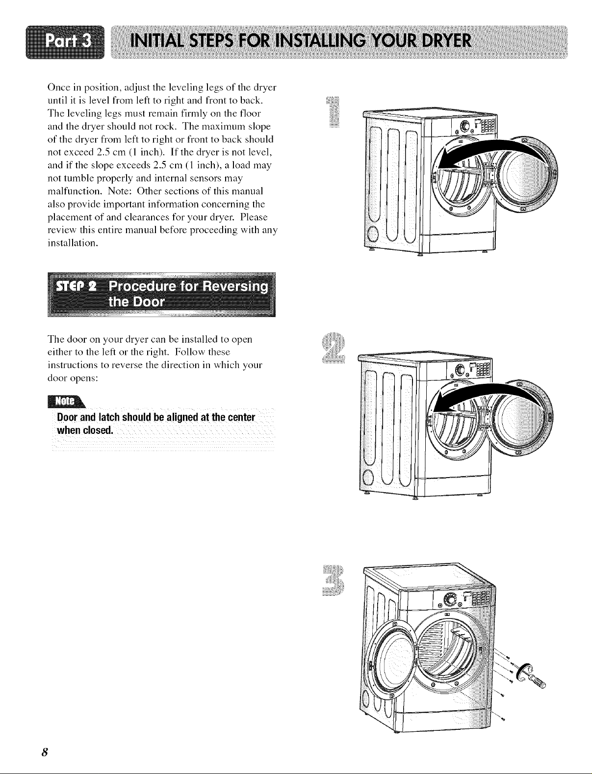
Once in position, adjust the leveling legs of the dryer
until it is level from left to right and front to back.
The leveling legs must remain firmly on the floor
and the dryer should not rock. The maximum slope
of the dryer from left to right or front to back should
not exceed 2.5 cm (1 inch). If the dryer is not level,
and if the slope exceeds 2.5 cm (1 inch), a load may
not tumble properly and internal sensors may
malfunction. Note: Other sections of this manual
also provide important information concerning the
placement of and clearances for your dryei: Please
review this entire manual before proceeding with any
installation.
The door on your dryer can be installed to open
either to the left or the right. Follow these
instructions to reverse the direction in which your
door opens:
iiiiii!i!ilii
i ! i
Door and latch should be aligned at the center
8
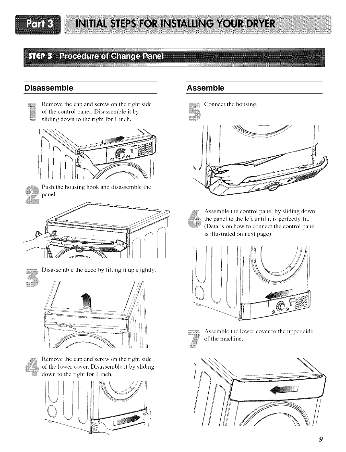
Disassemble
Assemble
Remove the cap and screw on the right side
of the control panel. Disassemble it by
sliding down to the right for 1 inch.
Push the housing hook and disassemble the
panel.
Disassemble the deco by lifting it up slightly.
Connect the housing.
Assemble the control panel by sliding down
the panel to the left until it is perfectly fit.
.... (Details on how to connect the control panel
is illustrated on next page)
of the lower cover. Disassemble it by sliding
_ emove the cap and screw on the right side
down to the right for 1 inch.
Assemble the lower cover to the upper side
of the machine.
9
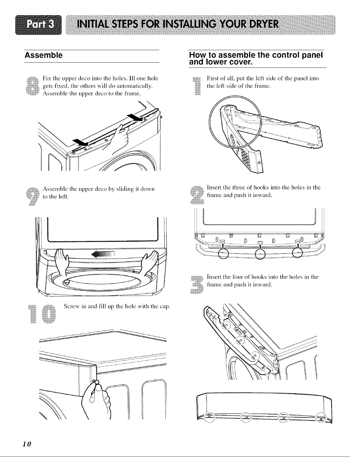
Assemble
How to assemble the control panel
and lower cover.
Fix the upper deco into the holes. Ill one hole
gets fixed, the others will do automatically.
Assemble the upper deco to the frame.
,%
Assemble the upper deco by sliding it down
to the left.
L lJ
First of all, put the left side of the panel into
the left side of the frame.
Insert the three of hooks into the holes in the
frame and push it inward.
I0
Insert the four of hooks into the holes in the
frame and push it inward.
Screw in and fill up the hole with the cap.
\
WARNING!
• Use a heavy metal vent.
• Do not use plastic or thin foil duct.
• Failure to follow these instructions can
result in death or fire.
•Clean old ducts before installing this dryer
Vent end will face to the outside home and
improper taping and unstable installation of vent
will cause undesirable drying performance,
In addition to the following warnings, please refer
to manual section on Exhaust Requirements and
Maintenance. IMPORTANT: To reduce the risk of
fire, combustion, and gas accumulation, the dryer
must be vented to the outdoors. Please follow the
instructions (and all others in this manual) very
carefully.
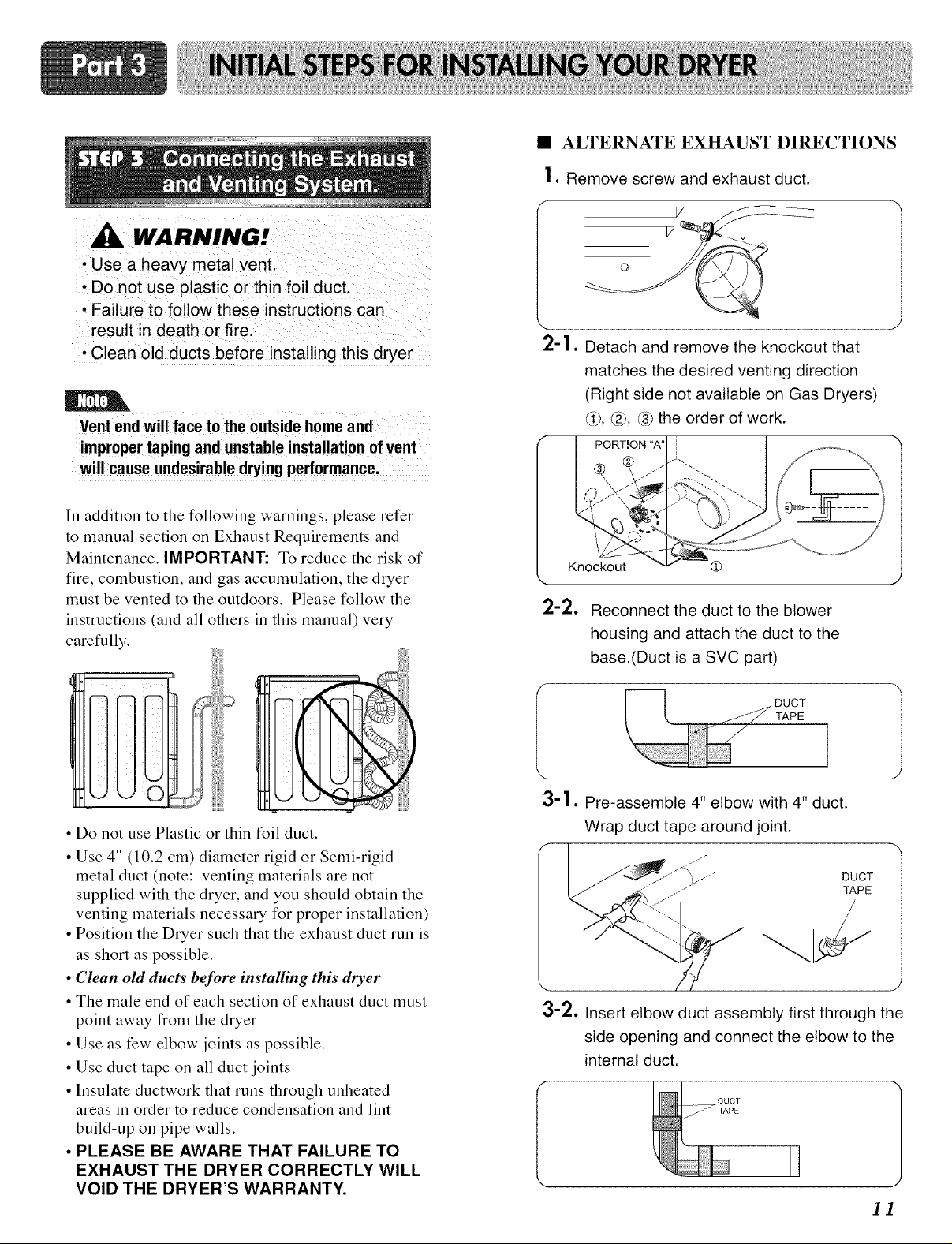
• ALTERNATE EXHAUST DIRECTIONS
2-2.
Knockout
Reconnect the duct to the blower
housing and attach the duct to the
base.(Duct is a SVC part)
@
• Do not use Plastic or thin foil duct.
• Use 4" (10.2 cm) diameter rigid or Semi-rigid
metal duct (note: venting materials are not
supplied with the dryer, and you should obtain the
venting materials necessary for proper installation)
• Position the Dryer such that the exhaust duct run is
as short as possible.
• Clean old duets beJbre installing this dryer
• The male end of each section of exhaust duct must
point away from the dryer
• Use as few elbow joints as possible.
• Use duct tape on all duct joints
• Insulate ductwork that runs through unheated
areas in order to reduce condensation and lint
build-up on pipe walls.
• PLEASE BE AWARE THAT FAILURE TO
EXHAUST THE DRYER CORRECTLY WILL
VOID THE DRYER'S WARRANTY.
TAPE
3-1. Pre-assemble 4" elbow with 4" duct.
Wrap duct tape around joint.
DUCT
TAPE
3-2. Insert elbow duct assembly first through the
side opening and connect the elbow to the
internal duct.
11
 Loading...