

Page 1
www.LGEservice.com
DISCOVERY DRYER
TRAINING MANUAL
CAUTION!
READ THIS MANUAL CAREFULLY
BEFORE DIAGNOSING OR SERVICING THIS PRODUCT.
Page 2

Customer Service (and Part Sales) (800) 243-0000
Technical Support (and Part Sales) (800) 847-7597
USA Website us.lgservice.com
Customer Service Website us.lgservice.com
B2B Service Website biz.lgservice.com
LG CS Academy lgcsacademy.com
Published April 2006 by LG Technical Support and Training
Page 3

DRYER
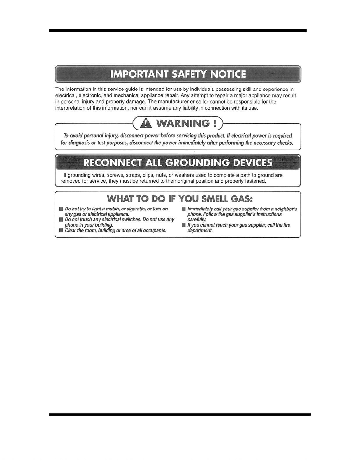
IMPORTANT SAFETY NOTICE
The information in this training manual is intended for use by persons possessing an adequate background
in electrical equipment, electronic devices, and mechanical systems. In any attempt to repair a major
appliance, personal injury and property damage can result. The manufacturer or seller maintains no liability
for the interpretation of this information, nor can it assume any liability in conjunction with its use. When
servicing this product, under no circumstances should the original design be modified or altered without
permission from LG Electronics. Unauthorized modifications will not only void the warranty, but may lead to
property damage or user injury. If wires, screws, clips, straps, nuts, or washers used to complete a ground
path are removed for service, they must be returned to their original positions and properly fastened.
CAUTION
To avoid personal injury, disconnect the power before servicing this product. If electrical power is required
for diagnosis or test purposes, disconnect the power immediately after performing the necessary checks.
Also be aware that many household appliances present a weight hazard. At least two people should be
involved in the installation or servicing of such devices. Failure to consider the weight of an appliance could
result in physical injury.
ESD NOTICE
Some of the electronic components in appliances are electrostatic discharge (ESD) sensitive. ESD can
weaken or damage the electronics in these appliances in a manner that renders them inoperative or reduces
the time until their next failure. Connect an ESD wrist strap to a ground connection point or unpainted metal
in the appliance. Alternatively, you can touch your finger repeatedly to a ground connection point or
unpainted metal in the appliance. Before removing a replacement part from its package, touch the anti-static
bag to a ground connection point or unpainted metal in the appliance. Handle the electronic control
assembly by its edges only. When repackaging a failed electronic control assembly in an anti-static bag,
observe these same precautions.
REGULATORY INFORMATION
This equipment has been tested and found to comply with the limits for a Class B digital device, pursuant to
Part 15 if the FCC Rules. These limits are designed to provide reasonable protection against harmful
interference when the equipment is operated in a residential installation. This equipment generates, uses,
and can radiate radio frequency energy, and, if not installed and used in accordance with the instruction
manual, may cause harmful interference to radio communications. However, there is no guarantee that
interference will not occur in a particular installation. If this equipment does cause harmful interference to
radio or television reception, which can be determined by turning the equipment off and on, the user is
encouraged to try to correct the interference by one or more of the following measures: Reorient or relocate
the receiving antenna; Increase the separation between the equipment and the receiver; Connect the
equipment to an outlet on a different circuit than that to which the receiver is connected; or consult the
dealer or an experienced radio/TV technician for help.
COMPLIANCE
The responsible party for this device’s compliance is LG Electronics Alabama, Inc.; 201 James Record Road,
Huntsville, AL, 35824.
DLE8377xM/DLG8388xM
DLE7177WM/DLG7188WM Page 3 of 60 TRAINING MANUAL
Page 4

DRYER
Contents
Regulatory Notices 3
Contents 4
Introduction 6
Sensor Dry 7
Manual Dry 7
Gas Safety Page 8
Specifications 9
Accessories 10
Installation (of accessories) 10
Rack 10
Stacking Kit 11
Pedestal 13
Modem and Monitor 15
Electric Dryer 16
Pigtail 16
4-wire Connection 16
3-wire Connection 17
Gas Dryer 19
Piping 19
Dryer Cycle Chart 20
Component Test Procedures 21
Motor Diagram and Schematic 22
Safety Switches 25
Control and PCB Layout 26
Wiring Diagram 28
Diagnostic Test 29
Test 1 – 120 V AC Electrical Supply 30
Test 2 – Thermistor Test (Power Off) 33
Test 3 – Motor Test 34
Test 4 – Moisture Sensor Test 35
Test 5 – Door Switch Test 36
Test 6 – Heater Switch Test (Electric Dryer) 37
Test 7 – Gas Valve Test (Gas Dryer) 38
Test 8 – Semiconductor Test 39
Gas Conversion (Natural to Propane) 40
Safety Warning 40
Orifice 41
Gas Valve Operation 42
Flow Chart 42
Ignition Sequence 42
continued on next page Æ
DLE8377xM/DLG8388xM
DLE7177WM/DLE7188WM Page 4 of 60 TRAINING MANUAL
Page 5

DRYER
Contents, continued
Disassembly/Repair 43
Top Cover 43
Control Panel 44
Front Cover and Door 45
Door Reversal 45
Tub Front 46
Drum Assembly and Belt 46
Lamp 47
Filter Assembly and Moisture Sensor 49
Back Cover 49
Air Duct 50
Rollers 51
Blower and Housing 52
Exploded Views 53
Top Cover and Control Panel 53
Cabinet and Door 54
Drum and Motor (Electric Dryer) 55
Drum and Motor (Gas Dryer) 56
Parts List 57
Vent Replacement (Rear to side exhaust) 48
DLE8377xM/DLG8388xM
DLE7177WM/DLE7188WM Page 5 of 60 TRAINING MANUAL
Page 6
DRYER
INTRODUCTION
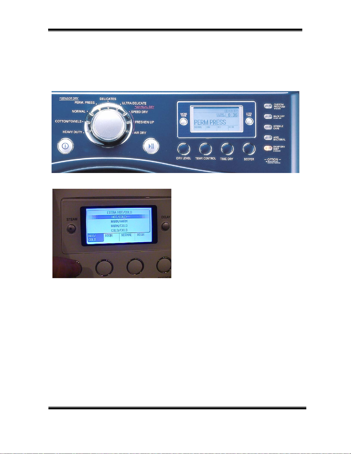
The DISCOVERY dryer is very similar to other LG dryers with the exception of
the LCD display on the control panel. The LCD display shows all the information
formerly indicated by LEDs but also allows for scrolling instruction.
When a cycle is selected, the
options are preset. They can be
overridden by changing them using
the option buttons.
Pressing the buttons cycles through
the available options. If an option is
not available for a particular cycle, it
is grayed out or not available for
selection. For example, the EXTRA
HOT wash is not available for the
DELICATE cycle.
The interior components remain the same: motor, belt, drum, and heat source
(gas or electric). The gas model can be refitted with an orifice to allow the use of
propane instead of natural gas. All such conversions and adjustments should be
performed by a licensed and certified gasfitter.
The DISCOVERY model also has an additional sensor in the exhaust stream to
detect the moisture level more accurately for better drying results.
DLE8377xM/DLG8388xM
DLE7177WM/DLE7188WM Page 6 of 60 TRAINING MANUAL
Page 7
DRYER
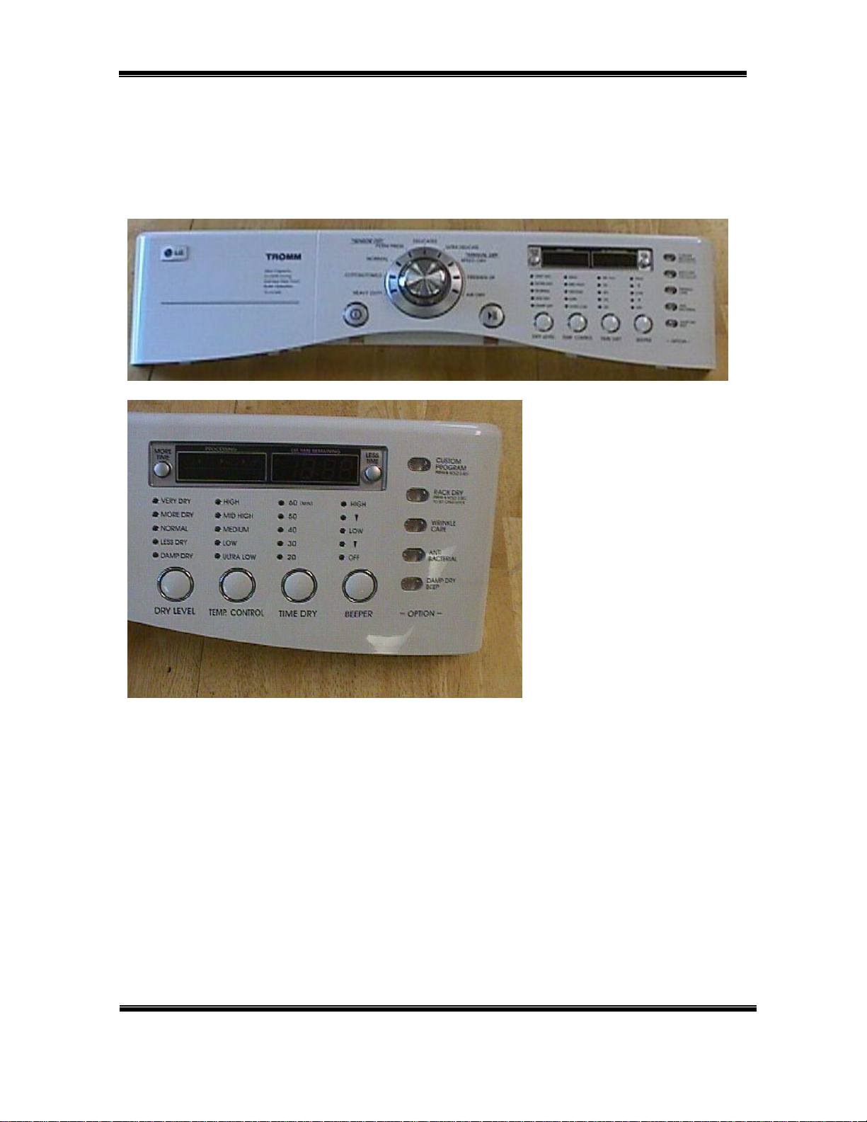
Models DLE7177WM and DLG7188WM use the LED indicator panel instead of
the newer LCD. The only difference is the type of display. The dryers function
identically. The main and display PCB (Printed Circuit Board) will carry a different
part number depending upon the type of display. Always order parts by model
number and serial number to ensure receiving the correct parts.
The drying cycle is shown
in the left window and the
time remaining is show in
the right. Feature
selections like DRY
LEVEL and BEEPER
volume are indicated by
LEDs on the panel.
The DISCOVERY line of dryers feature enhanced sensor drying. In addition to
the drying sensor in the tub near the filter, there is an additional sensor in the
exhaust stream to ensure the correct level of dryness is determined, from damp
dry to very dry. The dryer can also be set manually to dry at a particular heat
level and for a specified time.
DLE8377xM/DLG8388xM
DLE7177WM/DLE7188WM Page 7 of 60 TRAINING MANUAL
Page 8
DRYER
SAFETY
Check the local laws and regulations concerning the installation and connection
of gas. In most localities, it is illegal to connect gas piping, re-jet or adjust burners,
or repair gas-fired equipment unless you are licensed and certified so to do. It is
the servicer’s responsibility to comply with all such regulation.
DLE8377xM/DLG8388xM
DLE7177WM/DLE7188WM Page 8 of 60 TRAINING MANUAL
Page 9

DRYER
SPECIFICATIONS
DLE8377xM/DLG8388xM
DLE7177WM/DLE7188WM Page 9 of 60 TRAINING MANUAL
Page 10

DRYER
ACCESSORIES
DRYING RACK STACKING KIT PEDESTAL
The DRYING RACK is used to dry items that should not be tumbled, like
sweaters, tennis shoes, etc. It should be removed and stored when not in use.
The rack is included with the dryer. (See installation procedure, page xx.)
The STACKING KIT is used to stack a dryer on top of a matching washer.
(NEVER put a washer on top of a dryer!) The stacking kit should not be used in
situation where there is the possibility of excessive vibration and movement of
the washer, such as in a mobile home or an upper floor of a frame structure. The
stacking kit is available as an optional purchase. (See installation procedure,
page 11.)
The PEDESTAL can be used under either the washer or the dryer. It is possible
to stack a washer and dryer on a pedestal, but the dryer controls may be difficult
to reach and the possibility of vibration and movement is greater. The pedestal is
available as an optional purchase. (See installation procedure, page 13.)
Pedestals are available in heights of 7¼” and 13”.
INSTALLATION (RACK)
It’s simple!
Open the dryer door.
Put the rack in place.
Select RACK DRY (2
Press START.
Be sure the front of the rack is properly
situated in the notches on either side
of the filter. The back should rest on
the drum and allow the drum to rotate.
nd
button on right)
DLE8377xM/DLG8388xM
DLE7177WM/DLE7188WM Page 10 of 60 TRAINING MANUAL
Page 11

DRYER
INSTALLATION (Stacking Kit)
WARNING! Do not attempt this alone! At least two people are required to lift the
dryer and place it properly on top of the washer. Failure to observe this warning
could result in serious physical injury and damage to the appliances.
1. Place the washer on a solid,
even floor. If you plan to use a
pedestal, install it now before
going any further.
2. Peel the protective paper from
the adhesive tape on the side
bracket.
3. Fit the side bracket firmly to the
top plate using the adhesive
tape, as shown in the drawing.
4. Secure the bracket to the top
plate using a screw, as shown.
Repeat steps 2, 3, and 4 for the
other side.
5. Level the dryer on a firm solid
floor and lock down the
adjusters before placing it on top
of the washer. (See page xx.)
Lift the dryer on top of the
washer it toward the front of the
washer, as shown.
Slide the dryer all the way back
to the stop on the rail.
DLE8377xM/DLG8388xM
DLE7177WM/DLE7188WM Page 11 of 60 TRAINING MANUAL
Page 12

DRYER
INSTALLATION (Stacking Kit) continued
6. Install the front rail of the
stacking kit. Push the front rail
back against the stops on the
side brackets.
7. Insert a screw to attach the front
rail to the side bracket.
Repeat step 7 for the other side.
DLE8377xM/DLG8388xM
DLE7177WM/DLE7188WM Page 12 of 60 TRAINING MANUAL
Page 13
DRYER
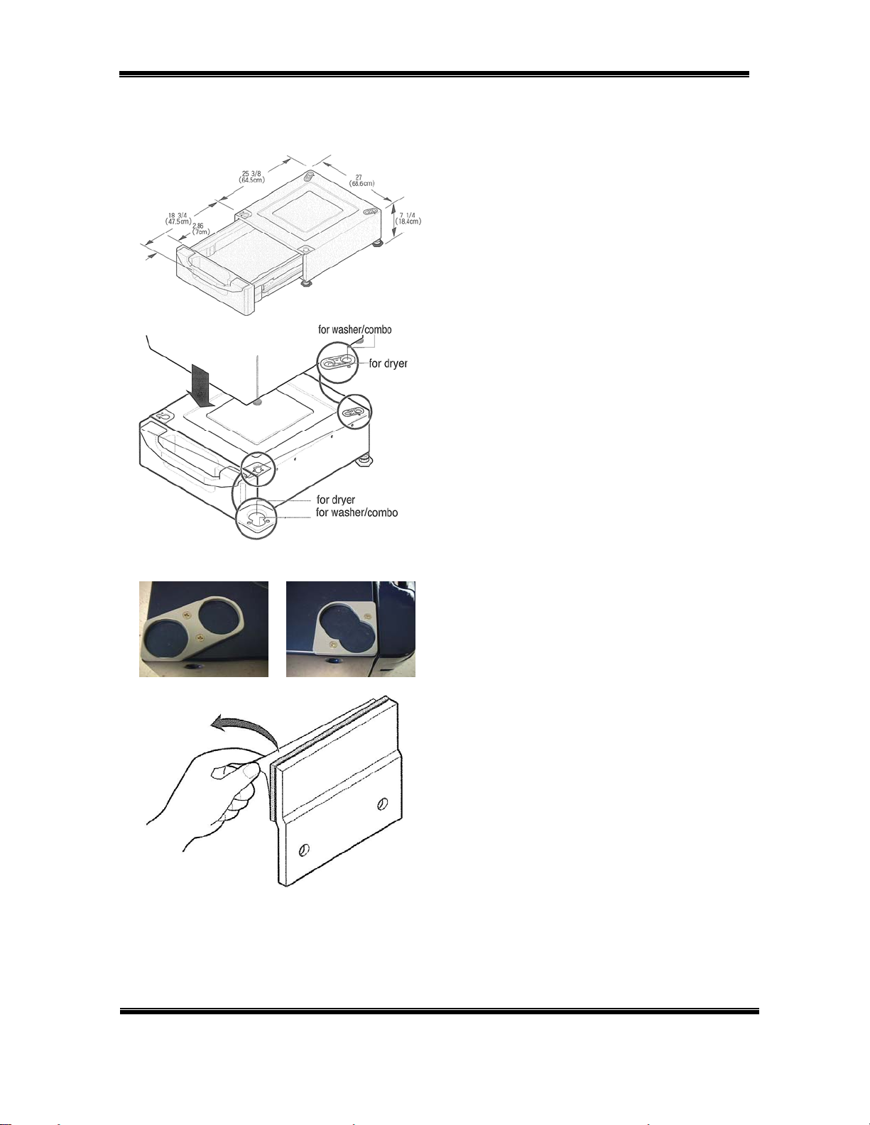
INSTALLATION (Pedestal)
1. Remove the pedestal,
installation hardware, and
instructions from the shipping
container.
2. Level the pedestal on a solid,
flat, level floor. Lock down the
rear adjusters, but leave the
front ones free for now.
Set the dryer on the pedestal
and level it. Level it and lock
down all four adjusters on the
dryer.
Note which holes are for the
REAR FRONT
washer and which are for the
dryer. If you are stacking the
appliances, the washer should
be on the bottom.
For 27” Pedestals
(Washer, Dryer, and Combo)
3. Remove the protective paper
from the adhesive surface of the
bracket.
Be particularly careful, because when
this adhesive makes contact, there is
no adjustment possible.
NOTE: Some kits include two sets of
brackets (curved for the dryer and flat
(shown) for the washer.) Use the
correct bracket for your application.
(See next page.)
DLE8377xM/DLG8388xM
DLE7177WM/DLE7188WM Page 13 of 60 TRAINING MANUAL
Page 14

DRYER
INSTALLATION (Pedestal) continued
4. Holding the adhesive part of the
bracket away from the dryer,
insert the screws and get them
started.
Press the bracket onto the dryer
and tighten the screws.
5. Press the brackets onto the
sides of the dryer and rub the
brackets from side to side to
ensure the total adhesive area is
attached completely.
6. Tighten all the screws securely.
7. Lower each leg of the dryer one fourth turn with the adjusting
wrench to put a little pressure
between the dryer and pedestal
to prevent any motion and
rattling.
8. Push the dryer into place.
9. Check the level and adjust the
front legs of the pedestal as
necessary. Then lock down the
adjusters.
The pedestal kit includes the mounting
plates (with adhesive covered by
paper) and the screws to attach the
plates. Remember, some pedestal kits
come with two sets of brackets. The flat
tops are for washers; the curved tops
(shown) are for dryers. Use the correct
brackets for your application.
DLE8377xM/DLG8388xM
DLE7177WM/DLE7188WM Page 14 of 60 TRAINING MANUAL
Page 15
DRYER
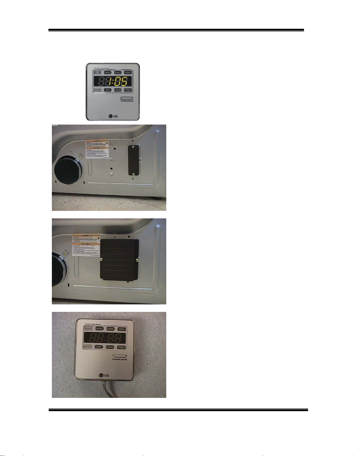
INSTALLATION (Modem and Monitor)
The monitor plugs in to any 110 Volt
outlet in the home. It receives its data
signal via the power lines.
1. Be sure the dryer is unplugged.
Remove the modem cover.
Save the cover for future use; in
the event you must remove the
modem, you can replace the
cover.
REMOTE MONITOR
2. Attach the modem to the socket
with the screws provided.
3. Plug the monitor’s power cord
in an outlet where you can
observe it easily. Use the stand
or the wall mount bracket.
4. Press and hold the button until
the display shows SET.
DLE8377xM/DLG8388xM
DLE7177WM/DLE7188WM Page 15 of 60 TRAINING MANUAL
Page 16

DRYER
ELECTRICAL CONNECTION (Electric Dryer Only)
PIGTAIL INSTALLATION
Install the appropriate power cord for the outlet available. Grounding through the
neutral conductor is prohibited in new branch-circuits, mobile homes, recreational
vehicles, and where prohibited by local code.
4-wire Connection
The 4-wire receptacle looks like this.
Power cord with spade terminals.
Power cord with ring terminals.
Install a strain relief on the power cord.
Then connect the terminals to the
terminal block, matching the wire
colors.
A. Ground screw on chassis
B. Green wire from power cord
C. Strain relief
D. Neutral screw on terminal block
E. Terminal block
F. Neutral wire from power cord
DLE8377xM/DLG8388xM
DLE7177WM/DLE7188WM Page 16 of 60 TRAINING MANUAL
Page 17

DRYER
ELECTRICAL CONNECTION (Electric Dryer Only) continued
3-wire Connection
The 3-wire receptacle looks like this.
Power cord with spade terminals.
Power cord with ring terminals.
Install a strain relief on the power cord.
Then connect the terminals to the
terminal block, matching the wire
colors. Add a wire to connect the
chassis ground to neutral.
A. Ground screw on chassis
B. Green wire from power cord
C. Strain relief
D. Neutral screw on terminal block
E. Ground-to-neutral connection
F. Neutral wire from power cord
DLE8377xM/DLG8388xM
DLE7177WM/DLE7188WM Page 17 of 60 TRAINING MANUAL
Page 18

DRYER
ELECTRICAL CONNECTION (Electric Dryer Only) continued
Be sure to tighten all screws firmly, but
do not strip them or distort the contact
area.
Be sure to install a strain relief on the
power cord.
Replace the terminal block cover by
inserting the tabs into the slots and
letting them slide down to engage.
Fold it over to the back of the dryer so
it covers the access to the terminal
block. Be sure no wires are exposed or
could touch any metal surface.
Secure the cover with a screw.
DLE8377xM/DLG8388xM
DLE7177WM/DLE7188WM Page 18 of 60 TRAINING MANUAL
Page 19

DRYER
GAS CONNECTION (Gas Dryer Only)
CAUTION! (This warning applies to both natural gas and propane.)
Gas is both flammable and explosive. Use caution when working with gas.
In most locations, installing and connecting gas is restricted to properly trained
and licensed persons.
Always inspect joints and connections for a leak with a soapy solution. If you see
bubbles, turn the gas off and open a window. If you smell gas, turn off the main
valve and open a window.
The gas dryer requires a 110 Volt, single-outlet, dedicated circuit. The cord is
installed at the factory and no user-intervention is required.
DLE8377xM/DLG8388xM
DLE7177WM/DLE7188WM Page 19 of 60 TRAINING MANUAL
Page 20

DRYER
DRYER CYCLE CHART
* SENSOR DRY The dryness level is set by the customer.
** MANUAL DRY The temperature is set by the customer.
The default settings can be overridden by the customer.
DLE8377xM/DLG8388xM
DLE7177WM/DLE7188WM Page 20 of 60 TRAINING MANUAL
Page 21

DRYER
COMPONENT TESTING PROCEDURES
Testing the various components of the dryer is relatively simple. Most can be
checked without major disassembly.
DLE8377xM/DLG8388xM
DLE7177WM/DLE7188WM Page 21 of 60 TRAINING MANUAL
Page 22

DRYER
COMPONENT TESTING PROCEDURES continued
DLE8377xM/DLG8388xM
DLE7177WM/DLE7188WM Page 22 of 60 TRAINING MANUAL
Page 23

DRYER
COMPONENT TESTING PROCEDURES continued
DLE8377xM/DLG8388xM
DLE7177WM/DLE7188WM Page 23 of 60 TRAINING MANUAL
Page 24

DRYER
MOTOR DIAGRAM and SCHEMATIC
To check the motor, turn the power off and allow the capacitor to discharge.
The centrifugal switch serves as a safety device to turn off the fuel (gas or
electricity) to the heater if the motor fails to rotate.
DLE8377xM/DLG8388xM
DLE7177WM/DLE7188WM Page 24 of 60 TRAINING MANUAL
Page 25

DRYER
SAFETY SWITCHES
The centrifugal switch slides back and forth on the motor’s shaft to operate the
contacts as shown in the previous diagram. This switch provides safety in the
event the motor fails. When the motor is running, centrifugal force causes the
weight (black wing in photo) to slide back toward the motor windings. This motion
allows electricity to operate the heater (electric element or gas valve). If the
motor stops, the weight slides forward and turns the power off.
RUN POSITION STOP POSITION
There is an additional safety in the form of a belt switch that shuts off power to
the electric motor if the belt breaks. Belt tension holds the switch closed. If the
belt breaks, the switch opens and power to the motor is cut. When the motor
stops, the centrifugal switch functions as a safety device to turn off the fuel (gas
or electricity).
The centrifugal switch includes a multipin connector (shown).
The belt switch is simple. If the belt
breaks, the spring pulls the lever down
and it presses the switch.
DLE8377xM/DLG8388xM
DLE7177WM/DLE7188WM Page 25 of 60 TRAINING MANUAL
Page 26

DRYER
DISPLAY PWB
The display board is actually two boards connected by a ribbon cable. One board
holds the selector knob and cycle indicator LEDs. The other holds the LCD
display and adjustment buttons to override the pre-set cycle selections.
The DLE7177WM board is shown below. Other models vary slightly.
The gas and electric models have a different display board.
DLE8377xM/DLG8388xM
DLE7177WM/DLE7188WM Page 26 of 60 TRAINING MANUAL
Page 27

DRYER
MAIN PWB
The main board includes the relays that operate electric heaters and gas valves.
The DLE7177WM board is shown below. Other models vary slightly.
The gas and electric models have a different main board.
DLE8377xM/DLG8388xM
DLE7177WM/DLE7188WM Page 27 of 60 TRAINING MANUAL
Page 28

DRYER
Electric Dryer Wiring Diagram
Gas Dryer Wiring Diagram
DLE8377xM/DLG8388xM
DLE7177WM/DLE7188WM Page 28 of 60 TRAINING MANUAL
Page 29

DRYER
DIAGNOSTIC TEST MODE
The diagnostic test mode is for service testing only. Do not activate the heater
manually with the door open or it will trip the thermostat attached to the heater.
1. Dryer must be in standby mode. (Plugged in, turned off)
2. Press and hold MORE TIME and LESS TIME, then press power.
3. Press START/PAUSE to advance to the next test.
4. Unplug the dryer for one minute after using the diagnostic mode.
DLE8377xM/DLG8388xM
DLE7177WM/DLE7188WM Page 29 of 60 TRAINING MANUAL
Page 30

DRYER
DIAGNOSTIC TEST PROCEDURES
The following pages will assist in troubleshooting and diagnosing issues with the
dryer. Each test will list the appropriate precautionary measures along with
symptoms and the conditions under which the testing should be performed.
TEST 1 – 120 V AC ELECTRICAL SUPPLY
WARNING! Use insulated gloves to avoid electrical shock.
SYMPTOM! No power, display off.
CONDITION! Power on to dryer, controller connected.
continued on next page
DLE8377xM/DLG8388xM
DLE7177WM/DLE7188WM Page 30 of 60 TRAINING MANUAL
Page 31

DRYER
WARNING! Use insulated gloves to avoid electrical shock.
SYMPTOM! Check the TAB RELAY connections.
CONDITION! Power on to dryer, controller connected.
POWER CONNECTION
CONNECTION STATUS (Electric)
CONNECTION STATUS (Electric)
DLE8377xM/DLG8388xM
DLE7177WM/DLE7188WM Page 31 of 60 TRAINING MANUAL
Page 32

DRYER
If the power connection is reversed, the dryer will not operate and components
can be damaged.
CONNECTION STATUS REVERSED (Incorrect) (Electric)
CONNECTION STATUS REVERSED (Incorrect) (Gas)
DLE8377xM/DLG8388xM
DLE7177WM/DLE7188WM Page 32 of 60 TRAINING MANUAL
Page 33

DRYER
TEST 2 – Thermistor Test (Power Off)
WARNING! Use insulated gloves to avoid electrical shock.
SYMPTOM! tE1 and tE2 error codes occur during the test.
Heater does not turn off.
Significant difference between actual and sensed
temperature.
CONDITION! Power off.
Table – Thermistor resistance/temperature
DLE8377xM/DLG8388xM
DLE7177WM/DLE7188WM Page 33 of 60 TRAINING MANUAL
Page 34

DRYER
TEST 3 – Motor Test
WARNING! Discharge (see below) before measuring resistance.
SYMPTOM! Motor, fan, and heater do not function.
CONDITION! Turn power off, unplug dryer, and discharge by shorting line
and neutral to ground at the end of the power cord.
DLE8377xM/DLG8388xM
DLE7177WM/DLE7188WM Page 34 of 60 TRAINING MANUAL
Page 35

DRYER
TEST 4 – Moisture Sensor Test
WARNING! Discharge (see below) before measuring resistance.
SYMPTOM! Dryness of clothing does not match set dry level.
CONDITION! Turn power off, unplug dryer, and discharge by shorting line
and neutral to ground at the end of the power cord.
Measure resistance.
Table – IMC Ratio and Display Value (IMC = Initial Moisture Content)
DLE8377xM/DLG8388xM
DLE7177WM/DLE7188WM Page 35 of 60 TRAINING MANUAL
Page 36

DRYER
TEST 5 – Door Switch Test
WARNING! Discharge before measuring resistance.
SYMPTOM! Door opening not sensed (dryer runs with door open).
CONDITION! Turn dryer off, unplug, discharge, and measure resistance.
DLE8377xM/DLG8388xM
DLE7177WM/DLE7188WM Page 36 of 60 TRAINING MANUAL
Page 37

DRYER
TEST 6 – Heater Switch (Electric Dryer Only)
WARNING! Discharge before measuring resistance.
SYMPTOM! Heater does not operate.
CONDITION! Turn power off, unplug, discharge, and measure resistance.
DLE8377xM/DLG8388xM
DLE7177WM/DLE7188WM Page 37 of 60 TRAINING MANUAL
Page 38

DRYER
TEST 7 – Gas Valve Test (Gas Dryer Only)
WARNING! Use insulated gloves to avoid electrical shock.
SYMPTOM! Heater does not operate.
CONDITION! Power on.
DLE8377xM/DLG8388xM
DLE7177WM/DLE7188WM Page 38 of 60 TRAINING MANUAL
Page 39

DRYER
TEST 8 – Semiconductor (Sensor) Test
WARNING! Discharge before measuring resistance.
SYMPTOM! Resistance is not 300Ω ± 20Ω
CONDITION! Turn power off, unplug, discharge, and measure resistance.
DLE8377xM/DLG8388xM
DLE7177WM/DLE7188WM Page 39 of 60 TRAINING MANUAL
Page 40

DRYER
GAS CONVERSION (Natural to Propane)
WARNING! Improper installation and/or adjustment of orifices and gas valves
can result in fire, explosion, and suffocation. Installation and
adjustment should be performed ONLY by a trained, licensed, and
certified gasfitter.
NOTICE! The dryer is shipped from the factory equipped for natural gas.
1. Close the adjustment screw.
Notice there is a nut on the adjustment
screw. This nut is secured to the thread
with a sealing compound. The nut is
pre-positioned to the place the valve
would be properly adjusted for LP. It’s
purpose is to provide a shoulder for
positioning the adjustment screw if the
dryer is converted from natural gas to
propane.
NOTE: The conversion should be
performed by a licensed and certified
gasfitter.
DLE8377xM/DLG8388xM
DLE7177WM/DLE7188WM Page 40 of 60 TRAINING MANUAL
Page 41

DRYER
GAS CONVERSION (Natural to Propane) continued
2. Replace the orifice. (See photo, previous page.]
You’ll have to remove the top plate and front cover to change the orifice.
Installing the correct orifice is critical! This should be performed ONLY by
trained, licensed, and certified service personnel.
3. The conversion kit includes a propane orifice, complete instructions for
making the conversion, and a label indicating the conversion kit has
been installed. All conversion work, including testing and adjusting, must
be completed by a trained, licensed, and certified gasfitter.
DLE8377xM/DLG8388xM
DLE7177WM/DLE7188WM Page 41 of 60 TRAINING MANUAL
Page 42

DRYER
GAS VALVE OPERATION
The gas valve is a two-stage valve. When the ignition sequence begins, the
igniter is turned on and valve one opens. When the igniter reaches 370° F
(188° C), the igniter is turned off and valve two is opened. If the flame detector
does not detect ignition, valve two is closed and the process is restarted. If
ignition occurs as planned, the drying cycle will operate.
GAS IGNITION SEQUENCE GAS VALVE CONSTRUCTION
IGNITION FLOW CHART
DLE8377xM/DLG8388xM
DLE7177WM/DLE7188WM Page 42 of 60 TRAINING MANUAL
Page 43

DRYER
DISASSEMBLY and REPAIR INSTRUCTIONS
TOP PLATE
1. Remove three screws along the
back of the top (cover) plate.
2. Slide the top plate backward.
3. Lift the top plate off and set it
aside.
DLE8377xM/DLG8388xM
DLE7177WM/DLE7188WM Page 43 of 60 TRAINING MANUAL
Page 44

DRYER
CONTROL PANEL
1. Remove two screws, one on
each corner of the control panel.
2. Disconnect all connectors.
NOTE: The connectors are all
different to prevent
misassembly.
3. Pull the control panel upward,
then forward. Be sure to
disengage all the plastic tabs
along the top.
4. Lay the control panel on its face
on a soft, protective cloth.
5. Remove nine screws on the
display PWB.
6. Remove four screws on the
main PWB.
7. Disassemble the control panel.
DLE8377xM/DLG8388xM
DLE7177WM/DLE7188WM Page 44 of 60 TRAINING MANUAL
Page 45

DRYER
FRONT CABINET
1. Remove the top plate.
2. Remove the control panel.
3. Remove the door, if necessary
for the repair.
4. Remove two screws in the
bottom of the door opening.
5. Remove four screws from the
top of the front cabinet.
6. Tilt the front away from the dryer
and disconnect the door switch
wire harness.
DOOR REVERSAL
1. Remove two screws that hold
the door. Remove the door and
set it aside on a soft, protective
cloth. Save the hinge shim.
2. Remove two screws near the
latch.
3. Remove two screws and the
latch piece.
4. Rotate everything 180° and
reinstall so the door opens from
the other side.
DLE8377xM/DLG8388xM
DLE7177WM/DLE7188WM Page 45 of 60 TRAINING MANUAL
Page 46

DRYER
TUB FRONT
1. Remove the top plate.
2. Remove the front cabinet.
3. Disconnect the door lamp (top)
and electrode sensor (bottom).
4. Remove the four screws holding
the front assembly.
5. Lift the tub front up and away.
DRUM, BELT, and PULLEY
1. Remove the drum front.
2. Reach in and remove the belt
from the motor and pulley.
3. Lift the drum out through the
front of the dryer. The belt
will still be around the drum.
4. To replace the drum, put the belt
around it and set into the dryer
to rest on the two rubber wheels
on the tub back. Let the belt
hang.
6. Replace the tub front, holding
the drum up so it can set on the
two rubber wheels on the tub
front.
7. Make sure the belt is around the
circumference of the drum near
the point where it usually rides.
8. Reach in through the front or the
side and loop the belt around
the motor shaft and the pulley.
Rotate the drum by hand a
couple of turns to seat it.
DLE8377xM/DLG8388xM
DLE7177WM/DLE7188WM Page 46 of 60 TRAINING MANUAL
Page 47

DRYER
DRUM LAMP
The drum light can usually be changed without a major disassembly, unless the
bulb is frozen in the socket. If the bulb can’t be changed using this procedure,
you’ll have to remove the front cover and the lampholder to get to the socket.
1. Open the door.
2. Hold the lamp shield in place
and remove the screw.
3. Slide the shield toward the
screw and remove it.
4. Unscrew the bulb and replace it
with a 15-watt, 120 V,
candelabra-base bulb.
5. Replace the shield and screw.
Notice the bulb holder has feet that
hold it in place and tabs to keep it
positioned properly.
The socket can be removed and
replaced by squeezing the tabs and
pulling the bulb and socket into the
housing. Press it back into place after
changing the bulb.
DLE8377xM/DLG8388xM
DLE7177WM/DLE7188WM Page 47 of 60 TRAINING MANUAL
Page 48

DRYER
VENT REPLACEMENT
1. Use the VENT KIT to change
the exhaust direction.
(Part # 383EEL9001B)
On the back of the dryer,
remove the screw securing the
exhaust duct.
2. (A) Remove the knockout on the
left, right*, or bottom, as
necessary.
* Right vent option not available
on gas dryers due to internal
piping interference.
(B) Insert the replacement pipe.
(C) Attach the pipe with a screw.
3. Pre-assemble the elbow and a
replacement duct and secure
the joint with duct tape.
4. Insert the pre-assembled elbow
into the dryer through the vent
hole and connect it to the
internal pipe.
5. Tear off some pieces of duct
tape and secure that joint as
well.
6. Connect the pipe to the exhaust
duct.
DLE8377xM/DLG8388xM
DLE7177WM/DLE7188WM Page 48 of 60 TRAINING MANUAL
Page 49

DRYER
FILTER ASSEMBLY and MOISTURE SENSOR
1. Remove the lint filter.
2. Remove three screws holding
the cover grid.
3. Remove the cover grid.
4. Disconnect the electrode
sensors.
BACK COVER
1. Remove the top plate.
2. Remove the front cover.
3. Remove the tub front.
4. Remove the drum.
5. Remove 7 screws.
6. Remove the back cover.
DLE8377xM/DLG8388xM
DLE7177WM/DLE7188WM Page 49 of 60 TRAINING MANUAL
Page 50

DRYER
AIR DUCT
1. Remove the top plate.
2. Remove the front cover.
3. Remove the filter.
4. Remove 2 screws at the top of
the air duct.
5. Remove the air duct.
DLE8377xM/DLG8388xM
DLE7177WM/DLE7188WM Page 50 of 60 TRAINING MANUAL
Page 51

DRYER
ROLLERS
1. Remove the top plate.
2. Remove the front cover.
3. Remove the tub front.
4. Remove the drum (if replacing
the back rollers.)
5. Use an open-end wrench to
remove and replace the shaft
and roller.
NOTE:
If the shaft is OK and you are replacing
only the roller, you can squeeze the
triangular retainer to remove and
replace the roller without removing the
shaft from the machine.
Be sure to install the small bushings.
These must be between the roller and
the retainer on both sides of the roller.
See photo.
DLE8377xM/DLG8388xM
DLE7177WM/DLE7188WM Page 51 of 60 TRAINING MANUAL
Page 52

DRYER
BLOWER HOUSING
1. Remove the top plate.
2. Remove the front cover.
3. Remove the tub front.
4. Remove the drum.
5. Remove the two screws and
the cover on the air guide.
6. Remove the nut and washer on
the blower shaft.
7. Remove the fan from the shaft.
8. Press down the hooked end of
the clamps and remove them.
9. Disconnect and remove the
motor.
DLE8377xM/DLG8388xM
DLE7177WM/DLE7188WM Page 52 of 60 TRAINING MANUAL
Page 53

DRYER
EXPLODED VIEW (Control Panel and Top Plate Assembly)
DLE8377xM/DLG8388xM
DLE7177WM/DLE7188WM Page 53 of 60 TRAINING MANUAL
Page 54

DRYER
EXPLODED VIEW (Cabinet and Door Assembly)
DLE8377xM/DLG8388xM
DLE7177WM/DLE7188WM Page 54 of 60 TRAINING MANUAL
Page 55

DRYER
EXPLODED VIEW (Drum and Motor – Electric Model)
DLE8377xM/DLG8388xM
DLE7177WM/DLE7188WM Page 55 of 60 TRAINING MANUAL
Page 56

DRYER
EXPLODED VIEW (Drum and Motor – Gas Model)
DLE8377xM/DLG8388xM
DLE7177WM/DLE7188WM Page 56 of 60 TRAINING MANUAL
Page 57

DRYER
PARTS LIST
Loc Description
*001 Owner's Manual 3829EL3009B 3829EL3009B 3829EL3009B 3829EL3009B
*002 Box, Carton 3890EZ3613A 3890EZ3613A 3890EZ3613A 3890EZ3613A
*004 Manual, Service 3828EL3005D 3828EL3005D 3828EL3005D 3828EL3005D
A110 Panel Assembly, Control 3721EL0009C 3721EL0009A 3721EL0009D 3721EL0009B
A120 PCB Assembly, Display 6871EL1011A 6871EL1011A 6871EL1011B 6871EL1011B
A130 PCB Assembly, Main 6871EL1013C 6871EL1013C 6871EL1013D 6871EL1013D
A140 Knob Assembly 4941ER3005A 4941ER3005A 4941ER3005A 4941ER3005A
A210 Plate Assembly, Top 3457ER1006X 3457ER1006D 3457ER1006X 3457ER1006D
A211 Plate, Upper 3300EL2001E 3300EL2001A 3300EL2001E 3300EL2001A
A300 Bracket, Hinge 4810EL3006A 4810EL3006A 4810EL3006A 4810EL3006A
A305 Bracket, Hinge 4810EL3006B 4810EL3006B 4810EL3006B 4810EL3006B
A310 Cabinet Cover Assembly 3551EL0009B 3551EL0009A 3551EL0009B 3551EL0009A
A320 Locker Assembly 4027EL1001A 4027EL1001A 4027EL1001A 4027EL1001A
A330 Switch, Micro 6601EL3001A 6601EL3001A 6601EL3001A 6601EL3001A
A330 Safety Switch Assembly 6601EL3001A 6601EL3001A 6601EL3001A 6601EL3001A
A390 Frame Assembly 3211EL1004A 3211EL1004A 3211EL1004A 3211EL1004A
A400 Door Assembly 3581EL0004A 3581EL0004A 3581EL0004A 3581EL0004A
A410 Locker, Hook 4026EL3007A 4026EL3007A 4026EL3007A 4026EL3007A
A420 Outer Door Frame 3212EL1015A 3212EL1015A 3212EL1015A 3212EL1015A
A430 Hinge 4774EL2001A 4774EL2001A 4774EL2001A 4774EL2001A
A450 Inner Door Frame 3212EL1005B 3212EL1005B 3212EL1005B 3212EL1005B
A460 Gasket 4986EL2004A 4986EL2004A 4986EL2004A 4986EL2004A
A500 Cabinet Assembly 3091EL0003P 3091EL0003M 3091EL0003Q 3091EL0003N
A510 Cap (Knockout cover) 5006EL3001G 5006EL3001D 5006EL3001G 5006EL3001D
A520 Bracket, Base 4810EL3001A 4810EL3001A 4810EL3001A 4810EL3001A
A525 Bracket, Base 4810EL3009A 4810EL3009A 4810EL3009A 4810EL3009A
A530 Bracket, Base 4810EL3009B 4810EL3009B 4810EL3009B 4810EL3009B
A540 Leg 4778EL3001A 4778EL3001A 4778EL3001A 4778EL3001A
A560 Cover, Guide 3550EL3007A 3550EL3007A 6411ER1005B 6411ER1005B
A570 Cover, Safety 3550EL3002A 3550EL3002A
A600 HARNESS, PWB 6877EL1019B 6877EL1019B 6877EL1020B 6877EL1020B
A700 Rack 3750EL1001B 3750EL1001B 3750EL1001B 3750EL1001B
A800 Parts As’by
F110 Heater Assembly (Elec) 5301EL1001G 5301EL1001G
F120 Bracket, Heater 4810EL1007A 4810EL1007A
F130 Thermostat 6931EL3003D 6931EL3003D
F140 Thermostat Assembly 6931EL3001E 6931EL3001E
F200 Duct Assembly 5209EL1001C 5209EL1001C 5209EL1001D 5209EL1001D
K100 Tub Assembly, Drum 3045EL1002E 3045EL1002E 3045EL1002E 3045EL1002E
K120 Lifter 4432EL1002B 4432EL1002B 4432EL1002B 4432EL1002B
K130 Belt, Poly V 4400EL2001A 4400EL2001A 4400EL2001A 4400EL2001A
(Side Vent Kit) 383EEL9001B 383EEL9001B 383EEL9001B 383EEL9001B
DLE8377NM DLE8377WM DLG8388NM DLG8388WM
Part No Part No Part No Part No
DLE8377xM/DLG8388xM
DLE7177WM/DLE7188WM Page 57 of 60 TRAINING MANUAL
Page 58

DRYER
Loc Description
K140 Gasket 4036EL3001A 4036EL3001A 4036EL3001A 4036EL3001A
K210 Tub, Drum (Front) 3044EL1001A 3044EL1001A 3044EL1001B 3044EL1001B
K221 Lamp, Incand., Assembly 6913EL3002C 6913EL3002C 6913EL3002C 6913EL3002C
K222 Lamp, Incandescent, Bulb 6913EL3001A 6913EL3001A 6913EL3001A 6913EL3001A
K230 Cover, Lamp 3550EL2001A 3550EL2001A 3550EL2001A 3550EL2001A
K240 Duct Assembly 5209EL1002A 5209EL1002A 5209EL1002A 5209EL1002A
K250 Roller Assembly 4581EL2002A 4581EL2002A 4581EL2002A 4581EL2002A
K251 Roller Assembly 4581EL3001A 4581EL3001A 4581EL3001A 4581EL3001A
K310 Filter Assembly, Lint 5231EL1003B 5231EL1003B 5231EL1003B 5231EL1003B
K320 Cover, Guide 3550EL1006B 3550EL1006B 3550EL1006B 3550EL1006B
K330 Guide, Filter 4974EL1003B 4974EL1003B 4974EL1003B 4974EL1003B
K340 Sensor 6500EL3001A 6500EL3001A 6500EL3001A 6500EL3001A
K350 Cable & Wire 6631EL3003B 6631EL3003B 6631EL3003B 6631EL3003B
K360 Holder 4930EL2004B 4930EL2004B 4930EL2004B 4930EL2004B
K400 Tub, Drum (Rear) 3044EL0002B 3044EL0002B 3044EL0002B 3044EL0002B
K510 Casing Assembly 5835EL1002A 5835EL1002A 5835EL1002A 5835EL1002A
K520 Housing As’by, Blower 3661EL1001E 3661EL1001E 3661EL1001E 3661EL1001E
K530 Duct Assembly 5209EL1006A 5209EL1006A 5209EL1006A 5209EL1006A
K540 Guide Assembly 4975EL3001A 4975EL3001A 4975EL3001A 4975EL3001A
K550 Thermistor, NTC 6323EL2001B 6323EL2001B 6323EL2001B 6323EL2001B
K560 Thermostat 6931EL3002A 6931EL3002A 6931EL3002A 6931EL3002A
K600 Bracket, Motor 4810EL1002A 4810EL1002A 4810EL1002A 4810EL1002A
K610 Motor, Unclassified 4681EL1002A 4681EL1002A 4681EL1002A 4681EL1002A
K620 Clamp 4860EL3001A 4860EL3001A 4860EL3001A 4860EL3001A
K640 Switch, Micro 3W40025Q 3W40025Q 3W40025Q 3W40025Q
K650 Pulley Assembly, Motor 4561EL3002A 4561EL3002A 4561EL3002A 4561EL3002A
K651 Pulley, Idle 4560EL3001A 4560EL3001A 4560EL3001A 4560EL3001A
M110 Valve Assembly, Gas
M140 Guide, Burner
M141 Bracket, Base
M150 Pipe Assembly
M160 Igniter
M170 Orifice, Natural Gas
M171 Orifice, Propane
M180 Connector, Mech, Pipe
M181 Seal
M190 Pipe Assembly
M210 Funnel
M220 Thermostat Assembly
M230 Thermostat Assembly
M240 Sensor Assembly
M250 Supporter, Holder
DLE8377NM DLE8377WM DLG8388NM DLG8388WM
Part No Part No Part No Part No
5221EL2002A 5221EL2002A
4974EL1001A 4974EL1001A
4810EL3002A 4810EL3002A
5201EL3001A 5201EL3001A
5318EL3001A 5318EL3001A
4948EL4001B 4948EL4001B
4948EL4002B 4948EL4002B
4932EL4001A 4932EL4001A
4036EL3002A 4036EL3002A
5201EL2001A 5201EL2001A
3016EL1001A 3016EL1001A
6931EL3004B 6931EL3004B
6931EL3003C 6931EL3003C
6501EL3001A 6501EL3001A
4980EL3001A 4980EL3001A
DLE8377xM/DLG8388xM
DLE7177WM/DLE7188WM Page 58 of 60 TRAINING MANUAL
Page 59

(this page intentionally blank)
Page 60

© 2006 LG Electronics, Inc.
Printed in the USA
 Loading...