

LG DLE7100W Owner's manual

OWNER'S MANUAL
DRYER
Read this owner’s manual thoroughly before operating the appliance and keep it handy for
reference at all times.
ENGLISH
DLE7100*
DLG7101*
DLE7150*
DLG7151*
DLE7000*
DLG7001*
MFL67652535
Rev.00_030821
www.lg.com
Copyright © 2021 LG Electronics Inc. All Rights Reserved.

2
TABLE OF CONTENTS
TABLE OF CONTENTS
SAFETY INSTRUCTIONS
3
5 IMPORTANT SAFETY INSTRUCTIONS
7 GROUNDING INSTRUCTIONS
PRODUCT FEATURES
8
PRODUCT OVERVIEW
9
9 Parts
9 Accessories
INSTALLATION
10
10 Installation Overview
10 Product Specifications
11 Installation Location Requirements
11 Clearances
13 Leveling the Dryer
14 Reversing the Door
15 Installing the Side Vent Kit
16 Venting the Dryer
18 Connecting Gas Dryers
20 Connecting Electric Dryers
24 Final Installation Check
25 Installation Test (Duct Check)
SMART FUNCTIONS
35
35 LG ThinQ Application
35 Smart Diagnosis™ Feature
MAINTENANCE
36
36 Regular Cleaning
TROUBLESHOOTING
37
37 FAQs: Frequently Asked Questions
37 User Support Videos
38 Before Calling for Service
WARRANTY (USA)
45
OPERATION
27
27 Using the Dryer
28 Check the Lint Filter Before Every Load
28 Sorting Loads
28 Loading the Dryer
29 Control Panel
31 Cycle Guide
33 Cycle Settings and Options
SAFETY INSTRUCTIONS
SAFETY INSTRUCTIONS
READ ALL INSTRUCTIONS BEFORE USE
Safety for a Dryer
WARNING
Fire Hazard
Failure to follow safety warnings exactly could result in serious injury,
death or property damage.
Do not install a booster fan in the exhaust duct.
Install all clothes dryer in accordance with the installation instructions of
the manufacturer of dryer.
3
WARNING:
FIRE OR EXPLOSION HAZARD
Failure to follow safety warnings exactly could result in serious injury,
death or property damage.
• Donotstoreorusegasolineorotherflammablevaporsandliquidsinthe
vicinityofthisoranyotherappliance.
• WHATTODOIFYOUSMELLGAS
- Do not try to light any appliance.
- Do not touch any electrical switch; do not use any phone in your
building.
- Clear the room, building or area of all occupants.
- Immediately call your gas supplier from a neighbor’s phone. Follow the
gas supplier’s instructions.
- If you cannot reach your gas supplier, call the fire department.
• Installationandservicemustbeperformedbyaqualifiedinstaller,service
agency or your gas supplier.
4
SAFETY INSTRUCTIONS
WARNING - RISK OF FIRE
Install the clothes dryer according to the manufacturer’s instructions and
local codes.
•Clothesdryerinstallationmustbeperformedbyaqualifiedinstaller.
• Donotinstallaclothesdryerwithflexibleplasticventingmaterials.If
flexible metal (foil type) duct is installed, it must be of a specific type
identified by the appliance manufacturer as suitable for use with clothes
dryers.Flexibleventingmaterialsareknowntocollapse,beeasily
crushed, and trap lint. These conditions will obstruct clothes dryer airflow
and increase the risk of fire.
•Toreducetheriskofsevereinjuryordeath,followallinstallation
instructions.
Yoursafetyandthesafetyofothersisveryimportant.
We have provided many important safety messages in this manual and on your appliance. Always read and
obey all safety messages.
This is the safety alert symbol.
This symbol alerts you to potential hazards that can kill or hurt you and others.
All safety messages will follow the safety alert symbol and either the word DANGER, WARNING, or
CAUTION.
These words mean:
-
DANGER
WARNING
CAUTION
All safety messages will tell you what the potential hazard is, tell you how to reduce the chance of injury,
and tell you what may happen if the instructions are not followed.
You will be killed or seriously injured if you
- You may be killed or seriously injured if you do not follow instructions.
- You may be slightly injured or cause damage to the product if you do not follow
instructions.
do not
immediately follow instructions.

SAFETY INSTRUCTIONS
IMPORTANT SAFETY INSTRUCTIONS
WARNING
To reduce the risk of fire, electric shock, or injury to persons when using your appliance, follow basic
precautions, including the following:
5
Installation
•Keep area around the exhaust opening and adjacent
surrounding areas free from the accumulation of lint,
dust, and dirt.
•Do not install or store this appliance where it will be
exposed to the weather.
Do not place items exposed to cooking oils in
•
your dryer.
contribute to a chemical reaction that could cause a
load to catch fire.
Properly ground the dryer to conform with all
•
governingcodesandordinances.
in the installation instructions. Electric shock may result
if the dryer is not properly grounded.
Before use, the dryer must be properly installed as
•
described in this manual.
the dryer is not properly grounded.
•Install and store the dryer where it will not be exposed to
temperatures below freezing or exposed to the weather.
Allrepairsandservicingmustbeperformedby
•
authorizedservicepersonnelunlessspecifically
recommended in this Owner’s Manual. Use only
authorized factory parts.
may result in serious injury, fire, electric shock, or death.
To reduce the risk of electric shock, do not install
•
the dryer in humid spaces.
warning may result in serious injury, fire, electric shock,
or death.
Connect to a properly rated, protected, and sized
•
powercircuittoavoidelectricaloverload.
power circuits may melt, creating electric shock and/or
fire hazard.
Removeallpackingitemsanddisposeofall
•
shipping materials properly.
result in burns, fire, explosion, or death.
Placethedryeratleast18inches(45.7cm)above
•
the floor for a garage installation.
may result in burns, fire, explosion, or death.
Keep all packaging from children.
•
can be dangerous for children. There is a risk of
suffocation.
Do not install near another heat source such as a
•
stove,ovenorheater.
may result in product deformation, smoke, or fire.
•Do not place candles, smoking materials, or other
flammables on top of the product. Dripping wax, smoke,
or fire may result.
Items contaminated with cooking oils may
Follow the details
Electric shock may result if
Failure to follow this warning
Failure to follow this
Improper
Failure to do so may
Failure to do so
Packaging material
Failure to follow this warning
Removeallprotectivevinylfilmfromtheproduct.
•
Failure to do so may result in product damage, smoke,
or fire.
Gas dryers MUST be exhausted to the outside.
•
Failure to follow these instructions may result in fire or
death.
•The dryer exhaust system must be exhausted to the
outside of the dwelling. If the dryer is not exhausted
outdoors, some fine lint and large amounts of moisture
will be expelled into the laundry area. An accumulation
of lint in any area of the home may create a health and
fire hazard.
•Use only rigid, semi-rigid or flexible metal 4-inch
(10.2 cm) diameter duct inside the dryer cabinet or
for exhausting to the outside. Use of plastic or other
combustible ductwork may cause a fire. Punctured
ductwork may cause a fire if it collapses or becomes
otherwise restricted in use or during installation.
Ductworkisnotprovidedwiththedryer,andyou
•
should obtain the necessary ductwork locally. The
endcapshouldhavehingeddamperstoprevent
backdraft when the dryer is not in use.
follow these instructions may result in fire or death.
The exhaust duct must be 4 inches (10.2 cm) in
•
diameter with no obstructions. The exhaust duct
should be kept as short as possible. Make sure to
clean old ducts before installing your new dryer.
Failure to follow these instructions may result in fire or
death.
Rigid, semi-rigid or flexible metal ducting is
•
recommended for use between the dryer and the
wall. All non-rigid metal transition duct must be
UL-listed. Use of other materials for transition
duct could affect drying time.
instructions may result in fire or death.
Do not use sheet metal screws or other fasteners
•
which extend into the duct that could catch lint and
reduce the efficiency of the exhaust system. Secure
all joints with duct tape. For complete details, follow
the Installation Instructions.
instructions may result in fire or death.
•Certain internal parts are intentionally not grounded
and may present a risk of electronic shock only
during servicing.
Service personnel - do not contact the following
parts while the appliance is energized: CONTROL
BOARD
Failure to follow these
Failure to follow these
Failure to

6
SAFETY INSTRUCTIONS
Operation
•Read all instructions before using the appliance.
•Do not dry articles that have been previously
cleaned in, washed in, soaked in, or spotted with
gasoline, dry-cleaning solvents, or other flammable
or explosive substances, as they give off vapors
that could ignite or explode.
•Do not reach into the appliance if the drum is
moving.
•Do not allow children to play on or in the appliance.
Close supervision of children is necessary when
the appliance is used near children.
•Do not use fabric softeners or products to eliminate
static unless recommended by the manufacturer of
the fabric softener or product.
•Do not use heat to dry articles containing foam
rubber or similarly textured rubber-like materials.
•Do not tamper with controls.
•Always check the inside of the dryer for foreign
objects. Failure to follow these instructions may
result in fire or death.
•Do not store plastic, paper, or clothing that may
burn or melt on top of the dryer during operation.
Failure to follow these instructions may result in fire
or death.
•Be careful when opening and closing the door.
Fingers and hands can get caught in the door and
cause injury if the door drops forward unexpectedly.
Donotplaceheavyitemsonorleanagainstthe
•
top of the door when it is open.
Do not attempt to pull the hamper door open
•
more than 40 degrees.
forward, causing injury or damage.
•Do not place items on the top of the dryer.
•Do not put animals, such as pets into the appliance.
•Gas appliances can cause minor exposure to four
potentially hazardous substances, namely benzene,
carbon monoxide, formaldehyde, and soot, caused
primarily by the incomplete combustion of natural
gas or LP fuels.
•Properly adjusted dryers will minimize incomplete
combustion. Exposure to these substances can be
minimized further by properly venting the dryer to
the outdoors.
•Do not place items exposed to cooking oils in your
dryer. Items contaminated with cooking oils may
contribute to a chemical reaction that could cause a
load to catch fire.
To reduce the risk of fire due to contaminated loads,
the final part of a tumble dryer cycle occurs without
heat (cool down period). Avoid stopping a tumble
dryer before the end of the drying cycle unless all
items are quickly removed and spread out so that
the heat is dissipated.
•Do not let children or pets climb inside the dryer
drum.
•Do not put living animals such as pets inside the
product.
The dryer could tip
SAVE THESE INSTRUCTIONS
•Do not put any part of your body, such as your
hands or feet, or metal objects under the product.
•Do not let your hand get pinched when opening or
closing the dryer door.
Steam (steam model):
Do not open the dryer door during steam
•
cycles.
result in a burn hazard.
Donotdryarticlesthathavebeenpreviously
•
cleaned in, washed in, soaked in, or spotted
withgasoline,dry-cleaningsolvents,orother
flammableorexplosivesubstancesastheygive
offvaporsthatcouldigniteorexplode.
follow these instructions may result in fire or death.
Do not fill the steam feeder with gasoline,
•
drycleaningsolvents,orotherflammableor
explosivesubstances.
instructions may result in fire or death.
Do not touch the steam nozzle in the drum
•
during or after the steam cycles.
these instructions may result in a burn hazard.
Donotfillthesteamfeederwithhotwater(over
•
86 °F/30 °C).
may result in a burn hazard.
Maintenance
•Do not repair or replace any part of the appliance
or attempt any servicing unless specifically
recommended in the user maintenance instructions
or in published user-repair instructions that you
understand and have the skills to carry out.
•Clean the lint filter before or after each load.
•The interior of the appliance and exhaust duct
should be cleaned periodically by qualified service
personnel.
•Before the appliance is removed from service
or discarded, remove the door to the drying
compartment.
•Certain internal parts are intentionally not grounded
and may present a risk of electronic shock only
during servicing.
Service personnel - do not contact the following
parts while the appliance is energized: CONTROL
BOARD
Failure to follow these instructions may
Failure to
Failure to follow these
Failure to follow
Failure to follow these instructions

SAFETY INSTRUCTIONS
GROUNDING INSTRUCTIONS
WARNING
Improperconnectionoftheequipment-groundingconductormayresultinariskofelectricshock.
Checkwithaqualifiedelectricianorservicepersonifyouareindoubtthattheapplianceisproperly
grounded.
7
This appliance must be grounded.
•
of malfunction or breakdown, grounding will reduce
the risk of electric shock by providing a path of least
resistance for electric current.
Thisappliancemustbeequippedwithacord
•
havinganequipment-groundingconductorand
a grounding plug.
an appropriate outlet that is properly installed and
grounded in accordance with all local codes and
ordinances.
Do not modify the plug.
•
have a proper outlet installed by a qualified
electrician.
This appliance must be connected to a
•
grounded metal, permanent wiring system or
anequipment-groundingconductormustbe
run with the circuit conductors and connected
totheequipment-groundingterminalorlead
on the appliance.
dryer is not properly grounded.
The dryer should always be plugged into its
•
ownindividualelectricaloutletwhichhasa
voltageratingthatmatchestheratingplate.
provides the best performance and also prevents
overloading house wiring circuits which can cause
a fire hazard from overheated wires.
Neverunplugthedryerbypullingonthepower
•
cord. Always grip the plug firmly and pull
straight out from the outlet.
be damaged, resulting in a risk of fire and electric
shock.
Repair or replace immediately all power
•
cordsthathavebecomefrayedorotherwise
damaged. Do not use a cord that shows cracks
or abrasion damage along its length or at either
end.
The power cord may melt, creating electric
shock and/or fire hazard.
Wheninstallingormovingthedryer,becareful
•
not to pinch, crush, or damage the power cord.
This will prevent injury and damage to the dryer
from fire and electric shock.
The plug must be plugged into
If it will not fit the outlet,
Electric shock may result if the
In the event
The power cord may
This
Do not, under any circumstances, cut or
•
removethegroundprongfromthepowercord.
To prevent personal injury or damage to the dryer,
the electrical power cord must be plugged into a
properly grounded outlet.
For personal safety, this dryer must be properly
•
grounded.
shock or injury.
Refer to the installation instructions in this
•
manualforspecificelectricalrequirementsfor
your model.
may create an electric shock hazard and/or a fire
hazard.
This dryer must be plugged into a properly
•
grounded outlet. Electrical shock may result if
thedryerisnotproperlygrounded.Havethe
walloutletandcircuitcheckedbyaqualified
electrician to make sure the outlet is properly
grounded.
may create an electric shock hazard and/or a fire
hazard.
Failure to do so may result in electric
Failure to follow these instructions
Failure to follow these instructions
8
C
E
R
T
I
F
I
E
D
D
E
S
I
G
N
PRODUCT FEATURES
PRODUCT FEATURES
Easy-to-Use Control Panel
An entire selection of user-friendly functions make operating the dryer easy.
Easy-AccessReversibleDoor
The wide-opening door provides easy access for loading and unloading. The door hinge can be reversed to adjust for
installation location.
Flow SenseTM Duct Blockage Sensing System Indicator
The Flow SenseTM duct blockage sensing system detects and alerts you to restrictions in the installed household ductwork
that reduce exhaust airflow through the dryer. If you see the alert: Clean or repair the ducts to remove the restrictions. Keep
your ducts free of blockage to help increase efficiency and reduce long drying times caused by blocked ducts.
Smart Diagnosis™
Should you experience any technical difficulty with your dryer, it has the capability of transmitting data via your telephone
to the Customer Information Center. The call center agent records the data transmitted from your machine and uses it to
analyze the issue, providing a fast and effective diagnosis.
I
G
S
N
E
D
C
E
D
R
E
I
T
I
F
PRODUCT OVERVIEW
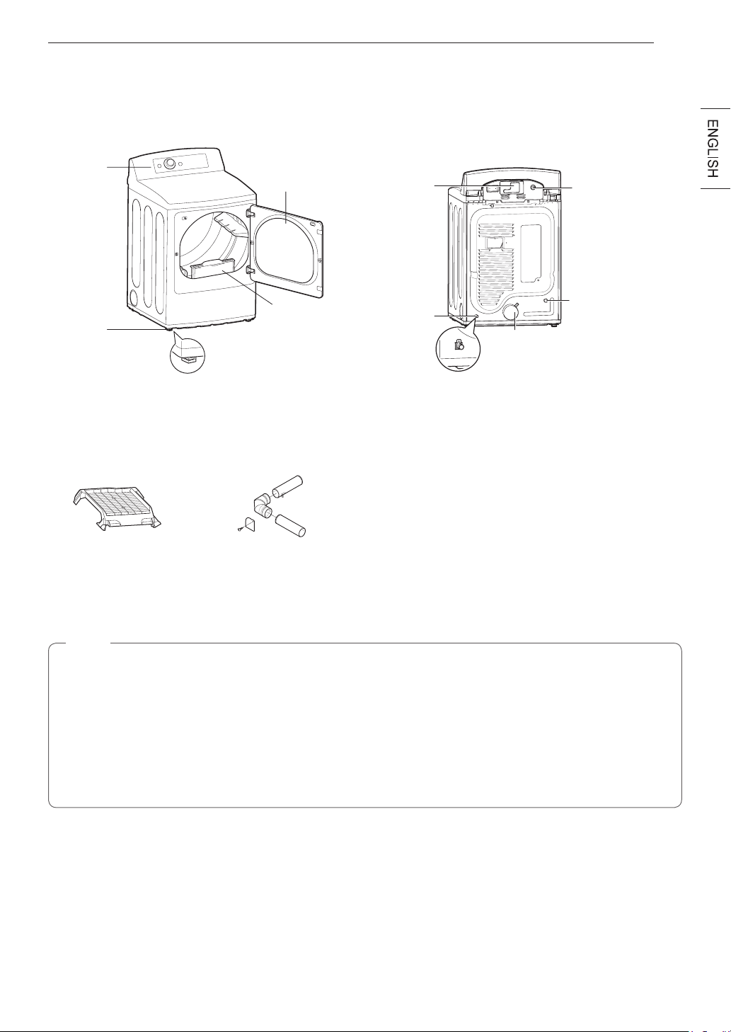
Parts
PRODUCT OVERVIEW
9
Control
panel
Leveling
feet
Accessories
Optional Accessories
Drying rack
(sold separately)
No. 3750EL0001C
Reversible
door
Lint lter
Side vent kit
(sold separately)
Kit No. 383EEL9001B
Terminal block
access panel
(electric models)
Gas connection
location
(gas models)
Power cord
location
(gas models)
Water inlet valve
(on some models)
Exhaust duct
outlet
NOTE
•Visit www.lg.com to purchase accessories.
•Contact LG Customer Service at 1-800-243-0000 (1-888-542-2623 in Canada) if any accessories are
missing.
•For your safety and for extended product life, use only authorized components. The manufacturer is not
responsible for product malfunction or accidents caused by the use of separately purchased unauthorized
components or parts.
•The images in this guide may be different from the actual components and accessories, which are subject
to change by the manufacturer without prior notice for product improvement purposes.
10
INSTALLATION
INSTALLATION
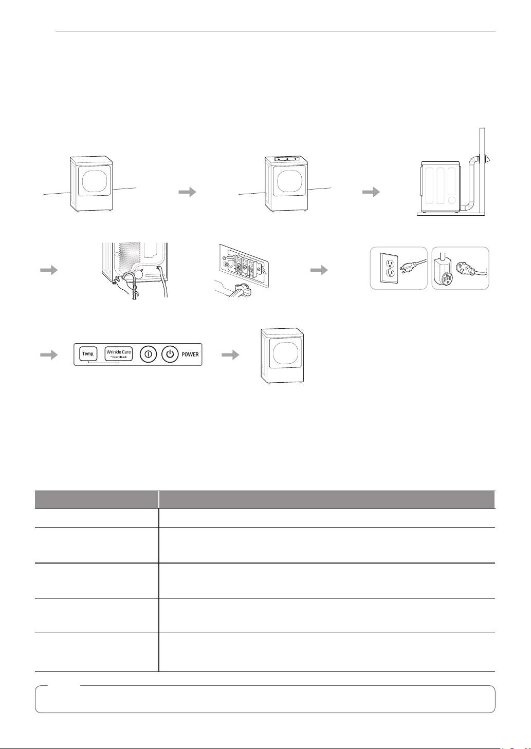
InstallationOverview
Please read the following installation instructions first after purchasing this product or transporting it to another
location.
Check and choose
the proper location
Connect gas dryers
Installation test Test run
Connect electric dryers
Level the dryer
Vent the dryer
Gas dryer Electric dryer
Plug in the power cord
Product Specifications
The appearance and specifications listed in this manual may vary due to constant product improvements.
Dryer Models DLE7100*, DLG7101*, DLE7150*, DLG7151*, DLE7000*, DLG7001*
Electricalrequirements
Please refer to the rating label regarding detailed information.
Gasrequirements
Dimensions
Net weight
Drying capacity
- Normal cycle
NOTE
Model numbers can be found on the cabinet inside the door.
NG: 4–10.5-inch WC
LP: 8–13-inch WC
27” (W) X 29 1/2” (D) X 44 1/2” (H), 50 1/4” (D with door open)
68.6 cm (W) X 75.0 cm (D) X 113.0 cm (H), 127.5 cm (D with door open)
Gas dryer : 118.6 lb (53.8 Kg)
Electric dryer : 114.9 lb (52.1 Kg)
IEC 7.3 cu.ft. (22.5 lb/10.2 kg)

INSTALLATION
11
InstallationLocationRequirements
WARNING
Read all installation instructions completely before installing and operating the dryer! It is important that you
review this entire manual before installing and using the dryer. Detailed instructions concerning electrical
connections, gas connections, and exhaust requirements are provided on the following pages.
The installation requires:
•A location that allows for proper exhaust installation. A gas dryer must be exhausted to the outdoors. See
Venting the Dryer.
•A grounded electrical outlet located within 2 ft. (61 cm) of either side of the dryer. See Connecting Electric
Dryers .
•A sturdy floor to support the total dryer weight of 200 lb (90.7 kg). The combined weight of a companion
appliance should also be considered.
•No other fuel-burning appliance can be installed in the same closet as a dryer.
Do not operate the dryer at temperatures below 45 °F (7 °C). At lower temperatures, the dryer might not shut off
at the end of an automatic cycle. This can result in longer drying times. The dryer must not be installed or stored
in an area where it will be exposed to water and/or weather. Check code requirements. Some codes limit, or do
not permit, installation of the dryer in garages, mobile homes or sleeping quarters. Contact your local building
inspector.
NOTE
•The floor must be level, with a maximum slope of 1 inch (2.5 cm) under the entire dryer.
Clothes may not tumble properly, and automatic sensor cycles may not operate correctly if dryer is not
level.
•For a garage installation, you will need to place the dryer at least 18 inches (46 cm) above the floor. The
standard pedestal is 15 inches (38.1 cm). You will need 18 inches (46 cm) from the garage floor to the
bottom of the dryer.
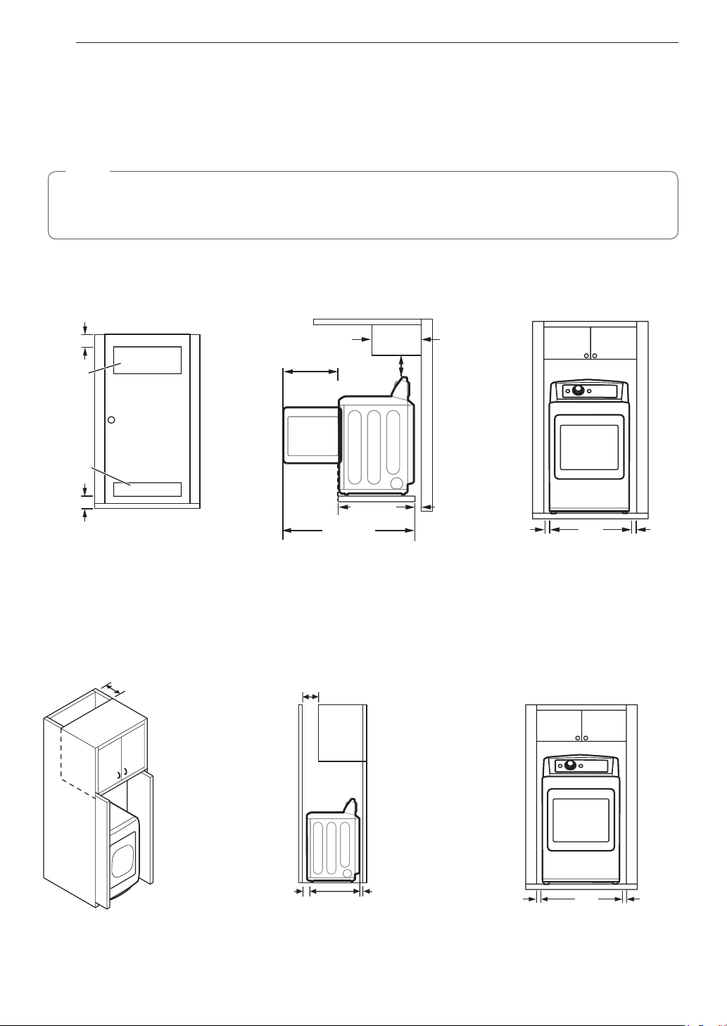
Clearances
Installation Spacing for Recessed Area or Closet Installation
The following spacing dimensions are recommended for this dryer. This dryer has been tested for clearances of
1 inch (2.5 cm) on the sides and rear. Recommended clearances should be considered for the following reasons:
•Additional clearances should be considered for ease of installation and servicing.
•Additional clearances might be required for wall, door and floor moldings.
•Additional clearances should be considered on all sides of the dryer to reduce noise transfer.
For closet installation, with a door, minimum ventilation openings in the top and bottom of the door are
required. Louvered doors with equivalent ventilation openings are acceptable.
•Companion appliance spacing should also be considered.
12
INSTALLATION
ClosetVentilationRequirements
Closets with doors must have both an upper and lower vent to prevent heat and moisture buildup in the closet.
One upper vent opening with a minimum opening of 48 sq. in. (310 cm2) must be installed no lower than 6 feet
above the floor. One lower vent opening with a minimum opening of 24 sq. in. (155 cm2) must be installed no
more than one foot above the floor. Install vent grills in the door or cut down the door at the top and bottom to
form openings. Louvered doors with equivalent ventilation openings are also acceptable.
NOTE
There should be at least a little space around the dryer (or any other appliance) to eliminate the transfer of
vibration from one appliance to another. If there is enough vibration, it could cause appliances to make noise
or come into contact, causing paint damage and further increasing noise.
Installation Spacing for Recessed Area or Closet
3"
(7.6 cm)
14" max.*
(35.6 cm)
18" min.
(45.7 cm)
2
48 in.
(310 cm2)
1
21
/4"
(54 cm)
2
24 in.
(155 cm2)
1
/2"
29
(75.0 cm)
1
/4"
50
(127.5 cm)
1"
(2.5 cm)
27"
(68.6 cm)
3"
(7.6 cm)
Closet Door Vent
Requirements
* Required spacing
Installation Spacing for Cabinet
For cabinet installation with a door, minimum ventilation openings in the top of the cabinet are required.
* Required spacing
7"* (17.8 cm)
7"* (17.8 cm)
1"
(2.5 cm)
5"
(12.7 cm)
*
1
/2"
29
(75.0 cm)
1"
*
(2.5 cm)
(2.5 cm)
1"
27"
(68.6 cm)
1"
(2.5 cm)
INSTALLATION
13
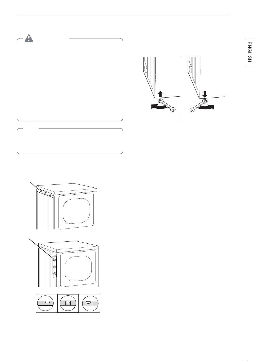
LevelingtheDryer
WARNING
To reduce the risk of injury to persons, adhere
to all industry recommended safety procedures
including the use of long-sleeved gloves and
safety glasses. Failure to follow this warning may
result in serious injury or death.
•The appliance is heavy. Two or more people
are required when installing the dryer. Failure to
follow this warning may result in serious injury
or death.
•To ensure that the dryer provides optimal drying
performance, it must be level. To minimize
vibration, noise, and unwanted movement, the
floor must be a perfectly level, solid surface.
NOTE
Adjust the leveling feet only as far as necessary
to level the dryer. Extending the leveling feet more
than necessary may cause the dryer to vibrate.
Position the dryer in the final location. Check
1
levelness of dryer from side to side. Repeat from
front to back.
Place level here
Use an adjustable wrench to turn the leveling
2
feet. Unscrew the legs to raise the dryer or
screw in the legs to lower it. Raise or lower with
the leveling feet until the dryer is level from side
to side and front to back. Make sure that all four
leveling feet are in firm contact with the floor.
If you are installing the dryer on the optional pedestal,
you must use the leveling feet on the pedestal to level the
dryer. The dryer leveling feet should be fully retracted.
Place level here
Not Level Not LevelLevel
14
INSTALLATION
ReversingtheDoor
WARNING
THE DRYER DOOR IS VERY LARGE AND
HEAVY. Failure to follow the instructions below
can result in damage to the dryer, property
damage or injury to persons.
•To avoid damage to the dryer or the door,
support the door with a stool or box that fits
under the door, or have an assistant support
the weight of the door.
•Avoid dropping the door to avoid damage to the
door or the floor.
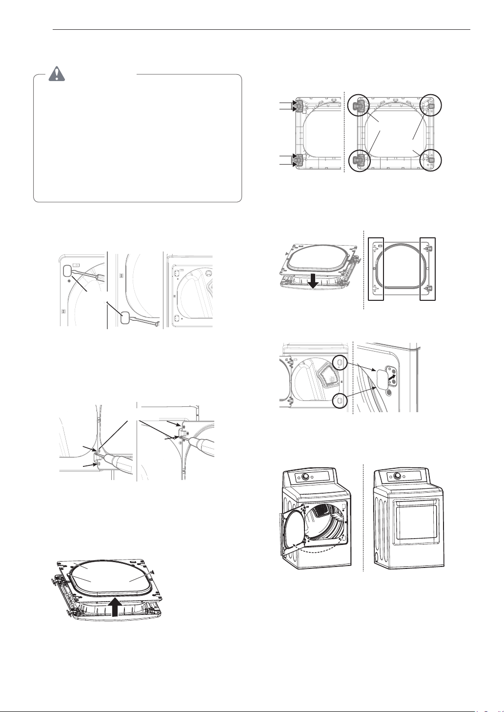
Open the door and remove the two plastic hole
1
caps on the catch side by gently prying up with a
flat blade screwdriver. Save these for step 6.
Hole cap
Remove the 4 screws securing the hinges to
4
the door frame. Remove the two plastic cover
caps. Reinstall the hinges and cover caps on the
opposite sides from which they were removed.
Hinge
assembly
Cover cap
With the hinges and cover caps in the new
5
locations, remount the inner door frame onto the
outer door frame with the screws removed in
step 3 above.
Reinstall the door with the screws from steps 1,2.
6
While supporting the door, remove the 4 screws,
2
two from each hinge. Set the door aside face
down on a protected surface to prevent damage
to the door or the work surface.
Hinge screw
With the door on a protected surface, remove all
3
screws on each side of the door and lift off the
inner door frame using a flat blade screwdriver.
Remove the latch hook and blank and move
them to the opposite side.
Inner door
frame
Latch hook
Test the swing of the door to make sure the
7
hinges and latch are properly aligned and that
the door closes and latches correctly.
Swing Door
INSTALLATION
15
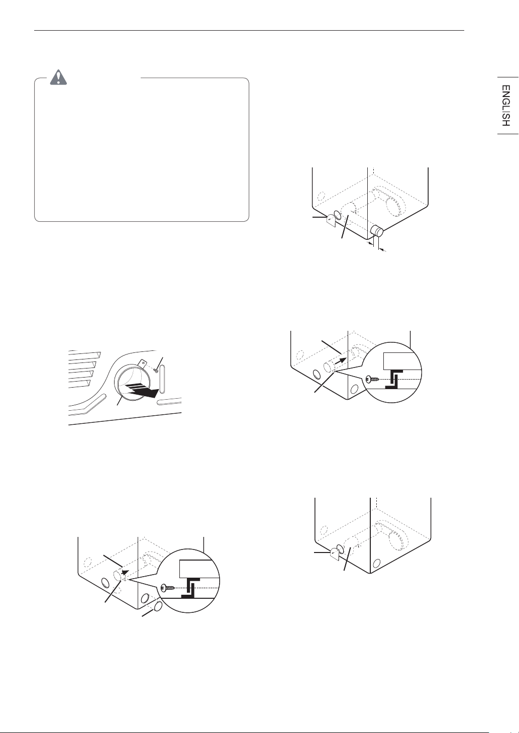
Installing the Side Vent Kit
WARNING
•Use a heavy metal vent.
•Do not use plastic or thin foil ducts.
•Clean old ducts before installing this dryer.
•To reduce the risk of injury to persons, adhere
to all industry recommended safety procedures
including the use of long-sleeved gloves and
safety glasses.
•Failure to follow all of the safety warnings in this
manual could result in property damage, injury
to persons, or death.
The dryer is shipped to vent to the rear. It can also
be configured to vent to the bottom or side (right-side
venting is not available on gas models).
An adapter kit, part number 383EEL9001B, may be
purchased from an LG retailer. This kit contains the
necessary duct components to change the dryer vent
location.
Remove the rear exhaust duct retaining screw.
1
Pull out the exhaust duct.
Retaining Screw
Preassemble a 4-inch (10.2 cm) elbow to the
3
next 4-inch (10.2 cm) duct section, and secure
all joints with duct tape. Be sure that the male
end of the elbow faces AWAY from the dryer.
Insert the elbow/duct assembly through the
side opening and press it onto the adapter duct.
Secure it in place with duct tape. Be sure that
the male end of the duct protrudes 1½ inches
(3.8 cm) to connect the remaining ductwork.
Attach the cover plate to the back of the dryer
with the included screw.
Cover
Plate
Elbow
"
1
½
(3.8 cm)
Option 2: Bottom Venting
Press the adapter duct onto the blower housing
2
and secure it to the base of the dryer as shown.
Adapter
Duct
Rear Exhaust
Duct
Option 1: Side Venting
Press the tabs on the knockout and carefully
2
remove the knockout for the desired vent
opening (right-side venting is not available on
gas models). Press the adapter duct onto the
blower housing and secure to the base of the
dryer as shown.
Adapter
Duct
Bracket
Knockout
Bracket
Insert the 4-inch (10.2 cm) elbow through the
3
rear opening and press it onto the adapter duct.
Be sure that the male end of the elbow faces
down through the hole in the bottom of the
dryer. Secure it in place with duct tape. Attach
the cover plate to the back of the dryer with the
included screw.
Cover
Plate
Elbow
 Loading...