

Page 1
C
E
R
T
I
F
I
E
D
D
E
S
I
G
N
Before beginning installation, read these
instructions carefully. This will simplify installation
and ensure that the dryer is installed correctly and
safely. Leave these instructions near the dryer
after installation for future reference.
To contact LG Electronics, 24 hours a day,
7 days a week:
1-800-243-0000
Or visit us on the Web at: us.lge.com
Número telefónico de LG Electronics, las 24
horas del día, 7 días a la semana:
1-800-243-0000
O visítenos en la Web en: us.lge.com
To contact LG Electronics, 24 hours a day,
7 days a week :
1-888-LGCANADA
Or visit us on the Web at : ca.lge.com
Pour contacter LG Electronics, 24 heures
Par jour, 7 jours par semaine :
1-888-LGCANADA
Ou visitez notre site Web a l’addresse :
ca.lge.com
Antes de comenzar la instalación, lea atentamente
estas instrucciones. Esto simplificará la instalación
y asegurará que la secadora está instalada
en forma correcta y segura. Conserve estas
instrucciones cerca de la secadora luego de la
instalación para futuras consultas.
Avant de commencer à installer votre sécheuse, lisez
attentivement ces instructions. Cela simplifiera votre
installation et assurera que la sécheuse est installée
correctement et en toute sécurité. Conservez ces
instructions à proximité de la sécheuse après son
installation, pour référence future.
DLE2101W
DLE2101R
DLE2101S
DLE2101L
DLG2102W
DLG2102R
DLG2102S
DLG2102L
Page 2
IMPORTANT SAFETY INSTRUCTIONS
Basic Safety Precautions .......................................3
What to Do if You Smell Gas .................................. 4
Grounding Instructions ........................................... 5
Safety Instructions for Installation ...................... 5, 6
Safety Instructions for Connecting Electricity ....... 7
PARTS AND FEATURES
Key Parts and Components ................................... 8
THANK YOU!
Congratulations on your purchase
and welcome to the LG family. Your
INSTALLATION INSTRUCTIONS
Choose the Proper Location .................................. 9
Clearances ............................................................. 9
Installation With Optional
Pedestal Base or Stacking Kit .............................. 10
Leveling the Dryer ................................................ 11
Reversing the Door Swing .................................... 11
Changing the Dryer Vent Location ....................... 12
Venting the Dryer ............................................ 13, 14
Connecting Gas Dryers .................................. 15, 16
Connecting Electric Dryers ..............................17-21
Special Requirements for Manufactured
or Mobile Homes .................................................. 22
Final Installation Check .......................................22
HOW TO USE
Sorting Loads ....................................................... 23
Loading the Dryer ................................................. 23
Check the Lint Filter Before Every Load ............... 23
Control Panel Features ......................................... 24
Cycle Guide .......................................................... 25
The LED Display ................................................... 26
Operating the Dryer .............................................. 27
Cycle Setting Buttons .......................................... 28
Custom Program .................................................. 28
Cycle Option Buttons .......................................... 29
USER-MAINTENANCE INSTRUCTIONS
Regular Cleaning .................................................. 30
new LG Dryer combines the most
advanced drying sensor technology
with simple operation and high
efficiency. By following the
operating and care instructions
in this manual, your dryer will
provide you with many years of
reliable service.
Product Registration Information
Model:
Serial Number:
Date of Purchase:
The model and serial number can be located on the rating
plate inside the front door.
TROUBLESHOOTING
Before Calling for Service ...............................31, 32
SPECIFICATIONS/OPTIONAL
ACCESSORIES
Key Dimensions and Specifi cations ..................... 33
Optional Accessories ........................................... 33
Pedestal Installation ....................................... 34, 35
Stacking Kit Installation .................................. 36, 37
WARRANTY ............................................. 38, 39
2
Page 3
READ ALL INSTRUCTIONS BEFORE USE
wWARNING For your safety, the information in this manual must be
followed to minimize the risk of fire or explosion, electric shock, or to prevent
property damage, personal injury, or loss of life.
Your Safety and the safety of others is very important.
We have provided many important safety messages in this manual and on your appliance. Always read
and obey all safety messages.
This is the safety alert symbol.
This symbol alerts you to potential hazards that can kill or hurt you and others.
All safety messages will follow the safety alert symbol and either the word DANGER or WARNING.
These words mean:
wDANGER: You can be killed or seriously injured if you don’t immediately follow instructions.
wWARNING: You can be killed or seriously injured if you don’t follow instructions.
All safety messages will tell you what the potential hazard is, tell you how to reduce the chance of
injury, and tell you what can happen if the instructions are not followed.
BASIC SAFETY PRECAUTIONS
wWARNING: To reduce the risk of fire, electric shock, or injury to persons when using this
appliance, follow basic precautions, including the following:
• Read all instructions before using the dryer.
• Before use, the dryer must be properly installed
as described in this manual.
• Do not place items exposed to cooking oils in
your dryer. Items contaminated with cooking
oils may contribute to a chemical reaction that
could cause a load to catch fire.
• Do not dry articles that have been previously
cleaned in, washed in, soaked in, or spotted
with gasoline, dry-cleaning solvents, or other
flammable or explosive substances as they give
off vapors that could ignite or explode.
• Do not reach into the dryer if the drum or any
other part is moving.
• Do not repair or replace any part of the dryer
or attempt any servicing unless specifically
recommended in this Use and Care Guide or
in published user-repair instructions that you
understand and have the skills to carry out.
• Do not tamper with controls.
• Before the dryer is removed from service or
discarded, remove the door to the drying
compartment.
• Do not allow children to play on or in the dryer.
Close supervision of children is necessary when
the dryer is used near children.
• Do not use fabric softeners or products to
eliminate static unless recommended by the
manufacturer of the fabric softener or product.
• Do not use heat to dry articles containing
foam rubber or similarly textured rubber-like
materials.
• Keep area around the exhaust opening and
adjacent surrounding areas free from the
accumulation of lint, dust, and dirt.
• The interior of the dryer and exhaust vent
should be cleaned periodically by qualified
service personnel.
• Do not install or store the dryer where it will be
exposed to the weather.
• Always check the inside of the dryer for foreign
objects.
• Clean lint screen before or after each load.
3
Page 4

READ ALL INSTRUCTIONS BEFORE USE
wWARNING For your safety, the information in this manual must be
followed to minimize the risk of fi re or explosion, electric shock, or to prevent
property damage, personal injury, or loss of life.
• Do not store or use gasoline or other
fl ammable vapors and liquids in the
vicinity of this appliance or any other
appliances.
• Installation and service must be
performed by a qualifi ed installer,
service agency, or the gas supplier.
WHAT TO DO IF YOU SMELL GAS:
1. Do not try to light a match or cigarette,
or turn on any gas or electrical
appliance.
2. Do not touch any electrical switches.
Do not use any phone in your building.
3. Clear the room, building, or area of all
occupants.
4. Immediately call your gas supplier
from a neighbor’s phone. Follow the
gas supplier’s instructions carefully.
5. If you cannot reach your gas
supplier, call the fi re department.
4
Page 5
READ ALL INSTRUCTIONS BEFORE USE
wWARNING For your safety, the information in this manual must be
followed to minimize the risk of fire or explosion, electric shock, or to prevent
property damage, personal injury, or loss of life.
GROUNDING INSTRUCTIONS
This appliance must be grounded. In the event
of malfunction or breakdown, grounding will
reduce the risk of electric shock by providing
a path of least resistance for electric current.
This appliance must be equipped with a cord
having an equipment-grounding conductor and
a grounding plug. The plug must be plugged into
an appropriate outlet that is properly installed and
grounded in accordance with all local codes and
ordinances.
wWARNING — Improper
connection of the equipment-grounding
conductor can result in a risk of electric shock.
Check with a qualified electrician or service
person if you are in doubt as to whether the
appliance is properly grounded.
Do not modify the plug provided with the
appliance. If it will not fit the outlet, have a proper
outlet installed by a qualified electrician.
This appliance must be connected to a grounded
metal, permanent wiring system or an equipmentgrounding conductor must be run with the circuit
conductors and connected to the equipmentgrounding terminal or lead on the appliance.
Electrical shock can result if the dryer is not
properly grounded.
SAFETY INSTRUCTIONS FOR INSTALLATION
wWARNING: To reduce the risk of fire, electric shock, or injury to persons when using this
appliance, follow basic precautions, including the following:
• Properly ground dryer to conform with all
governing codes and ordinances. Follow
details in the installation instructions. Electrical
shock can result if the dryer is not properly
grounded.
• Before use, the dryer must be properly
installed as described in this manual.
Electrical shock can result if the dryer is not
properly grounded.
• Install and store the dryer where it will not be
exposed to temperatures below freezing or
exposed to the weather.
• All repairs and servicing must be performed
by an authorized servicer unless specifically
recommended in this Owner’s Guide. Use
only authorized factory parts. Failure to follow
this warning can cause serious injury, fire,
electrical shock or death.
•
To reduce the risk of electric shock, do not
install the dryer in humid spaces. Failure to
follow this warning can cause serious injury, fire,
electrical shock, or death.
• Connect to a properly rated, protected,
and sized power circuit to avoid electrical
overload. Improper power circuit can melt,
creating electrical shock and/or fire hazard.
• Remove all packing items and dispose of all
shipping materials properly. Failure to do so
can result in death, explosion, fire, or burns.
• Place dryer at least 18 in. above the floor
for a garage installation. Failure to do so can
result in death, explosion, fire, or burns.
• Keep all packaging from children. Packaging
material can be dangerous for children. There is
a risk of suffocation.
5
Page 6

READ ALL INSTRUCTIONS BEFORE USE
wWARNING For your safety, the information in this manual must be
followed to minimize the risk of fi re or explosion, electric shock, or to prevent
property damage, personal injury, or loss of life.
SAFETY INSTRUCTIONS FOR INSTALLATION
Exhaust/Ducting:
• Gas dryers MUST be exhausted to the
outside. Failure to follow these instructions
can result in fi re or death.
• The dryer exhaust system must be exhausted
to the outside of the dwelling. If the dryer is
not exhausted outdoors, some fi ne lint and
large amounts of moisture will be expelled
into the laundry area. An accumulation of
lint in any area of the home can create a health
and fi re hazard.
• Use only rigid metal or fl exible metal 4-in.
diameter ductwork inside the dryer cabinet
or for exhausting to the outside. Use of
plastic or other combustible ductwork can
cause a fi re. Punctured ductwork can cause
a fi re if it collapses or becomes otherwise
restricted in use or during installation.
• Ductwork is not provided with the dryer, and
you should obtain the necessary ductwork
locally. The end cap should have hinged
dampers to prevent backdraft when the dryer
is not in use. Failure to follow these instructions
can result in fi re or death.
• The exhaust duct must be 4 in. (10 cm) in
diameter with no obstructions. The exhaust
duct should be kept as short as possible.
Make sure to clean any old ducts before
installing your new dryer. Failure to follow
these instructions can result in fi re or death.
• Rigid or semi rigid metal ducting is
recommended for use between the
dryer and the wall. In special installations
when it is impossible to make a connection
with the above recommendations, a ULlisted fl exible metal transition duct may be
used between the dryer and wall connection
only. The use of this ducting will affect drying
time. Failure to follow these instructions can
result in fi re or death.
• DO NOT use sheet metal screws or other
fasteners which extend into the duct that
could catch lint and reduce the effi ciency
of the exhaust system. Secure all joints with
duct tape. For complete details, follow the
Installation Instructions. Failure to follow these
instructions can result in fi re or death.
6
Page 7

READ ALL INSTRUCTIONS BEFORE USE
wWARNING For your safety, the information in this manual must be
followed to minimize the risk of fire or explosion, electric shock, or to prevent
property damage, personal injury, or loss of life.
SAFETY INSTRUCTIONS FOR CONNECTING ELECTRICITY
wWARNING: To reduce the risk of fire, electric shock, or injury to persons when using this
appliance, follow basic precautions, including the following:
• Do not, under any circumstances, cut or
remove the ground prong from the power
cord. To prevent personal injury or damage to
the dryer, the electrical power cord must be
plugged into a properly grounded outlet.
• For personal safety, this dryer must be
properly grounded. Failure to do so can result
in electrical shock or injury.
• Refer to the installation instructions in this
manual for specific electrical requirements
for your model. Failure to follow these
instructions can create an electrical shock
hazard and/or a fire hazard.
• This dryer must be plugged into a properly
grounded outlet. Electrical shock can result if
the dryer is not properly grounded. Have the
wall outlet and circuit checked by a qualified
electrician to make sure the outlet is properly
grounded. Failure to follow these instructions
can create an electrical shock hazard and/or a
fire hazard.
• The dryer should always be plugged into
its own individual electrical outlet which
has a voltage rating that matches the rating
plate. This provides the best performance
and also prevents overloading house wiring
circuits which could cause a fire hazard from
overheated wires.
• Never unplug your dryer by pulling on the
power cord. Always grip plug firmly and pull
straight out from the outlet. The power cord
can be damaged, resulting in a risk of fire and
electrical shock.
• Repair or replace immediately all power
cords that have become frayed or otherwise
damaged. Do not use a cord that shows
cracks or abrasion damage along its length
or at either end. The power cord can melt,
creating electrical shock and/or fire hazard.
• When installing or moving the dryer, be
careful not to pinch, crush, or damage
the power cord. This will prevent injury and
prevent damage to the dryer from fire and
electrical shock.
SAVE THESE INSTRUCTIONS
7
Page 8
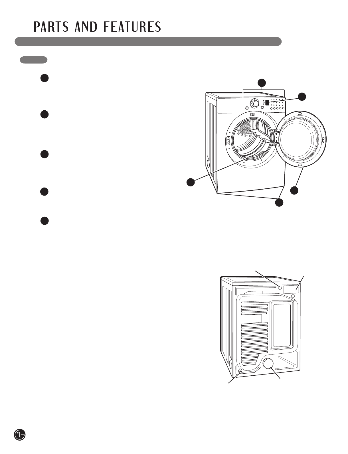
KEY PARTS AND COMPONENTS
EASY-TO-USE CONTROL PANEL
1
Rotate the Cycle Selector Knob to select the
desired dry cycle. Add cycle options or adjust
settings with the touch of a button.
2
LED DISPLAY
The easy-to-read LED display shows cycle
options and information and provides status
messages during operation.
3
EASY-ACCESS REVERSIBLE DOOR
Wide-opening door provides easy access for
loading and unloading. Door swing can be
reversed to adjust for installation location.
FRONT-MOUNT LINT FILTER
4
Front-mounted lint filter allows for easy access
and cleaning after every load.
5
LEVELING FEET
Four leveling feet (two in the front, and two in
the back) adjust to improve dryer stability on
uneven floors.
1
2
4
3
5
Power Cord Location
(Gas Models)
Gas
Connection
Location
(Gas Models)
Terminal Block
Access Panel
(Electric Models)
Exhaust Duct
Outlet
Rear of Dryer
8
Page 9
IMPORTANT: Read all installation instructions completely before
24 in.
2
(155 cm2)
3"
(7.6 cm)
3"
(7.6 cm)
48 in.
2
(310 cm2)
installing and operating your dryer!
It is important that you review this entire manual before installing and using your dryer. Detailed instructions
concerning electrical connections, gas connections, and exhaust requirements are provided on the
following pages.
CHOOSE THE PROPER LOCATION
• Store and install the dryer where it will not be
exposed to temperatures below freezing or
exposed to outdoor weather conditions.
• Choose a location with a solid, level floor.
• If the dryer is being installed in a garage,
place the dryer at least 18 in. (46 cm) above
the floor.
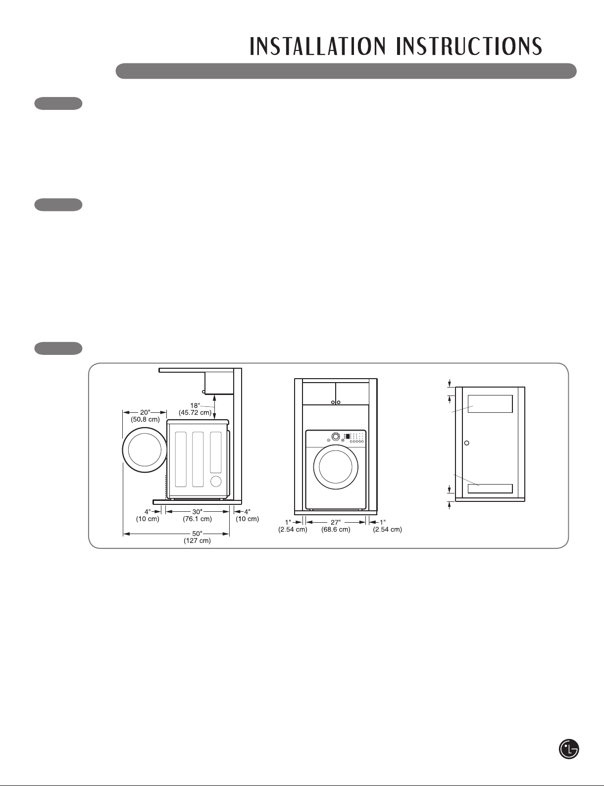
CLEARANCES
• Properly ground dryer to conform with all
governing codes and ordinances.
• To reduce the risk of electric shock, do not
install the dryer in damp or wet locations.
• If you are installing your dryer in a manufactured
or mobile home, please refer to the section
Special Requirements for Manufactured or
Mobile Homes.
Closet Door Vent
Requirements
• Most installations require a minimum 5½ in.
(14 cm) clearance behind the dryer for the
exhaust ducting.
• Allow minimum clearances of at least 1 in.
(2.5 cm) on the sides and back to minimize
vibration and noise.
• Allowing additional clearance for installation and
Additional Instructions for closet installations:
• The closet door must allow for sufficient airflow.
Refer to the diagram above for minimum vent
opening requirements. A louvered door is also
acceptable.
• Make sure that there is at least 18 in. (46 cm) of
clearance above the dryer.
servicing is recommended.
• Be sure to allow for wall, door, or floor moldings
that may increase the required clearances.
• Allow at least 24 in. (61 cm) in front of the dryer
to open the door.
9
Page 10
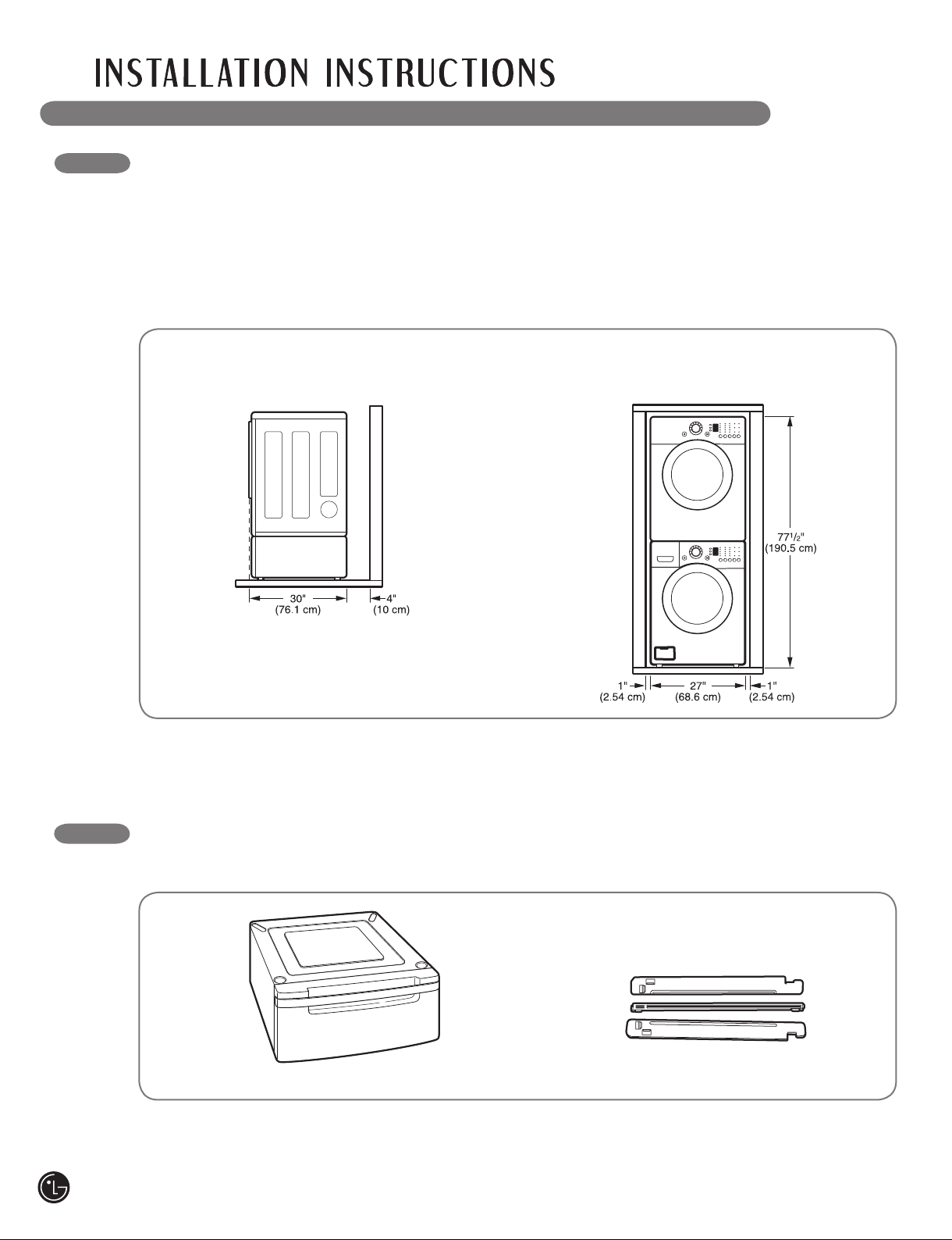
INSTALLATION WITH OPTIONAL PEDESTAL BASE OR STACKING KIT
IMPORTANT: If you are installing your dryer
using an optional pedestal base or stacking
kit, please refer to Optional Accessories in this
manual or to the instructions for your pedestal
or stacking kit before proceeding with the
installation.
Required Dimensions for Installation
With Pedestal
Required Dimensions for Installation
With Stacking Kit
10
OPTIONAL ACCESSORIES
For these and other LG products, contact your local LG dealer, or visit our Web site at ca.lge.com
Pedestal (sold separately)
Stacking Kit (sold separately)
Page 11
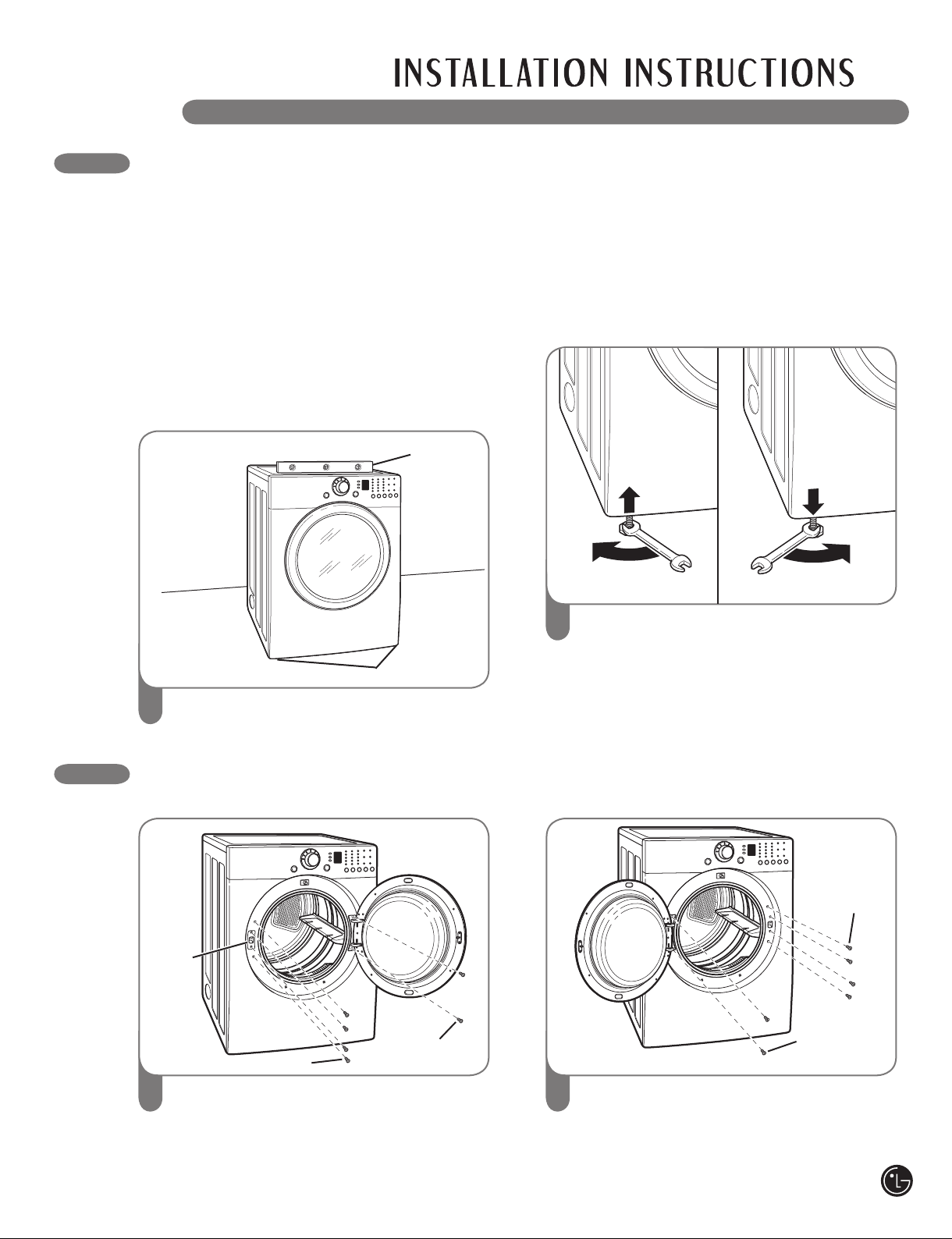
LEVELING THE DRYER
wWARNING
• Wear gloves during installation.
•
Failure to follow these instructions can result in injury.
To ensure that the dryer provides optimal drying
performance, it must be level. To minimize
vibration, noise, and unwanted movement, the
floor must be a perfectly level, solid surface.
NOTE: Adjust the leveling feet only as far as
necessary to level the dryer. Extending the
leveling feet more than necessary can cause
the dryer to vibrate.
Level
Leveling Feet
Position the dryer in the final location. Place
1
a level across the top of the dryer.
• All four leveling feet must rest solidly on the
floor. Gently push on the top corners of the
dryer to make sure that the dryer does not
rock from corner to corner.
If you are installing the dryer on the optional
pedestal, you must use the leveling feet on the
pedestal to level the dryer. The dryer leveling feet
should be fully retracted.
2
Use an adjustable wrench to turn the leveling
feet. Turn clockwise to raise the dryer or
counterclockwise to lower it. Raise or lower
the leveling feet until dryer is level from
side to side and front to back.
Make sure that all 4 leveling feet are in firm
contact with the floor.
REVERSING THE DOOR SWING
The swing of the dryer door can be reversed to fit your installation location.
Door
Latch
Hinge
Latch Screws
Open the dryer door. Using a Phillips
1 2
screwdriver, remove the 2 screws that secure
the door hinge to the dryer door opening.
Remove the 4 screws from the latch side of the
dryer door opening, and remove the door latch.
Screws
Turn the door around so the hinge is
reversed, and reattach the door using the
2 screws previously removed. Reinstall the
door latch and the 4 screws.
Test the door swing to make sure the door
moves freely and latches securely.
Latch
Screws
Hinge
Screws
11
Page 12
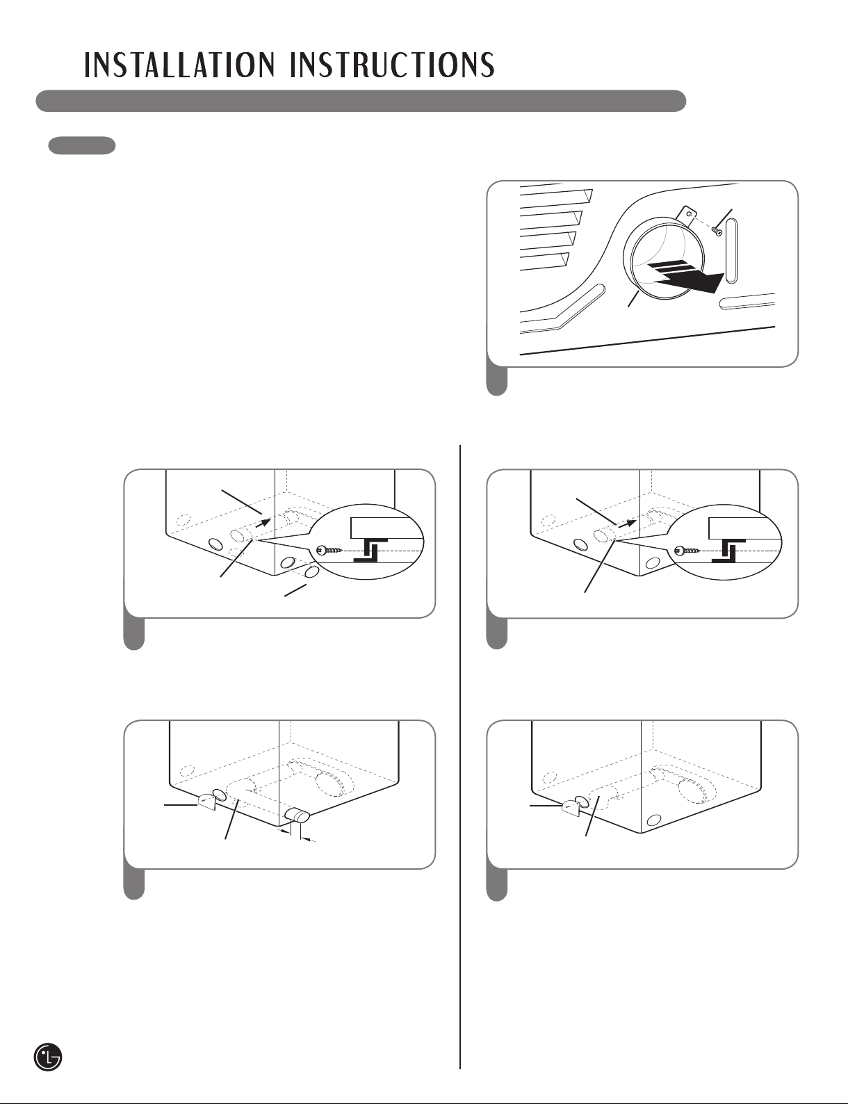
CHANGING THE DRYER VENT LOCATION
11/2"
(3.8 cm)
wWARNING
• Use a heavy metal vent.
• Do not use plastic or thin foil duct.
• Clean old ducts before installing this dryer.
• Wear gloves during installation.
• Failure to follow these instructions can result in
death or fi re.
Your new dryer is shipped to vent to the rear.
It can also be configured to vent to the bottom
or side (right-side venting is not available on
gas models).
An adapter kit, part number 383EEL9001B,
may be purchased from your LG retailer. This
kit contains the necessary duct components
to change the dryer vent location.
OPTION 1: Side Venting
Adapter
duct
Bracket
Knockout
Rear
Exhaust Duct
1
Remove the rear exhaust duct retaining
1
screw. Pull out the exhaust duct.
OPTION 2: Bottom Venting
Adapter
Duct
Bracket
Retaining
Screw
12
2
Press the tabs on the knockout and carefully
remove the knockout for the desired vent
opening (right-side venting is not available on
gas models). Press the adapter duct onto the
blower housing and secure to the base of the
dryer as shown.
Cover
Plate
Elbow
3
Preassemble a 4-in. (10 cm) elbow to the next
4-in. (10 cm) duct section, and secure all joints
with duct tape. Be sure that the male end of
the elbow faces AWAY from the dryer.
Insert the elbow/duct assembly through the
side opening and press it onto the adapter
duct. Secure in place with duct tape.
Be sure that the male end of the duct
protrudes 1½ in. (3.8 cm) to connect the
remaining ductwork.
Attach cover plate to the back of the dryer with
included screw.
2
Press the adapter duct onto the blower
housing and secure to the base of the dryer
as shown.
Cover
Plate
Elbow
3
Insert the 4-in. (10 cm) elbow through the
rear opening and press it onto the adapter
duct. Be sure that the male end of the elbow
faces down through hole in the bottom of the
dryer. Secure in place with duct tape.
Attach the cover plate to the back of the
dryer with included screw.
Page 13

VENTING THE DRYER
wWARNING: To reduce the risk of fire, electric shock, or injury to persons when using this
appliance, follow basic precautions, including the following:
• Do not crush or collapse ductwork. Failure
to follow these instructions can result in fire
or death.
• Do not allow ductwork to rest on or
contact sharp objects. Failure to follow these
instructions can result in fire or death.
• If connecting to existing ductwork, make
sure it is suitable and clean before installing
the dryer. Failure to follow these instructions
can result in fire or death.
• Venting must conform to local building
codes. Failure to follow these instructions can
result in fire or death.
• Gas dryers MUST exhaust to the outdoors.
Failure to follow these instructions can result
in fire or death.
• Use only 4-in. (10 cm) rigid or flexible metal
ductwork inside the dryer cabinet and
for venting outside. Failure to follow these
instructions can result in fire or death.
• To reduce the risk of fire, combustion, or
accumulation of combustible gases, DO
NOT exhaust dryer air into an enclosed and
unventilated area, such as an attic, wall,
ceiling, crawl space, chimney, gas vent, or
concealed space of a building. Failure to
follow these instructions can result in fire
or death.
• To reduce the risk of fire, DO NOT exhaust
the dryer with plastic or thin foil ducting.
Failure to follow these instructions can result
in fire or death.
• The exhaust duct must be 4 in. (10 cm) in
diameter with no obstructions. The exhaust
duct should be kept as short as possible.
Make sure to clean any old ducts before
installing your new dryer. Failure to follow
these instructions can result in fire or death.
•
Rigid or semirigid metal ducting is
recommended for use between the dryer
and the wall. In special installations when
it is impossible to make a connection with
the above recommendations, a UL-listed
flexible metal transition duct may be used
between the dryer and wall connection only.
The use of this ducting will affect drying
time. Failure to follow these instructions can
result in fire or death.
• DO NOT use sheet metal screws or other
fasteners which extend into the duct that
could catch lint and reduce the efficiency
of the exhaust system. Secure all joints
with duct tape. Failure to follow these
instructions can result in fire or death.
• To maximize operating results, please
observe the duct length limitations noted in
the chart on page 14. Failure to follow these
instructions can result in fire or death.
• Ductwork is not provided with the dryer.
You should obtain the necessary ductwork
locally. The end cap should have hinged
dampers to prevent backdraft when the
dryer is not in use. Failure to follow these
instructions can result in fire or death.
13
Page 14
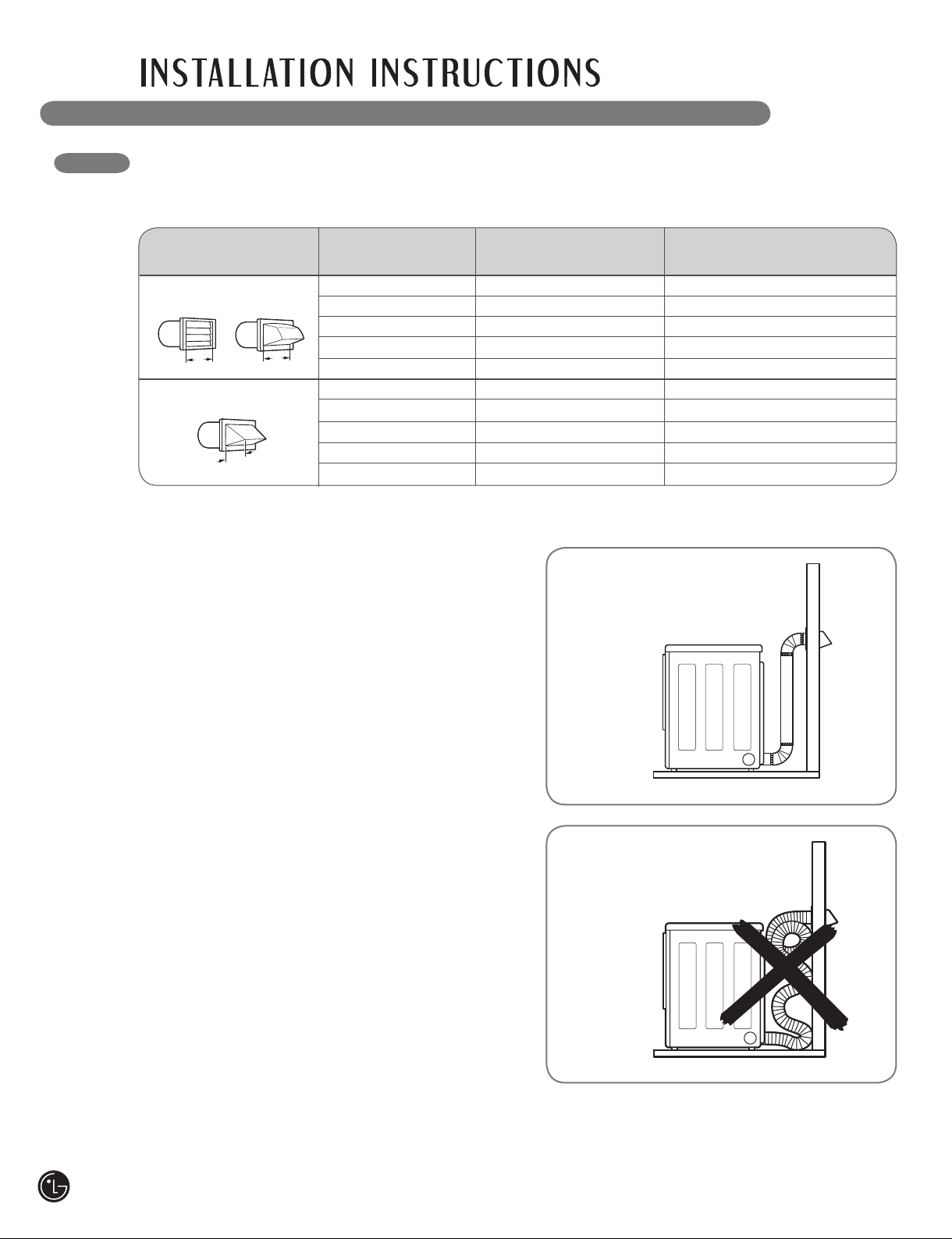
VENTING THE DRYER (cont.)
4"
(10.2 cm)
21/2"
(6.35 cm)
4"
(10.2 cm)
Ductwork
Number of Max. Length of 4-In. Dia. Max. Length of 4-In. Dia.
Wall Cap Type 90° Elbows Rigid Metal Duct Flexible Metal Duct
0 65 ft. (19.8 m) 45 ft. (13.7 m)
Recommended
1 55 ft. (16.8 m) 35 ft. (10.7 m)
2 47 ft. (13.7 m) 30 ft. (9.1 m)
3 36 ft. (11.0 m) 25 ft. (7.6 m)
4 28 ft. (8.5 m) 20 ft. (6.1 m)
0 55 ft. (16.8 m) 35 ft. (10.7 m)
Use Only for Short
2 41 ft. (12.5 m) 21 ft. (6.4 m)
3 30 ft. (9.1 m) 17 ft. (5.2 m)
4 22 ft. (6.7 m) 15 ft. (4.5 m)
NOTE: Deduct 6 ft. (1.8 m) for each additional elbow. It is not recommended to use more than four 90° elbows.
Run Installations
1 47 ft. (13.7 m) 27 ft. (8.1 m)
Routing and Connecting Ductwork
Follow the guidelines below to maximize drying
performance and reduce lint buildup and
condensation in the ductwork.
NOTE: Ductwork and fittings are NOT included
and must be purchased separately.
• Use 4-in. (10 cm) diameter rigid or semirigid
metal ductwork.
• The exhaust duct run should be as short as
possible.
• Use as few elbow joints as possible.
• The male end of each section of exhaust duct
must point away from the dryer.
• Use duct tape on all duct joints.
• Insulate ductwork that runs through unheated
areas in order to reduce condensation and lint
buildup on duct surfaces.
IMPORTANT: Failure to exhaust the dryer
correctly will void the dryer’s warranty.
Correct Venting
Incorrect Venting
14
Page 15

CONNECTING GAS DRYERS
wWARNING: To reduce the risk of fire, electric shock, or injury to persons when using this
appliance, follow basic precautions, including the following:
• Gas supply requirements:
As shipped from the factory, this dryer
is configured for use with natural gas.
It can be converted for use with LP
(Liquefied Propane) gas. Gas pressure
must not exceed 13 in. water column.
• A qualified service or gas company
technician must connect the dryer to the
gas service. Failure to do so can result in fire,
explosion, or death.
• Isolate the dryer from the gas supply system
by closing its individual manual shutoff
valve during any pressure testing of the
gas supply. Failure to do so can result in fire,
explosion, or death.
• Supply line requirements:
Your laundry room must have a rigid gas
supply line to your dryer. In the United
States, an individual manual shutoff valve
MUST be installed within at least 6 ft. (1.8 m)
of the dryer, in accordance with the National
Fuel Gas Code ANSI Z223.1. A 1/8-in. NPT
pipe plug must be installed. Failure to do so
can result in fire, explosion, or death.
• If using a rigid pipe, the rigid pipe should be
1/2-in. IPS. If acceptable under local codes
and ordinances and when acceptable to
your gas supplier, 3/8-in. approved tubing
may be used where lengths are less than 20
ft. (6.1 m). Larger tubing should be used for
lengths in excess of 20 ft. (6.1 m). Failure to
do so can result in fire, explosion, or death.
•
Connect the dryer to the type of gas shown
on the nameplate. Failure to do so can result
in fire, explosion, or death.
• To prevent contamination of the gas valve,
purge the gas supply of air and sediment
before connecting the gas supply to the
dryer. Before tightening the connection
between the gas supply and the dryer,
purge remaining air until the odor of gas is
detected. Failure to do so can result in fire,
explosion, or death.
• DO NOT use an open flame to inspect
for gas leaks. Use a noncorrosive leakdetection fluid. Failure to do so can result in
fire, explosion, or death.
• Use only a new AGA- or CSA-certified gas
supply line with flexible stainless steel
connectors. Failure to do so can result in fire,
explosion, or death.
• Securely tighten all gas connections. Failure
to do so can result in fire, explosion, or death.
• Use Teflon® tape or a pipe-joint compound
that is insoluble in Liquefied Petroleum (LP)
gas on all pipe threads. Failure to do so can
result in fire, explosion, or death.
• DO NOT attempt any disassembly of
the dryer; any disassembly requires the
attention and tools of an authorized and
qualified service person or company. Failure
to do so can result in fire, explosion, or death.
Electrical Requirements for Gas Models Only
wWARNING: To reduce the risk of fire, electric shock, or injury to persons when using this
appliance, follow basic precautions, including the following:
• Do not, under any circumstances, cut or
remove the third (ground) prong from the
power cord. Failure to follow this warning can
result in fire, explosion, or death.
• For personal safety, this dryer must be
properly grounded. Failure to follow this
warning can result in fire, explosion, or death.
• The power cord of this dryer is equipped with
a 3-prong (grounding) plug which mates with
a standard 3-prong (grounding) wall outlet
to minimize the possibility of electric shock
hazard from this appliance. Failure to follow
this warning can result in fire, explosion,
or death.
• This dryer must be plugged into a
120-VAC, 60-Hz. grounded outlet protected
by a 15-ampere fuse or circuit breaker.
Failure to follow this warning can result in fire,
explosion, or death.
• Where a standard 2-prong wall outlet
is encountered, it is your personal
responsibility and obligation to have it
replaced with a properly grounded 3-prong
wall outlet. Failure to follow this warning can
result in fire, explosion, or death.
15
Page 16
CONNECTING GAS DRYERS (cont.)
wWARNING: To reduce the risk of fire, electric shock, or injury to persons when using this
appliance, follow basic precautions, including the following:
• Installation and service must be performed
by a qualifi ed installer, service agency, or the
gas supplier. Failure to do so can result in fi re,
explosion, or death.
• Use only a new stainless steel fl exible
connector and a new AGA-certifi ed
connector. Failure to do so can result in fi re,
explosion, or death.
• A gas shutoff valve must be installed within
6 ft. (1.8 m) of the dryer. Failure to do so can
result in fi re, explosion, or death.
• The dryer is confi gured for Natural Gas when
shipped from the factory. Make sure that the
dryer is equipped with the correct burner
nozzle for the type of gas being used (Natural
Gas or Liquefi ed Petroleum). Failure to do so
can result in fi re, explosion, or death.
• If necessary, the correct nozzle (for the LP
nozzle kit order part number 4948EL4002B)
should be installed by a qualifi ed technician
and the change should be noted on the dryer.
Failure to do so can result in fi re, explosion,
or death.
• All connections must be in accordance with
local codes and regulations. Failure to do so
can result in fi re, explosion, or death.
• Gas dryers MUST exhaust to the outdoors.
Failure to do so can result in fi re, explosion,
or death.
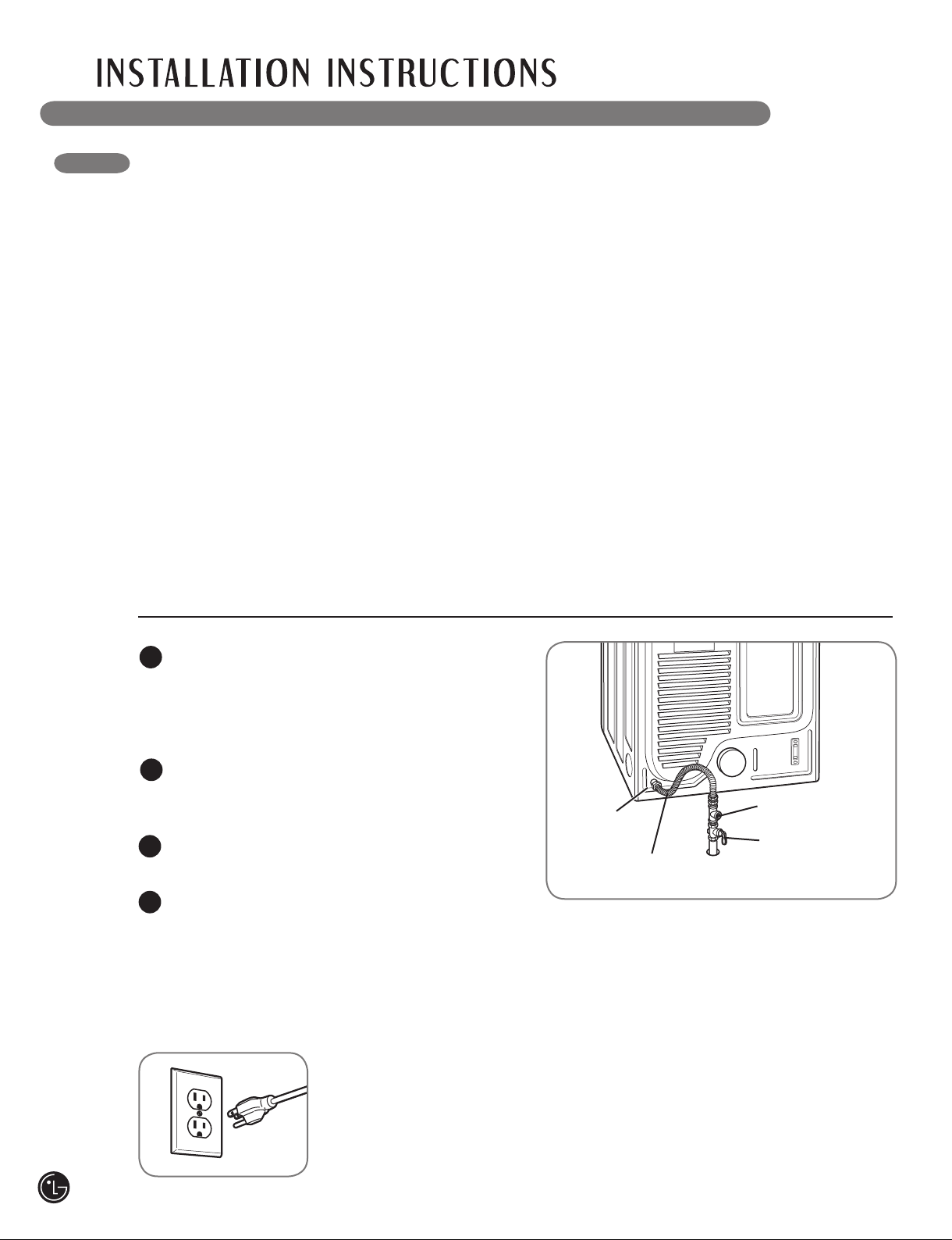
Connecting the Gas Supply
Make sure that the gas supply to the laundry
1
room is turned OFF. Confirm that the type
of gas available in your laundry room is
appropriate for the dryer. The dryer is
prepared for Natural Gas with a 3/8-in. NPT
gas connection.
Remove the shipping cap from the gas
2
connection at the back of the dryer. Be
careful not to damage the threads of the gas
connector when removing the shipping cap.
Connect the dryer to your laundry room’s gas
3
supply using a new flexible stainless steel
connector with a 3/8-in. NPT fitting.
Securely tighten all connections between the
4
dryer and your laundry room’s gas supply.
Turn on your laundry room’s gas supply and
check all pipe connections (both internal and
external) for gas leaks with a noncorrosive
leak-detection fluid.
Electrical Connection
Plug dryer into a
120-VAC, 60-Hz.
grounded 3-prong
outlet.
1/8" NPT Pipe
3/8" NPT Gas
Connection
AGA/CSA-Certified
Stainless Steel
Flexible Connector
Plug
Gas Supply
Shutoff Valve
High-Altitude Installations
The BTU rating of this dryer is AGA-certified for
elevations below 10,000 feet.
If your gas dryer is being installed at an elevation
above 10,000 feet, it must be derated by a
qualified technician or gas supplier.
16
Page 17

CONNECTING ELECTRIC DRYERS
wWARNING: To help prevent fire, electric shock, serious injury, or death, the wiring and
grounding must conform to the latest edition of the National Electrical Code, ANSI/NFPA 70 and all
applicable local regulations. Please contact a qualified electrician to check your home’s wiring and
fuses to ensure that your home has adequate electrical power to operate the dryer.
Electrical Requirements for Electric Models Only
wWARNING: To reduce the risk of fire, electric shock, or injury to persons when using this
appliance, follow basic precautions, including the following:
• This dryer must be connected to a grounded
metal, permanent wiring system, or an
equipment-grounding conductor must be run
with the circuit conductors and connected
to the equipment-grounding terminal or lead
on the dryer. Failure to do so can result in fire,
explosion, or death.
• The dryer has its own terminal block that
must be connected to a separate 240 VAC,
60-Hertz, single-phase circuit, fused at 30
amperes (the circuit must be fused on both
sides of the line). ELECTRICAL SERVICE
FOR THE DRYER SHOULD BE OF THE
MAXIMUM RATE VOLTAGE LISTED ON THE
NAMEPLATE. DO NOT CONNECT DRYER TO
110-, 115-, OR 120-VOLT CIRCUIT. Heating
elements are available for field installation
in dryers which are to be connected to an
electrical service of a different voltage than
that listed on the rating plate. Failure to follow
these instructions can result in fire, explosion,
or death.
• If branch circuit to dryer is 15 ft. (4.5 m)
or less in length, use UL (Underwriters
Laboratories) listed No.-10 AWG wire
(copper wire only), or as required by local
codes. If over 15 ft. (4.50 m), use UL-listed
No.-8 AWG wire (copper wire only), or as
required by local codes. Allow sufficient
slack in wiring so dryer can be moved from
its normal location when necessary. Failure
to do so can result in fire, explosion, or death.
• The power cord (pigtail) connection between
wall receptacle and dryer terminal block
IS NOT supplied with dryer. Type of pigtail
and gauge of wire must conform to local
codes and with instructions on the following
pages. Failure to follow these instructions can
result in fire, explosion, or death.
• A 4-wire connection is required for all mobile
and manufactured home installations, as
well as all new construction after January
1, 1996. A 4-wire connection must be used
where local codes do not permit grounding
through the neutral wire. Failure to do so can
result in fire, explosion, or death.
Special Electrical Requirements for Mobile or Manufactured Homes
wWARNING: To reduce the risk of fire, electric shock, or injury to persons when using this
appliance, follow basic precautions, including the following:
• Any installation in a manufactured or mobile
home must comply with the Manufactured
Home Construction and Safety Standards
Title 24 CFR, Part 32-80 or Standard CAN/
CSA0Z240 MH and local codes and ordinances.
• A 4-wire connection is required for all mobile
and manufactured home installations, as well
as all new construction after January 1, 1996.
Failure to do so can result in fire, explosion,
or death.
17
Page 18
CONNECTING ELECTRIC DRYERS (cont.)
USA ONLY
wWARNING:
• Connect the power cord to the terminal block. Each colored wire should be connected
to same color screw. Wire color indicated on manual is connected to the same color
screw in block. Failure to follow these instructions may result in a short or overload.
• Grounding through the neutral conductor is prohibited for: (1) new branch-circuit
installations, (2) mobile homes, (3) recreational vehicles, and (4) areas where local
codes prohibit grounding through the neutral conductor.
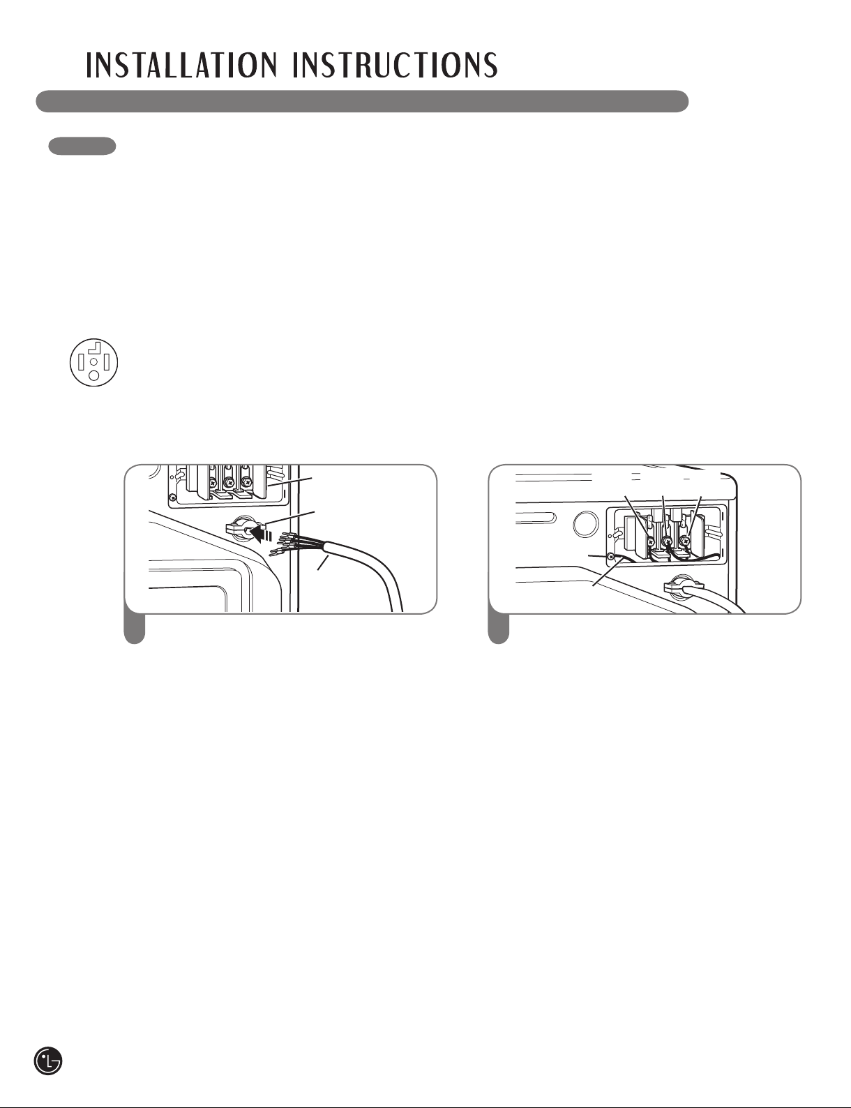
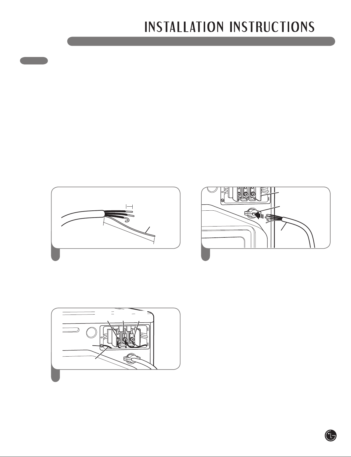
Four-Wire Connection for Electric Dryers: Power Cord
• A 4-wire connection is required for all mobile
and manufactured home installations, as well
as all new construction after January 1, 1996.
• A UL-listed strain relief is required.
Terminal
Block
UL-Listed
Strain Relief
UL-Listed
4-Wire
Power Cord
Remove the terminal block access cover
1
on the upper back of the dryer. Install a
UL-listed strain relief into the power cord
through-hole; then thread a UL-listed, 30A,
240V, 4-wire, #10 AWG-minimum copper
conductor power cord through the
strain relief.
• Use a 30-amp, 240V, UL-listed power cord
with #10 AWG-minimum copper conductor
and closed loop or forked terminals with
upturned ends.
Hot
(Black)
Ground Screw
Power Cord
Ground Wire
2
Transfer the dryer’s ground wire from behind
Neutral
(White)
Hot
(Red)
the green ground screw to the center screw
of the terminal block. Attach the two hot
leads of the power cord to the outer terminal
block screws. Attach the white neutral wire
to the center terminal block screw. Attach the
power cord ground wire to the green ground
screw. TIGHTEN ALL SCREWS SECURELY.
Reinstall the terminal block access cover.
18
Page 19
CONNECTING ELECTRIC DRYERS (cont.)
USA ONLY
wWARNING:
• Connect the power cord to the terminal block. Each colored wire should be connected
to same color screw. Wire color indicated on manual is connected to the same color
screw in block. Failure to follow these instructions may result in a short or overload.
Grounding through the neutral conductor is prohibited for: (1) new branch-circuit
•
installations, (2) mobile homes, (3) recreational vehicles, and (4) areas where local
codes prohibit grounding through the neutral conductor.
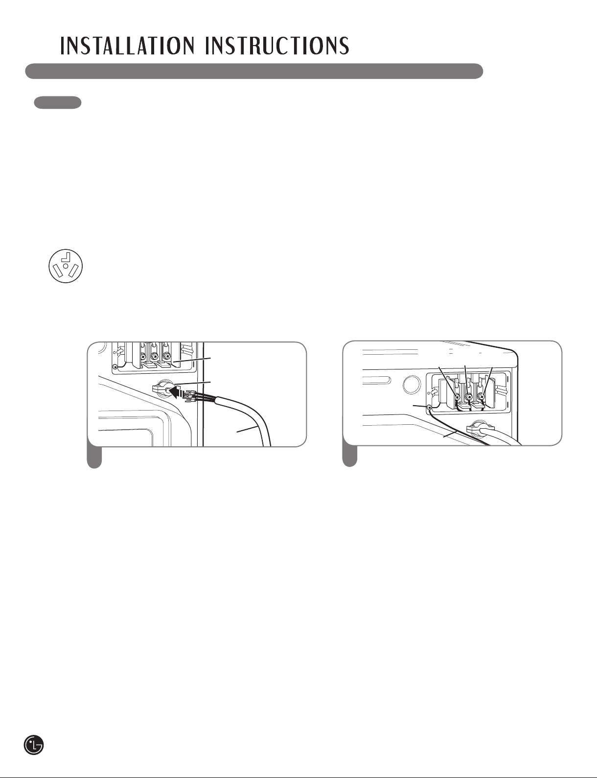
Four-Wire Connection for Electric Dryers: Direct Wire
• A 4-wire connection is required for all mobile
and manufactured home installations, as well
as all new construction after January 1, 1996.
• A UL-listed strain relief is required.
1" (2.5 cm)
Ground Wire
• Use UL-listed 4-wire #10 AWG-minimum
copper conductor cable.
• Allow at least 5 ft (1.5 m) length to allow for
removal and reinstallation of the dryer.
Terminal
Block
UL-Listed
Strain Relief
5"
(12.7 cm)
Remove 5 inches (12.7 cm) of the outer
1
covering from the wire. Remove 5 inches
of insulation from the ground wire. Cut off
approximately 11⁄2 inches (3.8 cm) from the
other three wires and strip 1 inch (2.5 cm)
insulation from each wire. Bend the ends of
the three shorter wires into a hook shape.
Hot
(Black)
Ground Screw
Ground Wire
3
Transfer the dryer’s ground wire from behind
Neutral
(White)
Hot
(Red)
the green ground screw to the center screw
of the terminal block. Attach the two hot
leads of the power cable to the outer terminal
block screws. Attach the white neutral wire
to the center terminal block screw. Attach the
power cable ground wire to the green ground
screw. TIGHTEN ALL SCREWS SECURELY.
Reinstall the terminal block access cover.
UL-Listed
4-Wire
Power Cord
Remove the terminal block access cover
2
on the upper back of the dryer. Install a
UL-listed strain relief into the power cord
through-hole; then thread the power cable
prepared in Step 1 through the strain relief.
19
Page 20
CONNECTING ELECTRIC DRYERS (cont.)
USA ONLY
wWARNING:
• Connect the power cord to the terminal block. Each colored wire should be connected
to same color screw. Wire color indicated on manual is connected to the same color
screw in block. Failure to follow these instructions may result in a short or overload.
• Grounding through the neutral conductor is prohibited for: (1) new branch-circuit
installations, (2) mobile homes, (3) recreational vehicles, and (4) areas where local
codes prohibit grounding through the neutral conductor.
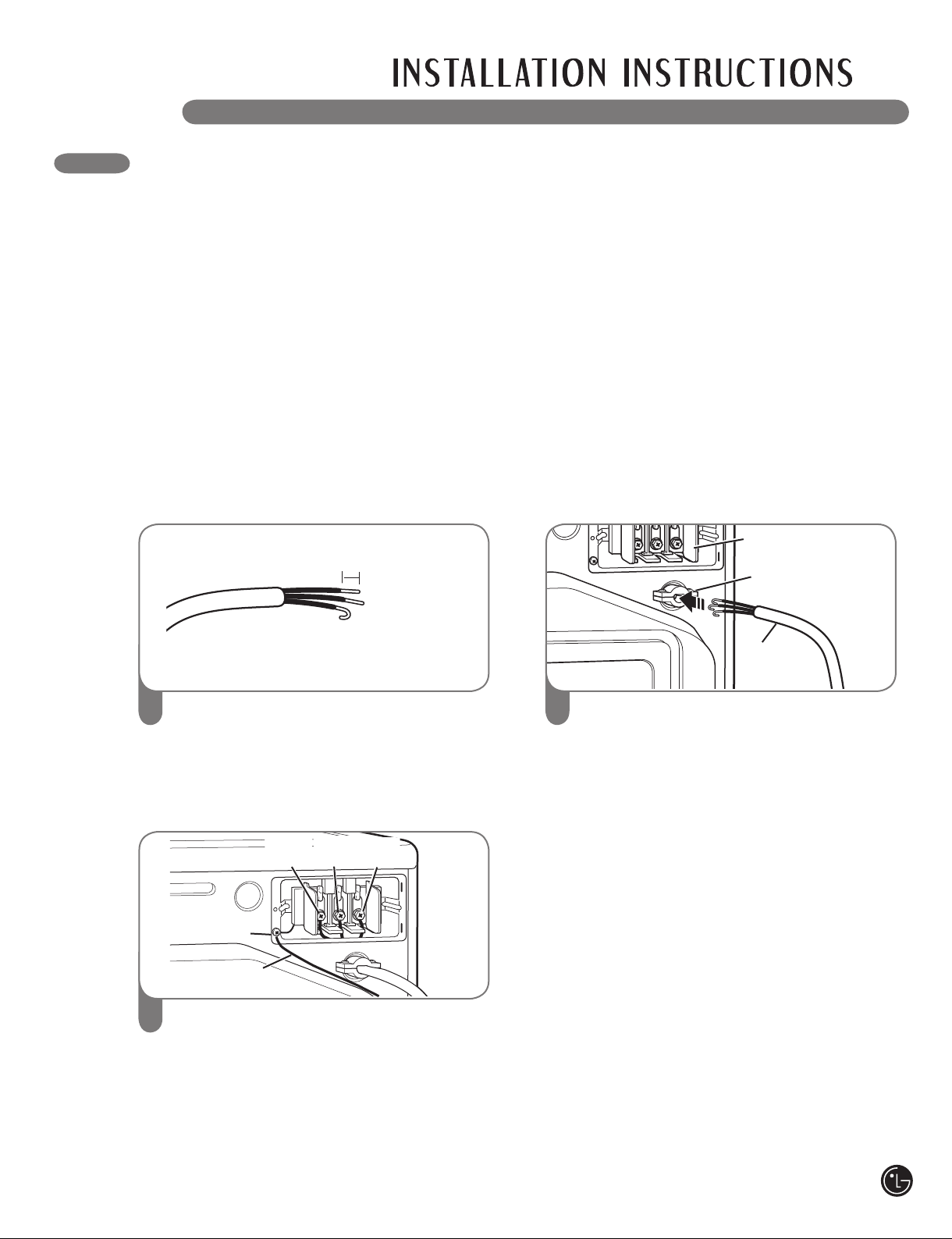
Three-Wire Connection for Electric Dryers: Power Cord
• A 3-wire connection is NOT permitted on new
construction after January 1, 1996.
• A UL-listed strain relief is required.
Terminal
Block
UL-Listed
Strain Relief
UL-Listed
3-Wire
Power Cord
Remove the terminal block access cover
1
on the upper back of the dryer. Install a
UL-listed strain relief into the power cord
through-hole; then thread a UL-listed, 30A,
240V, 3-wire, #10 AWG-minimum copper
conductor power cord through the strain
relief.
• Use a 30-amp, 240V, UL-listed power cord
with #10 AWG-minimum copper conductor
and closed loop or forked terminal s with
upturned ends.
Hot
(Black)
Ground Screw
Ground Wire
2
Attach the two hot leads of the power cord
Neutral
(White)
Hot
(Red)
to the outer terminal block screws. Attach
the neutral wire to the center terminal block
screw. Connect the external ground (if
required by local codes) to the green ground
screw. TIGHTEN ALL SCREWS SECURELY.
Reinstall the terminal block access cover.
20
Page 21
CONNECTING ELECTRIC DRYERS (cont.)
USA ONLY
wWARNING:
• Connect the power cord to the terminal block. Each colored wire should be connected
to same color screw. Wire color indicated on manual is connected to the same color
screw in block. Failure to follow these instructions may result in a short or overload.
Grounding through the neutral conductor is prohibited for: (1) new branch-circuit
•
installations, (2) mobile homes, (3) recreational vehicles, and (4) areas where local
codes prohibit grounding through the neutral conductor.
Three-Wire Connection for Electric Dryers: Direct Wire
• A 3-wire connection is NOT permitted on new
construction after January 1, 1996.
• A UL-listed strain relief is required.
1" (2.5 cm)
Remove 31⁄2 inches (8.9 cm) of the outer
1
covering from the wire. Strip 1 inch (2.5 cm)
insulation from each wire. Bend the ends of
the three wires into a hook shape.
Neutral
Hot
Black)
(White)
Hot
(Red)
• Use UL-listed 3-wire #10 AWG-minimum
copper conductor cable.
• Allow at least 5 ft (1.5 m) length to allow for
removal and reinstallation of the dryer.
Terminal
Block
UL-Listed
Strain Relief
UL-Listed
3-Wire
Power Cord
Remove the terminal block access cover
2
on the upper back of the dryer. Install a
UL-listed strain relief into the power cord
through-hole; then thread the power cable
prepared in Step 1 through the strain relief.
Ground Screw
Ground Wire
3
Attach the two hot leads of the power cord
to the outer terminal block screws. Attach
the neutral wire to the center terminal block
screw. Connect the external ground (if
required by local codes) to the green ground
screw. TIGHTEN ALL SCREWS SECURELY.
Reinstall the terminal block access cover.
21
Page 22
SPECIAL REQUIREMENTS FOR MANUFACTURED OR MOBILE HOMES
Any installation in a manufactured or mobile
home must comply with the Manufactured Home
Construction and Safety Standards Title 24 CFR,
Part 32-80 or Standard CAN/CSA0Z240 MH and
local codes and ordinances. If you are uncertain
whether your proposed installation will comply
with these standards, please contact a service
and installation professional for assistance.
• A gas dryer must be permanently attached to
the fl oor.
• The electrical connection for an electric dryer
must be a 4-wire connection. More detailed
information concerning the electrical connection
is provided in the section Connecting Electric
Dryers.
• To reduce the risk of combustion and fi re, the
dryer must be vented to the outside.
• DO NOT vent the dryer under a manufactured
home or mobile home.
• Electric dryers may be vented to the outside
using the back, left, right, or bottom panel.
• Gas dryers may be vented to the outside using
the back, left, or bottom panel. Gas dryers may
not be vented to the outside using the right side
panel because of the burner housing.
• The dryer exhaust duct must be affi xed securely
to the manufactured or mobile home structure,
and the exhaust duct must be made of a
material that will resist fi re and combustion.
It is recommended that you use a rigid or
fl exible metal duct.
• DO NOT connect the dryer exhaust duct
to any other duct, vent, chimney, or other
exhaust duct.
• Make sure the dryer has adequate access to
outside fresh air to ensure proper operation.
The opening for outside fresh air must be at
least 25 in2 (163 cm2).
• It is important that the clearance of the duct
from any combustible construction be at least
2 in. (5 cm), and when venting the dryer to
the outdoors, the dryer can be installed with a
clearance of 1 in. (2.5 cm) at the sides and back
of the dryer.
• Please be aware that venting materials are
not supplied with the dryer. You should obtain
the venting materials necessary for proper
installation.
FINAL INSTALLATION CHECK
Once you have completed the installation of
the dryer and it is in its final location, confirm
proper operation with the following tests.
Testing Dryer Heating
GAS MODELS
Close the dryer door, press the ON/OFF switch
to turn the dryer on, and start the dryer on a heat
setting. When the dryer starts, the igniter should
ignite the main burner.
NOTE: If all air is not purged from the gas line,
the gas igniter may turn off before the main
burner ignites. If this happens, the igniter will
reattempt gas ignition after approximately
two minutes.
ELECTRIC MODELS
Close the dryer door, press the ON/OFF switch
to turn the dryer on, and start the dryer on a heat
setting. The exhaust air should be warm after the
dryer has been operating for 3 minutes.
Checking Airflow
Effective dryer operation requires proper airflow.
The adequacy of the airflow can be measured
by evaluating the static pressure. Static pressure
in the exhaust duct can be measured with
a manometer, placed on the exhaust duct
approximately 2 ft. (60.9 cm) from the dryer.
Static pressure in the exhaust duct should not
exceed 0.6 in. (1.5 cm). The dryer should be
checked while the dryer is running with no load.
Checking Levelness
Once the dryer is in its final location, recheck
the dryer to be sure it is level. Make sure it is
level front to back and side to side, and that
all 4 leveling feet are firmly on the floor.
22
Page 23
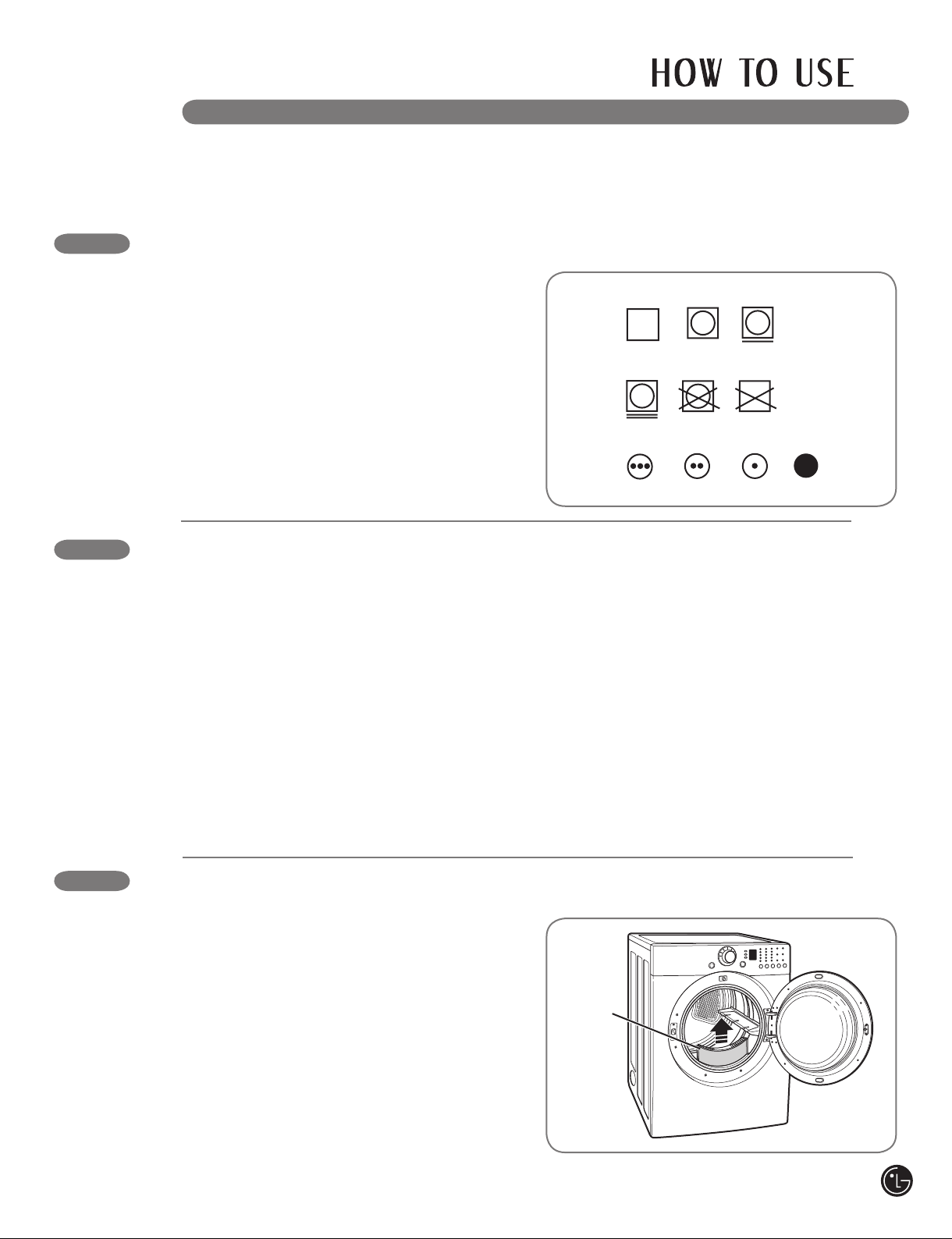
Tumble
dry
Dry
Normal
Permanent Press
/
wrinkle resistant
Gentle/
delicate
Do not tumble dry
Do not dry
(used with
do not wash)
Heat
setting
High
Medium
Low
No heat/air
Following are instructions for starting and using your new dryer. Please refer to specific sections of this
manual for more detailed information. Important Warning: To reduce the risk of fire, electric shock,
or injury to persons, read this entire manual, including the Important Safety Instructions, before
operating this dryer.
SORTING LOADS
Fabric Care Labels
Fabric Care Labels
Most articles of clothing feature fabric care labels
that include instructions for proper care.
Grouping Similar Items
For best results, sort clothes into loads that can
be dried with the same drying cycle.
Different fabrics have different care
requirements, and some fabrics will dry
more quickly than others.
LOADING THE DRYER
wWARNING: To reduce the risk of fire, electric shock, or injury to persons when using this
appliance, follow basic precautions, including the following:
• Check all pockets to make sure that they are
empty. Items such as clips, pens, coins, and
keys can damage both your dryer and your
clothes. Flammable objects such as lighters
or matches could ignite, causing a fire.
Failure to do so can result in fire, explosion,
or death.
• Never dry clothes that have been exposed to
oil, gasoline, or other flammable substances.
Washing clothes will not completely remove
oil residues. Failure to obey this warning can
result in fire, explosion, or death.
• Combine large and small items in a load.
• Damp clothes will expand as they dry. Do not
overload the dryer; clothes require room to
tumble dry properly.
• Close zippers, hooks, and drawstrings to
prevent these items from snagging or tangling
on other clothes.
CHECK THE LINT FILTER BEFORE EVERY LOAD
Always make sure the lint filter is clean before
starting a new load; a clogged lint filter will
increase drying times.
To clean, pull the lint filter straight up and roll any
lint off the filter with your fingers. Do not rinse or
wash the filter to remove lint. Push the lint filter
firmly back into place. See “Care and Cleaning”
for more information.
Always ensure the lint filter is properly installed
before running the dryer. Running the dryer with
a loose or missing lint filter may damage the
dryer and articles in the dryer.
Lint Filter
23
Page 24
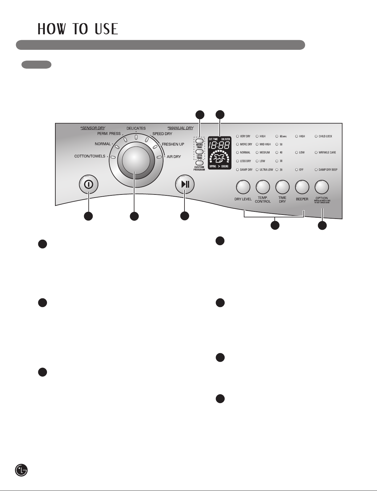
CONTROL PANEL FEATURES
Following are instructions for starting and using your new dryer. Please refer to specific sections of this
manual for more detailed information. Important Warning: To reduce the risk of fire, electric shock,
or injury to persons, read this entire manual, including the Important Safety Instructions, before
operating this dryer.
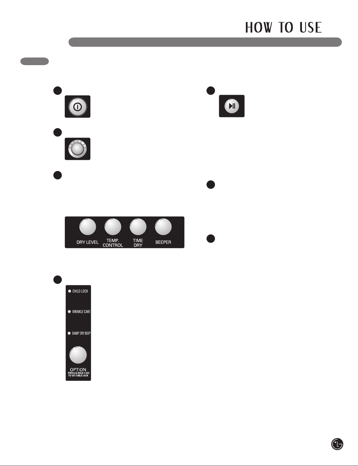
1
1
POWER ON/OFF BUTTON
Press to turn the dryer ON. Press again to
turn the dryer OFF.
NOTE: Pressing the ON/OFF button during
a cycle will cancel that cycle and any load
settings will be lost.
2
4
3
6
5
4
MORE TIME/LESS TIME BUTTONS
Use these buttons with MANUAL DRY and
TIME DRY cycles to adjust the drying time.
Press the MORE TIME button to increase
the selected manual cycle time by a minute;
press LESS TIME to decrease the cycle time
by a minute.
7
24
2
CYCLE SELECTOR KNOB
Turn this knob to select the desired cycle.
Once the desired cycle has been selected,
the standard presets will be shown in the
display. On MANUAL DRY cycles, these
settings can be adjusted using the cycle
settings buttons anytime before starting
the cycle.
3
START/PAUSE BUTTON
Press this button to START the selected
cycle. If the dryer is running, use this button
to PAUSE the cycle without losing the
current settings.
NOTE: If you do not press the START/PAUSE
button to resume a cycle within 4 minutes,
the dryer automatically turns off.
5
CYCLE SETTINGS BUTTONS
Use these buttons to select the desired cycle
settings for the selected cycle. The current
settings are shown in the display. Press the
button for that option to view and select
other settings.
6
LED DISPLAY
The display shows the settings, estimated
time remaining, options, and status
messages for your dryer.
7
OPTION BUTTON
The option buttons allow you to select
additional cycle options.
For detailed information about the individual
options, please see the following pages.
Page 25
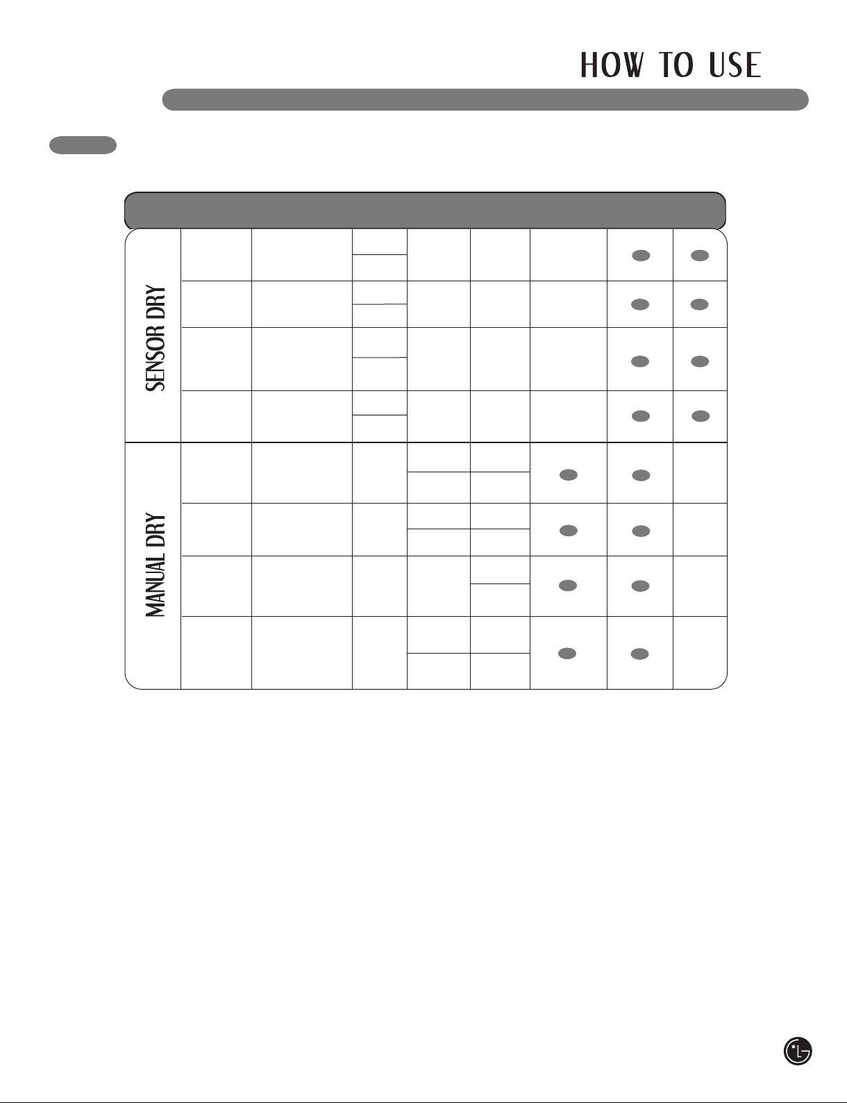
CYCLE GUIDE
The cycle guide below shows the options and recommended fabric types for each cycle.
Type
Cycle
COTTON/
TOWELS
NORMAL
PERM. PRESS
DELICATES
SPEED DRY
FRESHEN UP
AIR DRY
Fabric Type
Denims, towels,
heavy cottons
Work clothes,
corduroys, etc.
Permanent press,
synthetic items
Lingerie, sheets,
blouses
For small loads
with short
drying times
For removing
light wrinkles
from clothing
For irems that
require heat-free
drying such as
plastics or rubber
Dry
Level
Normal
Adjustable
Normal
Adjustable
Normal
Adjustable
Normal
Adjustable
off
off
off
Temperature
MID HIGH
MEDIUM
LOW
LOW
HIGH
Adjustable
MID HIGH
Adjustable
No Heat
Time
in Min.
55
41
36
32
25
Adjustable
20
Adjustable
30
Adjustable
More Time/
Less Time
Wrinkle
Care
Damp
Dry
For general drying;
TIME DRY
time, temperature,
and options can be
set manually
off
Sensor Dry Cycles
Sensor Dry cycles utilize LG’s unique dual sensor
system to detect and compare the moisture level
in clothes and in the air and adjust the drying
time as needed to ensure superior results. The
dryer automatically sets the dryness level and
temperature at the recommended setting for
each cycle. The estimated time remaining will
HIGH
Adjustable
40
Adjustable
Manual Dry Cycles
Use Manual Dry cycles to select a specific
amount of drying time and a drying temperature.
When a Manual Dry cycle is selected, the
ESTIMATED TIME REMAINING display shows
the actual time remaining in your cycle. You can
change the actual time in the cycle by pressing
MORE TIME or LESS TIME.
be shown in the display.
NOTE: To protect your garments, not every dry level, temperature, or option is available
with every cycle.
25
Page 26
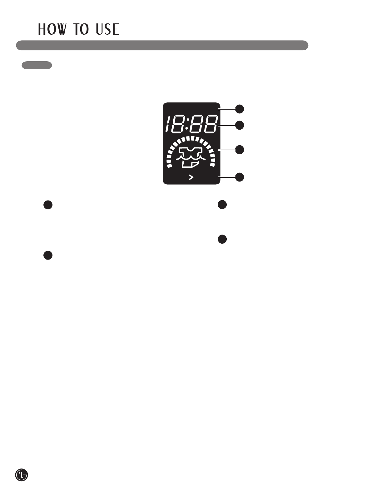
THE LED DISPLAY
DRYING
EST. TIME
CHK. FILTER
COOLING
The LED display shows the settings, estimated time remaining, options, and status messages
for your dryer. When the dryer is turned on, the light in the display will illuminate.
1
2
3
4
1
CHECK FILTER REMINDER
The display will show CHK.FILTER when the
dryer is turned on as a reminder to check
the filter. It turns off when the START/PAUSE
button is pressed.
ESTIMATED TIME REMAINING
2
When the START/PAUSE button is pressed,
the dryer will display the estimated (SENSOR
DRY) or set time (TIME DRY) remaining, and
begin tumbling.
NOTE: The cycle time on SENSOR
DRY cycles may fluctuate as the dryer
recalculates drying time for optimal results.
3
CYCLE COMPLETION INDICATOR
Shows how much of the current
drying cycle has been completed.
4
STATUS/CYCLE DISPLAY
This portion of the display shows the
selected cycle, operating status, and special
messages. If a cycle has special instructions,
they will also be displayed in this area.
26
Page 27
OPERATING THE DRYER
Once you have loaded the dryer:
Press the ON/OFF button to turn on the
1
dryer. The lights around the cycle
selector knob will illuminate.
Turn the cycle selector knob to the desired
2
cycle. The display will show
the preset Dry Level,
Temperature, Time, and
Option settings for that cycle.
3
If you would like to change the settings
for that cycle, press the option button(s)
to display additional settings for that option.
Press the button again to cycle through
the settings until the desired setting is
highlighted.
NOTE: To protect your garments, not every
dry level, temperature, or option is available
with every cycle.
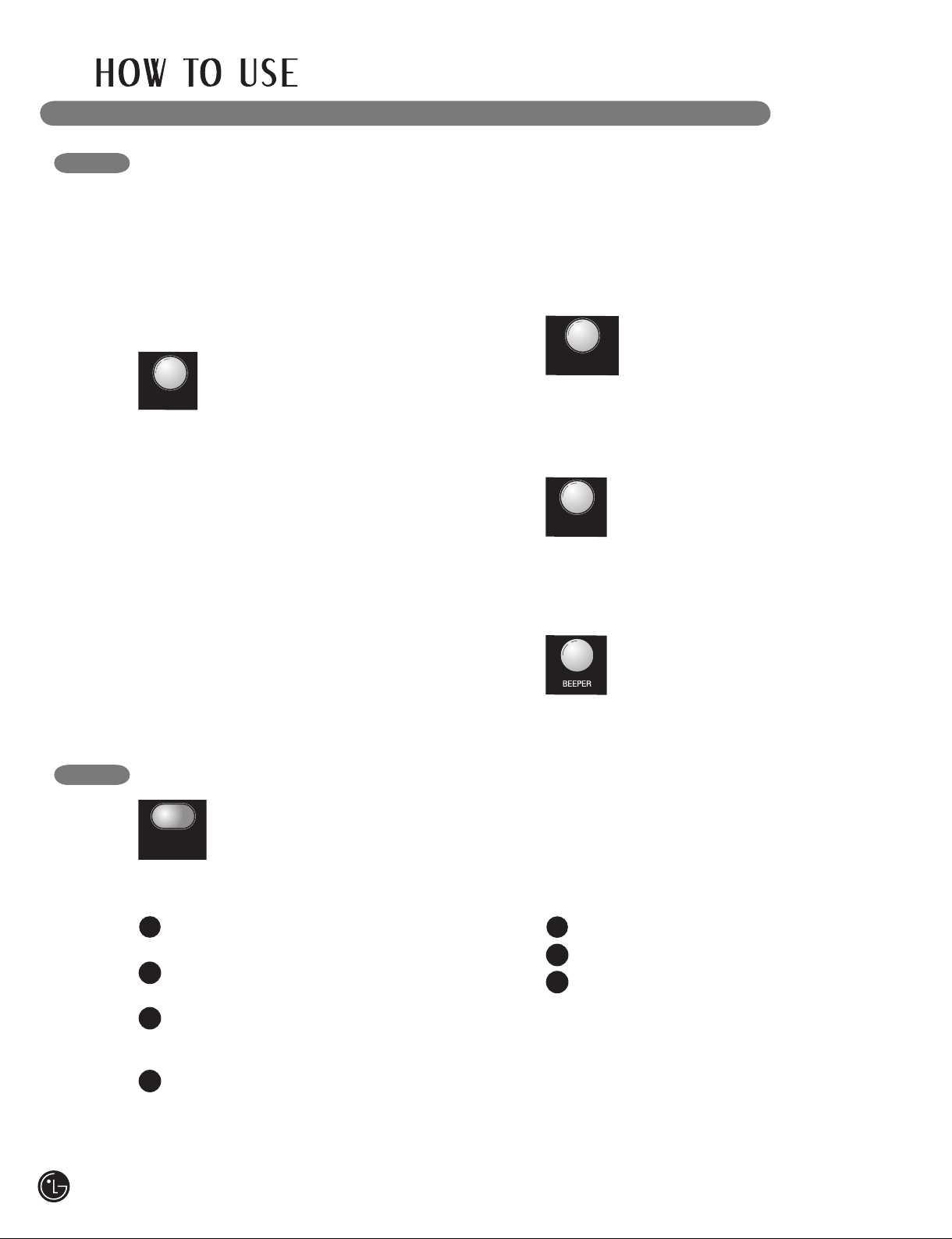
Press the START/PAUSE button to begin the
5
cycle. The display will change,
and the dryer will display the
estimated (SENSOR DRY) or set
time (MANUAL DRY) remaining
and start tumbling. To pause the cycle at any
time, open the dryer door or press PAUSE.
To resume the cycle where it was stopped,
press START/PAUSE again.
NOTE: If the dryer has been stopped for
more than 8 minutes, the dryer will turn
off automatically.
When the load is finished, the beeper (if
6
set) will sound. If you have set the Wrinkle
Care option, the dryer will tumble the load
periodically for up to 3 hours.
To prevent wrinkling, remove items from the
dryer immediately after the end of the cycle.
Always clean the lint filter after every cycle.
7
To clean, pull the lint filter straight up and
roll any lint off the filter with your fingers.
Do not rinse or wash the filter to remove lint.
Push the lint filter firmly back into place.
Select any additional cycle options, such
4
as CHILD LOCK, WRINKLE
CARE, or DAMP DRY BEEP,
by pressing the button
for that option.
NOTE: To protect your garments,
not every dry level, temperature,
or option is available with every
cycle.
27
Page 28
CYCLE SETTING BUTTONS
DRY LEVEL
CUSTOM
PROGRAM
TEMP.
CONTROL
TIME
DRY
SENSOR DRY cycles have preset settings
that are selected automatically and cannot be
changed. MANUAL DRY cycles have default
settings, but you may also customize the settings
using the cycle setting buttons. Press the button
for that option to view and select other settings.
DRY LEVEL
Selects the level of dryness for the
cycle. Press the DRY LEVEL button
repeatedly to scroll through available
settings.
• This option is only available with SENSOR DRY
cycles.
• The dryer will automatically adjust the cycle
time. Selecting VERY DRY or MORE DRY will
increase the cycle time, while LESS DRY or
DAMP DRY will decrease the cycle time.
• Use a LESS DRY or DAMP DRY setting for
items that you wish to iron.
NOTE: To protect your garments, not every
dryness level, temperature, or option is available
with every cycle. See the Cycle Guide for details.
TEMP. CONTROL
Adjusts the temperature setting from
ULTRA LOW to HIGH. This allows
precise care of your fabrics
and garments. Press the TEMP.
CONTROL button repeatedly to scroll through
available settings.
TIME DRY
Allows you to manually select the drying
time, from 20 to 60 minutes, in 10minute increments. Use this for small
loads or to remove wrinkles. Use the
MORE TIME/LESS TIME buttons to add or reduce
the drying time in 1-minute increments.
BEEPER
Adjusts the volume of the end-of-cycle
beeper, or turns off the beeper.
28
CUSTOM PROGRAM
If you have a special combination of
settings that you use frequently, you
can save these settings as a CUSTOM
PROGRAM.
To Save a Custom Program:
Turn on the dryer and turn the cycle selector
1
knob to select the desired cycle.
Use the cycle setting buttons to adjust the
2
settings for that cycle.
Press the cycle option button(s) for the
3
option you would like to add. A confirmation
message will be shown in the display.
Press and hold the CUSTOM PROGRAM
4
button for 3 seconds.
NOTE: You may only save one custom
program at a time. Pressing and holding the
CUSTOM PROGRAM button will overwrite
any previously saved custom program.
To Recall a Custom Program:
Turn on the dryer.
1
Press the CUSTOM PROGRAM button.
2
Press the START/PAUSE button to start
3
the cycle.
Page 29
CYCLE OPTION BUTTONS
Your dryer features several additional cycle
options to customize cycles to meet your
individual needs. Certain option buttons also
feature a special function (see the following page
for details) that can be activated by pressing and
holding that option button for 3 seconds.
To Add Cycle Options to a Cycle:
Turn on the dryer and turn the cycle selector
1
knob to select the desired cycle.
Use the cycle settings buttons to adjust the
2
settings for that cycle.
Press the cycle option button(s) for the
3
option you would like to add. A confirmation
message will be shown in the display.
Press the START/PAUSE button to start the
4
cycle. The dryer will start automatically.
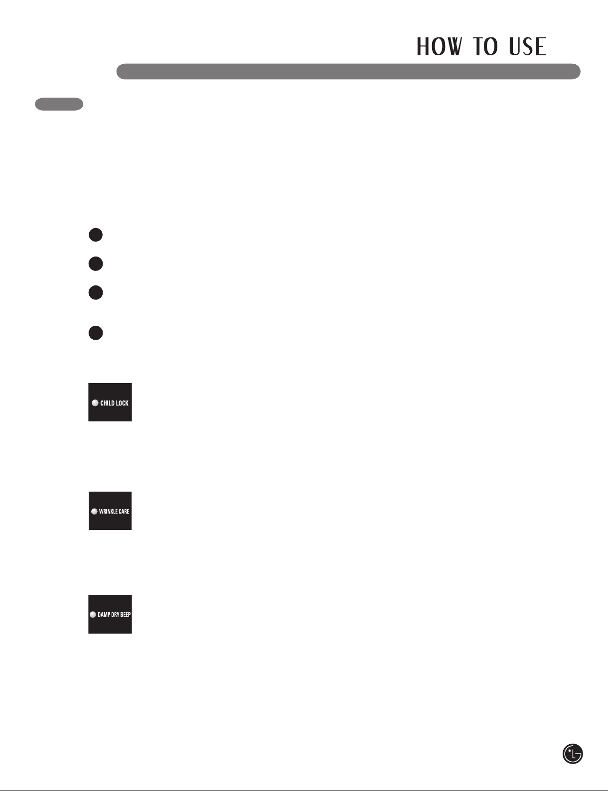
CHILD LOCK
Use this option to prevent unwanted
use of the dryer or to keep cycle
settings from being changed while the
dryer is operating.
All controls are disabled. The dryer can be locked
during a cycle.
WRINKLE CARE
Selecting this option will tumble the
load periodically for up to 3 hours after
the selected cycle, or until the door is
opened. This is helpful in preventing
wrinkles when you are unable to immediately
remove items from the dryer.
DAMP DRY BEEP
With this option, the dryer will beep
when the load is approximately 80%
dry. This allows you to remove faster-
drying lightweight items or items
that you would like to iron or hang while still
slightly damp.
29
Page 30
REGULAR CLEANING
wWARNING: To reduce the risk of fire, electric shock, or injury to persons when using this
appliance, follow basic precautions, including the following:
• Unplug the dryer before cleaning to avoid the risk of electric shock. Failure to follow this warning can
cause serious injury, fi re, electrical shock, or death.
• Never use harsh chemicals, abrasive cleaners, or solvents to clean the washer.
They will damage the finish.
Cleaning the Exterior
Proper care of your dryer can extend its life.
The outside of the machine can be cleaned with
warm water and a mild, nonabrasive household
detergent.
Immediately wipe off any spills with a soft,
damp cloth.
IMPORTANT: Do not use methylated spirits,
solvents, or similar products.
Never use steel wool or abrasive cleansers; they
can damage the surface.
Cleaning the Interior
Wipe around the door opening and seal with a
soft, damp cloth to prevent lint and dust buildup
that could damage the door seal.
Clean the window with a soft cloth dampened
with warm water and a mild, nonabrasive
household detergent; then wipe dry.
The stainless steel drum can be cleaned with
a conventional stainless steel cleaner, used
according to the manufacturer’s specifications.
Never use steel wool or abrasive cleansers; they
can scratch or damage the surface.
Cleaning Around and Under the Dryer
Vacuum lint and dust from around the dryer and
underneath it regularly. Vent ductwork should be
checked for lint buildup and cleaned at least once
per year. If any noticeable reduction in airflow or
drying performance occurs, immediately check
ductwork for obstructions and blockages.
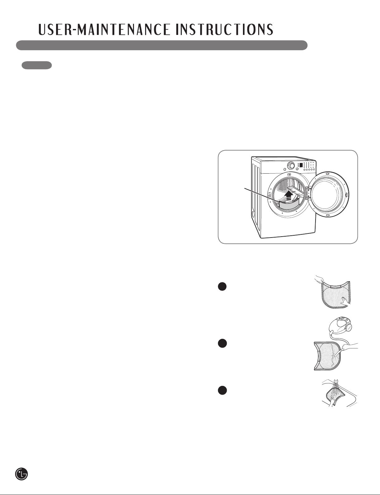
Cleaning the Lint Filter
Lint Filter
Always clean the lint filter after every cycle.
To clean, open the dryer door and pull the lint
filter straight up. Then:
1
Roll any lint off the filter with
your fingers, or
2
Vacuum the lint filter, or
3
Wash the lint filter in warm,
soapy water and allow to dry
thoroughly before reinstalling.
30
Maintaining Ductwork
Vent ductwork should be checked for lint
buildup and cleaned at least once per year. If
any noticeable reduction in airflow or drying
performance occurs, immediately check ductwork
for obstructions and blockages. Contact a
qualified technician or service provider.
NOTE: NEVER operate the dryer without the lint
filter in place.
Page 31

BEFORE CALLING FOR SERVICE
Your dryer is equipped with an automatic error-monitoring system to detect and diagnose problems at an
early stage. If your dryer does not function properly or does not function at all, check the following before
you call for service.
Problem Possible Causes Solutions
Dryer will not
turn on
Dryer does not heat
Greasy or dirty spots
on clothes
Display shows error
code tE1 or tE2
Lint on clothes
• Power cord is not properly
plugged in.
• House fuse is blown, circuit
breaker has tripped, or
power outage has occurred.
• House fuse is blown, circuit
breaker has tripped, or
power outage has occurred.
• Gas supply or service turned
off (gas models only).
• Fabric softener used
incorrectly.
• Clean and dirty clothes being
dried together.
• Clean and dirty clothes being
dried together.
• Thermistor is malfunctioning.
• Lint filter not cleaned
properly.
• Laundry not sorted properly.
• Excess static in clothes.
• Dryer is overloaded.
• Tissue, paper, etc., left
in pockets.
• Make sure that the plug is plugged securely into a
grounded outlet matching the dryer’s rating plate.
• Reset circuit breaker or replace fuse. Do not increase
fuse capacity. If the problem is a circuit overload,
have it corrected by a qualified electrician.
• Reset circuit breaker or replace fuse. Do not
increase fuse capacity. If the problem is a
circuit overload, have it corrected by a qualified
electrician.
• Confirm that the house gas shutoff and the dryer
gas shutoff are both fully open.
• Confirm and follow the instructions provided with
your fabric softener.
• Make sure to use your dryer to dry only clean
items, because dirty items can soil clean clothes
placed in the same or subsequent loads.
• Stains on dried clothes are actually stains that
weren’t removed during the washing process.
Make sure that clothes are being completely
cleaned according to the instructions for your
washer and detergent.
• Turn off the dryer and call for service.
• Make sure the lint filter is cleaned before every
load. With some loads that produce high amounts
of lint, it may be necessary to clean the filter
during the cycle.
• Some fabrics are lint producers (i.e., a fuzzy white
cotton towel) and should be dried separately from
clothes that are lint trappers (i.e., a pair of black
linen pants).
• See the
section below.
• Divide larger loads into smaller loads for drying.
• Check pockets thoroughly before washing and
drying clothes.
Excess static in clothes after drying
Excess static in
clothes after drying
• Fabric softener not used or
used incorrectly.
• Clothes dried too long
(overdried).
• Drying synthetics, permanent
press, or synthetic blends.
• Use a fabric softener to reduce static electricity.
Be sure to follow the manufacturer’s instructions.
• Overdrying a load of laundry can cause a buildup
of static electricity. Adjust settings and use a
shorter drying time, or use SENSOR DRY cycles.
• These materials can cause static buildup. Try
using a fabric softener.
31
Page 32

BEFORE CALLING FOR SERVICE (cont.)
Problem Possible Causes Solutions
Drying time is not
consistent
Clothes take too
long to dry
• Heat settings, load size, or
dampness of clothing is not
consistent.
• Load is not properly sorted.
• Large load of heavy fabrics.
• Dryer controls are not set
properly.
• Lint fi lter needs to be
cleaned.
• Exhaust ducts blocked, dirty,
or duct run is too long.
• House fuse is blown, circuit
breaker has tripped, or
power outage has occurred.
• Dryer is overloaded.
• Dryer is underloaded.
• The drying time for a load will vary depending on the
heat setting, the type of heat used (electric, natural,
or LP gas), the size of the load, the type of fabrics,
the wetness of the clothes, and the condition of the
exhaust ducts and lint fi lter.
• Separate heavy items from lightweight items. Larger
and heavier items take longer to dry.
• Heavy fabrics take longer to dry because they tend
to retain more moisture. To help reduce and maintain
more consistent drying times for large and heavy
fabrics, separate these items into smaller loads of
a consistent size.
• Use the appropriate control settings for the type of
load you are drying.
• Make sure the lint fi lter is cleaned before every load.
With some loads that produce high amounts of lint, it
may be necessary to clean the fi lter during the cycle.
• Confi rm that the exhaust ductwork is properly
confi gured and free of debris, lint, and obstructions.
Make sure that outside wall dampers can open
properly and are not blocked, jammed, or damaged.
• Reset circuit breaker or replace fuse. Do not
increase fuse capacity. If the problem is a circuit
overload, have it corrected by a qualifi ed electrician.
• Divide larger loads into smaller loads for drying.
• If you are drying a very small load, add a few extra
items to ensure proper tumbling action.
32
Clothes are wrinkled
Clothes are shrinking
• Clothes dried too long
(overdried).
• Clothes left in dryer too long
after cycle ends.
• Garment care instructions
are not being followed.
• Overdrying a load of laundry can lead to wrinkled
clothes. Try a shorter drying time, and remove items
while they still retain a slight amount of moisture.
• Remove items from the dryer immediately at the
end of the cycle. Use the WRINKLE CARE option to
continue tumbling clothes at the end of the cycle, for
up to 3 hours.
• To avoid shrinkage, please carefully follow the fabric
care instructions for your garment, because some
fabrics will naturally shrink when washed. Other
fabrics can be washed but will shrink when dried
in a dryer. Use a low or no heat setting and/or the
RACK DRY option.
Page 33

KEY DIMENSIONS AND SPECIFICATIONS
The appearance and specifications listed in this guide may vary due to constant product improvements.
Dryer Models DLE2101W DLG2102W, DLE2101R, DLG2102R, DLE2101S, DLG2102S,
DLE2101L and DLG2102L
Description Dryer
Electrical Requirements* Please refer to the rating label regarding detailed information.
Gas Requirements* NG: 10–13 in. WC/LP: 10–13 in. WC (Gas Models only)
Dimensions 27"(W) X 30"(D) X 3811/16"(H), 50" (D with door open)
68.6 cm (W) X 76.1 cm (D) X 98.3 cm (H),127 cm (D with door open)
Net Weight 126 lb. (57.2 kg)
Drying Capacity IEC 7.3 cu.ft. (22.5 lbs./10.2 kg)
*Refer to the rating plate on your dryer.
OPTIONAL ACCESSORIES
For these and other LG products, contact your local LG dealer, or visit our Web site at ca.lge.com
Pedestal
Give your LG washer
and dryer a boost with
matching 14-inch high
pedestals. They feature
a storage drawer for
added convenience.
14" Pedestal Color
WDP3W White
WDP3B Black
WDP3S Titanium
WDP3N Navy Blue
WDP3R Wild Cherry Red
Stacking Kit
If space is at a premium,
use this kit to securely
stack your LG front-load
washer and dryer.
Bracket Kit Color
WSTK1 White
BSTK1 Black
SSTK1 Titanium
NSTK1 Navy Blue
RSTK1 Wild Cherry Red
33
Page 34

PEDESTAL INSTALLATION
The pedestal accessory includes:
• Drawer divider (1) • Wrench (1)
• Screws (18) † • Retainers (4) ††
† Dryer installation only uses 8 screws
†† For dryer only
Tools Needed for Installation:
• Phillips-head screwdriver
• Wrench (supplied)
To ensure safe and secure installation, please
thoroughly follow the instructions below.
wWARNING
• Incorrect installation can cause serious
accidents.
• The appliances are heavy. Two or more
people are required when installing the
pedestal. There is a risk of serious back injury
or other injuries.
• Do not allow children to play in or on the
drawer. There is a risk of suffocation or injury.
• Do not step on the handle. There is a risk of
serious injury.
• If appliances are already installed,
disconnect them from all power, water, or
gas lines and from draining or venting
connections. Failure to do so can result in
electrical shock, fire, explosion, or death.
• When installing, gloves must be put on.
34
Retract fully
To set the dryer to the same height as the
1
washer, fully retract the leveling feet of the
dryer by turning them counterclockwise, then
turn them clockwise 1-1/2 turns.
NOTE: The appliance and pedestal assembly
must be placed on a solid, sturdy, level floor
for proper operation.
Then loosen
1-1/2 turns
T-clip
Retainer
Insert the T-clip of the 4 retainers into the
2
dryer base as shown. Press up on the
back of the clip and pull outward to lock
into place.
Page 35

PEDESTAL INSTALLATION (cont.)
For dryer
For washer/combo
Place the dryer on the pedestal. Make sure
3
the front and back feet are in the correct
positions. The dryer feet will fi t into the
innermost positions as shown.
Raise
Lower
Make sure the screws on the pedestal align
4
with the holes in the retainers, then install 4
screws at each corner to securely attach the
appliance to the pedestal.
NOTE: If the screws are not installed
properly, noise and vibration may result.
Move the appliance to the desired location.
Locknut
Loosen the locknuts on all 4 leveling feet
of the pedestal until you can turn them
with the wrench. Turn clockwise to raise or
counterclockwise to lower until the pedestal
is level and all 4 feet are solidly against the
floor.
Securely tighten all locknuts by hand.
65
NOTE: Noise and vibration may result if
locknuts are not tightened.
Be sure to connect the appliances to all
water, power, or gas lines and draining or
venting connections before operation.
If there is excessive vibration during the
first operation after installation, slightly
adjust the leveling feet.
35
Page 36

STACKING KIT INSTALLATION
This stacking kit includes:
• Two (2) side rails
• One (1) front rail
• Four (4) screws
Tools Needed for Installation:
• Phillips-head screwdriver
To ensure safe and secure installation, please
observe the following instructions.
wWARNING
• Incorrect installation can cause serious
accidents.
• The weight of the dryer and the height of
installation make this stacking procedure too
risky for one person. Two or more people are
required when installing the stacking kit.
There is a risk of serious back injury or other
injuries.
• Do not use the stacking kit with a gas dryer
in potentially unstable conditions such as a
mobile home. Failure to follow this warning can
result in serious injury.
• Place the washer on a solid, stable, level
fl oor capable of supporting the weight of
both appliances. Failure to follow this warning
can result in serious injury.
• If appliances are already installed,
disconnect them from all power, water,
or gas lines and from draining or venting
connections. Failure to do so can result
in electrical shock, fire, explosion, or death.
36
Make sure the surface of the washer is clean
1
and dry. Remove paper backing from the
tape on one of the stacking kit side brackets.
Fit the side bracket to the side of the washer
2
top as shown in the above illustration. Firmly
press the adhesive area of the bracket to the
washer surface. Secure the side bracket to
the washer with a screw on the back side of
the bracket. Repeat steps 1 and 2 to attach
the other side bracket.
Page 37

STACKING KIT INSTALLATION (cont.)
Dryer
Washer
Place the dryer on top of the washer by
3
fitting the dryer feet into the side brackets as
illustrated. Avoid finger injuries; do not allow
fingers to be pinched between the washer
and dryer. Slowly slide the dryer toward the
back of the washer until the side bracket
stoppers catch the dryer feet.
Insert the front rail between the bottom of
4
the dryer and the top of the washer. Push the
front rail toward the back of the washer until it
comes in contact with the side rail stoppers.
Install the two remaining screws to secure the
front rail to the side rails.
37
Page 38

LG ELECTRONICS, INC.
LG DRYER LIMITED WARRANTY - USA
Your LG Dryer will be will repaired or replaced, at LG’s option, if it proves to be defective in material or workmanship under
normal use, during the warranty period (“Warranty Period”) set forth below, effective from the date (“Date of Purchase”) of
original consumer purchase of the product. This warranty is good only to the original purchaser of the product and
effective only when used in the United States, including Alaska, Hawaii, and U.S. Territories.
WARRANTY PERIOD:
LABOR: One Year from the Date of Purchase.
PARTS: One Year from the Date of Purchase.
Replacement Units and Repair Parts may be new or
remanufactured.
Replacement Units and Repair Parts are warranted for the
remaining portion of the original unit’s warranty period.
HOW SERVICE IS HANDLED:
In-Home Service:
Please retain dealer’s dated bill of sale or delivery
ticket as evidence of the Date of Purchase for proof of
warranty, and submit a copy of the bill of sale to the
service person at the time warranty service is provided.
Please call 1-800-243-0000 and choose the
appropriate option to locate your nearest LG
Authorized Service Center.
Or visit our Web site at: http://www.lgservice.com.
THIS WARRANTY IS IN LIEU OF ANY OTHER WARRANTY, EXPRESS OR IMPLIED, INCLUDING WITHOUT LIMITATION,
ANY WARRANTY OF MERCHANTABILITY OR FITNESS FOR A PARTICULAR PURPOSE. TO THE EXTENT ANY IMPLIED
WARRANTY IS REQUIRED BY LAW, IT IS LIMITED IN DURATION TO THE EXPRESS WARRANTY PERIOD ABOVE.
NEITHER THE MANUFACTURER NOR ITS U.S. DISTRIBUTOR SHALL BE LIABLE FOR ANY INCIDENTAL, CONSEQUENTIAL,
INDIRECT, SPECIAL, OR PUNITIVE DAMAGES OF ANY NATURE, INCLUDING WITHOUT LIMITATION, LOST REVENUES OR
PROFITS, OR ANY OTHER DAMAGE WHETHER BASED IN CONTRACT, TORT, OR OTHERWISE. Some states do not allow
the exclusion or limitation of incidental or consequential damages or limitations on how long an implied warranty lasts, so the above
exclusion or limitation may not apply to you. This warranty gives you specifi c legal rights and you may also have other rights that vary
from state to state.
THIS LIMITED WARRANTY DOES NOT APPLY TO:
• Service trips to your home to deliver, pick up, and/or install the product, instruct, or replace house fuses or correct wiring, or
correction of unauthorized repairs.
• Damages or operating problems that result from misuse, abuse, operation outside environmental specifi cations or contrary to the
requirements of precautions in the Operating Guide, accident, vermin, fi re, fl ood, improper installation, acts of God, unauthorized
modifi cation or alteration, incorrect electrical current or voltage, or commercial use, or use for other than intended purpose.
The cost of repair or replacement under these excluded circumstances shall be borne by the consumer.
CUSTOMER INTERACTIVE CENTER NUMBERS
To obtain Customer Assistance, Product
Information, or Dealer or Authorized Service
Center location:
TO CONTACT LG ELECTRONICS
BY MAIL:
LG Customer Interactive Center
P. O. Box 240007
201 James Record Road
Huntsville, Alabama 35824
ATTN: CIC
38
Call 1-800-243-0000 (24 hours a day, 365 days per
year), and select the appropriate option from the menu.
Or visit our Web site at: http://www.lgservice.com.
Product Registration Information
Model:
Serial Number:
Date of Purchase:
The model and serial number can be located on the rating
plate inside the front door.
Page 39

LG ELECTRONICS, INC.
All Parts
Motor, Controller
Drum Tub
1 Year
3 Years
5 Years
1 Year (In-Home Service)
1 Year (In-Home Service)
1 Year (In-Home Service)
LG DRYER LIMITED WARRANTY - CANADA
39
Page 40

INSTRUCCIONES IMPORTANTE DE
SEGURIDAD
Precauciones básicas de seguridad ....................41
Qué hacer si huele gas ......................................... 42
Instrucciones de conexión a tierra .......................43
Instrucciones importante para la instalación..43, 44
Instrucciones importante para conectar
la electricidad .......................................................45
¡GRACIAS!
Felicitaciones por su compra y
PIEZAS Y CARACTERÍSTICAS
Piezas y componentes clave ................................ 46
INSTRUCCIONES PARA LA INSTALACIÓN
Escoja el lugar adecuado ..................................... 47
Espacios de instalación ........................................ 47
Instalaciones con la base pedestal
o kit de apilado opcionales .................................. 48
Nivelación de la secadora .................................... 49
Cómo invertir el sentido de la puerta ................... 49
Cómo cambiar la ubicación del conducto
de ventilación de la secadora ............................... 50
Conexión del conducto de ventilación de
la secadora ..................................................... 51, 52
Conexión de secadoras a gas ........................ 53, 54
Cómo conectar las secadoras eléctricas ....... 55–59
Requisitos especiales para viviendas
móviles o prefabricadas ....................................... 60
Revisión de instalación fi nal ................................. 60
CÓMO USAR
Clasifi cación de cargas ....................................... 61
Como cargar de la secadora ............................... 61
Revise el fi ltro de pelusa antes de cada carga .... 61
Características del panel de control ..................... 62
Guía de ciclos ...................................................... 63
La pantalla led ..................................................... 64
Funcionamiento de la secadora .......................... 65
Botones de ajuste de ciclos ................................ 66
*Programa personalizado ..................................... 66
Botones de opción de ciclo ................................. 67
bienvenido a la familia LG. Su
nueva Secadora LG combina la
tecnología de sensor de secado más
avanzada con un funcionamiento
sencillo y muy efi ciente. Al seguir las
instrucciones de funcionamiento y
mantenimiento de este manual, su
secadora le brindará muchos años
de servicio fi able.
40
INSTRUCCIONES DEL MANTENIMENTO
PARA EL USARIO
Limpieza regular ................................................... 68
RESOLUCIÓN DE PROBLEMAS
Antes de llamar a mantenimiento ...................69, 70
ESPECIFICACIONES/ACCESORIOS
OPCIONALES
Dimensiones y especifi caciones clave ................. 71
Accesorios opcionales ......................................... 71
Instalación del pedestal .................................. 72, 73
Instalación del kit de apilado .......................... 74, 75
GARANTÍA ..................................................... 76
Page 41

LEA TODAS LA INSTRUCCIONES ANTES DE USAR
wADVERTENCIA Por su seguridad, debe seguir la información indicada
en este manual para minimizar el riesgo de incendio o explosión, descarga eléctrica,
o para prevenir daños a la propiedad, lesiones personales, o muerte.
Su Seguridad y la de los demás son de suma importancia.
En este manual y en su electrodoméstico figuran muchos mensajes importantes de seguridad. Lea y
cumpla siempre con todos los mensajes de seguridad.
Éste es el símbolo de alerta de seguridad.
El mismo alerta sobre potenciales riesgos de muerte o heridas tanto para usted como para
otras personas.
Todos los mensajes de seguridad estarán a continuación del símbolo de alerta de seguridad y con la
palabra PELIGRO o ADVERTENCIA. Estas palabras significan:
wPELIGRO: Corre riesgo de muerte o de sufrir heridas serias si no sigue las instrucciones
inmediatamente.
wADVERTENCIA: Corre riesgo de muerte o de sufrir heridas serias si no sigue las
instrucciones.
Todos los mensajes de seguridad le indicarán cuál es el riesgo potencial, le dirán cómo reducir las
posibilidades de sufrir heridas y qué puede suceder si no se siguen las instrucciones.
PRECAUCIONES BÁSICAS DE SEGURIDAD
wADVERTENCIA: Para minimizar el riesgo de incendio o explosión, descarga eléctrica,
o para prevenir lesiones personales cuando use electrodomésticos, se deben seguir precauciones
básicas de seguridad, incluyendo las siguientes:
• Lea todas las instrucciones antes de usar
la secadora.
• Antes de usar, la secadora debe estar correctamente
instalada como se describe en este manual.
• No seque artículos que hayan sido limpiados,
lavados, remojados, o salpicados previamente con
gasolina, disolventes de limpieza en seco, u otras
substancias inflamables o explosivas, ya que emanan
vapores que podrían encenderse o explotar, incluso
después del lavado.
• No coloque artículos que hayan sido expuestos
a aceites, incluyendo aceites comestibles, en su
secadora. Los artículos contaminados con aceites
comestibles podrían contribuir a la generación de
una reacción química que podría ocasionar que una
carga se incendie.
• No introduzca las manos en la secadora cuando
el tambor o las otras partes estén en movimiento.
• No deje que los niños jueguen en la secadora ni
dentro de ella. Cuando se usa la secadora cerca de
los niños, se necesita una supervisión estricta.
• No repare o reemplace ninguna parte de la secadora
ni intente reparar la misma a menos que esto se
recomiende en forma específica en esta Guía de
Uso y Cuidado o en instrucciones de reparación
publicadas las cuales comprende y sabe aplicar.
• No altere los controles.
• Antes de poner la secadora fuera de servicio o de
tirarla, quite la puerta para prevenir que los niños se
metan dentro.
• No use calor para secar artículos que contienen
caucho espumoso o materiales de textura similar
al caucho.
• Use suavizadores de tela o productos para eliminar
estática únicamente del modo recomendado por el
fabricante.
• Evite la acumulación de pelusa, polvo, o tierra
alrededor del área de la apertura de ventilación
y áreas adyacentes.
• La parte interior de la secadora y el conducto de
ventilación se deberán limpiar periódicamente, y la
misma deberá ser realizada por personal calificado
del servicio.
• No instale ni coloque esta secadora en lugares donde
pueda estar expuesta a variables climáticas.
• Antes de cargar la secadora, siempre revise que no
haya objetos extraños en su interior.
• Retire la pelusa del filtro antes o despuésde
cada carga.
41
Page 42

LEA TODAS LA INSTRUCCIONES ANTES DE USAR
wADVERTENCIA Por su seguridad, se debe seguir la información
indicada en este manual para minimizar el riesgo de incendio o explosión, descarga
eléctrica, o para prevenir daños a la propiedad, lesiones personales, o muerte.
• No almacene o use gasolina ni
ningún otro tipo de vapores o
líquidos infl amables cerca de este
electrodoméstico ni de ningún otro
electrodoméstico.
• Únicamente un técnico califi cado
de mantenimiento, agencia de
mantenimiento, o compañía de gas
deberán realizar el mantenimiento
y la instalación.
QUÉ HACER SI HUELE GAS:
1. No intente encender un cigarrillo
o fósforo, ni encender ningún
electrodoméstico a gas o eléctrico.
2. No toque ningún interruptor eléctrico.
No use ningún teléfono en su edifi cio.
3. No permita que ninguna persona
se encuentre en la habitación,
edifi cio, o área.
LEY EJECUTIVA PARA LA SEGURIDAD DEL AGUA POTABLE Y LOS
TÓXICOS DE CALIFORNIA (CALIFORNIA SAFE DRINKING WATER AND
TOXIC ENFORCEMENT ACT)
4. Llame a su compañía de gas
inmediatamente desde el teléfono de
un vecino. Siga las instrucciones de
su compañía de gas al pie de la letra.
5. Si no puede comunicarse con
su compañía de gas, llame al
departamento de bomberos.
42
Esta ley requiere que el gobernador de California publique un listado de sustancias conocidas en el estado
que causan cáncer, defectos congénitos, u otras lesiones reproductivas, y obliga a los negocios a alertar a
los clientes sobre la posible exposición a tales sustancias.
Los electrodomésticos a gas pueden causar exposición leve a cuatro de estas sustancias, principalmente
benceno, monóxido de carbono, formaldehído, y hollín, generado principalmente por la combustión parcial
del gas natural o los combustibles LP (petróleo líquido).
Las secadoras calibradas adecuadamente minimizarán la combustión parcial. Para minimizar incluso más
la exposición a estas sustancias, se puede dotar a la secadora de la ventilación adecuada al exterior.
Page 43

LEA TODAS LA INSTRUCCIONES ANTES DE USAR
wADVERTENCIA Por su seguridad, se debe seguir la información
indicada en este manual para minimizar el riesgo de incendio o explosión, descarga
eléctrica, o para prevenir daños a la propiedad, lesiones personales, o muerte.
INSTRUCCIONES DE CONEXIÓN A TIERRA
Este electrodoméstico deberá estar conectado
a tierra. En caso de avería o mal funcionamiento,
la conexión a tierra reducirá el riesgo de
descargas eléctricas al brindar un camino con una
resistencia menor para la corriente eléctrica. Este
electrodoméstico debe estar equipado con un
cable con un conductor para la conexión a tierra
del equipo y un enchufe con conexión a tierra.
El enchufe deberá estar conectado a una toma
de corriente instalada en forma adecuada y con
conexión a tierra de acuerdo con todos los códigos
y ordenanzas locales.
wADVERTENCIA — Una
conexión inapropiada del conductor de conexión
a tierra del equipo puede provocar riesgos de
descargas eléctricas. Consulte a un electricista
calificado o personal del servicio si tiene dudas
de que el electrodoméstico se encuentre conectado
a tierra apropiadamente.
No modifique el enchufe que se entrega con el
electrodoméstico. Si no coincide con la toma
de corriente, contrate a un electricista calificado
para que instale una toma de corriente en forma
adecuada.
Este electrodoméstico debe estar conectado a
un sistema de cableado de metal permanente con
conexión a tierra o se debe tender un conducto
para la conexión a tierra del equipo con los
conductores del circuito y conectado al terminal
de tierra del equipo o al conductor de suministro
del electrodoméstico.
Si la secadora no se encuentra adecuadamente
conectada a tierra se pueden producir descargas
eléctricas.
INSTRUCCIONES IMPORTANTE PARA LA INSTALACIÓN
wADVERTENCIA: Para reducir el riesgo de incendio, descargas eléctricas,
o heridas al usar su electrodoméstico, siga las precauciones básicas, incluyendo lo siguiente:
• Conecte la secadora adecuadamente a tierra
según todos los códigos y las regulaciones
vigentes. Siga los detalles en las instrucciones
de instalación. Si la secadora no se encuentra
adecuadamente conectada a tierra se pueden
producir descargas eléctricas.
•
Antes de usar, la secadora debe estar
correctamente instalada como se describe
en este manual. Si la secadora no se encuentra
adecuadamente conectada a tierra se pueden
producir descargas eléctricas.
•
Instale y almacene la secadora en un lugar no
expuesto a temperaturas inferiores al punto de
congelación ni expuesto a la intemperie.
•
Todas las reparaciones y controles deberán ser
realizados por un centro de servicio autorizado
a menos que se den otras recomendaciones
específicas en el Manual del Usuario. Utilice
sólo piezas de fábrica autorizadas. Si no se
cumple con esta advertencia se podrán producir
heridas graves, incendios, descargas eléctricas
o muerte.
•
Con el fin de reducir el riesgo de descargas
eléctricas, no instale la secadora en espacios
húmedos. Si no se cumple con esta advertencia
se podrán producir heridas graves, incendios,
descargas eléctricas, o muerte.
•
Conecte un circuito eléctrico clasificado,
protegido, y adecuado para evitar sobrecarga
eléctrica. Un circuito eléctrico inadecuado se
puede fundir, creando descargas eléctricas y/o
riesgo de incendio.
•
Quite todos los elementos de embalaje y
deseche adecuadamente todos los materiales
de envío. Si no se cumple con esto se podrá
producir una explosión, incendio, quemaduras
o muerte.
•
Coloque la secadora a un altura mínima de 18
pulgadas encima del piso para una instalación
en el garaje. Si no se cumple con esto se podrá
producir una explosión, incendio, quemaduras,
o muerte.
•
Mantenga todos los envoltorios alejados de los
niños. Los materiales de los envoltorios pueden
resultar peligrosos para los niños. Existe riesgo
de asfixia.
43
Page 44

LEA TODAS LA INSTRUCCIONES ANTES DE USAR
wADVERTENCIA Por su seguridad, se debe seguir la información
indicada en este manual para minimizar el riesgo de incendio o explosión, descarga
eléctrica, o para prevenir daños a la propiedad, lesiones personales, o muerte.
INSTRUCCIONES IMPORTANTE PARA LA INSTALACIÓN
Conducto de escape/Tubería:
• Las secadoras a gas DEBEN tener un
conducto de ventilación al exterior. Si no se
siguen estas instrucciones se podrá producir
incendio o muerte.
• Para prevenir el ingreso de grandes
cantidades de humedad y pelusa a la
habitación, se recomienda enfáticamente
dotar las secadoras de un conducto de
ventilación al exterior. La acumulación de
pelusa en cualquier parte de la casa puede
crear riesgos de salud e incendio.
• Use únicamente sistemas de ventilación
de metal rígido o fl exible de 4 pulgadas de
diámetro dentro del gabinete de la secadora
o para ventilación al exterior. Los sistemas
de ventilación de plástico u otro material
pueden causar incendios. Los sistemas
de ventilación agujereados pueden causar
incendios si se colapsan o bloquean durante
el uso o la instalación.
• No se provee el sistema de ventilación con
la secadora; el mismo deberá obtenerse
localmente. La tapa terminal deberá tener
reguladores de tiro con bisagras para
prevenir el retorno de descarga cuando no
se usa la secadora. Si no se siguen estas
instrucciones se podrá producir incendio
o muerte.
• El conducto de escape deberá tener 10 cm
(4 pulg.) de diámetro sin obstrucciones. El
conducto de escape deberá mantenerse
lo más corto posible. Asegúrese de limpiar
cualquier tipo de conducto antiguo antes de
instalar su secadora nueva. Si no se siguen
estas instrucciones se podrá producir incendio
o muerte.
• Se recomiendan conductos rígidos o
semirígidos para usar entre la secadora
y la pared. En instalaciones particulares
cuando es imposible realizar una conexión
siguiendo las recomendaciones antes
indicadas, únicamente se puede utilizar un
conducto metálico de transición aprobado
por UL entre la secadora y la conexión de
pared. Usar este tipo de conducto afectará
el tiempo de secado. Si no se siguen estas
instrucciones se podrá producir incendio
o muerte.
• NO utilice tornillos de lámina de metal ni otro
tipo de aseguradores que extiendan dentro
del conducto y puedan atrapar pelusa y
reducir la efi ciencia del sistema de escape.
Asegure todas las uniones con cinta adhesiva
impermeable. Para más detalles, siga las
Instrucciones de Instalación. Si no se siguen
estas instrucciones se podrá producir incendio
o muerte.
44
Page 45

LEA TODAS LA INSTRUCCIONES ANTES DE USAR
wADVERTENCIA Por su seguridad, se debe seguir la información
indicada en este manual para minimizar el riesgo de incendio o explosión, descarga
eléctrica, o para prevenir daños a la propiedad, lesiones personales, o muerte.
INSTRUCCIONES IMPORTANTE PARA CONECTAR LA ELECTRICIDAD
wADVERTENCIA: Para reducir el riesgo de incendio, descargas eléctricas
o heridas al usar su electrodoméstico, siga las precauciones básicas, incluyendo lo siguiente:
• Bajo ninguna circunstancia, corte o quite
la tercera pata (puesta a tierra) del cable
eléctrico. Para evitar heridas a nivel personal o
daños sobre la secadora, el cable de corriente
eléctrica debe estar conectado en una conexión
a tierra en condiciones adecuadas.
• Por motivos de seguridad personal, este
electrodoméstico debe estar conectado a
tierra adecuadamente. Si esto no se cumple
se podrán producir descargas eléctricas o
heridas.
• Consulte las instrucciones de instalación
de este manual para obtener los requisitos
eléctricos específicos de su modelo. Si estas
instrucciones no se cumplen se podrán producir
descargas eléctricas y/o riesgo de incendio.
• Esta secadora debe estar enchufada
a un tomacorriente conectado a tierra
adecuadamente. Si la secadora no se
encuentra adecuadamente conectada
a tierra se pueden producir descargas
eléctricas. Contrate a un electricista
calificado para que controle el tomacorriente
y el circuito eléctrico para asegurarse que
el enchufe está correctamente conectado
a tierra. Esto evitará riesgos de descargas
y asegurará la estabilidad durante el
funcionamiento.
• La secadora siempre debe estar enchufada
a su tomacorriente individual, con la
clasificación de tensión correspondiente
a la placa de datos de servicio. Esto
proporciona el mejor desempeño y previene a
la vez sobrecarga de los circuitos de cableado
del hogar, lo que podría producir un incendio
debido a los cables sobrecalentados.
• Nunca desenchufe su secadora empujando
el cable de corriente. Siempre tome su
enchufe firmemente y empuje el mismo
hacia fuera para retirarlo. El cable de corriente
se puede cortar debido a cualquier movimiento
de su parte central, resultando en una descarga
eléctrica.
• Repare o reemplace de inmediato todos
los cables de corriente pelados o con
cualquier tipo de daño. No use un cable con
cortaduras o abrasión sobre su extensión
o extremos. Este cable de corriente se puede
fundir, creando descargas eléctricas y/o riesgo
de incendio.
• Al instalar o cambiar de lugar la secadora,
evite todo tipo de cortes u otros daños en
el cable de corriente. Esto evitará heridas
o daños debido a incendios o descargas
eléctricas sobre la secadora.
GUARDE ESTAS INSTRUCCIONES
45
Page 46

PIEZAS Y COMPONENTES CLAVE
PANEL DE CONTROL FÁCIL PARA USAR
1
Gire la perilla selectora de ciclos al ciclo de
secado deseado. Añada los ajustes de ciclo o
programe las opciones con el toque de un botón.
2
PANTALLA DE LED
La pantalla LED de fácil lectura muestra las
opciones e información de ciclo e indica
mensajes de estado durante el funcionamiento.
3
PUERTA REVERSIBLE DE FÁCIL ACCESO
La amplia puerta provee acceso para carga
y descarga. Se puede invertir el sentido de la
puerta para adaptarlo al lugar de la instalación.
1
2
FILTRO DE PELUSA MONTADO AL FRENTE
4
El filtro de pelusa montado al frente permite un
fácil acceso y limpieza después de cada carga.
5
PATAS NIVELADORAS
Cuatro patas niveladoras (dos en la parte frontal
y dos en la trasera) ajustables para mejorar la
estabilidad de la secadora en pisos desnivelados.
4
Ubicación de
la toma de
gas (Modelos
a gas)
Ubicación del cable
eléctrico (Modelos a gas)
Parte trasera de
la secadora
3
5
Panel de
acceso del
bloque terminal
(Modelos
eléctricos)
Salida del
conducto de
escape
46
Page 47

IMPORTANTE: ¡Lea todas las instrucciones de instalación
24 in.
2
(155 cm2)
3"
(7,6 cm)
3"
(7,6 cm)
48 in.
2
(310 cm2)
completamente antes de instalar y hacer funcionar su secadora!
Es importante que revise todo este manual antes de instalar y usar su secadora. Se proporcionan
instrucciones detalladas pertinentes a las conexiones eléctricas, de gas, y los requisitos de escape
en las siguientes páginas.
ESCOJA EL LUGAR ADECUADO
• Almacene e instale la secadora en un lugar no
expuesto a temperaturas inferiores a las de
congelación ni a la intemperie.
• Escoja una ubicación con un piso rígido y
nivelado.
• Si va a instalar la secadora en el garaje,
colóquela a una altura mínima de 18 pulgadas
(46 cm) por encima del piso.
ESPACIOS DE INSTALACIÓN
• Conecte la secadora adecuadamente a tierra
según todos los códigos y las regulaciones
vigentes.
• Para reducir el riesgo de descarga eléctrica,
no instale la secadora en sitios húmedos ni
mojados.
• Si instala la secadora en una vivienda móvil o
prefabricada, por favor consulte la sección de
Requisitos especiales para viviendas móviles o
prefabricadas.
Requisitos de ventilación
de la puerta del armario
• La mayoría de instalaciones requieren un
espacio mínimo de 5 1⁄2 pulgadas (14 cm)
detrás de la secadora para la instalación
del conducto de escape.
• Deje espacios mínimos de por lo menos
1 pulgada (2,5 cm) a los lados y parte trasera
para minimizar la vibración y el ruido.
• Se recomienda disponer de espacio adicional
para la instalación y el mantenimiento.
• No olvidar prever espacio para las molduras
Instrucciones adicionales para las instalaciones
en armarios:
• La puerta del armario debe disponer de flujo de
aire suficiente. Consulte el diagrama indicado
más arriba para obtener los requisitos mínimos
de abertura para ventilación. También es
aceptable una puerta tipo persiana.
• Asegúrese que se dispone de por lo menos
18 pulgadas (46 cm) de espacio de instalación
sobre la secadora.
de pared, puerta, o piso que podrían aumentar
los espacios de instalación requeridos.
• Deje por lo menos 24 pulgadas (61,2 cm) al
frente de la secadora para abrir la puerta.
47
Page 48

INSTALACIONES CON LA BASE PEDESTAL
O KIT DE APILADO OPCIONALES
IMPORTANTE: Si está instalando su secadora
con una base de pedestal o un kit de apilado
opcionales, consulte la sección de Accesorios
opcionales incluida en este manual o las
instrucciones de su pedestal o kit de apilado
antes de continuar con la instalación.
Dimensiones requeridas para
la instalación con pedestal
Dimensiones requeridas para
la instalación con el kit de apilado
ACCESORIOS OPCIONALES
Para estos y otros productos LG, llame a su distribuidor LG local, o visite nuestro sitio Web en us.lge.com.
48
Pedestal
(
Adquirido por separado)
Kit de apilado
(Adquirido por separado)
Page 49

NIVELACIÓN DE LA SECADORA
wADVERTENCIA
• Use guantes durante la instalación.
• Si no se cumple con esta advertencia se podrán
producir heridas.
Para asegurar que la secadora brinde un
desempeño óptimo de secado, debe estar
nivelada. Para minimizar la vibración, el ruido, y
movimiento no deseados, el piso deberá ser una
superficie perfectamente nivelada y sólida.
NOTA: Fije las patas niveladoras solo en la
medida necesaria para nivelar la secadora. La
extensión de las patas niveladoras más de lo
necesario puede causar vibración de la secadora.
Nivelador
Patas niveladoras
1
Coloque la secadora en la posición final.
Coloque un nivelador sobre la secadora.
• Las 4 patas niveladoras deberán apoyarse
firmemente en el piso. Empuje suavemente
las esquinas superiores de la secadora para
asegurarse de que su secadora no se mece
de esquina a esquina.
Si está instalando la secadora sobre el accesorio
de pedestal opcional, deberá usar las patas
niveladoras del pedestal para nivelarla. Las
patas niveladoras de la secadora deberán estar
completamente retraídas.
2
Use una llave de tuercas ajustable para girar
las patas niveladoras. Gire en la dirección
de las manecillas del reloj para levantar
la secadora o en dirección contraria para
bajarla. Suba o baje las patas niveladoras
hasta que la secadora esté nivelada de lado
a lado y de adelante hacia atrás.
Asegúrese de que las 4 patas niveladoras
se encuentran haciendo contacto firme
con el piso.
CÓMO INVERTIR EL SENTIDO DE LA PUERTA
Se puede invertir el sentido de la puerta para que se adapte a su lugar de instalación.
Pasador
de la
puerta
Tornillos de
Tornillos del pasador
1
Abra la puerta de la secadora. Utilizando un
destornillador Phillips, quite los 2 tornillos que
aseguran la bisagra de la puerta a la abertura
de la puerta de la secadora. Quite los 4 tornillos
del lado del pasador de la abertura de la puerta
de la secadora, y quite el pasador.
la bisagra
Dé vuelta a la puerta de modo que se invierta
2
la bisagra, y vuelva a colocar la puerta usando
los dos tornillos que quitó anteriormente.
Reinstale el pasador de la puerta y los cuatro
tornillos.
Pruebe el movimiento de la puerta
asegurándose de que se mueve libremente
y se asegura correctamente.
Tornillos
del
pasador
Tornillos de
la bisagra
49
Page 50

CÓMO CAMBIAR LA UBICACIÓN DEL CONDUCTO
11/2"
(3.8 cm)
DE VENTILACIÓN DE LA SECADORA
wADVERTENCIA
•
Utilice material para ventilación de metal pesado.
•
No utilice conductos de plástico o aluminio delgado.
• Use guantes durante la instalación.
• Si no cumple con estas instrucciones puede
resultar en muerte o incendio.
Su secadora está equipada de fábrica para
ventilar en la parte trasera. También puede
configurarse para ventilar en la parte inferior o
lateralmente (no está disponible la ventilación del
lado derecho en los modelos a gas).
Puede adquirirse el kit adaptador, número de
pieza 383EEL9001B, de su distribuidor LG.
Este kit contiene los componentes de conducto
necesarios para cambiar la ubicación de la
ventilación de la secadora.
OPCIÓN 1: Ventilación lateral
Conducto
adaptador
Abrazadera
Apriete las lengüetas en el dispositivo de
2
expulsión y retírelo cuidadosamente para
obtener la ventilación adecuada (no está
disponible ventilación lateral derecho en los
modelos a gas). Apriete el conducto adaptador
en la carcasa del ventilador y asegure la base
de la secadora como se indica.
Dispositivo de
expulsión
Conducto de
ventilación trasero
1
Quite el tornillo de seguridad del conducto
1
de ventilación trasero. Tire del conducto de
ventilación hacia afuera.
OPCIÓN 2: Ventilación inferior
Conducto
adaptador
Abrazadera
Apriete el conducto adaptador en la carcasa
2
del ventilador y asegure la base de la secadora
como se indica.
Tornillo de
seguridad
50
Placa
de cubierta
Codo
Conecte un codo de 4 pulgadas (10 cm) a la siguiente
3
sección de conducto de 4 pulgadas (10 cm), y
asegure todas las conexiones con cinta adhesiva
impermeable. Asegúrese de que el extremo macho
del codo apunte hacia AFUERA de la secadora.
Inserte el montaje de codo/conducto a través de
la abertura lateral y presiónelo en el conducto
adaptador. Asegúrelo en su lugar con cinta adhesiva
impermeable.
Asegúrese de que el extremo macho del conducto
sobresalga 1 1⁄2 pulgadas (3,8 cm) para conectar el
resto del sistema de ventilación.
Conecte la placa de cubierta a la parte trasera de la
secadora con el tornillo provisto.
Placa
de cubierta
Codo
Inserte el codo de 4 pulgadas (10 cm) a
3
través de la abertura trasera y apriételo en
el conducto adaptador. Asegúrese de que el
extremo macho y el codo apunten hacia abajo
por el orificio ubicado en la parte inferior de
la secadora. Asegúrelo en su lugar con cinta
adhesiva impermeable.
Conecte la placa de cubierta a la parte trasera
de la secadora con el tornillo provisto.
Page 51

CONEXIÓN DEL CONDUCTO DE VENTILACIÓN DE LA SECADORA
wADVERTENCIA: Para reducir el riesgo de incendio, descargas eléctricas, o heridas
al usar su electrodoméstico, siga las precauciones básicas, incluyendo lo siguiente:
• No aplaste ni doble el sistema de conducto.
Si no se siguen estas instrucciones se podrá
producir incendio o muerte.
• No permita que el sistema de conducto se
asiente sobre objetos puntiagudos ni entre
en contacto con los mismos. Si no se siguen
estas instrucciones se podrá producir incendio
o muerte.
• Si conecta a un sistema de conducto
existente, asegúrese de que sea adecuado
y de que esté limpio antes de instalar la
secadora. Si no se siguen estas instrucciones
se podrá producir incendio o muerte.
• El sistema de ventilación debe seguir los
códigos de construcción. Si no se siguen
estas instrucciones se podrá producir incendio
o muerte.
• Las secadoras de gas DEBEN ventilar hacia
el exterior. Si no se siguen estas instrucciones
se podrá producir incendio o muerte.
• Únicamente use un sistema de conducto
rígido y de metal flexible de 10 cm (4 pulg.)
dentro del gabinete de la secadora y para
ventilación al exterior. Si no se siguen estas
instrucciones se podrá producir incendio
o muerte.
• Para reducir el riesgo de incendio,
combustión, o acumulación de gases
combustibles, NO descargue el escape
de la secadora en un área cerrada o no
ventilada, tal como un desván, pared, cielo
raso, espacio entre el cimiento y la tierra,
chimenea, conducto de gas, o espacios
ocultos de un edificio. Si no se siguen estas
instrucciones se podrá producir incendio
o muerte.
• Para reducir el riesgo de incendio, NO
descargue el escape de la secadora usando
conductos de plástico ni de lámina metálica.
Si no se siguen estas instrucciones se podrá
producir incendio o muerte.
•
El conducto de escape deberá tener 10 cm
(4 pulg.) de diámetro sin obstrucciones. El
conducto de escape deberá mantenerse
lo más corto posible. Asegúrese de limpiar
cualquier tipo de conducto antiguo antes de
instalar su secadora nueva. Si no se siguen
estas instrucciones se podrá producir incendio
o muerte.
• Se recomiendan conductos rígidos o
semirígidos para usar entre la secadora
y la pared. En instalaciones particulares
cuando es imposible realizar una conexión
siguiendo las recomendaciones antes
indicadas, únicamente se puede utilizar un
conducto metálico de transición aprobado
por UL entre la secadora y la conexión de
pared. Usar este tipo de conducto afectará
el tiempo de secado. Si no se siguen estas
instrucciones se podrá producir incendio
o muerte.
• NO utilice tornillos de lámina de metal ni
otro tipo de aseguradores que extiendan
dentro del conducto y puedan atrapar
pelusa y reducir la eficiencia del sistema de
escape. Asegure todas las uniones con cinta
adhesiva impermeable. Si no se siguen estas
instrucciones se podrá producir incendio
o muerte.
• Para maximizar los resultados de
funcionamiento, siga las limitaciones de
longitud del conducto indicadas en el
cuadro en página 52. Si no se siguen estas
instrucciones se podrá producir incendio o
muerte.
• No se provee el sistema de ventilación con
la secadora; el mismo deberá obtenerse
localmente. La tapa terminal deberá tener
reguladores de tiro con bisagras para
prevenir el retorno de descarga cuando no
se usa la secadora. Si no se siguen estas
instrucciones se podrá producir incendio
o muerte.
51
Page 52

CONEXIÓN DEL CONDUCTO DE VENTILACIÓN DE LA SECADORA (cont.)
4"
(10.2 cm)
21/2"
(6.35 cm)
4"
(10.2 cm)
Sistema de conducto
Número de Long. máx. de conducto metálico Long. máx. de conducto
Tipo de tapa de pared Codos de 90° rígido de diám. 4" metálico flexible de diám. 4"
0 65 pies (19,8 m) 45 pies (13,7 m)
Recomendado
1 55 pies (16,8 m) 35 pies (10,7 m)
2 47 pies (13,7 m) 30 pies (9,1 m)
3 36 pies (11,0 m) 25 pies (7,6 m)
4 28 pies (8,5 m) 20 pies (6,1 m)
0 55 pies (16,8 m) 35 pies (10,7 m)
Solamente por el uso en
los instalaciones de
2 41 pies (12,5 m) 21 pies (6,4 m)
3 30 pies (9,1 m) 17 pies (5,2 m)
4 22 pies (6,7 m) 15 pies (4,5 m)
NOTA: Reste 6 pies (1,8 m) por cada codo adicional. No se recomienda usar más de cuatro codos de 90°.
conducto cortos
1 47 pies (13,7 m) 27 pies (8,1 m)
Direccionamiento y conexión del
sistema de conducto de escape
Siga las pautas indicadas más abajo para
maximizar el desempeño de secado y reducir
la acumulación de pelusa en el sistema de
conducto.
NOTA: El sistema de conducto y las conexiones
NO están incluidas y deben adquirirse por
separado.
• Use un sistema de conducto metálico rígido o
semirígido de 10 cm (4 pulg.).
• El conducto de escape deberá tenderse lo más
corto posible.
• Use la menor cantidad de conexiones de codo
que sea posible.
• El extremo macho de cada sección del
conducto de escape deberá apuntar hacia
afuera de la secadora.
• Use cinta adhesiva impermeable en todas las
conexiones de conducto.
• Aísle el sistema de conducto que se tiende a
través de áreas sin calefacción para reducir la
condensación y acumulación de pelusa en las
superfi cies del conducto.
Ventilación de escape
correcta
Ventilación de escape
incorrecta
IMPORTANTE: Si no se instala correctamente
la ventilación de escape de la secadora, se
anulará la garantía.
52
Page 53

CONEXIÓN DE SECADORAS A GAS
wADVERTENCIA: Para reducir el riesgo de incendio, descargas eléctricas
o heridas al usar su electrodoméstico, siga las precauciones básicas, incluyendo lo siguiente:
• Requisitos de suministro de gas:
Como enviado de fábrica, si configura la secadora
para uso con gas natural. Puede convertirse para
usar con gas LP (propano líquido). La presión de
gas no debe sobrepasar la columna de agua
de 13 pulgadas.
•
Un técnico calificado de mantenimiento o de la
compañía de gas debe conectar la secadora al
suministro de gas. Si no se cumple con esto se
podrá producir una explosión, incendio, o muerte.
•
Aísle la secadora del sistema de suministro
de gas cerrando su válvula de corte individual
manual durante cualquier tipo de prueba de
presión del suministro de gas. Si no se cumple
con esto se podrá producir una explosión, incendio,
o muerte.
•
Requisitos de la línea de suministro: Su cuarto
de lavado debe tener una línea rígida de
suministro de gas para la secadora. En los
EE. UU., se debe instalar una válvula de corte
manual individual a una distancia de por lo
menos 6 pies (1,8 m) de la secadora, de acuerdo
con el Código Nacional de Gas Combustible
ANSI Z223.1. Se debe instalar un tapón de
tubería de 1/8 pulgadas NPT. Si no se cumple
con esto se podrá producir una explosión,
incendio, o muerte.
•
Si se usa tubería rígida, la tubería rígida deberá
ser de 1/2 pulgadas IPS. Si es aceptable según
los códigos y las regulaciones locales, y cuando
sea aceptable según su compañía proveedora
de gas, se puede usar tubería de 3/8 pulgadas
aprobada, cuando las longitudes sean menores
de 20 pies (6,1 m). Se debe usar tubería más
larga en caso de longitudes que exceden los 20
pies (6,1 m). Si no se cumple con esto se podrá
producir una explosión, incendio, o muerte.
Conecte la secadora al tipo de gas indicado en
•
la placa del nombre. Si no se cumple con esto se
podrá producir una explosión, incendio, o muerte.
•
Para prevenir la contaminación de la válvula de
gas, elimine el aire y sedimento del suministro de
gas antes de conectar el suministro de gas a la
secadora. Antes de ajustar la conexión entre el
suministro de gas y la secadora, purgue el aire
hasta que se detecte olor a gas. Si no se cumple
con esto se podrá producir una explosión, incendio,
o muerte.
•
NO use una llama abierta para inspeccionar las
fugas de gas. Use un fluido anticorrosivo para
detección de fugas. Si no se cumple con esto se
podrá producir una explosión, incendio, o muerte.
•
Utilice únicamente una línea de suministro
de gas nueva certificada por AGA o CSA, con
conectores flexibles de acero inoxidable. Si
no se cumple con esto se podrá producir una
explosión, incendio, o muerte.
•
Ajuste bien todas las conexiones de gas.
Si no se cumple con esto se podrá producir una
explosión, incendio, o muerte.
•
Use cinta de Teflón® o un compuesto para
conexiones de tubería insoluble en gas de
petróleo líquido (LP) en todas las roscas de
tubería. Si no se cumple con esto se podrá
producir una explosión, incendio, o muerte.
•
NO intente desmontar ningún componente de
la secadora; cualquier desmontaje requiere de
la atención y herramientas de un técnico o
compañía de mantenimiento autorizado y
calificado. Si no se cumple con esto se podrá
producir una explosión, incendio, o muerte.
Requisitos eléctricos para modelos a gas únicamente
wADVERTENCIA: Para reducir el riesgo de incendio, descargas eléctricas
o heridas al usar su electrodoméstico, siga las precauciones básicas, incluyendo lo siguiente:
• Bajo ninguna circunstancia, corte o quite
la tercera pata (puesta a tierra) del cable
eléctrico. Si no se cumple con esto se podrá
producir una explosión, incendio, o muerte.
•
Por motivos de seguridad personal, la
secadora debe estar conectada a tierra
adecuadamente. Si no se cumple con esto
se podrá producir una explosión, incendio,
o muerte.
•
El cable eléctrico de esta secadora está
equipado con un enchufe de 3 patas
(conexión a tierra) que se conecta a un
tomacorriente de pared de tres patas
(con conexión a tierra) para minimizar la
posibilidad de peligro de descarga eléctrica
de este electrodoméstico. Si no se cumple con
esto se podrá producir una explosión, incendio,
o muerte.
• Se debe enchufar esta secadora a un
tomacorriente conectado a tierra de 120
V CA, 60 Hz protegido por un fusible o
cortacircuitos de 15 amperios. Si no se
cumple con esto se podrá producir una
explosión, incendio, o muerte.
•
En caso de disponer de un tomacorriente de
pared estándar de 2 patas, debe cambiarlo
por uno de 3 patas conectado a tierra
adecuadamente. Si no se cumple con esto
se podrá producir una explosión, incendio,
o muerte.
53
Page 54

CONEXIÓN DE SECADORAS A GAS (cont.)
wADVERTENCIA: Para reducir el riesgo de incendio, descargas eléctricas
o heridas al usar su electrodoméstico, siga las precauciones básicas, incluyendo lo siguiente:
• La instalación y el mantenimiento deben
proveerse por un instalador califi cado, agencia
de mantenimiento, o compañía de gas. Si no se
cumple con esto se podrá producir una explosión,
incendio, o muerte.
• Use únicamente un conector fl exible de acero
inoxidable nuevo y un conector certifi cado por
AGA nuevo. Si no se cumple con esto se podrá
producir una explosión, incendio, o muerte.
• Se debe instalar una válvula de corte de gas
a una distancia máxima de 6 pies (1,8 m) de
la secadora. Si no se cumple con esto se podrá
producir una explosión, incendio, o muerte.
• La secadora está confi gurada para gas natural
cuando se envía de fábrica. Asegúrese de que
la secadora está equipara con la boquilla de
quemador correcta para el tipo de gas que
Conexión del suministro de gas
Asegúrese de que el suministro de gas al
1
cuarto de lavado se encuentre APAGADO.
Confirme que el tipo de gas disponible en
su cuarto de lavado sea el adecuado para
la secadora. La secadora está lista para la
conexión de gas natural de 3/8 pulgadas NPT.
Quite la tapa de envío de la conexión de gas
2
localizada de la parte trasera de la secadora.
Asegúrese de no dañar la rosca del conector
de gas al quitar la tapa de envío.
Conecte la secadora al suministro de gas
3
de su cuarto de lavado usando un conector
de acero inoxidable flexible nuevo con una
conexión de 3/8 pulgadas NPT.
Ajuste bien todas las conexiones entre la
4
secadora y el suministro de gas de su cuarto
de lavado. Abra el suministro de gas de su
cuarto de lavado y verifique que no haya
fugas en todas las conexiones de tubería
(tanto interiores como exteriores) usando un
fluido anticorrosivo para detección de fugas.
Conexión eléctrica
Enchufe la secadora
en un tomacorriente
de 120 V CA, 60 Hz
de tres patas
conectado a tierra.
se usará (gas natural o petróleo líquido, LP).
Si no se cumple con esto se podrá producir una
explosión, incendio, o muerte.
• De ser necesario, un técnico califi cado debe
instalar la boquilla correcta (para el kit de
boquilla LP, ordene la pieza de pedido Núm.
4948EL4002B) y se debe anotar el cambio en
la secadora. Si no se cumple con esto se podrá
producir una explosión, incendio, o muerte.
• Se deben realizar todas las conexiones según
los códigos y las regulaciones locales. Si no se
cumple con esto se podrá producir una explosión,
incendio, o muerte.
• Las secadoras de gas DEBEN ventilar hacia
el exterior. Si no se cumple con esto se podrá
producir una explosión, incendio, o muerte.
Tapón de tubería
Conexión de
gas 3/8" NPT
Conector flexible de acero
inoxidable certificado por
AGA/CSA
de 1/8" NPT
Válvula de corte de
suministro de gas
Instalaciones en lugares de gran altitud
La clasificación BTU para esta secadora es
certificación AGA para elevaciones por debajo
de los 10.000 pies.
Si va a instalar su secadora a más de 10.000
pies, debe ser desclasificada por un técnico
calificado o compañía de gas.
54
Page 55

CÓMO CONECTAR LAS SECADORAS ELÉCTRICAS
wADVERTENCIA: Para ayudar a evitar incendios, descargas eléctricas, heridas
graves, o muerte, el cableado e instalación a tierra deben cumplir con la última edición del Código
Eléctrico Nacional, ANSI/NFPA 70 y todas las regulaciones locales aplicables. Por favor comuníquese
con un electricista calificado para que controle el cableado y los fusibles y así asegurar que su casa
posee energía eléctrica adecuada para operar la secadora.
Requisitos eléctricos únicamente para modelos eléctricos
wADVERTENCIA: Para reducir el riesgo de incendio, descargas eléctricas
o heridas al usar su electrodoméstico, siga las precauciones básicas, incluyendo lo siguiente:
• Esta secadora debe estar conectada a un
sistema de cableado metálico permanente
conectado a tierra, o se debe tender un
conductor de conexión a tierra de equipo con
los conductores de circuito y conectado a
la terminal de conexión a tierra del equipo o
conductor de la secadora. Si no se cumple con
esto se podrá producir una explosión, incendio,
o muerte.
•
La secadora tiene su propio bloque terminal,
el cual debe conectarse a un circuito de una
sola fase de 240 V CA, de 60 Hz, protegido con
fusible de 30 amperios (el circuito debe tener
protección de fusible a ambos terminales de
la línea). EL SUMINISTRO ELÉCTRICO DE LA
SECADORA DEBERÁ SER DE LA MÁXIMA
CLASIFICACIÓN DE VOLTAJE LISTADA EN LA
PLACA DE CARACTERÍSTICAS. NO CONECTE
LA SECADORA A UN CIRCUITO DE 110, 115,
Ó 120 VOLTIOS. Se dispone de elementos
de calentamiento para instalación de campo
en secadoras que deben conectarse a un
suministro eléctrico de voltaje diferente al
listado en la placa de datos de servicio. Si
no se cumple con esto se podrá producir una
explosión, incendio, o muerte.
•
Si un circuito de ramal a la secadora es de 15
pies (4,5 m) o menos de longitud, use alambre
listado por UL (Underwriters Laboratories)
Núm.-10 AWG (únicamente alambre de cobre),
o según lo requieran las leyes locales. Si es
más largo de 15 pies (4,50 m), use alambre
listado por UL (Underwriters Laboratories)
Núm.-8 AWG (únicamente alambre de cobre), o
según lo requieran las leyes locales. Disponga
de suficiente dotación de cableado, de manera
de poder mover la secadora de su ubicación
normal cuando sea necesario. Si no se cumple
con esto se podrá producir una explosión,
incendio, o muerte.
•
NO se provee la conexión en espiral del cable
eléctrico entre la caja de pared y el bloque
terminal de la secadora con la misma. El
tipo de conexión en espiral y el calibre del
alambre deben seguir los códigos locales y
las instrucciones indicadas en las siguientes
páginas. Si no se cumple con esto se podrá
producir una explosión, incendio, o muerte.
•
Se requiere una conexión de 4 hilos en
todas las instalaciones de viviendas móviles
y prefabricadas, así como en todas las
construcciones nuevas posteriores al 1 de
enero de 1996. Se debe usar una conexión de
4 hilos si los códigos locales no permitan la
conexión a tierra utilizando el alambre neutro.
Si no se cumple con esto se podrá producir
una explosión, incendio, o muerte.
Requisitos eléctricos especiales para viviendas móviles o prefabricadas
wADVERTENCIA: Para reducir el riesgo de incendio, descargas eléctricas
o heridas al usar su electrodoméstico, siga las precauciones básicas, incluyendo lo siguiente:
• Cualquier instalación en una vivienda móvil o
prefabricada debe realizarse de conformidad
con los Estándares de seguridad y construcción
de viviendas prefabricadas, Título 24 CFR, Parte
32-80 o estándar CAN/CSA0Z240 MH y con los
códigos y regulaciones locales.
•
Se requiere una conexión de 4 hilos en
todas las instalaciones de viviendas móviles
y prefabricadas, así como en todas las
construcciones nuevas posteriores al
1 de enero de 1996. Si no se cumple con
esto se podrá producir una explosión,
incendio, o muerte.
55
Page 56

CÓMO CONECTAR LAS SECADORAS ELÉCTRICAS (cont.)
wADVERTENCIA:
• Conecte el cable de suministro de corriente al bloque terminal. Cada cable se debe
conectar al tornillo del mismo color. El color del cable que figura en el manual se conecta
el tornillo del mismo color en el bloque. De otro modo se podrá producir un flujo de
corriente corto o excesivo.
• Contacto por conductor neutro esta prohibido por: (1) nuevas instalaciones de branchcircuito, (2) las casas mobiles, (3) vehiculos recreacionales, y (4) areas donde los codigos
prohibe una conexión a tierra por el conductor neutro.
Conexión de cuatro hilos para secadoras eléctricas: Cable eléctrico con enchufe
• Se requiere una conexión de 4 hilos en
todas las instalaciones de viviendas móviles
y prefabricadas, así como en todas las
construcciones nuevas posteriores al
1 de enero de 1996.
• Se requiere un protector de tensión listado por UL.
Bloque
terminal
Protector de tensión
listado por UL
Cable eléctrico
de cuatro hilos
listado por UL
1
Quite la cubierta de acceso al bloque
terminal localizado en la parte superior
trasera de la secadora. Instale un protector
de tensión listado por UL en el orificio de
pase del cable eléctrico; luego pase un
cable eléctrico conductor de cobre Núm. 10
AWG de por lo menos 4 hilos, 30 A, 240V,
listado por UL por el protector de tensión.
• Instale un cable eléctrico de 30 amp, 240 V,
listado por UL con un conductor de cobre
Núm.-10 AWG como mínimo y terminales de
bucle cerrado o de horquilla con extremos
doblados hacia arriba.
Caliente
(negro)
Tornillo de
conexión a tierra
Alambre de conexión a
tierra del cable eléctrico
2
Transfiera el alambre de conexión a tierra de
Neutro
(blanco)
Caliente
(rojo)
la secadora detrás del tornillo de conexión
a tierra de color verde al tornillo central del
bloque terminal. Conecte los dos conductores
calientes del cable eléctrico a los tornillos
del bloque terminal exterior. Conecte el cable
neutro de color blanco al tornillo del bloque
terminal central. Conecte el alambre de
conexión a tierra del cable eléctrico al tornillo
de conexión a tierra de color verde. AJUSTE
BIEN TODOS LOS TORNILLOS. Reinstale la
cubierta de acceso del bloque terminal.
56
Page 57

CÓMO CONECTAR LAS SECADORAS ELÉCTRICAS (cont.)
wADVERTENCIA:
• Conecte el cable de suministro de corriente al bloque terminal. Cada cable se debe
conectar al tornillo del mismo color. El color del cable que figura en el manual se conecta
el tornillo del mismo color en el bloque. De otro modo se podrá producir un flujo de
corriente corto o excesivo.
Contacto por conductor neutro esta prohibido por: (1) nuevas instalaciones de branch-
•
circuito, (2) las casas mobiles, (3) vehiculos recreacionales, y (4) areas donde los codigos
prohibe una conexión a tierra por el conductor neutro.
Conexión de cuatro hilos para secadoras eléctricas: Conexión directa
• Se requiere una conexión de 4 hilos en
todas las instalaciones de viviendas móviles
y prefabricadas, así como en todas las
construcciones nuevas posteriores al
1 de enero de 1996.
• Se requiere un protector de tensión listado por UL.
1" (2,5 cm)
Alambre de
conexión a
tierra
5"
(12,7 cm)
• Instale un cable eléctrico listado por UL con
4 conductores de cobre Núm.-10 AWG como
mínimo.
• Prepare un mínimo de 5 pies (1,5 m) de longitud
para poder quitar y reemplazar la secadora.
Bloque
terminal
Protector de tensión
listado por UL
Cable eléctrico
de cuatro hilos
listado por UL
1
Despegue 5 pulg. (12,7 cm) de la cubierta
del cable del final. Descubra 5 pulg. del
cable de tierra. Corte 11⁄2 pulg. (3,8 cm) de
los otros 3 cables y despuega 1 pulg. (2,5
cm) del aislamiento del cado uno. Haga los
finales del 3 cables en forma de gancho.
Caliente
(negro)
Tornillo de
conexión a tierra
Alambre de conexión a
tierra del cable eléctrico
3
Transfiera el alambre de conexión a tierra de
Neutro
(blanco)
Caliente
(rojo)
la secadora detrás del tornillo de conexión
a tierra de color verde al tornillo central del
bloque terminal. Conecte los dos conductores
calientes del cable eléctrico a los tornillos del
bloque terminal exterior. Conecte el cable neutro
2
Quite la cubierta de acceso al bloque
terminal localizado en la parte superior
trasera de la secadora. Instale un protector
de tensión listado por UL en el orificio de
pase del cable eléctrico; luego pase el cable
eléctrico fabricado en el Paso 1 por
el protector de tensión.
de color blanco al tornillo del bloque terminal
central. Conecte el alambre de conexión a tierra
del cable eléctrico al tornillo de conexión a tierra
de color verde. AJUSTE BIEN TODOS LOS
TORNILLOS. Reinstale la cubierta de acceso
del bloque terminal.
57
Page 58

CÓMO CONECTAR LAS SECADORAS ELÉCTRICAS (cont.)
wADVERTENCIA:
• Conecte el cable de suministro de corriente al bloque terminal. Cada cable se debe
conectar al tornillo del mismo color. El color del cable que figura en el manual se conecta
el tornillo del mismo color en el bloque. De otro modo se podrá producir un flujo de
corriente corto o excesivo.
• Contacto por conductor neutro esta prohibido por: (1) nuevas instalaciones de branchcircuito, (2) las casas mobiles, (3) vehiculos recreacionales, y (4) areas donde los codigos
prohibe una conexión a tierra por el conductor neutro.
Conexión de tres hilos para secadoras eléctricas: Cable eléctrico con enchufe
• NO se permite una conexión de 3 hilos en
construcciones nuevas después del 1 de
enero de 1996.
• Se requiere un protector de tensión listado
por UL.
Bloque
terminal
Protector de tensión
listado por UL
1
Quite la cubierta de acceso al bloque
Cable eléctrico
de tres hilos
listado por UL
terminal localizado en la parte superior
trasera de la secadora. Instale un protector
de tensión listado por UL en el orificio de
pase del cable eléctrico; luego pase un cable
eléctrico conductor de cobre Núm. 10 AWG
de por lo menos 3 hilos, 30 A, 240 V, listado
por UL por el protector de tensión.
• Instale un cable eléctrico de 30 amp, 240 V,
listado por UL con un conductor de cobre
Núm. 10 AWG como mínimo y terminales
de bucle cerrado o de horquilla con
extremos doblados hacia arriba.
Caliente
(negro)
Tornillo de
conexión a tierra
Alambre de
conexión a tierra
2
Conecte los dos conductores calientes del
Neutro
(blanco)
Caliente
(rojo)
cable eléctrico a los tornillos del bloque
terminal exterior. Conecte el cable neutro
al tornillo del bloque terminal central.
Conecte la conexión a tierra exterior (de ser
requerido por los códigos locales) al tornillo
de color verde. AJUSTE BIEN TODOS LOS
TORNILLOS. Reinstale la cubierta de
acceso del bloque terminal.
58
Page 59

CÓMO CONECTAR LAS SECADORAS ELÉCTRICAS (cont.)
wADVERTENCIA:
• Conecte el cable de suministro de corriente al bloque terminal. Cada cable se debe
conectar al tornillo del mismo color. El color del cable que figura en el manual se conecta
el tornillo del mismo color en el bloque. De otro modo se podrá producir un flujo de
corriente corto o excesivo.
Contacto por conductor neutro esta prohibido por: (1) nuevas instalaciones de branch-
•
circuito, (2) las casas mobiles, (3) vehiculos recreacionales, y (4) areas donde los codigos
prohibe una conexión a tierra por el conductor neutro.
Conexión de tres hilos para secadoras eléctricas: Conexión directa
• NO se permite una conexión de 3 hilos en
construcciones nuevas después del 1 de enero
de 1996.
• Se requiere un protector de tensión listado por UL.
1" (2,5 cm)
• Instale un cable eléctrico listado por UL con
3 conductores de cobre Núm.-10 AWG como
mínimo.
• Prepare un mínimo de 5 pies (1,5 m) de longitud
para poder quitar y reemplazar la secadora.
Bloque
terminal
Protector de tensión
listado por UL
1
Despegue 31⁄2 pulg. (8,9 cm) de la cubierta
del cable del final. Despuega 1 pulg. (2,5
cm) del aislamiento de los tres alambres.
Haga los finales del 3 cables en forma de
gancho.
Caliente
(negro)
Tornillo de
conexión a tierra
Alambre de
conexión a tierra
3
Conecte los dos conductores calientes del
Neutro
(blanco)
Caliente
(rojo)
cable eléctrico a los tornillos del bloque
terminal exterior. Conecte el cable neutro
al tornillo del bloque terminal central.
Conecte la conexión a tierra exterior (de ser
requerido por los códigos locales) al tornillo
de color verde. AJUSTE BIEN TODOS LOS
TORNILLOS. Reinstale la cubierta de
acceso del bloque terminal.
Cable eléctrico
de tres hilos
listado por UL
2
Quite la cubierta de acceso al bloque
terminal localizado en la parte superior
trasera de la secadora. Instale un protector
de tensión listado por UL en el orificio de
pase del cable eléctrico; luego pase el cable
eléctrico fabricado en el Paso 1 por
el protector de tensión.
59
Page 60

REQUISITOS ESPECIALES PARA VIVIENDAS MÓVILES O PREFABRICADAS
Cualquier instalación en una vivienda móvil o
prefabricada debe realizarse de conformidad con
los Estándares de seguridad y construcción de
viviendas prefabricadas, Título 24 CFR, Parte
32-80 o estándar CAN/CSA0Z240 MH y con los
códigos y regulaciones locales. Si no está seguro
de si la instalación que ha propuesto cumple
con estos estándares, llame a un técnico de
mantenimiento e instalación para obtener ayuda.
• Una secadora de gas debería fi jarse
permanentemente sobre el piso.
• La conexión eléctrica de una secadora eléctrica
debe ser una conexión de 4 hilos. Se provee
información más detallada pertinente a la
conexión eléctrica en la sección Cómo conectar
las secadoras eléctricas.
• Para reducir el riesgo de combustión e incendio,
se debe ventilar la secadora hacia el exterior.
• NO ventile la secadora debajo de una vivienda
móvil o prefabricada.
• Las secadoras eléctricas deben ventilarse hacia
el exterior usando el panel trasero, izquierdo,
derecho, o inferior.
• Las secadoras a gas deben ventilarse al exterior
usando el panel trasero, izquierdo, o inferior.
Las secadoras a gas no deben ventilarse hacia
el exterior usando el panel derecho debido a la
carcasa del quemador.
• El conducto de escape de la secadora debe
estar bien fi jado a la estructura de la vivienda
móvil o prefabricada, y el conducto de escape
debe estar fabricado de un material resistente
al fuego y la combustión. Se recomienda el
uso de un conducto de metal rígido o fl exible.
• NO conecte el conducto de escape de la
secadora a ningún otro conducto, respiradero,
chimenea, ni a ningún otro tipo de conducto
de escape.
• Asegúrese de que la secadora disponga de
acceso adecuado al aire fresco del exterior
para garantizar un funcionamiento adecuado.
La abertura para la toma de aire fresco
exterior debe ser de por lo menos
25 pulgadas2 (163 cm2).
• Es importante que el espacio libre del conducto
con respecto a cualquier material combustible
de construcción sea de por lo menos 2
pulgadas (5 cm) y que, cuando se ventile
la secadora al exterior, se pueda instalar la
secadora dejando un espacio libre de
1 pulgadas (2,5 cm) a los lados y la parte
trasera de la secadora.
• Tenga en cuenta que los materiales de
ventilación no se proveen con la secadora.
Debe obtener los materiales de ventilación
necesarios para una instalación adecuada.
60
REVISIÓN DE INSTALACIÓN FINAL
Una vez que haya completado la instalación
de la secadora y la misma se encuentre en
su ubicación final, confirme que funcione
correctamente realizando las siguientes pruebas.
Comprobación del calentamiento
de la secadora
MODELOS A GAS
Cierre la puerta de la secadora, apriete el
interruptor ON/OFF para encender la secadora,
e iniciar la secadora en un ajuste de calor.
Cuando inicia la secadora, el encendedor deberá
encender el quemador principal.
NOTA: Si no se purga todo el aire de la línea de
gas, el encendedor de gas podría apagarse antes
de que se encienda el quemador. Si esto sucede,
el encendedor volverá a intentar encender el gas
después de aproximadamente dos minutos.
MODELOS ELÉCTRICOS
Cierre la puerta de la secadora, apriete el
interruptor ON/OFF para encender la secadora, e
iniciar la secadora en un ajuste de calor. El escape
de aire deberá estar caliente después de que la
secadora haya funcionado durante 3 minutos.
Revisión del flujo de aire
El funcionamiento efectivo de la secadora
requiere de un flujo de aire adecuado. La
corrección del flujo de aire puede medirse
evaluando la presión estática. La presión estática
del conducto del escape se puede medir con un
manómetro, colocado en el conducto de escape
aproximadamente a 2 pies (60,9 cm) de distancia
de la secadora. La presión estática del conducto
de escape no debería exceder las 0,6 pulgadas
(1,5 cm). Se debe revisar la secadora mientras
está funcionando sin carga.
Revisión del nivelado
Una vez que la secadora se encuentra en su
ubicación final, vuelva a revisar que la misma
se encuentre nivelada. Asegúrese de que esté
nivelada de adelante hacia atrás y de lado a
lado, y de que las cuatro patas niveladoras se
encuentren asentadas en el piso firmemente.
Page 61

Secado a
máquina
Seco
Planchado permanente
/
antiarrugas
Suave/
delicado
No secar
a máquina
No secar
(utilizado junto
a “no lavar”)
Normal
Ajuste
de calor
Alto
Mediano
Bajo
Sin calor/aire
A continuación encontrará instrucciones para comenzar a usar su secadora nueva. Para más información
por favor consulte las secciones específicas de este manual. Advertencia importante: Para reducir el
riesgo de incendios, descargas eléctricas, o heridas, lea este manual en su totalidad, incluyendo las
Instrucciones Importantes de Seguridad, antes de operar la secadora.
CLASIFICACIÓN DE CARGAS
Etiquetas de mantenimiento de las telas
Etiquetas de cuidado de las telas
La mayoría de las prendas de vestir tienen etiquetas
de mantenimiento de las telas para lograr un
mantenimiento adecuado.
Agrupamiento de prendas similares
Para obtener los mejores resultados, clasifique
las prendas en cargas que puedan secarse con
el mismo ciclo de secado.
Los diferentes tipos de telas tienen diferentes
requisitos de cuidado, y algunas telas se
secarán más rápido que otras.
COMO CARGAR DE LA SECADORA
wADVERTENCIA: Para reducir el riesgo de incendio, descargas eléctricas
o heridas al usar su electrodoméstico, siga las precauciones básicas, incluyendo lo siguiente:
Revise todos los bolsillos para asegurarse
de que estén vacíos. Los artículos como clips,
fósforos, plumas, monedas, y llaves pueden
dañar su secadora o sus prendas. Los objetos
inflamables tales como encendedores o
fósforos podrían encenderse y provocar
un incendio. Si no se cumple con esto se podrá
producir una explosión, incendio, o muerte.
Nunca seque prendas que hayan sido
expuestas a aceite, gasolina, u otras
substancias inflamables. Lavar las prendas
no eliminará completamente los residuos
de aceite. Si no se cumple con esto se podrá
producir una explosión, incendio, o muerte.
• Combine prendas grandes y pequeñas
en una carga.
• Las prendas húmedas se extenderán mientras
se secan. No sobrecargue la secadora; las
prendas necesitan de espacio para girar y secar
adecuadamente.
• Cierre las cremalleras, ganchos, y cordones
para prevenir que estos artículos se enganchen
o enreden en otras prendas.
REVISE EL FILTRO DE PELUSA ANTES DE CADA CARGA
Asegúrese siempre de que el filtro de pelusa esté
limpio antes de iniciar una carga nueva; un filtro
de pelusa bloqueado incrementará los tiempos
de secado.
Para limpiarlo, tire del filtro de pelusa
verticalmente y, con los dedos, enrolle cualquier
pelusa para retirarla del filtro. No enjuague ni lave
el filtro para eliminar la pelusa. Empuje el filtro de
pelusa firmemente en su lugar. Para informacaión
adicional, vea la sección “Cuidado y Limpieza”.
Asegúrese siempre de que el filtro de pelusa
esté instalado adecuadamente antes de poner
en funcionamiento la secadora. Hacer funcionar
la secadora sin o con un filtro de pelusa suelto
podría dañar la secadora y los artículos en el
interior de la misma.
Filtro de
pelusa
61
Page 62

CARACTERÍSTICAS DEL PANEL DE CONTROL
A continuación encontrará instrucciones para comenzar a usar su secadora nueva. Para más información
por favor consulte las secciones específicas de este manual. Advertencia importante: Para reducir el
riesgo de incendios, descargas eléctricas, o heridas, lea este manual en su totalidad, incluyendo las
Instrucciones Importantes de Seguridad, antes de operar la secadora.
1
1
BOTÓN DE MARCHA/APAGADO
Apriete el botón para encender la secadora.
Apriete nuevamente para apagar la secadora.
NOTA: Apretar el botón de MARCHA/APAGADO
durante un ciclo cancelará ese ciclo y borrará
cualquier ajuste de carga.
2
PERILLA SELECTORA DE CICLOS
Gire esta perilla para seleccionar el ciclo deseado.
Una vez que se haya seleccionado el ciclo
deseado, los preajustes estándar se mostrarán
en la pantalla. En los ciclos de secado manual
(MANUAL DRY) se pueden programar estos
ajustes usando los botones de ajuste de ciclos en
cualquier momento antes de iniciar el ciclo.
2
4
3
6
5
BOTONES DE MÁS TIEMPO/MENOS
4
7
TIEMPO
Use estos botones con los ciclos de secado
manual (MANUAL DRY) y de secado
cronometrado (TIME DRY) para programar el
tiempo de secado. Apriete el botón MORE
TIME para aumentar el tiempo del ciclo manual
seleccionado en intervalos de un minuto; apriete
LESS TIME para disminuir el tiempo del ciclo en
intervalos de un minuto.
5
BOTONES DE AJUSTE DE CICLOS
Utilice estos botones para seleccionar los ajustes
de ciclo deseados para el ciclo seleccionado.
Los ajustes actuales se muestran en la
pantalla. Apriete el botón para ver esa opción y
seleccionar otros ajustes.
62
3
BOTÓN DE INICIO/PAUSA
Apriete este botón para iniciar el ciclo
seleccionado. Si la secadora está funcionando,
utilice este botón para hacer una PAUSA en el
ciclo, sin perder los ajustes actuales.
NOTA: Si no aprieta el botón INICIO/PAUSA
para detener un ciclo en 4 minutos, la secadora
se apagará automáticamente.
LA PANTALLA DE HORA Y ESTADO
6
La pantalla muestra los ajustes, el tiempo
restante estimado, las opciones y los
mensajes de estado correspondientes a su
secadora.
BOTONES DE OPCIONES
7
Los botones de OPCIONES le permiten seleccionar
opciones de ciclo adicionales. Ciertos botones
también le permitirán activar funciones especiales
al apretar y mantener apretado el botón durante 3
segundos.
Para obtener información detallada sobre las
opciones individuales, consulte las siguientes
páginas.
Page 63

GUÍA DE CICLOS
La guía de ciclos indicada más abajo muestra las opciones y tipos de telas recomendadas para cada ciclo.
Tipo
Ciclo
Algodón/
Toallas
Normal
Planchado
permanente
Delicado
Secado
veloz
Refrescado
Secado
con aire
Secado
cronometrado
Tipo
de tela
Vaquera, toallas,
algodones pesados
Ropa de trabajo,
pana, etc.
Planchado
permanente,
prendas de tela
sintética
Lencería,
sábanas, blusas
Para cargas
pequeñas con
tiempos cortos
de secado
Para quitar
arrugas menores
de la ropa
Para artículos que
requieren secado
sin calor tales como
plásticos o cauchos
Para secado general;
se pueden programar
manualmente las
operaciones de
tiempo y temperatura
Nivel de
secado
Normal
Ajustable
Normal
Ajustable
Normal
Ajustable
Normal
Ajustable
Apagado
Apagado
Apagado
Apagado
Temperatura
Mediano alto
Medio 41
Bajo 36
Bajo 32
Alto
Ajustable25Ajustable
Mediano alto
Ajustable20Ajustable
Sin calor
Alto
Tiempo
en min.
55
30
Ajustable
40
AjustableAjustable
Más tiempo/
Menos tiempo
antiarrugas
Cuidado
Secado
húmedo
Ciclos de secado con sensor
Los ciclos de secado por sensor utilizan el sistema
exclusivo de sensor doble de LG para detectar y
comparar el nivel de humedad en las prendas y en
el aire, y programar el tiempo de secado del modo
necesario para asegurar resultados superiores.
La secadora ajusta automáticamente el nivel de
sequedad y temperatura del ajuste recomendado
para cada ciclo. El tiempo restante estimado se
mostrará en la pantalla.
Ciclos de secado manual
Use los ciclos de secado manual para
seleccionar una cantidad específica de tiempo y
temperatura de secado. Cuando se selecciona
el ciclo de secado manual, la pantalla de
tiempo restante estimado (ESTIMATED TIME
REMAINING) muestra el tiempo restante real en
su ciclo. Puede cambiar el tiempo real en el ciclo
apretando MORE TIME (más tiempo) o LESS
TIME (menos tiempo).
NOTA: Para proteger sus prendas, no todos los niveles, temperatura, u opciones están
disponible con cada ciclo.
63
Page 64

LA PANTALLA LED
DRYING
EST. TIME
CHK. FILTER
COOLING
La pantalla LED muestra los ajustes, que se calcula el tiempo restante, opciones y mensajes de
estado de su pelo. Cuando el pelo está encendida, la luz en la pantalla se iluminará.
1
2
3
4
1
RECORDATORIO DE REVISIÓN DE FILTRO
La pantalla mostrará CHECK FILTER cuando se
ha encendido la secadora como un recordatorio
para revisar el filtro. Se apaga cuando se aprieta
el botón START/PAUSE.
2
TIEMPO REST. ESTIMADO
La pantalla muestra el tiempo restante estimado.
Además de ello, si la secadora tiene algún
problema, aparecerán mensaje de error en
pantalla.
NOTA: El tiempo de ciclo en SENSOR SECO
ciclos puede fluctuar como calcular el tiempo de
secado de pelo para lograr resultados óptimos.
3
INDICADOR DE FINALIZACIÓN DE CICLO
Muestra la porción del ciclo de secado actual
que se ha completado.
4
PANTALLA DE ESTADO/CICLO (STATUS/
CYCLE)
Esta porción de la pantalla muestra el ciclo
seleccionado, estado de funcionamiento
y mensajes especiales. Si el ciclo tiene
instrucciones especiales, también se
mostrarán en esta área.
64
Page 65

FUNCIONAMIENTO DE LA SECADORA
Una vez que ha cargado la secadora:
Apriete el botón encendido/apagado (ON/
1
OFF) para encender la secadora.
Las luces alrededor de la perilla
selectora de ciclos se iluminarán.
Gire la perilla selectora al ciclo deseado.
2
La pantalla mostrará los ajustes
preseleccionados de nivel de
secado (DRY LEVEL), Temperatura
(TEMPERATURE), Tiempo (TIME),
y Opción (OPTION) para ese ciclo.
Si desea cambiar los ajustes para ese ciclo,
3
apriete el(los) botón(es) para mostrar ajustes
adicionales para esa opción. Apriete el botón
nuevamente para alternar entre los ajustes
hasta que se haya resaltado el deseado.
NOTA: Para proteger sus prendas, no todos
los niveles de secado, temperatura, u opción
están disponibles en todos los ciclos.
Apriete el botón de inicio/pausa (START/
5
PAUSE) para iniciar el ciclo. La
pantalla cambiará, y la secadora
mostrará el secado con sensor
(SENSOR DRY) estimado o el
tiempo programado de secado manual
(MANUAL DRY) restante e iniciará el giro.
Para detener el ciclo en cualquier momento,
abra la puerta de la secadora o apriete
pausa (PAUSE). Para continuar con el ciclo,
desde el punto en que se detuvo, apriete
START/PAUSE nuevamente.
NOTA: Si se ha detenido la secadora por
más de 8 minutos, la secadora se apagará
automáticamente.
Cuando se ha terminado la carga, sonará
6
la alarma (de haberse programado). Si ha
programado la opción de cuidado de arrugas
(WRINKLE CARE), la secadora girará la carga
de manera periódica por un plazo de hasta 3
horas.
Para prevenir las arrugas, retire los artículos
de la secadora inmediatamente después del
término de un ciclo.
Seleccione cualquier opción de ciclo
4
adicional, tal como seguro
infantil (CHILD LOCK), cuidado
de arrugas (WRINKLE CARE),
apretando (DAMP DRY BEEP) el
botón para esa opción.
NOTA: Para proteger sus
prendas, no todos los niveles
de secado, temperatura, u
opción están disponibles en
todos los ciclos.
Limpie siempre el filtro de pelusa después
7
de cada ciclo.
Para limpiarlo, tire del filtro de pelusa
verticalmente y, con los dedos, enrolle
cualquier pelusa para retirarla del filtro.
No enjuague ni lave el filtro para eliminar
la pelusa. Empuje el filtro de pelusa
firmemente en su lugar.
65
Page 66

BOTONES DE AJUSTE DE CICLOS
DRY LEVEL
CUSTOM
PROGRAM
TEMP.
CONTROL
TIME
DRY
Los ciclos de secado por sensor tienen
ajustes preprogramados que se seleccionan
automáticamente y no pueden cambiarse.
Los ciclos de secado manual tienen ajustes
predeterminados, pero pueden personalizarse
usando los botones de ajustes de ciclos.
Presione el botón para ese ajuste hasta que la luz
indicadora del valor deseado se encienda.
NIVEL DE SECADO
Selecciona el nivel de sequedad para el
ciclo. Presione el botón nivel de secado
(DRY LEVEL) hasta que la luz indicadora
del ajuste deseado se encienda.
• Esta opción está disponible únicamente en
los ciclos de secado con sensor
(SENSOR DRY).
• La secadora ajustará el tiempo de ciclo
automáticamente. Al seleccionar muy seco
(VERY DRY) o más seco (MORE DRY) se
incrementará el tiempo del ciclo, mientras que
menos seco (LESS DRY) o húmedo seco (DAMP
DRY) disminuirá el tiempo del ciclo.
• Use un ajuste menos seco (LESS DRY) o
húmedo seco (DAMP DRY) en los artículos que
desee planchar
PROGRAMA PERSONALIZADO
*
PROGRAM).
Si tiene una combinación especial de
ajustes que usa con frecuencia, puede
guardar estos ajustes a manera de
programa personalizado (CUSTOM
NOTA: Para proteger las prendas, no todos los
niveles de secado, temperatura u opción están
disponibles en todos los ciclos. Vea la Guía de
ciclos para obtener más detalles.
CONTROL DEL TEMPERATURA
Regula el ajuste de temperatura
desde ultra bajo (ULTRA LOW) a calor
alto (HIGH). Esto permite el cuidado
preciso de sus telas y prendas.
Presione el botón control de termperaturea
(TEMP CONTROL) hasta que la luz indicadora del
tiempo de secado deseado se encienda.
TIEMPO DE SECADO
Le permite seleccionar el tiempo de
secado manualmente, de 20 a 60
minutos, en incrementos de 10 minutos.
Use esta opción en cargas pequeñas o
para eliminar arrugas. Presione el botón tiempo
de secado (TIME DRY) hasta que la luz indicadora
del ajuste deseado se encienda. Use los botones
de mas tiempo/menos tiempo (MORE TIME/LESS
TIME) para añadir o reducir el tiempo de secado
en incrementos de 1 minuto.
ALARMA
Ajusta el volumen de la alarma de
finalización de ciclo o lo apaga.
66
Para guardar un programa
*
personalizado:
Encienda la secadora y gire la perilla
1
selectora de ciclos para seleccionar el ciclo
deseado.
Use los botones de programación de ciclo
2
para fijar los ajustes para ese ciclo.
Apriete el(los) botón(es) de opción de ciclo
3
para la opción que desea añadir. Aparecerá
en la pantalla un mensaje de confirmación.
Apriete y mantenga apretado el botón
4
CUSTOM PROGRAM durante 3 segundos.
NOTA: Puede guardar solo un programa
personalizado a la vez. Al apretar y
mantener apretado el botón CUSTOM
PROGRAM, reemplazará cualquier
programa personalizado que haya guardado
anteriormente.
Para recuperar un programa
personalizado
Encienda la secadora.
1
Apriete el botón CUSTOM PROGRAM.
2
Apriete el botón inicio/pausa (START/PAUSE)
3
para iniciar el ciclo.
Page 67

BOTONES DE OPCIÓN DE CICLO
Su secadora dispone de varias opciones de ciclo
adicionales, las cuales personalizan los ciclos
para satisfacer sus necesidades individuales.
Ciertos botones de opción también incorporan
una función especial (vea la siguiente página para
obtener mayor información) que puede activarse
apretando y manteniendo apretado ese botón de
opción por 3 segundos.
Para añadir opciones de ciclo al ciclo:
Encienda la secadora y gire la perilla
1
selectora de ciclos para seleccionar el ciclo
deseado.
2
Use los botones de programación de ciclo
para fijar los ajustes para ese ciclo.
3
Apriete el(los) botón(es) de opción de ciclo
para la opción que desea añadir. Aparecerá
en la pantalla un mensaje de confirmación.
4
Apriete el botón inicio/pausa (START/PAUSE)
para iniciar el ciclo. La secadora iniciará
automáticamente.
SEGURO INFANTIL
Use esta función para prevenir el uso
no deseado de la secadora o para que
se cambien los ajustes de un ciclo
mientras la secadora se encuentra en
funcionamiento.
Se mostrará seguro infantil (CHILD LOCK) en
la pantalla, y todos los controles permanecerán
desactivados a excepción del botón encendido/
apagado (ON/OFF). Se puede bloquear a la
secadora durante un ciclo.
BIP DE SECADO HÚMEDO
Con esta opción, la secadora hará
sonar la alarma cuando la carga está
80% seca. Esta función le permite
retirar el(los) artículo(s) liviano(s) que
seca(n) rápidamente o que desea planchar o
colgar mientras aún se encuentran húmedos.
CUIDADO DE ARRUGAS
Al seleccionar esta opción, hará
girar la carga periódicamente por
un plazo de hasta 3 horas después
del ciclo seleccionado, o hasta
que se abra la puerta. Esto es de ayuda para
prevenir la formación de arrugas cuando no le
sea posible retirar las prendas de la secadora
inmediatamente.
67
Page 68

LIMPIEZA REGULAR
wADVERTENCIA: Para reducir el riesgo de incendio, descargas eléctricas,
o heridas al usar su electrodoméstico, siga las precauciones básicas, incluyendo lo siguiente:
• Desenchufe la secadora antes de limpiar la misma para evitar el riesgo de descargas eléctricas.
Si no se cumple con esta advertencia se podrán producir heridas graves, incendios, descargas
eléctricas, o muerte.
• Al limpiar la secadora nunca utilice químicos de corte, limpiadores abrasivos, o solventes.
Los mismos dañarán su aspecto.
Limpieza del exterior
El mantenimiento adecuado de su secadora
podría prolongar su vida útil. El exterior de la
unidad puede limpiarse con agua tibia y un
detergente de jabón medio, no abrasivo.
Limpie inmediatamente cualquier clase de fuga,
con un trapo suave y húmedo.
IMPORTANTE: No use alcohol desnaturalizado,
disolventes, o productos similares.
Nunca use limpiadores abrasivos o de lana
metálica; pueden dañar la superficie.
Limpieza del interior
Limpie con un paño alrededor de la abertura y el
sello de la puerta con un paño suave húmedo para
prevenir la acumulación de pelusa y polvo que
podrían dañar el sello de la puerta.
Limpie la ventanilla con un paño suave humedecido
con agua caliente y un detergente suave no
abrasivo para el hogar; luego seque con un paño.
Se puede limpiar el tambor de acero inoxidable
con un limpiador de acero inoxidable convencional,
usado según las especificaciones del fabricante.
Nunca use limpiadores abrasivos ni de lana
metálica; pueden raspar o dañar la superficie.
Limpieza del filtro de pelusa
Filtro de
pelusa
Limpie siempre el filtro de pelusa después de
cada ciclo.
Para limpiarlo, abra la puerta
de la secadora y tire del filtro
de pelusa verticalmente. Luego:
Con los dedos, enrolle
1
cualquier pelusa para retirarla
del filtro, o
68
Limpieza alrededor y debajo
de la secadora
Aspire la pelusa y polvo alrededor de la secadora
y debajo de ella con regularidad. Se debe revisar
que el sistema de conductos de ventilación no
tenga acumulación de pelusa y se debe limpiar
una vez por año. Si se percibe una reducción del
flujo de aire o desempeño del secado notorios,
revise que el sistema de conductos no esté
bloqueado ni tenga obstrucciones.
Mantenimiento del sistema de conductos
Se debe revisar que el sistema de conductos de
ventilación no tenga acumulación de pelusa y se
debe limpiar una vez por año. Si se percibe una
reducción del flujo de aire o desempeño del secado
notorios, revise que el sistema de conductos no
esté bloqueado ni tenga obstrucciones. Llame a un
técnico o proveedor de mantenimiento calificados.
Limpie el filtro de pelusa
2
con un aspirador, o
Lave el filtro de pelusa en una
3
solución de agua caliente y
jabonosa y luego deje que se
seque profundamente antes
de reinstalar.
NOTA: NUNCA opere la secadora sin haber
colocado antes el filtro de pelusa.
Page 69

ANTES DE LLAMAR A MANTENIMIENTO
Su secadora está equipada con un sistema de monitoreo de errores automático para la detección y el
diagnóstico de problemas en una etapa temprana. Si su secadora no funciona adecuadamente o no
funciona en lo absoluto, revise lo siguiente antes de llamar a mantenimiento.
Problema Causas posibles Soluciones
La secadora no se
enciende
• El cable eléctrico no está
enchufado adecuadamente.
• El fusible del hogar está
quemado, el cortacircuitos se
ha accionado, o ha ocurrido
una interrupción eléctrica.
• Asegúrese de que el enchufe esté conectado de manera
segura en un tomacorriente con conexión a tierra, que se
corresponda con la placa de clasificación.
• Reactive el disyuntor o cambie el fusible. No aumente
la capacidad del fusible. Si el problema se debe a una
sobrecarga de circuito, pida a un electricista calificado
que solucione el problema.
La secadora no
calienta
Manchas de grasa
o suciedad en las
prendas
La pantalla muestra
los errores tE1 o tE2
Pelusa en las
prendas
• El fusible del hogar está
quemado, el cortacircuitos se
ha accionado, o ha ocurrido
una interrupción eléctrica.
• Se ha apagado el suministro o
servicio de gas (solo modelos
a gas).
• Suavizador de telas usado
incorrectamente.
• Prendas limpias y sucias
secadas juntas.
• Prendas limpias y sucias
secadas juntas.
• No está funcionando el
calefactor.
• No se ha limpiado
correctamente el filtro de
pelusa.
• Prendas de lavado no
clasificadas adecuadamente.
• Exceso de estática en las
prendas.
• La secadora está
sobrecargada.
• Pañuelos de papel, papeles,
etc. dejados en los bolsillos.
• Reactive el disyuntor o cambie el fusible. No aumente
la capacidad del fusible. Si el problema se debe a una
sobrecarga de circuito, pida a un electricista calificado
que solucione el problema.
• Confirme que la válvula de corte de gas de la vivienda
y la válvula de corte de gas de la secadora estén
completamente abiertas.
• Confirme y siga las instrucciones provistas con su
suavizador de telas.
• Asegúrese de usar su secadora solo para secar artículos
limpios, ya que los artículos sucios pueden ensuciar las
prendas limpias en la misma carga o en las subsiguientes.
• Las manchas en ropas secas son en realidad manchas
que no se eliminaron durante los procesos de lavado.
Asegúrese de que las ropas queden completamente
limpias de acuerdo con las instrucciones de su lavadora
y detergente.
• Apague la secadora y llame a mantenimiento.
• Asegúrese de limpiar el filtro de pelusa antes de
cada carga. Con algunas cargas que producen altas
cantidades de pelusa, puede ser necesario limpiar el
filtro durante el ciclo.
• Algunas telas producen pelusas (por ejemplo: una
toalla de algodón peluda blanca) y deben secarse
aparte de las prendas que atrapan pelusa (por ejemplo:
un par de pantalones de lino negro).
• Observe el
del secado indicado de la sección más abajo.
• Divida las cargas grandes en cargas más pequeñas
para realizar el secado.
• Revise los bolsillos minuciosamente antes de lavar y
secar prendas.
exceso de estática en las prendas después
Exceso de estática
en las prendas
después del secado
• No se usa suavizador de tela
o se usa incorrectamente.
• Las prendas se secaron
por demasiado tiempo
(excesivamente secas).
• Secado de telas sintéticas,
planchado permanente, o
combinación de materiales
sintéticos.
• Use un suavizador de telas para reducir la
electricidad estática. Asegúrese de seguir las
instrucciones del fabricante.
• Sobrecargar una carga de lavado puede causar la
acumulación de electricidad estática. Programe
los ajustes y use un tiempo de secado menos
prolongado; o use los ciclos secado con sensor
(SENSOR DRY).
• Estos materiales pueden causar acumulación de
estática. Intente usar un suavizador de telas.
69
Page 70

ANTES DE LLAMAR A MANTENIMIENTO (cont.)
Problema Causas posibles Soluciones
El tiempo de
secado no es
constante
Las prendas
tardan demasiado
tiempo en
secarse
Las prendas
están arrugadas
Las prendas
encogen
• Los ajustes de calor, el
tamaño de la carga, o la
humedad de las prendas
no son constantes.
• La carga no está
correctamente
clasifi cada.
• Carga grande de telas
pesadas.
• No se han programado
adecuadamente los
controles de la secadora.
• Se necesita limpiar el
fi ltro de pelusa.
• Los conductos de escape
están bloqueados, sucios,
o el tendido de los conductos
es demasiado largo.
• El fusible del hogar está
quemado, el cortacircuitos se
ha accionado, o ha ocurrido
una interrupción eléctrica.
• La secadora está
sobrecargada.
• Hay muy poca carga en
la secadora.
• Las prendas se secaron
por demasiado tiempo
(excesivamente secas).
• Se han dejado las
prendas en la secadora
por demasiado tiempo
una vez fi nalizado el ciclo.
• No se siguen las
instrucciones de la
etiqueta de la prenda.
• El tiempo de secado para una carga variará dependiendo
del ajuste de calor, tipo de calor utilizado (eléctrico,
natural, o gas LP), el tamaño de la carga, el tipo de tela,
el nivel de humedad de las prendas, y la condición de los
conductos de escape y el fi ltro de pelusa.
• Separe los artículos pesados de los livianos. Los artículos
más grandes y pesados requieren de mayor tiempo de
secado.
• Las telas pesadas requieren de mayor tiempo de secado
ya que tienden a retener mayor humedad. Para ayudar a
reducir y mantener tiempos de secado más constantes
para telas pesadas y de mayor tamaño, separe estos
artículos en cargas más pequeñas de un tamaño
sistemático.
• Use los ajustes de control adecuados para el tipo de
carga que esté secando.
• Asegúrese de limpiar el fi ltro de pelusa antes de
cada carga. Con algunas cargas que producen altas
cantidades de pelusa, puede ser necesario limpiar el fi ltro
durante el ciclo.
• Confi rme que el sistema de conducto de escape se
encuentre confi gurado correctamente y no tenga
desechos, pelusa, ni obstrucciones. Asegúrese de que los
reguladores de tiro exteriores abran adecuadamente y no
estén bloqueados, atascados, ni dañados.
• Reactive el disyuntor o cambie el fusible. No aumente
la capacidad del fusible. Si el problema se debe a una
sobrecarga de circuito, pida a un electricista califi cado
que solucione el problema.
• Divida las cargas grandes en cargas más pequeñas para
realizar el secado.
• Si está secando una carga muy pequeña, añada algunos
artículos adicionales para asegurar una acción de giro
apropiada.
•
Secar excesivamente una carga de lavandería puede
provocar arrugas en las prendas. Intente secar por
un período menos prolongado y retire los artículos
mientras aún retienen una cantidad leve de humedad.
• Retire inmediatamente todos los artículos de la
secadora al fi nal del ciclo. Use la opción cuidado
de arrugas (WRINKLE CARE) para continuar
girando las prendas al fi nal de un ciclo, por un plazo
máximo de 3 horas.
• Para evitar que las prendas encojan, siga cuidadosamente
las instrucciones de cuidado de telas correspondiente a
su prenda, ya que algunas telas encogen naturalmente
cuando se lavan. Otras telas se pueden lavar, pero
encogen cuando se secan en una secadora. Use un
ajuste de calor bajo o sin calor y/o la opción estante de
secado (RACK DRY).
70
Page 71

DIMENSIONES Y ESPECIFICACIONES CLAVE
El aspecto y las especificaciones enumeradas en esta guía podrían variar debido a mejoras constantes
del producto.
Secadora Modelos DLE2101W DLG2102W, DLE2101R, DLG2102R, DLE2101S, DLG2102S,
DLE2101L y DLG2102L
Descripción Secadora
Requisitos eléctricos* Consulte la placa de clasificación para información en detalles.
Requisitos de gas* NG: 10 a 13 pulgadas WC/LP: 10 a 13 pulgadas WC (Solo modelos a gas)
Dimensiones 27"(ancho) X 30"(profundidad) X 3811/16"(altura), 50" (P con la puerta abierta)
68,6 cm (ancho) X 76,1 cm (profundidad) X 98,3 cm (altura), 127 cm (P con
la puerta abierta)
Peso neto 126 libra (57,2 kg)
Capacidad de secado IEC 7,3 pies cúbicos (22,5 lb/10,2 kg)
*Consulte la placa de clasificación colocada en su secadora.
ACCESORIOS OPCIONALES
Para estos y otros productos LG, llame a su distribuidor LG
local, o visite nuestro sitio Web en us.lge.com.
Pedestal
Incremente el desempeño
de su lavadora LG con los
pedestales de 35,5 centímetros
(14 pulgadas) de alto
correspondientes. Proveen un
cajón de almacenamiento para
brindar mayor comodidad.
Pedestal 14" Color
WDP3W Blanco
WDP3B Negro
WDP3S Titanio
WDP3N Azul Marino
WDP3R Rojo Cereza
Kit de apilado
Si no se dispone de espacio,
utilice este kit para apilar de
manera segura su lavadora de
carga frontal y secadora LG.
Kit de
abrazadera Color
WSTK1 Blanco
BSTK1 Negro
SSTK1 Titanio
NSTK1 Azul Marino
RSTK1 Rojo Cereza
71
Page 72

INSTALACIÓN DEL PEDESTAL
El accesorio de pedestal incluye:
• Divisor de cajón (1) • Llave (1)
• Tornillos (18) † • Sujetadores (4) ††
† Se necesita 8 tornillos para la secadora
†† Para secadora solamente
Herramientas necesarias para
la instalación:
• Destornillador Phillips
• Llave (provista)
Para asegurar la instalación segura, siga
cuidadosamente las siguientes instrucciones.
wADVERTENCIA
• La instalación incorrecta puede causar
accidentes graves.
• Los electrodomésticos son muy pesados.
Se requiere de dos o más personas para
instalar del pedestal. Si esto no se cumple
se podrán sufrir daños en la espalda u
otras heridas.
• No permita que los niños jueguen en el
cajón. Existe riesgo de asfi xia y heridas.
• Nunca se debe parar sobre la manija. Si lo
hace se podrán producir heridas graves.
•
Si los electrodomésticos ya se encuentran
instalados, desconéctelos de cualquier fuente
de alimentación, tuberías de gas o agua, y de
las conexiones de drenaje o ventilación. Si no
se cumple con esta advertencia se podrán
producir incendios, explosión, descargas
eléctricas, o muerte.
•
Use guantes durante la instalación.
72
Replagade
completmente
Para ajustar la secadora a la misma altura
1
como la lavadora, asegúrese de que las
patas niveladoras de la secadora están
replegadas completamente girándolas
en sentido de las agujas del reloj, luego
girándolas en sentido contrario de las agujas
del reloj 1-1/2 revoluciones.
NOTA: El conjunto del electrodoméstico y el
pedestal deben estar colocados en un piso
sólido, resistente y nivelado para obtener el
funcionamiento adecuado.
Luego afloje
1-1/2 revoluciones
Extremo
en T
Sujetador
Inserte el extremo en T de los 4 sujetadores
2
dentro de la base de la secadora como se
muestra. Presione el extremo trasera hacia
arriba y tire hacia el exterior para asegurar en
su lugar.
Page 73

INSTALACIÓN DEL PEDESTAL (cont.)
Para la secadora
Para la lavadora/combinación
Coloque el electrodoméstico encima del
3
pedestal. Asegúrese que los pies frentes y
traseros se encuentren en las posiciones
correctas. Las patas de la secadora
coincidirán con las posiciones extremas
interiores como indicado.
Raise
Bajar
Asegúrese de que los orifi cios del
4
pedestal se alinean con los orifi icios de los
sujetadores, luego instale 2 tornillos en cada
esquina para ajustar en forma segura el electrodoméstico al pedestal.
NOTA: Si los tornillos no se instalan de
manera adecuada, es posible que se
produzcan ruidos y vibraciones.
Mueva el electrodoméstico hacia
la ubicación deseada.
Tuerca
5
Afloje las tuercas en las 4 patas niveladoras
del pedestal hasta que pueda girarlos con la
llave. Gire en el sentido de las manecillas del
reloj o al contrario para bajar hasta vez que
el pedestal esté nivelado y todas las 4 patas
estén apoyadas firmemente en el piso.
Cómo Usar las Almohadillas
para Piso
Si instalará el pedestal en un piso de
madera, coloque las almohadillas para
piso debajo de las patas del pedestal. Esto
ayudará a reducir la vibración cuando la
lavadora esté en funcionamiento.
Asegure de manera segura las tuercas
6
manualmente.
NOTA: Puede haber ruido y vibración si las
tuercas no están aseguradas.
Asegúrese de conectar los electrodomésticos
a todas las tuberías de agua o gas o a la
fuente de poder o conexiones de ventilación
antes de poner en funcionamiento.
Si hay vibración excesiva durante el primer
ciclo de funcionamiento después de la
instalación, ajuste levemente las patas
niveladoras.
73
Page 74

INSTALACIÓN DEL KIT DE APILADO
Para asegurar la instalación segura, siga las
siguientes instrucciones.
Este kit de apilado incluye:
• Dos (2) rieles laterales.
• Un (1) riel frontal.
• Cuatro (4) tornillos.
Herramientas necesarias para
la instalación:
• Destornillador Phillips
wADVERTENCIA
• La instalación incorrecta puede causar
accidentes graves.
• El peso de la secadora y la altura de la
instalación hacen que el procedimiento de
apilado sea demasiado riesgoso para que lo
realice una sola persona. Se requiere de dos
a más personnas para instalar el kit de
apilado. Si esto no se cumple se podrán sufrir
daños en la espalda u otras heridas.
• No utilizar el kit de apilado con un secadora
a gas en condiciones potencialmente
inestables tales como una casa rodante.
Si lo hace se podrán producir heridas graves.
• Coloque la lavadora sobre un piso sólido,
estable, y nivelado para soportar el peso
de ambos electrodomésticos. Si lo hace
se podrán producir heridas graves.
• Si los electrodomésticos ya se encuentran
instalados, desconéctelos de cualquier
fuente de alimentación, tuberías de gas o
agua, y de las conexiones de drenaje o
ventilación. Si no se cumple con esta
advertencia se podrán producir incendios,
explosión, descargas eléctricas, o muerte.
74
Asegúrese de que la superfi cie de la
1
lavadora esté limpia y seca. Quite el papel
de respaldo de la cinta ubicado en una de
las abrazaderas laterales del kit de apilado.
Haga coincidir la abrazadera lateral del
2
lado de la parte superior de la lavadora
como se indica en la ilustración anterior.
Apriete fi rmemente el área adhesiva de la
abrazadera a la superfi cie de la lavadora.
Asegure la abrazadera lateral a la lavadora
con un tornillo en su lado trasero. Repita los
pasos 1 y 2 para conectar la abrazadera del
otro lado.
Page 75

INSTALACIÓN DEL KIT DE APILADO (cont.)
Secadora
Lavadora
Coloque la secadora sobre la lavadora
3
haciendo coincidir las patas en las
abrazaderas laterales como se indica.
Evite lesionarse los dedos; no deje que los
dedos queden atrapados entre la lavadora
y la secadora. Deslice despacio la secadora
hacia la parte trasera de la lavadora hasta
que los topes de la abrazadera lateral
coincidan con las patas de la secadora.
Inserte el riel frontal entre la parte inferior
4
de la secadora y la parte superior de la
lavadora. Empuje el riel frontal hacia la parte
trasera de la lavadora hasta que entre en
contacto con los topes del riel lateral. Instale
los dos tornillos restantes para asegurar el
riel frontal a los laterales.
75
Page 76

LG ELECTRONICS, INC.
GARANTÍA LIMITADA DE LA SECADORA LG – EE. UU.
Su secadora LG será reparada o reemplazada, a discreción de LG, si se comprueba que existe un defecto en el material
o la mano de obra bajo condiciones de uso normales, durante el período de garantía (“Período de garantía”) establecido
más abajo, vigente desde la fecha (“Fecha de compra”) de la compra del cliente original de producto. Esta garantía es
válida únicamente para el comprador original del producto y cuando se usa en EE. UU., incluyendo Alaska, Hawaii, y los
territorios de los EE. UU., exclusivamente.
PERÍODO DE GARANTÍA:
MANO DE OBRA: Un año desde la Fecha de compra.
PIEZAS: Un año desde la Fecha de compra.
Las unidades de reemplazo y piezas de reparación
podrían ser nuevas o refabricadas.
Las unidades de reemplazo o piezas de reparación
están garantizadas por la porción restante del período
de garantía de la unidad original.
CÓMO SE ADMINISTRA EL MANTENIMIENTO:
Mantenimiento en el hogar “In-Home”:
Guarde la factura fechada del distribuidor o la boleta de
entrega como evidencia de la Fecha de compra como
prueba para la garantía, y entregue una copia de la
factura al técnico de mantenimiento al momento que
se presta el mantenimiento.
Llame al 1-800-243-0000 y escoja la opción adecuada
para ubicar a su Centro de Mantenimiento Autorizado
LG más cercano.
O visite nuestro sitio Web en: http://www.lgservice.com.
ESTA GARANTÍA REEMPLAZA CUALQUIER OTRA, EXPRESA O IMPLÍCITA, INCLUYENDO SIN LIMITACIÓN, CUALQUIER
GARANTÍA DE COMERCIALIZACIÓN O ADECUACIÓN PARA UN PROPÓSITO DETERMINADO. EN LA MEDIDA REQUERIDA
POR LA LEY, CUALQUIER GARANTÍA IMPLÍCITA SE LIMITA EN SU VIGENCIA AL PERÍODO DE GARANTÍA EXPRESA INDICADO
MÁS ARRIBA. NI EL FABRICANTE NI EL DISTRIBUIDOR DE LOS EE. UU. SERÁN RESPONSABLES POR DAÑOS INCIDENTALES,
CONSECUENCIALES, INDIRECTOS, ESPECIALES, O PUNITIVOS DE CUALQUIER NATURALEZA, INCLUYENDO SIN LIMITACIÓN,
PÉRDIDA DE GANACIAS O INGRESOS, O CUALQUIER OTRA CLASE DE DAÑOS, CONTRACTUALES, EXTRACONTRACTUALES,
O DE CUALQUIER TIPO. Algunos estados no permiten la exclusión o limitación de daños incidentales o consecuenciales o limitación
en la duración de una garantía implícita, de modo que la exclusión o limitación indicada anteriormente podría no aplicar en su caso. Esta
garantía le brinda derechos legales específi cos y podría también tener otros derechos que varían según el estado.
ESTA GARANTÍA LIMITADA NO APLICA A:
• Viajes de mantenimiento desde su hogar para entrega, recepción, y/o instalación del producto, instrucción o reemplazo de fusibles
del hogar o cableado adecuado o corrección de reparaciones no autorizadas.
• Los daños o problemas operativos que resulten de la negligencia en el uso, el abuso, el funcionamiento fuera de las especifi caciones
medioambientales o inconsistentes con los requisitos de precauciones establecidos en la Guía de funcionamiento, accidente, insectos,
incendio, inundación, instalación inadecuada, casos de fuerza mayor, modifi cación o alteración no autorizada, corriente o voltaje
incorrectos, o uso comercial, o uso diferente al indicado.
El costo de reparación o reemplazo bajo estas circunstancias excluidas será responsabilidad del cliente.
NÚMEROS DE CENTROS INTERACTIVOS DE CLIENTE
Para obtener Asistencia para el cliente,
información del producto, o mantenimiento
o distribuidor autorizado:
PARA CONTACTAR A LG ELECTRONICS
POR CORREO:
LG Customer Interactive Center
P. O. Box 240007
201 James Record Road
Huntsville, Alabama 35824
ATTN: CIC
76
Llame al 1-800-243-0000 (24 horas al día, 365 días al año),
y seleccione la opción adecuada a partir del menú.
O visite nuestro sitio Web en: http://www.lgservice.com.
Información de registro del producto
Modelo:
Número de serie:
Fecha de compra:
El modelo y número de serie figuran en la placa de
clasificación en la parte interna de la puerta del frente.
Page 77

77
Page 78

INSTRUCTIONS IMPORTANTES
DE SÉCURITÉ
Précautions de sécurité de base ..........................79
Ce qu’il faut faire si vous détectez
une odeur de gaz .................................................80
Instructions de mise à la terre ..............................81
Précautions de sécurité pour l’installation .....81, 82
Instructions de sécurité pour la raccordement
à l’électricité .........................................................83
MERCI !
Félicitations pour votre achat et
bienvenue dans la famille LG. Votre
PIÈCES ET CARACTÉRISTIQUES
Composantes et pièces principales ..................... 84
INSTRUCTIONS D’INSTALLATION
Choisir le bon emplacement ................................ 85
Dégagements ....................................................... 85
Installations avec piédestal ou trousse
d’empilage en option ........................................... 86
Mise à niveau de la sécheuse .............................. 87
Inversion de l’oscillation de la porte ..................... 87
Modifi cation de l’emplacement de
la sortie d’air ......................................................... 88
Ventilation de la sécheuse .............................. 89, 90
Raccordement des sécheuses à gaz ............. 91, 92
Raccordement des sécheuses électriques .......... 93
Exigences particulières pour les maisons
mobiles ou préfabriquées ..................................... 94
Vérifi cation fi nale de l’installation ......................... 94
MODE D’EMPLOI
Triage des brassées ............................................. 95
Chargement de la sécheuse ................................. 95
Vérifi cation du fi ltre à charpie avant
tout la brassée ...................................................... 95
Caractéristiques du panneau de commande ....... 96
Guide de cycle ..................................................... 97
Affi cheur LED ....................................................... 98
Fonctionnement de la sécheuse .......................... 99
Boutons de réglage du cycle.............................. 100
Programmation personnalisée ............................ 100
Boutons d’options du cycle .............................. 101
ENTRETIEN ET NETTOYAGE
Nettoyage régulier .............................................. 102
DÉPANNAGE
Avant d’appeler le service ..........................103, 104
nouvelle sécheuse LG associe la
technologie de capteur d’humidité
la plus avancée à un fonctionnement
simple et une effi cacité supérieure.
Si vous suivez les consignes
d’utilisation et d’entretien de ce
manuel, votre sécheuse vous
assurera de nombreuses années
de service fi able.
GARANTIE .................................................... 110
Information relative à l’enregistrement
du produit
Modèle :
Numéro de série :
Date d’achat :
Le numéro de modèle et de série figurent sur la
plaque de signalétique dans la porte avant.
78
SPÉCIFICATIONS/ACCESSOIRES
EN OPTION
Spécifi cations et dimensions principales ........... 105
Accessoires en option ........................................ 105
Installation du piédestal ............................ 106, 107
Installation de la trousse d’empilage .......... 108, 109
Page 79

LISEZ TOUTES LES DIRECTIVES AVANT
D’UTILISER L’APPAREIL
wAVERTISSEMENT Pour votre sécurité, vous devez suivre
l’information contenue dans ce manuel afin de réduire les risques d’incendie et
d’explosion, de choc électrique, ainsi que pour éviter les dommages matériels, les
blessures corporelles, ou un décès.
Votre sécurité et la sécurité des autres sont très importantes.
Ce manuel contient de nombreux messages relatifs à la sécurité et à votre appareil.
Lisez toujours et suivez toujours toutes les instructions relatives à votre sécurité.
C’est le symbole d’alerte à la sécurité.
Ce symbole vous alerte de dangers potentiels qui peuvent vous tuer ou vous blesser ou tuer ou
blesser d’autres personnes. Tous les messages relatifs à la sécurité suivent le symbole d’alerte à
la sécurité et le mot DANGER ou AVERTISSEMENT.
Ces mots signifient :
wDANGER : Vous pouvez être tué ou gravement blessé si vous ne suivez pas immédiatement
les instructions.
wAVERTISSEMENT : Vous pouvez être tué ou gravement blessé si vous ne suivez pas
les instructions.
Tous les messages relatifs à la sécurité vous diront la nature du danger potentiel, comment réduire le
risque de blessure et ce qui peut se produire si vous ne suivez pas les instructions.
PRÉCAUTIONS DE SÉCURITÉ DE BASE
wAVERTISSEMENT : Afin de réduire les risques d’incendie, et d’explosion, de
choc électrique, ou les blessures corporelles lorsque vous utilisez des électroménagers, vous devez toujours
suivre les précautions de base, y compris ce qui suit :
• Lisez toutes les instructions avant d’utiliser votre
sécheuse.
• Avant de l’utiliser, la sécheuse doit être installée
correctement conformément aux directives données
dans ce manuel.
• Ne séchez aucun article qui aurait précédemment
été nettoyé, lavé, ou trempé dans de l’essence, des
solvants pour nettoyage à sec, ou toute autre substance
inflammable ou explosive non plus que tout article
qui présenterait des taches de ces substances car les
vapeurs qui s’en dégagent pourraient s’enflammer ou
exploser.
• Ne placez pas d’articles exposés à des huiles, y
compris de l’huile de cuisson, dans votre sécheuse.
Des vêtements contaminés aux huiles peuvent entraîner
une réaction chimique qui pourrait faire enflammer une
brassée.
• Ne mettez jamais votre main dans la sécheuse si le
tambour ou les autres pièces sont en mouvement.
• Ne réparez jamais ou ne remplacez jamais une pièce
de la sécheuse ou n’essayez jamais de réparer votre
sécheuse, à moins que cet entretien soit spécifiquement
recommandé dans ce Guide d’utilisation et d’entretien
ou dans des instructions de réparations par l’utilisateur
publiées que vous comprenez et que vous êtes capable
d’entreprendre.
• Ne modifiez pas les commandes.
• Ne laissez pas les enfants jouer dans la sécheuse ou sur
celle-ci. Vous devez les superviser de près lorsque vous
utilisez la sécheuse à proximité.
• Avant d’inutiliser ou de mettre la sécheuse au rebut,
retirez-en la porte.
• Utilisez les assouplisseurs ou produits pour éliminer
la statique uniquement tel que recommandé par le
fabricant.
• N’utilisez pas de cycle avec chaleur pour
sécher des articles qui comportent du caoutchouc
mousse ou tout autre matière similaire à du caoutchouc.
• Conservez l’espace entourant l’ouverture de sortie et
les espaces adjacents libre de toute accumulation de
charpie, de poussière, et de saleté.
• Vous devez faire nettoyer périodiquement l’intérieur de
la sécheuse et du conduit de sortie par du personnel de
service qualifié.
• N’installez jamais ou ne rangez jamais votre sécheuse
dans un endroit exposé aux intempéries.
• Vérifiez toujours l’intérieur de la sécheuse pour y
repérer tout corps étranger.
• Nettoyez le filtre à charpie avant ou après chaque
brassée.
79
Page 80

LISEZ TOUTES LES DIRECTIVES AVANT
D’UTILISER L’APPAREIL
wAVERTISSEMENT Pour votre sécurité, vous devez suivre
l’information contenue dans ce manuel afi n de réduire les risques d’incendie et
d’explosion, de choc électrique, ainsi que pour éviter les dommages matériels,
les blessures corporelles, ou un décès.
• Ne rangez et n’utilisez pas d’essence
ou autres vapeurs et liquides infl ammables près de cet appareil ou de
tout autre appareil électroménager.
• L’installation et l’entretien doivent
être effectués par un installateur
qualifi é, une agence de service, ou
le fournisseur de gaz.
CE QU’IL FAUT FAIRE SI VOUS DÉTECTEZ UNE
ODEUR DE GAZ :
1. N’essayez pas de gratter une
allumette, d’allumer une cigarette,
ou de mettre sous tension un
électroménager à gaz ou électrique.
2. Ne touchez à aucun interrupteur
électrique. N’utilisez aucun téléphone
de votre édifi ce.
3. Évacuez toute personne présente
dans la pièce, l’édifi ce, ou la zone
à proximité.
4. Appelez immédiatement votre
fournisseur de gaz du téléphone
d’un voisin. Suivez attentivement les
directives du fournisseur de gaz.
5. Si vous ne pouvez pas rejoindre votre
fournisseur de gaz, appelez le service
d’incendie.
80
Page 81

LISEZ TOUTES LES DIRECTIVES AVANT
D’UTILISER L’APPAREIL
wAVERTISSEMENT Pour votre sécurité, vous devez suivre
l’information contenue dans ce manuel afin de réduire les risques d’incendie et
d’explosion, de choc électrique, ainsi que pour éviter les dommages matériels,
les blessures corporelles, ou un décès.
INSTRUCTIONS DE MISE À LA TERRE
Vous devez mettre à la terre cet appareil. En cas
de panne ou de cassure, la mise à la terre réduit
le risque d’électrocution en offrant un chemin de
moindre résistance au courant électrique. Cet
appareil doit être muni d’un cordon doté d’un
conducteur de mise à la terre et d’une fiche avec
mise à la terre. Vous devez brancher la fiche dans
une prise appropriée qui est bien installée et mise
à la terre conformément à tous les codes et les
ordonnances locales.
wAVERTISSEMENT—
Un mauvais branchement du conducteur
de mise à la terre peut entraîner un risque
d’électrocution. Vérifiez auprès d’un électricien
qualifié ou d’un technicien de service si vous
n’êtes pas certain que l’appareil est bien mis
à la terre.
Ne modifies jamais la fiche fournie avec l’appareil.
Si elle ne correspond pas à la prise, faites installer
une bonne prise par un électricien qualifié.
Vous devez brancher cet appareil à un système
de câblage permanent, en métal, mis à la terre
ou vous devez faire courir un conducteur de mise
à la terre avec les conducteurs du circuit et le
brancher à la broche ou au contact de mise à la
terre de l’appareil.
Si votre sécheuse n’est pas bien mise à la terre,
cela peut entraîner une électrocution.
PRÉCAUTIONS DE SÉCURITÉ POUR L’INSTALLATION
wAVERTISSEMENT Afin de réduire les risques d’incendie, et d’explosion, de choc
électrique, ou les blessures corporelles lorsque vous utilisez des électroménagers, vous devez toujours
suivre les précautions de base, y compris ce qui suit :
• Faites la mise à la terre de la sécheuse
conformément à tous les codes et
réglementation adéquats. Suivez les directives
d’installation détaillées. Si votre sécheuse n’est
pas bien mise à la terre, cela peut entraîner une
électrocution.
• Avant de l’utiliser, la sécheuse doit être
installée correctement conformément aux
directives données dans ce manuel. Si votre
sécheuse n’est pas bien mise à la terre, cela peut
entraîner une électrocution.
• Installez et entreposez la sécheuse à un
endroit où elle ne sera pas exposée à des
températures sous le point de congélation
ou exposée aux intempéries.
• Toutes les réparations et l’entretien doivent
être faits par un service d’entretien autorisé,
à moins qu’ils ne soient spécifiquement
recommandés dans ce Guide du propriétaire.
Tout non-respect de cet avertissement peut
entraîner des blessures graves, un incendie,
l’électrocution, ou la mort.
• Pour réduire le risque d’électrocution,
n’installez jamais la sécheuse dans un espace
humide. Tout non-respect de cet avertissement
peut entraîner des blessures graves, un incendie,
l’électrocution, ou la mort.
• Reliez à un circuit électrique protégé,
correctement dimensionné et à la bonne
tension pour éviter toute surcharge électrique.
Un mauvais circuit électrique peut fondre, en
créant un danger d’électrocution et/ou d’incendie.
• Retirez toutes pièces d’emballage et éliminez
tous les matériaux d’expédition correctement.
Tout non-respect de ces instructions peut
entraîner la mort, une explosion, un incendie,
ou des brûlures.
• Pour une installation dans un garage, installez
la sécheuse à au moins 46 cm (18 po) au
dessus du plancher. Tout non-respect de ces
instructions peut entraîner la mort, une explosion,
un incendie, ou des brûlures.
• Conservez les matériaux d’emballage hors
de la portée des enfants. Les matériaux
d’emballage peuvent être dangereux pour les
enfants. Ils font courir un risque de suffocation.
81
Page 82

LISEZ TOUTES LES DIRECTIVES AVANT
D’UTILISER L’APPAREIL
wAVERTISSEMENT Pour votre sécurité, vous devez suivre
l’information contenue dans ce manuel afi n de réduire les risques d’incendie et
d’explosion, de choc électrique ainsi que pour éviter les dommages matériels,
les blessures corporelles, ou un décès.
PRÉCAUTIONS DE SÉCURITÉ POUR L’INSTALLATION
Système d’évacuation d’air/Conduit :
• L’air des sécheuses à gaz DOIT être evacué
à l’extérieur. Tout non-respect de ces
instructions peut entraîner un incendie ou la
mort.
• Il faut évacuer également l’air des sécheuses
électriques à l’extérieur pour empêcher toute
accumulation de grande quantité d’humidité
et de charpie à l’intérieur de la pièce. Une
accumulation de charpie dans une partie de la
maison peut entraîner un danger d’incendie et
de maladie.
• Utilisez uniquement un conduit métallique
rigide ou fl exible de 101 mm (4 po) de diamètre
à l’intérieur de l’armoire de la sécheuse ou
pour l’évacuation de l’air vers l’extérieur.
L’utilisation de conduit de plastique ou d’autre
de type combustible risque de provoquer un
incendie. Un conduit perforé peut provoquer un
incendie s’il s’affaisse ou se bloque partiellement
en cours d’utilisation ou lors de l’installation.
• Les pièces pour monter le système de
conduits ne sont pas fournies avec la
sécheuse. Il sera nécessaire d’obtenir les
pièces sur place. La sortie extérieure doit
être munie d’une grille à registre ou à clapet
pour empêcher tout refoulement d’air
lorsque la sécheuse ne fonctionne pas. Tout
non-respect de ces instructions peut entraîner
un incendie ou la mort.
• Le conduit d’évacuation d’air doit mesurer
4 po (10 cm) de diamètres sans obstructions.
On doit le maintenir aussi court que possible.
Assurez-vous de nettoyer tout vieux conduit
avant d’installer votre nouvelle sécheuse.
Tout non-respect de ces instructions peut
entraîner un incendie ou la mort.
• Des conduits métalliques rigides ou semi-
rigides sont recommandés entre le mur et la
sécheuse. Lors d’installation spéciale où il
est impossible d’effectuer le raccord avec les
matériaux recommandés, utilisez un conduit
métallique fl exible de transition homologué
par les ULC uniquement pour le raccord
entre la sécheuse et le mur. L’utilisation de
ce type de conduit infl uencera le temps de
séchage. Tout non-respect de ces instructions
peut entraîner un incendie ou la mort.
• N’utilisez PAS de vis à tôle ou autres types
d’attaches qui pénètreraient dans le conduit
et pourraient retenir les charpies et réduire
ainsi l’effi cacité du système d’évacuation
d’air. Fixez et scellez tous les raccords avec
du ruban à conduit. Pour de plus amples
détails, suivez les instructions d’installation.
Tout non-respect de ces instructions peut
entraîner un incendie ou la mort.
82
Page 83

LISEZ TOUTES LES DIRECTIVES AVANT
D’UTILISER L’APPAREIL
wAVERTISSEMENT Pour votre sécurité, vous devez suivre
l’information contenue dans ce manuel afin de réduire les risques d’incendie et
d’explosion, de choc électrique ainsi que pour éviter les dommages matériels,
les blessures corporelles, ou un décès.
INSTRUCTIONS DE SÉCURITÉ POUR LA RACCORDEMENT
À L’ÉLECTRICITÉ
wAVERTISSEMENT : Afin de réduire les risques d’incendie, et d’explosion, de
choc électrique ou les blessures corporelles lorsque vous utilisez des électroménagers, vous devez toujours
suivre les précautions de base, y compris ce qui suit :
• Ne coupez et ne retirez dans aucun cas
la broche de mise à la terre du cordon
d’alimentation. Branchez le cordon
d’alimentation électrique dans une prise
bien mise à la terre pour éviter des blessures
corporelles ou des dommages à la sécheuse.
• Pour votre sécurité personnelle, cette
sécheuse doit être correctement mis à la
terre. Tout non-respect de cet avertissement
peut entraîner des blessures ou l’électrocution.
• Reportez-vous aux directives d’installation
de ce manuel pour la tension et fréquence
exigées particulières à votre modèle. Tout
non-respect de ces instructions peut entraîner
une électrocution et/ou un incendie.
• Cette sécheuse doit être branchée à une
prise correctement mise à la terre. Si la
sécheuse n'est pas convectement mise à
terre, il peut en traîner une électrocution.
Faites vérifier la prise murale et le circuit
électrique par un électricien qualifié afin
d’assurer leur mise à la terre correcte. Tout
non-respect de ces instructions peut entraîner
une électrocution et/ou un incendie.
• La sécheuse doit toujours être branchée
sur une prise électrique distincte qui fournit
une tension nominale correspondant à
celle inscrite sur la plaque signalétique.
Ce branchement permet de fournir le meilleur
rendement et permetaussi d’éviter la surcharge
du circuit électrique domestique, ce qui pourrait
entraîner un risque d’incendie en raison de la
surchauffe des fils électriques.
•
Ne débranchez jamais la sécheuse en
tirant sur le cordon d’alimentation. Tenez
toujours fermement la fiche électrique et
retirez directement de la prise. Le cordon
d’alimentation peut être endommagé, ce qui
peut entraîner un danger d’électrocution ou
d’incendie.
• Réparez ou remplacez immédiatement
tout cordon d’alimentation effiloché ou
endommagé de quelque manière que ce soit.
N’utilisez pas de cordon d’alimentation qui
affiche des traces de fissures ou d’éraflures
sur sa longueur ou aux extrémités. Le cordon
d’alimentation peut fondre, ce qui peut entraîner
un danger d’électrocution ou d’incendie.
• Lors de l’installation ou du déplacement de la
sécheuse, attention de ne pas pincer, écraser,
ou endommager le cordon d’alimentation.
Cela empêchera des blessures corporelles ou
des dommages à votre sécheuse, occasionnés
par un incendie ou une électrocution.
CONSERVEZ CES DIRECTIVES
83
Page 84

COMPOSANTES ET PIÈCES PRINCIPALES
1
PANNEAU DE COMMANDE CONVIVIAL
Faites pivoter le bouton sélecteur de cycle au
cycle désiré. Ajoutez des options ou ajustez
les paramètres de cycles au moyen d’une
simple touche.
2
ÉCRAN LED
L’écran LED facile à lire illustre les options et
l’information sur le cycle et affiche les messages
d’état durant le fonctionnement.
3
PORTE RÉVERSIBLE À ACCÈS FACILE
Une porte à grande ouverture facilite l’accès au
chargement et déchargement de l’appareil. Il
est possible d’inverser l’ouverture de la porte en
fonction de l’emplacement de l’appareil.
FILTRE À CHARPIE EN FAÇADE
4
Le filtre à charpie en façade facilitent l’accès
et le nettoyage après chaque brassée.
1
2
3
4
5
5
PIEDS DE NIVELLEMENT
Quatre pieds de nivellement (deux à l’avant et
deux à l’arrière) sont réglables pour améliorer la
stabilité de la sécheuse sur un plancher inégal.
Emplacement
du cordon
d’alimentation
(modèles à gaz)
Emplacement
du raccord à la
canalisation de gaz
(modèles à gaz)
Porte d’accès
au bloc de
jonction (modèles
électriques)
Sortie du conduit
d’évacuation d’air
84
Dos de la sécheuse
Page 85

IMPORTANT : Lire toutes les directives d’installation dans leur
intégralité avant d’installer et d’utiliser votre sécheuse !
Il est important que vous lisiez ce manuel dans son intégralité avant d’installer et d’utiliser votre sécheuse.
Vous retrouverez dans les pages qui suivent des directives détaillées pour les raccords électriques et de gaz,
ainsi que les exigences en matière d’évacuation de l’air.
CHOISIR LE BON EMPLACEMENT
• Entreposez et installez la sécheuse à un endroit
où elle ne sera pas exposée à des températures
sous le point de congélation ou exposée aux
intempéries.
• Sélectionnez un emplacement avec un plancher
solide, à niveau.
• Lors de l’installation de la sécheuse dans un
garage, placez-la à au moins 18 po (46 cm) au
dessus du plancher.
DÉGAGEMENTS
• Faites la mise à la terre de la sécheuse
conformément à tous les codes et
réglementation adéquats.
• Pour réduire le risque de choc électrique,
n’installez pas la sécheuse dans un endroit
humide ou mouillé.
• Si l’installation de l’appareil est prévue dans une
maison mobile ou préfabriquée, reportez-vous
à la rubrique Exigences particulières pour les
maisons mobiles ou préfabriquées.
• La plupart des installations exigent un minimum
de 5½ po (14 cm) de dégagement derrière la
sécheuse pour le conduit d’évacuation.
• Laissez au moins 1 po (2,5 cm) de dégagement
sur les côtés et au dos pour réduire la vibration
et le niveau sonore.
• Un dégagement supplémentaire est
recommandé pour faciliter l’installation et
l’entretien.
• Assurez-vous de calculer suffisamment
d’espace pour les moulures murales, de portes,
ou de plancher qui peuvent augmenter les
dégagements requis.
• Laissez au moins 24 po (61 cm) à l’avant de la
sécheuse pour l’ouverture de la porte.
Exigences de ventilation
pour placard
Directives supplémentaires pour une installation
dans un placard :
• La porte du placard doit permettre une
ventilation suffisante. Reportez-vous au
schéma ci-dessus pour les exigences
d’ouverture minimale pour la ventilation. Une
porte-persienne est également acceptable.
• Assurez-vous qu’il y ait un dégagement d’au
moins 18 po (46 cm) au-dessus de la sécheuse.
85
Page 86

INSTALLATIONS AVEC PIÉDESTAL OU TROUSSE D’EMPILAGE EN OPTION
IMPORTANT : Si vous installez la sécheuse avec
le piédestal ou la trousse d’empilage en option,
consultez la section Accessoires en option dans
ce manuel ou la section des directives relatives
à votre piédestal ou à votre trousse d’empilage
avant de procéder à l’installation.
Dimensions requises pour installation
avec piédestal
Dimensions requises pour installation
avec trousse d’empilage
ACCESSOIRES EN OPTION
Pour ces produits LG et les autres, contactez votre détaillant LG local ou visitez notre site
Internet au ca.lge.com
86
Piédestal
(vendu séparément)
Trousse d’empilage
(vendu séparément)
Page 87

MISE À NIVEAU DE LA SÉCHEUSE
wAVERTISSEMENT
• Portez des gants durant l’installation.
• Le défaut d’observer cet avertissement peut
être une cause de blessure.
Pour optimiser le rendement de l’appareil, la
sécheuse doit être à niveau. Pour minimiser
la vibration, le bruit, et les mouvements
indésirables, le plancher doit être une surface
solide et parfaitement à niveau.
REMARQUE : Ajustez les pieds de nivellement
seulement pour répondre aux besoins de mise à
niveau de la sécheuse. Les étendre plus qu’il est
nécessaire pourrait provoquer des vibrations.
Niveau
Pieds de
nivellement
1
Placez la sécheuse à l’endroit où elle
demeurera. Placez un niveau en travers de la
surface de la sécheuse.
• Les quatre pieds de nivellement doivent
reposer solidement sur le plancher. Appuyez
délicatement sur les coins supérieurs de la
sécheuse pour vous assurer qu’elle ne balance
pas d’un coin à l’autre.
Si vous installez la sécheuse sur le piédestal
en option, vous devez utiliser les pieds de
nivellement du piédestal pour mettre la sécheuse
au niveau. Rétractez entièrement les pieds de
nivellement de la sécheuse.
2
Utilisez une clé à molette pour tourner les
pieds de nivellement. Tournez dans le sens
horaire pour élever la sécheuse ou dans
le sens antihoraire pour l’abaisser. Élevez
ou abaissez les pieds jusqu’à ce que la
sécheuse soit à niveau d’un côté à l’autre
et de l’avant à l’arrière.
Assurez-vous que les 4 pieds de nivellement
sont en contact ferme avec le plancher.
INVERSION DE L’OSCILLATION DE LA PORTE
L’oscillation de la porte de la sécheuse s’inverse
pour s’adapter à l’emplacement de l’appareil.
Loquet
de la
porte
Vis de la
Vis du loquet
1
Ouvrez la porte de la sécheuse. Avec un
tournevis cruciforme (Phillips), dévissez les
2 vis qui retiennent la charnière de la porte au
coffrage de l’appareil. Dévissez les 4 vis du
côté du loquet de la porte sur le coffrage et
retirez le loquet.
charnière
2
Vis du
loquet
Vis de la
charnière
Tournez la porte de sorte que la charnière
soit inversée et réattachez-la avec les 2 vis
retirées au préalable. Installez le loquet de la
porte de l’autre côté, insérez et vissez les 4 vis.
Testez l’oscillation de la porte pour vous
assurer qu’elle se déplace librement et se
verrouille correctement.
87
Page 88

MODIFICATION DE L’EMPLACEMENT
11/2"
(3.8 cm)
DE LA SORTIE D’AIR
wAVERTISSEMENT
•
Utiliser un évent en métal robuste.
•
Ne pas utiliser de conduit en plastique ou en aluminium.
•
Nettoyer les anciens conduits avant I’installation de la sécheuse.
Portez des gants durant I’installation.
•
Si ces instructions ne sont pas observées cela peut causer
un incendie ou la mort.
Votre nouvelle sécheuse est livrée avec une sortie
d’air arrière. Il est possible d’en modifier la position
pour obtenir une sortie d’air sous l’appareil ou sur le
côté (la sortie d’air sur le côté droit n’est pas offerte
sur les modèles à gaz).
Une trousse de conversion, pièce no 383EEL9001B,
est offerte chez votre détaillant LG. L’ensemble
comprend les éléments nécessaires pour modifier
l’emplacement du conduit de la sortie d’air.
OPTION 1 : Sortie d’air latérale
Conduit
adaptateur
Support
Appuyez sur les languettes de l’alvéole
2
défonçable et retirez soigneusement la pièce
pour dégager l’ouverture voulue (la sortie
d’air sur le côté droit n’est pas offerte sur les
modèles à gaz). Insérez le conduit adaptateur
dans le boîtier de ventilateur et fixez-le à la
base de la sécheuse comme indiqué.
Alvéole
défonçable
Conduit d’évacuation
d’air arrière
Dévissez la vis de fixation du conduit
1
1
d’évacuation d’air arrière. Tirez sur le conduit
pour le faire sortir.
OPTION 2 : Sortie d’air inférieure
Conduit
adaptateur
Support
Insérez le conduit adaptateur dans le boîtier de
2
ventilateur et fixez-le à la base de la sécheuse
comme indiqué.
Vis de
fixation
88
Plaque
protectrice
Coude
Préassemblez un coude de 4 po (10 cm) de
3
diamètre à la prochaine section de conduit de 4
po (10 cm) et fixez solidement tous les raccords
avec du ruban à conduit. Assurez-vous que
l’extrémité mâle du coude fait face à L’OPPOSÉ
de la sécheuse. Insérez l’ensemble coude/
conduit dans l’ouverture latérale et enfoncez-le
dans le conduit adaptateur. Fixez solidement
en position avec du ruban à conduit. Assurezvous que l’extrémité mâle du conduit dépasse
d’environ 1½ po (3,8 cm) pour le raccorder au
système de conduits.
Fixez la plaque protectrice au dos de la
sécheuse avec la vis fournie.
Plaque
protectrice
Coude
Insérez le coude de 4 po (10 cm) de diamètre
3
dans l’ouverture arrière et enfoncez-le dans
le conduit adaptateur. Assurez-vous que
l’extrémité mâle du coude soit face au bas
par le trou au fond de la sécheuse. Fixez
solidement en position avec du ruban à
conduit. Fixez la plaque protectrice au dos
de la sécheuse avec la vis fournie.
Page 89

VENTILATION DE LA SÉCHEUSE
wAVERTISSEMENT Afin de réduire les risques d’incendie, et d’explosion, de choc
électrique, ou les blessures corporelles lorsque vous utilisez des électroménagers, vous devez toujours
suivre les précautions de base, y compris ce qui suit :
• N’écrasez pas et ne laissez pas le système
de conduits s’affaisser. Tout non-respect de
ces instructions peut entraîner un incendie
ou la mort.
• Ne laissez pas le système de conduits
reposer contre ou toucher des objets
tranchants. Tout non-respect de ces
instructions peut entraîner un incendie
ou la mort.
• Dans le cas d’un raccord à un système
de conduits existant, assurez-vous qu’il
convient à cet effet et qu’il est propre avant
d’installer la sécheuse. Tout non-respect de
ces instructions peut entraîner un incendie
ou la mort.
• Le système d’évacuation d’air doit être
conforme aux codes du bâtiment locaux en
vigueur. Tout non-respect de ces instructions
peut entraîner un incendie ou la mort.
• L’air des sécheuses à gaz DOIT être evacué
à l’extérieur. Tout non-respect de ces
instructions peut entraîner un incendie ou
la mort.
• Utilisez uniquement des conduits
métalliques rigides ou flexibles de 4 po (10
cm) de diamètre à l’intérieur de l’armoire de
la sécheuse et pour la ventilation extérieure.
Tout non-respect de ces instructions peut
entraîner un incendie ou la mort.
• Pour réduire le risque d’incendie, de
combustion, ou d’accumulation de gaz
combustibles, N’acheminez PAS le conduit
d’évacuation d’air de la sécheuse dans un
endroit clos sans ventilation comme un
grenier, un mur, un plafond, une galerie
technique, une cheminée, un conduit
d’évacuation de la combustion de gaz
ou un espace dissimulé d’un édifice. Tout
non-respect de ces instructions peut entraîner
un incendie ou la mort.
• Pour réduire le risque d’incendie, N’évacuez
PAS l’air de la sécheuse par un conduit de
plastique ou en aluminium mince. Tout non-
respect de ces instructions peut entraîner un
incendie ou la mort.
•
Le conduit d’évacuation d’air doit mesurer
4 po (10 cm) de diamètres sans obstructions.
On doit le maintenir aussi court que
possible. Assurez-vous de nettoyer tout
vieux conduit avant d’installer votre nouvelle
sécheuse. Tout non-respect de ces instructions
peut entraîner un incendie ou la mort.
• Des conduits métalliques rigides ou semi-
rigides sont recommandés entre le mur et
la sécheuse. Lors d’installation spéciale
où il est impossible d’effectuer le raccord
avec les matériaux recommandés, utilisez
un conduit métallique flexible de transition
homologué par les ULC uniquement
pour le raccord entre la sécheuse et le
mur. L’utilisation de ce type de conduit
influencera le temps de séchage. Tout non-
respect de ces instructions peut entraîner un
incendie ou la mort.
• N’utilisez PAS de vis à tôle ou autres types
d’attaches qui pénètreraient dans le conduit
et pourraient retenir les charpies et réduire
ainsi l’efficacité du système d’évacuation
d’air. Fixez et scellez tous les raccords avec
du ruban à conduit. Tout non-respect de ces
instructions peut entraîner un incendie ou
la mort.
• Pour optimiser les résultats de
fonctionnement de l’appareil, observez les
restrictions de longueur de conduit décrites
dans le tableau en page 48. Tout non-respect
de ces instructions peut entraîner un incendie
ou la mort.
• Les pièces pour monter le système de
conduits ne sont pas fournies avec la
sécheuse. Il sera nécessaire d’obtenir les
pièces sur place. La sortie extérieure doit
être munie d’une grille à registre ou à clapet
pour empêcher tout refoulement d’air
lorsque la sécheuse ne fonctionne pas. Tout
non-respect de ces instructions peut entraîner
un incendie ou la mort.
89
Page 90

VENTILATION DE LA SÉCHEUSE (suite)
4"
(10.2 cm)
21/2"
(6.35 cm)
4"
(10.2 cm)
Système d’évacuation d’air
Longueur max. de Longueur max. de
Type de sortie Nombre de 4 po (10 cm) de diamètre 4 po (10 cm) de diamètre
murale externe coudes de 90° conduit métallique rigide conduit métallique flexible
0 65 pi (19,8 m) 45 pi (13,7 m)
Recommandé
1 55 pi (16,8 m) 35 pi (10,7 m)
2 47 pi (13,7 m) 30 pi (9,1 m)
3 36 pi (11,0 m) 25 pi (7,6 m)
4 28 pi (8,5 m) 20 pi (6,1 m)
0 55 pi (16,8 m) 35 pi (10,7 m)
Utilisez seulement pour
2 41 pi (12,5 m) 21 pi (6,4 m)
3 30 pi (9,1 m) 17 pi (5,2 m)
4 22 pi (6,7 m) 15 pi (4,5 m)
REMARQUE : Déduisez 6 pi (1,8 m) pour chaque coude supplémentaire. Il n’est pas recommandé d’utiliser plus de quatre
coudes de 90°.
les trajets courts
1 47 pi (13,7 m) 27 pi (8,1 m)
Acheminement et raccord du système
d’évacuation d’air
Suivez les lignes directrices ci-dessous pour
optimiser le rendement de l’appareil et réduire
l’accumulation de charpies et de condensation
dans les conduits.
REMARQUE : Les conduits et raccords NE sont
PAS compris, achetez-les séparément.
• Utilisez des conduits métalliques rigides ou
semi-rigides de 4 po (10 cm) de diamètre.
• On doit maintenir le conduit d’évacuation d’air
aussi court que possible.
• Autant que possible, limitez le nombre de
coudes.
• L’extrémité mâle de chaque section du système
de conduits doit pointer à l’opposé de la
sécheuse.
• Utilisez du ruban à conduit sur tous les
raccords.
• Isolez les conduits qui passent dans des aires
non chauffées pour réduire la condensation et
l’accumulation de charpies sur les surfaces des
conduits.
Ventilation correcte
Ventilation incorrecte
IMPORTANT : Une évacuation d’air incorrecte de
la sécheuse annulera la garantie de la sécheuse.
90
Page 91

RACCORDEMENT DES SÉCHEUSES À GAZ
wAVERTISSEMENT : Afin de réduire les risques d’incendie, et d’explosion, de
choc électrique, ou les blessures corporelles lorsque vous utilisez des électroménagers, vous devez toujours
suivre les précautions de base, y compris ce qui suit :
• Alimentation en gaz requis :
La sécheuse est expédiée de l’usine prête
pour l’utilisation de gaz naturel. Elle peut être
convertie pour une utilisation avec du gaz de PL
(propane liquide). La pression du gaz ne doit pas
dépasser 13 po (33 cm) de colonne d’eau.
Un technicien de service qualifié ou du
•
fournisseur de gaz doit raccorder la sécheuse
à l’alimentation de gaz. Tout non-respect de
ces instructions peut entraîner un incendie, une
explosion, ou la mort.
Isolez la sécheuse du système d’alimentation
•
en gaz en fermant à la main la propre soupape
de fermeture de l’appareil lors de tout essai
de pression de l’alimentation en gaz. Tout
non-respect de ces instructions peut entraîner
un incendie, une explosion, ou la mort.
Conduit d’alimentation requis : La salle de
•
lavage doit être munie d’un tuyau d’alimentation
en gaz naturel rigide vers la sécheuse. Aux
États-Unis, une soupape de fermeture manuelle
distincte DOIT être installée à au moins 6
pi (1,8 m) de la sécheuse en conformité à la
norme ANSI Z223.1 du code national des gaz
combustibles. Veillez à installer un bouchon
de canalisation NPT de 1/8 po (3,1 mm). Tout
non-respect de ces instructions peut entraîner un
incendie, une explosion, ou la mort.
Dans le cas de l’utilisation d’un tuyau rigide,
•
le raccord doit être de 1/2 po (12,7 mm) IPS. Si
les codes et règlements locaux l’autorisent et
que le fournisseur de gaz l’accepte, utilisez une
tubulure de 3/8 po (9,5 mm) homologuée lorsque
les distances sont de moins de 20 pi (6,1 m).
Un tubulure de plus grand diamètre devrait être
utilisée pour des longueurs dépassant le 20 pi
(6,1 m). Tout non-respect de ces instructions peut
entraîner un incendie, une explosion, ou la mort.
Raccordez la sécheuse au type de gaz indiqué
•
sur la plaque signalétique. Tout non-respect de
ces instructions peut entraîner un incendie, une
explosion, ou la mort.
Pour éviter toute contamination de la soupape
•
de fermeture de l’alimentation en gaz, purgez
le tuyau d’alimentation de tout air et sédiments
avant de le raccorder à la sécheuse. Avant de
serrer les raccords entre l’alimentation en gaz
et la sécheuse, purgez l’air restant jusqu’à
ce que vous déceliez une odeur de gaz. Tout
non-respect de ces instructions peut entraîner
un incendie, une explosion, ou la mort.
N’utilisez PAS de flamme nue pour rechercher
•
toute trace de fuites. Utilisez un liquide de
détection de fuites à l’épreuve de la corrosion.
Tout non-respect de ces instructions peut entraîner
un incendie, une explosion, ou la mort.
Utilisez uniquement un nouveau tuyau
•
d’alimentation en gaz homologué AGA ou CSA
avec des raccords en acier inoxydable. Tout
non-respect de ces instructions peut entraîner un
incendie, une explosion, ou la mort.
• Serrez solidement tous les raccords de gaz. Tout
non-respect de ces instructions peut entraîner un
incendie, une explosion, ou la mort.
Enroulez du ruban de Teflon® ou appliquez de
•
la pâte pour joints insoluble dans du gaz de
pétrole liquéfié (PL) sur tous les filetages. Tout
non-respect de ces instructions peut entraîner un
incendie, une explosion, ou la mort.
N’essayez PAS de démonter la sécheuse. En
•
effet, tout démontage exige l’attention et les
outils d’un technicien de service ou d’une
entreprise qualifié(e) et autorisé(e). Tout non-
respect de ces instructions peut entraîner un
incendie, une explosion, ou la mort.
Tension et fréquences exigés uniquement pour les modèles à gaz
wAVERTISSEMENT : Afin de réduire les risques d’incendie, et d’explosion, de
choc électrique ou les blessures corporelles lorsque vous utilisez des électroménagers, vous devez toujours
suivre les précautions de base, y compris ce qui suit :
• Ne coupez et ne retirez dans aucun cas
la troisième broche de mise à la terre du
cordon d’alimentation. Tout non-respect de
ces instructions peut entraîner un incendie, une
explosion, ou la mort.
•
Pour votre sécurité personnelle, cette sécheuse
doit être correctement mis à la terre. Tout
non-respect de ces instructions peut entraîner
un incendie, une explosion, ou la mort.
•
Cette sécheuse est muni d’un cordon
d’alimentation doté d’une fiche à prise de terre
à trois broches qui se branche sur une prise
triphasée murale standard correspondante afin
de minimiser le risque de choc électrique. Tout
non-respect de ces instructions peut entraîner un
incendie, une explosion, ou la mort.
Cette sécheuse doit être branchée dans une
•
prise mise à la terre de 120 volts en c.a. à
60 Hz protégée par un fusible ou un disjoncteur
de 15 ampères. Tout non-respect de ces
instructions peut entraîner un incendie, une
explosion, ou la mort.
•
Si vous avez une prise murale standard à deux
fiches, il est de votre responsabilité et obligation
de la faire remplacer par une prise murale
triphasée. Tout non-respect de ces instructions
peut entraîner un incendie, une explosion, ou
la mort.
91
Page 92

RACCORDEMENT DES SÉCHEUSES À GAZ (suite)
wAVERTISSEMENT : Afin de réduire les risques d’incendie, et d’explosion, de
choc électrique, ou les blessures corporelles lorsque vous utilisez des électroménagers, vous devez toujours
suivre les précautions de base, y compris ce qui suit :
• L’installation et l’entretien doivent être effectués
par un installateur qualifi é, une agence de
service, ou le fournisseur de gaz. Tout non-
respect de ces instructions peut entraîner un
incendie, une explosion, ou la mort.
• Utilisez uniquement un tuyau fl exible neuf
en acier inoxydable et un nouveau raccord
homologué par la AGA américaine. Tout non-
respect de ces instructions peut entraîner un
incendie, une explosion, ou la mort.
• Installez une soupape de fermeture de
l’alimentation en gaz à moins de 6 pi (1,8 m)
de la sécheuse. Tout non-respect de ces
instructions peut entraîner un incendie, une
explosion, ou la mort.
• Assurez-vous que la sécheuse soit dotée de la
buse de brûleur correcte pour le type de gaz
qui sera utilisé (gaz naturel ou gaz de pétrole
liquéfi és). La sécheuse est livrée prête pour une
utilisation avec du gaz naturel. Tout non-respect
de ces instructions peut entraîner un incendie, une
explosion, ou la mort.
• Le cas échéant, l’installation de la bonne buse
(commandez la pièce no 4948EL4002B pour
la trousse de conversion de buse PL) doit
être effectuée par un technicien qualifi é et la
modifi cation annotée sur la sécheuse. Tout
non-respect de ces instructions peut entraîner
un incendie, une explosion, ou la mort.
• Tous les raccords doivent être en conformité
avec tous les codes et règlements locaux
applicables. Tout non-respect de ces instructions
peut entraîner un incendie, une explosion, ou la
mort.
• L’air des sécheuses à gaz DOIT être evacué
à l’extérieur. Tout non-respect de ces instructions
peut entraîner un incendie, une explosion, ou
la mort.
92
Raccordement de l’alimentation en gaz
Assurez-vous que l’alimentation en gaz vers la
1
salle de lavage soit bien COUPÉE. Confirmez
que le type de gaz acheminé vers votre salle de
lavage soit adéquat pour la sécheuse. L’appareil
est prêt à fonctionner au gaz naturel avec un
raccord NPT de 3/8 po (9,5 mm).
Retirez le capuchon d’expédition du raccord
2
de gaz au dos de la sécheuse. Soyez prudent
et n’endommagez pas le filetage du raccord
de gaz lors du retrait du capuchon.
Raccordez la sécheuse au système
3
d’alimentation en gaz de la salle de lavage
avec un nouveau tuyau flexible en acier
inoxydable avec raccord NPT de 3/8 po
(9,5 mm) de diamètre.
Serrez solidement tous les raccords entre la
4
sécheuse et le système d’alimentation en gaz
de la salle de lavage. Ouvrez l’alimentation en
gaz de la salle et vérifiez tous les raccords de
la tuyauterie (autant internes qu’externes) pour
toute trace de fuite de gaz avec un liquide de
détection de fuites à l’épreuve de la corrosion.
Branchement électrique
Branchez la sécheuse
dans une prise triphasée
de 120 volts de c.a. à
60 Hz.
Bouchon de
Raccord à gaz
NPT 3/8 po
(9,5 mm)
Tuyau flexible en acier
inoxydable homologué
AGA/CSA
canalisation NPT
1/8 po (3,1 mm)
Soupape de
fermeture de
l’alimentation
en gaz
Installations en haute altitude
Le BTU nominal de cette sécheuse est
homologué par l’AGA américaine pour une
altitude sous les 10 000 pieds (3 048 mètres).
Dans le cas d’une installation de votre sécheuse
à gaz à une altitude de plus de 10 000 pi (3 048
m), l’appareil doit être « dégonflé » (réduction) par
un technicien qualifié ou le fournisseur de gaz.
Page 93

RACCORDEMENT DES SÉCHEUSES ÉLECTRIQUES
wAVERTISSEMENT : Pour aider à empêcher des incendies, des électrocutions,
des blessures graves, ou des décès, le câblage et la mise à la terre doivent se conformer à l’édition la plus
récente du National Electrical Code, ANSI/NFPA 70 et à tous les règlements locaux en vigueur. Veuillez faire
vérifier par un technicien qualifié que votre maison a une alimentation électrique suffisamment puissante
pour faire fonctionner une sécheuse.
Tension et fréquences exigés uniquement pour les modèles électriques
wAVERTISSEMENT : Afin de réduire les risques d’incendie, et d’explosion, de
choc électrique, ou les blessures corporelles lorsque vous utilisez des électroménagers, vous devez toujours
suivre les précautions de base, y compris ce qui suit :
• Cette sécheuse doit être reliée à un réseau
de filerie métallique permanent mis à la terre
ou un conducteur de terre pour appareil doit
passer avec les conducteurs du circuit et
être relié à la borne ou au fil de terre sur la
sécheuse. Tout non-respect de ces instructions
peut entraîner un incendie, une explosion, ou
la mort.
• La sécheuse comporte son propre bloc
de jonction qui doit être relié à un circuit
monophasé distinct de 240 volts à 60 Hz muni
d’un fusible de 30 ampères (le circuit doit
comporter des fusibles des deux côtés du
fil). L’ALIMENTATION ÉLECTRIQUE DEVRAIT
ÊTRE À LA TENSION NOMINALE MAXIMALE
INDIQUÉE SUR LA PLAQUE SIGNALÉTIQUE
DE LA SÉCHEUSE. NE LA RELIEZ PAS À
UN CIRCUIT DE 110, 115, OU 120 VOLTS.
Des éléments chauffants sont offerts, pour
une installation sur le terrain, dans les cas
où la sécheuse sera alimentée par un réseau
électrique de tension différente de celle
indiquée sur la plaque signalétique. Tout
non-respect de ces instructions peut entraîner
un incendie, une explosion, ou la mort.
• Si le circuit de dérivation vers la sécheuse
est de 15 pi (4,5 m) ou moins de longueur,
utilisez un fil no 10 AWG (uniquement en
cuivre) homologué par les ULC (Laboratoires
des assureurs du Canada) ou conformes aux
exigences des codes locaux. Si la longueur
est de plus de 15 pi (4,50 m), utilisez un fil no
8 AWG (uniquement en cuivre) homologué
par les ULC (Laboratoires des assureurs du
Canada) ou conformes aux exigences des
codes locaux. Laissez suffisamment de jeu
pour permettre de déplacer la sécheuse au
besoin. Tout non-respect de ces instructions peut
entraîner un incendie, une explosion, ou la mort.
• La queue de cochon pour la connexion du
cordon d’alimentation entre le réceptacle
mural et le bloc de jonction de la sécheuse
N’EST PAS fournie avec l’appareil. Le type de
queue de cochon et le calibre du fil doivent
être conformes aux codes locaux et avec les
directives des pages suivantes. Tout non-
respect de ces instructions peut entraîner un
incendie, une explosion, ou la mort.
Une connexion à 4 fils est exigée pour toutes
•
installations dans les maisons mobiles ou
préfabriquées de même que pour toutes
nouvelles constructions après le 1er janvier
1996. De plus, une connexion à 4 fils doit
être utilisée dans les régions où les codes
locaux interdisent la mise à la terre par un fil
neutre. Tout non-respect de ces instructions peut
entraîner un incendie, une explosion, ou la mort.
Exigences électriques particulières pour les maisons mobiles ou préfabriquées
wAVERTISSEMENT : Afin de réduire les risques d’incendie, et d’explosion, de
choc électrique, ou les blessures corporelles lorsque vous utilisez des électroménagers, vous devez toujours
suivre les précautions de base, y compris ce qui suit :
• Toute installation dans une maison mobile ou
préfabriquée doit être conforme au chapitre
24 de la CFR, paragraphes 32-80 des normes
américaines en matières de sécurité et de
constructions de maison préfabriquée ou à la
norme canadienne CAN/CSA0Z240 MH ainsi
qu’aux codes et règlements locaux.
• Une connexion à 4 fils est exigée pour
toutes installations dans les maisons
mobiles ou préfabriquées de même que
pour toutes nouvelles constructions après
le 1er janvier 1996.
instructions peut entraîner un incendie, une
explosion, ou la mort.
Tout non-respect de ces
93
Page 94

EXIGENCES PARTICULIÈRES POUR LES MAISONS MOBILES OU
PRÉFABRIQUÉES
Toute installation dans une maison mobile ou
préfabriquée doit être conforme au chapitre 24 de la
CFR, paragraphes 32-80 des normes américaines
en matières de sécurité et de constructions de
maison préfabriquée ou à la norme canadienne
CAN/CSA0Z240 MH ainsi qu’aux codes et
règlements locaux. En cas de doutes relatifs à la
conformité de l’installation par rapport à ces normes,
communiquez avec un professionnel en service et
installation pour du soutien technique.
• Une sécheuse à gaz doit être défi nitivement fi xée
au plancher.
• La connexion électrique pour une sécheuse
électrique doit comporter une connexion à 4 fi ls.
Pour des renseignements plus détaillés en matière
de connexions électriques, consultez la rubrique
Raccordement des sécheuses électriques.
• Pour réduire le risque de combustion et d’incendie,
la sécheuse doit être ventilée vers l’extérieur.
• NE ventilez PAS de sécheuse sous une maison
mobile ou préfabriquée.
• Utilisez le panneau arrière, latéraux, ou inférieur
pour ventiler une sécheuse électrique vers
l’extérieur.
• Utilisez le panneau arrière, latéral gauche ou
inférieur pour ventiler une sécheuse à gaz vers
l’extérieur. Il est impossible de ventiler une
sécheuse à gaz vers l’extérieur par le panneau
latéral droit en fonction de la présence du module
du brûleur.
• Le conduit d’évacuation d’air de la sécheuse doit
être solidement fi xé à la structure de la maison
mobile ou préfabriquée. Il doit être fabriqué
d’une matière qui résistera aux fl ammes et à la
combustion. Il est recommandé d’installer un
conduit métallique rigide ou fl exible.
• NE reliez PAS le conduit d’évacuation d’air à tout
autre conduit, système de ventilation, cheminée,
ou autre conduit d’évacuation d’air.
• Assurez-vous que la sécheuse dispose d’un
accès adéquat à de l’air frais pour garantir un bon
fonctionnement. L’ouverture pour l’apport d’air
frais extérieur doit être d’au moins 25 po2
(163 cm2).
• Il est important de maintenir un dégagement d’au
moins 2 po (5 cm) de matières combustibles
autour du conduit d’évacuation d’air lors de la
ventilation de la sécheuse vers l’extérieur. De plus,
la sécheuse doit comporter un dégagement de 1
po (2,5 cm) sur les côtés et au dos de la sécheuse.
• Souvenez-vous que les éléments du système de
ventilation ne sont pas fournis avec la sécheuse.
Veillez vous procurer les pièces nécessaires pour
une installation adéquate.
94
VÉRIFICATION FINALE DE L’INSTALLATION
Une fois l’installation complète de la sécheuse
dans sa position définitive, exécutez les essais
suivants pour confirmer le fonctionnement correct
de l’appareil.
Essai du module de chauffage de
la sécheuse
MODÈLES À GAZ
Fermez la porte de la sécheuse, appuyez sur le
bouton de ON/OFF (mise en marche/arrêt) pour
démarrer l’appareil réglé à un cycle de séchage
à la chaleur. Au démarrage de la sécheuse, le
dispositif d’allumage devrait enflammer le brûleur
principal.
REMARQUE : Si de l’air est encore présent dans
le tuyau d’alimentation en gaz, il est possible que
l’allumeur s’éteigne avant que le brûleur principale
ne s’enflamme. Dans ce cas, le dispositif
d’allumage effectuera une seconde tentative après
deux minutes.
MODÈLES ÉLECTRIQUES
Fermez la porte de la sécheuse, appuyez sur le
bouton de ON/OFF (mise en marche/arrêt) pour
démarrer l’appareil réglé à un cycle de séchage
à la chaleur. L’air évacué devrait être chaud après
un fonctionnement de 3 minutes.
Vérification du débit d’air
Un fonctionnement effectif de la sécheuse exige
un débit d’air adéquat. On peut mesurer l’efficacité
du débit d’air en évaluant la pression statique à
l’aide d’un manomètre. Placer un manomètre sur
le conduit d’évacuation d’air à environ 2 pi (60,9
cm) de la sécheuse. La pression statique dans le
conduit d’évacuation d’air ne devrait pas excéder
les 0,6 po (1,5 cm) de colonne d’eau. Vérifiez le
fonctionnement de la sécheuse sans charge.
Vérification du niveau
Une fois la sécheuse installée dans sa position
définitive, revérifiez la mise à niveau de la
sécheuse. Assurez-vous que la sécheuse soit
à niveau de l’avant vers l’arrière et d’un côté à
l’autre et que les quatre pieds de nivellement sont
fermement posés sur le plancher.
Page 95

Séchage
par
culbutage
Sec
Pressage permanent/
infroissable
Cycle doux/
délicat
Ne pas sécher
par culbutage
Ne pas sécher
(action mentionnée
conjointement avec
« ne pas laver »)
Normal
Réglage de
la chaleur
Élevée
Moyenne
Faible
Sans chaleur/
séchage à l’air
Voici les instructions de mise en marche et d’utilisation de votre nouvelle sécheuse. Veuillez consulter des
sections particulières de ce manuel pour de plus amples informations. Avertissement important : Pour
réduire le risque d’incendie, d’électrocution, ou de blessure, lisez tout le manuel, y compris
les Instructions importantes de sécurité, avant de faire fonctionner cette sécheuse.
TRIAGE DES BRASSÉES
Étiquettes d’entretien des tissus
La plupart des vêtements possèdent des
étiquettes d’entretien des tissus qui affichent
les directives pour un soin approprié.
Grouper les articles similaires
Pour de meilleurs résultats, triez les vêtements
pour en faire des brassées qui peuvent être
séchés au même cycle de séchage.
Différents tissus exigent des soins particuliers
et certains d’entre eux sèchent plus rapidement
que d’autres.
Étiquettes d’entretien des tissus
CHARGEMENT DE LA SÉCHEUSE
wAVERTISSEMENT : Lorsque vous utilisez des électroménagers, vous devez
toujours suivre les précautions de base, y compris ce qui suit :
•
Vérifiez toutes les poches pour vous assurer
qu’elles sont vides. Des articles comme
des trombones, des stylos, de la monnaie,
et des clés peuvent endommager votre
sécheuse et vos vêtements. Des objets
inflammables comme des briquets ou des
allumettes risqueraient de s’enflammer et de
provoquer un incendie.
Tout non-respect de
ces instructions peut entraîner un incendie, une
explosion, ou la mort.
•
Ne séchez jamais des vêtements qui ont
été exposés à de l’huile, de l’essence, ou
d’autres substances inflammables. Le lavage
des vêtements n’enlèvera pas complètement
les résidus d’huile. Tout non-respect de cet
avertissement peut entraîner des blessures
graves, un incendie, l’électrocution, ou la mort.
• Combinez les articles grands et petits dans
une brassée.
• Les vêtements mouillés prendront de
l’expansion au séchage. Ne surchargez pas la
sécheuse. Les vêtements ont besoin d’espace
pour culbuter et sécher correctement.
• Fermez les fermetures-éclair, les crochets, et les
cordons pour les empêcher de s’accrocher ou
de s’emmêler aux autres vêtements.
VÉRIFICATION DU FILTRE À CHARPIE AVANT TOUT LA BRASSÉE
Assurez-vous que le filtre à charpie est toujours
propre avant de sécher une nouvelle brassée.
En effet, un filtre obstrué par de la charpie
augmentera le temps de séchage.
Pour le nettoyer, tirez droit vers le haut sur le filtre
et faites une boule de charpie avec vos doigts. Ne
rincez pas ni lavez le filtre pour retirer la charpie.
Poussez fermement sur le filtre à charpie pour le
remettre en place. Voyez la section “Nettoyage et
entretien” pour plus des détailles.
Assurez-vous que le filtre à charpie soit toujours
correctement installé avant de démarrer la
sécheuse. Un fonctionnement de la sécheuse
avec un filtre lâche ou manquant risquerait
d’endommager la sécheuse et les articles dans
la sécheuse.
Filtre à
charpie
95
Page 96

CARACTÉRISTIQUES DU PANNEAU DE COMMANDE
Voici les instructions de mise en marche et d’utilisation de votre nouvelle sécheuse. Veuillez consulter des
sections particulières de ce manuel pour de plus amples informations. Avertissement important : Pour
réduire le risque d’incendie, d’électrocution, ou de blessure, lisez tout le manuel, y compris
les Instructions importantes de sécurité, avant de faire fonctionner cette sécheuse.
96
1
1
BOUTON DE MISE EN MARCHE/ARRÊT
Appuyez pour mettre en MARCHE la sécheuse.
Appuyez de nouveau pour ARRÊTER la sécheuse.
REMARQUE : Appuyer sur le bouton de
MARCHE/ARRÊT durant un cycle annulera ce
cycle et tous les autres réglages de brassée
seront perdus.
2
BOUTON SÉLECTEUR DE CYCLE
Tournez ce bouton pour sélectionner le cycle
désiré. Une fois le cycle désiré sélectionné, les
préréglages standard s’afficheront à l’afficheur.
Pour les cycles MANUAL DRY (réglage manuel),
ces paramètres peuvent être réglés à l’aide des
boutons de réglage du cycle avant de démarrer
le cycle.
3
BOUTON DE MISE EN MARCHE/PAUSE
Appuyez sur ce bouton pour DÉMARRER le
cycle sélectionné. Si la sécheuse est en fonction,
utilisez ce bouton pour faire une PAUSE dans le
cycle sans perdre les paramètres actuels.
REMARQUE : Si vous n’appuyez pas de nouveau
sur le bouton de pour poursuivre le cycle de
séchage en moins de 4 minutes, la sécheuse
se mettra automatiquement hors tension.
2
4
3
6
5
AUGMENTATION/RÉDUCTION DU
4
7
TEMPS
Utilisez ces boutons lors des cycles MANUAL
DRY (réglage manuel) et TIME DRY (temps
de séchage) pour régler le temps de
séchage. Appuyez sur le bouton MORE TIME
(augmentation du temps) pour augmenter
d’une minute le temps de séchage du
cycle manuel et sur le bouton LESS TIME
(réduction du temps), pour réduire le cycle
par une minute.
BOUTONS DE RÉGLAGE DU CYCLE
5
Utilisez ces boutons pour sélectionner les
paramètres de cycle désirées pour le cycle
que vous avez choisi. Les paramètres actuels
sont illustrés à l’afficheur. Appuyez sur le
bouton correspondant à cette option pour
voir et sélectionner d’autres réglages.
AFFICHEUR LED
6
L’afficheur illustre les réglages, le temps
restant estimé, les options, et les messages
d’état de votre sécheuse.
BOUTON D’OPTIONS
7
Les boutons d’options vous permettent
de sélectionner des options de cycle
supplémentaires. Pour des renseignements
détaillés sur les options individuelles, consultez
les pages suivantes.
Page 97

GUIDE DE CYCLE
Le guide de cycle ci-dessous illustre les options et les types de tissus recommandés pour chaque cycle.
Type
Cycle
Coton/
serviettes
Normal
Pressage
permanent
Articles
délicats
Séchage
rapide
Rafrachissement des
véntilation
Séchage par
ventilation
Séchage
programmé
Sorte
de tissu
Denims, serviettes,
cotons lourds
Vétements de
travail, velours
cÔtelé, etc.
Pressage
permanent,
tissus symthétiques
Lingerie,
draps, blouses
Petites brassées
de courte durée
Pour enlever les
plis des vêtements
Pour les vêtements
qui doivent être
séchés sans chaleur,
tels les plastiques
ou les caoutchoucs
Pour le séchage en
général; la durée,
le temps, et autres
options peuvent
être programmés
manuellement
Niveau
de séchage
Normal
Réglable
Normal
Réglable
Normal
Réglable
Normal
Réglable
Éteint
Éteint
Éteint
Éteint
Températura
Moyenne
élevée
Moyenne
Basse
Basse
Élevée
Réglable
Moyenne
élevée
Réglable
Sans chaleur
Élevée
Réglable
Durée
en minutes
55
41
36
32
25
Réglable
20
Réglable
30
Réglable
40
Réglable
Plus/moins
de temps
Entretien du
froissement
Chaleur
humide
Réglage automatique de séchage
Les cycles Sensor Dry (réglage automatique)
utilisent le système exclusif à double capteur de
LG qui décèle et compare le niveau d’humidité
des vêtements et celui de l’air ambiant et règle le
temps de séchage au besoin pour optimiser les
résultats. La sécheuse règle automatiquement
le niveau de séchage et la température aux
paramètres recommandés pour chaque cycle.
L’afficheur indiquera le temps restant estimé.
Réglage manuel de séchage
Utilisez les cycles Manual Dry (réglage manuel)
pour sélectionner un temps et une température de
séchage. Lors de la sélection d’un cycle Manual
Dry (réglage manuel), l’afficheur ESTIMATED TIME
REMAINING (temps restant estimé) indique le
temps réel restant pour votre cycle. Appuyez sur
les boutons MORE TIME (augmentation du temps)
or LESS TIME (réduction du temps) pour modifier
le temps réel du cycle.
REMARQUE : Pour protéger vos vêtements, les différentes options de niveau de séchage,
température, ou autres ne sont pas toutes disponibles avec chacun des cycles.
97
Page 98

DRYING
EST. TIME
CHK. FILTER
COOLING
AFFICHEUR LED
L’affi cheur LED illustre les réglages, le temps restant estimé, les options, et les messages d’état de votre
sécheuse. Lorsque la sécheuse est en marche, l’affi cheur s’illuminera.
1
2
3
4
1
VÉRIFICATION DU FILTRE À CHARPIE
L’afficheur indiquera CHK.FILTER (vérification
du filtre à charpie) lors de la mise en marche
de la sécheuse pour vous rappeler de vérifier
le filtre à charpie. Le message s’éteint dès
que le bouton de MISE EN MARCHE/ARRÊT
est enfoncé.
2
TEMPS RESTANT ESTIMÉ
Lorsque le bouton MARCHE/PAUSE est enfoncé,
la sécheuse affichera le temps estimé (réglage
automatique) ou le temps réglé (réglage manuel)
restant, et débutera le culbutage.
REMARQUE : Le temps des cycles SENSOR
DRY (capteur d’humidité) pourrait varier. En
effet, la sécheuse recalcule le temps de séchage
restant pour optimiser les résultats.
3
INDICATEUR DE CYCLE TERMINÉ
Illustre la portion du cycle de séchage
actuellement complétée.
4
AFFICHAGE D’ÉTAT/CYCLE
Cette portion de l’afficheur montre le cycle
sélectionné, l’état en fonctionnement, et les
message spéciaux. Si un cycle a des directives
spéciales, elles s’afficheront également dans
cette zone.
98
Page 99

FONCTIONNEMENT DE LA SÉCHEUSE
Une fois la sécheuse chargée :
Appuyez sur le bouton MARCHE/ARRÊT
1
pour mettre en marche la
sécheuse. Les lumières autour
du bouton sélecteur de cycle
s’allumeront.
Tournez le bouton sélecteur au cycle
2
désiré. L’afficheur montrera les
paramètres préprogramé Dry
Level (niveau de séchage),
Temperature (la température),
Time (temps de séchage), et
Option (options) pour ce cycle.
3
Si vous désirez les modifier pour ce cycle,
appuyez sur le ou les boutons d’options afin
d’afficher des paramètres supplémentaires
pour ces options. Appuyez de nouveau pour
faire le tour des paramètres jusqu’à ce que le
paramètre désiré soit mis en surbrillance.
Appuyez sur le bouton MARCHE/PAUSE
5
pour démarrer le cycle. L’afficheur
changera et la sécheuse affichera
le temps estimé (réglage
automatique) ou le temps réglé
(réglage manuel) restant et débutera le
culbutage. Pour faire une pause à tout
moment, ouvrez la porte de la sécheuse
ou appuyez sur PAUSE. Pour poursuivre le
cycle au même endroit, appuyez de nouveau
sur le bouton MISE EN MARCHE/PAUSE.
REMARQUE : Si la sécheuse s’arrête pour
plus de 8 minutes, la sécheuse se mettra
hors tension automatiquement.
Lorsque la brassée est terminée, l’alarme
6
sonore (s’il y a lieu) se fera entendre. Si
vous avez sélectionné l’option Wrinkle Care
(antifroissage), la sécheuse culbutera la
brassée régulièrement pour une période
jusqu’à trois heures.
Retirez immédiatement les articles de la
sécheuse aussitôt le cycle complété pour
prévenir le froissage.
REMARQUE : Pour protéger vos vêtements,
les différentes options de niveau de séchage,
température, ou autres ne sont pas toutes
disponibles avec chacun des cycles.
Sélectionnez toute option de cycle
4
supplémentaire, comme CHILD
LOCK (verrouillage pour enfants),
WRINKLE CARE (antifroissage),
ou DAMP DRY BEEP (sonnerie
vêtements humides) en appuyant sur le bouton correspondant
à cette option.
REMARQUE : Pour protéger
vos vêtements, les différentes
options de niveau de séchage,
température, ou autres ne sont
pas toutes disponibles avec
chacun des cycles.
Nettoyez toujours le filtre à charpie après
7
chaque cycle.
Pour le nettoyer, tirez droit vers le haut sur le
filtre et faites une boule de charpie avec vos
doigts. Ne rincez pas ni lavez le filtre pour
retirer la charpie. Poussez fermement sur le
filtre à charpie pour le remettre en place.
99
Page 100

BOUTONS DE RÉGLAGE DU CYCLE
DRY LEVEL
CUSTOM
PROGRAM
TEMP.
CONTROL
TIME
DRY
Les cycles SENSOR DRY réglage automatique
possèdent des réglages préprogrammés qui se
sélectionnent automatiquement et ne peuvent
être modifiés. Les cycles MANUAL DRY (réglage
manuel) comportent des paramètres par défaut
mais vous pouvez également personnaliser les
paramètres à l’aide des boutons de réglage du
cycle. Appuyez sur le bouton correspondant à
cette option pour voir et sélectionner d’autres
paramètres.
NIVEAU DE SÉCHAGE
Sélectionne le niveau de séchage du
cycle. Appuyez sur le bouton DRY
LEVEL (niveau de séchage) à répétition
pour défiler à travers les paramètres
disponibles.
• Cette option est offerte uniquement avec les
cycles SENSOR DRY (réglage automatique).
• La sécheuse ajustera automatiquement le temps
du cycle. La sélection de l’option VERY DRY (très
sec) ou MORE DRY (plus sec) augmentera le
temps du cycle alors que LESS DRY (moins sec)
ou DAMP DRY (humide) le diminuera.
• Utilisez le paramètre LESS DRY (moins sec) ou
DAMP DRY (humide) pour les articles que vous
désirez repasser.
REMARQUE : Pour protéger vos vêtements,
les différentes options de niveau de séchage,
température, ou autres ne sont pas toutes
disponibles avec chacun des cycles. Consultez
le Guide de cycle pour les détails.
CONTRÔLE DE LA TEMPÉRATURE
Réglez le paramètre de température
de ULTRA LOW (ultra faible) à HIGH
(élevée). Ce réglage permet un
entretien précis de vos tissus et
vêtements. Appuyez sur le bouton TEMP.
CONTROL (contrôle de la température) à
répétition pour défiler à travers les paramètres
disponibles.
TEMPS DE SÉCHAGE
Ce bouton vous permet de sélectionner
manuellement le temps de séchage de
20 à 60 minutes par incréments de 10
minutes. Utilisez cette fonction pour les
petites brassées ou pour défroisser. Utilisez les
boutons MORE TIME/LESS TIME (augmentation/
réduction du temps) pour augmenter ou réduire le
temps de séchage par incrément de une minute.
SONNERIE
Ajustez le volume de l’alarme sonore
de fin de cycle ou éteignez-le.
100
PROGRAMMATION PERSONNALISÉE
Si vous utilisez une combinaison
particulière de paramètres que vous
utilisez fréquemment, il est possible
de les sauvegarder en tant que
CUSTOM PROGRAM (programmation
personnalisée).
Sauvegarde d’un programme
personnalisé :
Mettez en marche la sécheuse et tournez le
1
bouton sélecteur de cycle au cycle désiré.
Utilisez les boutons de réglage de cycle pour
2
ajuster les paramètres de ce cycle.
Appuyez sur le ou les boutons d’options de
3
cycles afin de sélectionner les paramètres que
vous aimeriez ajouter. L’afficheur montrera un
message de confirmation.
Appuyez et gardez enfoncé le bouton
4
CUSTOM PROGRAM (programmation
personnalisée) à nouveau pendant 3 secondes.
REMARQUE : Il n’est possible de sauvegarder
qu’un programme personnalisé. Tout autre
programme préalablement sauvegardé sera
effacé dès que vous appuyez et gardez
enfoncé le bouton CUSTOM PROGRAM
(programmation personnalisée).
Rappel d’un programme personnalisé :
Mettez la sécheuse en marche.
1
Enfoncez le bouton CUSTOM PROGRAM
2
(programmation personnalisée).
Appuyez sur le bouton MARCHE/PAUSE
3
pour démarrer le cycle.
 Loading...