

LG DA-3520, DA-3530-A Service manual

- 1-1 -
CONTENTS
SECTION 1. GENERAL
• SERVICING PRECAUTIONS
.....................................................................................................................
1-2
• ESD PRECAUTIONS
..................................................................................................................................
1-4
• SPECIFICATIONS
......................................................................................................................................
1-5
• LOCATION OF CUSTOMER CONTROLS
.................................................................................................
1-6
SECTION 2. AUDIO PART
• ELECTRICAL TROUBLESHOOTING GUDIE
............................................................................................
2-1
• DVD PLAYER PROGRAM DOWNLOAD METHOD
...................................................................................
2-5
• WAVEFORMS OF MAJOR CHECK POINT
...............................................................................................
2-7
• INTERNAL BLOCK DIAGRAM OF IC’s
......................................................................................................
2-8
• IC VOLTAGE SHEET
...............................................................................................................................
2-13
• BLOCK DIAGRAM
....................................................................................................................................
2-15
• SCHEMATIC DIAGRAMS
.........................................................................................................................
2-17
• PRINTED CIRCUIT DIARGAMS
...............................................................................................................
2-25
SECTION 3. DVD PART
• ELECTRICAL TROUBLESHOOTING GUIDE
...........................................................................................
3-1
• BLOCK DIAGRAMS
.....................................................................................................................................
3-8
• SCHEMATIC DIAGRAMS
..........................................................................................................................
3-11
• WAVEFORMS
...........................................................................................................................................
3-19
• PRINTED CIRCUIT DIAGRAM
.................................................................................................................
3-21
SECTION 4. MECHANSIM
..............................................................................................................
4-1
SECTION 5. EXPLODED VIEWS
...................................................................................................
5-1
SECTION 6. SPEAKER PART
........................................................................................................
6-1
SECTION 7. REPLACEMENT PARTS LIST
..................................................................................
7-1
SECTION 1. GENERAL PART
SERVICING PRECAUTIONS
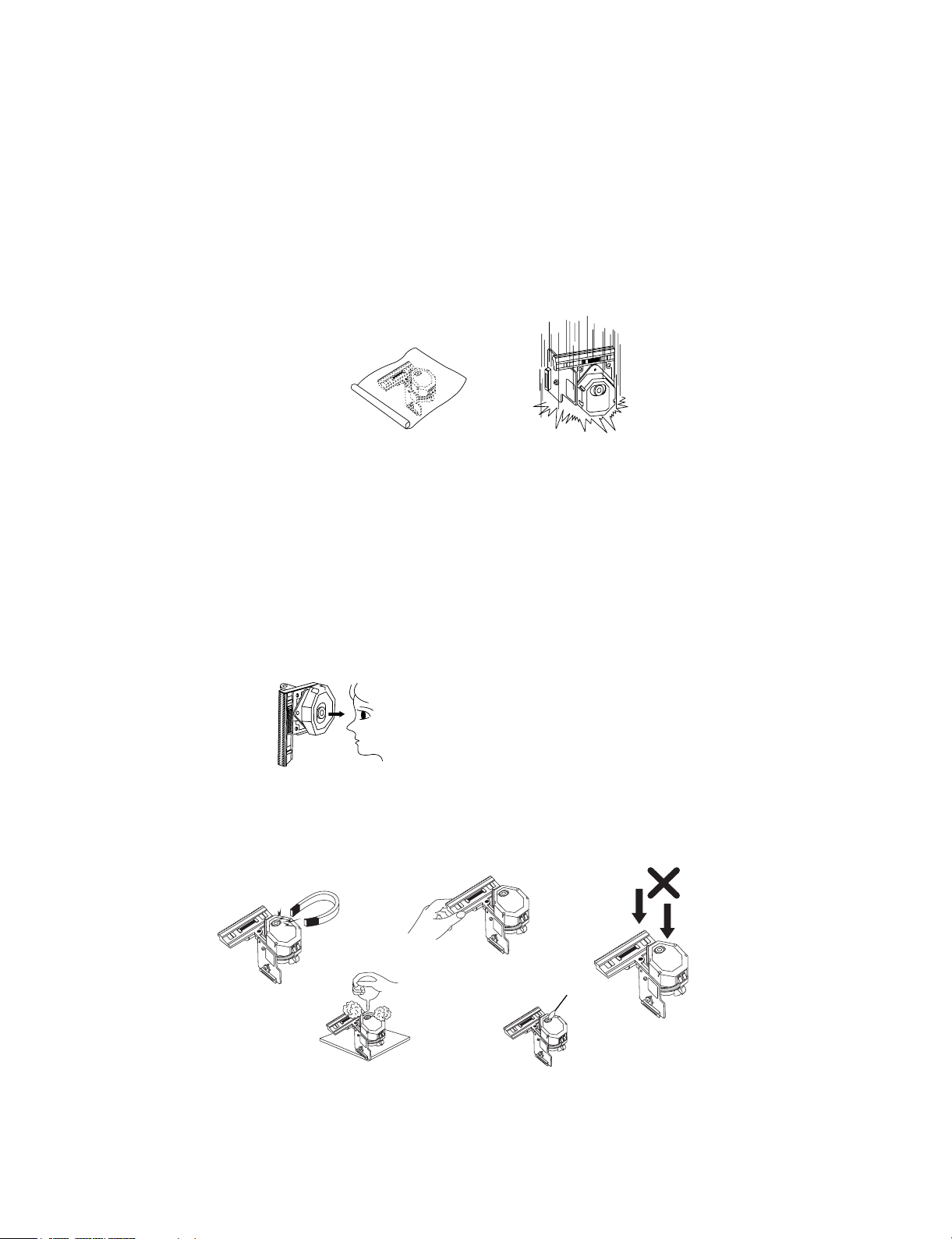
NOTES REGARDING HANDLING OF THE PICK-UP
1. Notes for transport and storage
1) The pick-up should always be left in its conductive bag until immediately prior to use.
2) The pick-up should never be subjected to external pressure or impact.
2. Repair notes
1) The pick-up incorporates a strong magnet, and so should never be brought close to magnetic materials.
2) The pick-up should always be handled correctly and carefully, taking care to avoid external pressure and
impact. If it is subjected to strong pressure or impact, the result may be an operational malfunction and/or
damage to the printed-circuit board.
3) Each and every pick-up is already individually adjusted to a high degree of precision, and for that reason
the adjustment point and installation screws should absolutely never be touched.
4) Laser beams may damage the eyes!
Absolutely never permit laser beams to enter the eyes!
Also NEVER switch ON the power to the laser output part (lens, etc.) of the pick-up if it is damaged.
5) Cleaning the lens surface
If there is dust on the lens surface, the dust should be cleaned away by using an air bush (such as used
for camera lens). The lens is held by a delicate spring. When cleaning the lens surface, therefore, a
cotton swab should be used, taking care not to distort this.
6) Never attempt to disassemble the pick-up.
Spring by excess pressure. If the lens is extremely dirty, apply isopropyl alcohol to the cotton swab. (Do
not use any other liquid cleaners, because they will damage the lens.) Take care not to use too much of
this alcohol on the swab, and do not allow the alcohol to get inside the pick-up.
- 1-2 -
Storage in conductive bag
Drop impact
NEVER look directly at the laser beam, and don’t let
contact fingers or other exposed skin.
Magnet
How to hold the pick-up
Pressure
Pressure
Cotton swab
Conductive Sheet
NOTES REGARDING COMPACT DISC PLAYER REPAIRS
1. Preparations
1) Compact disc players incorporate a great many ICs as well as the pick-up (laser diode). These
components are sensitive to, and easily affected by, static electricity. If such static electricity is high
voltage, components can be damaged, and for that reason components should be handled with care.
2) The pick-up is composed of many optical components and other high-precision components. Care must
be taken, therefore, to avoid repair or storage where the temperature of humidity is high, where strong
magnetism is present, or where there is excessive dust.
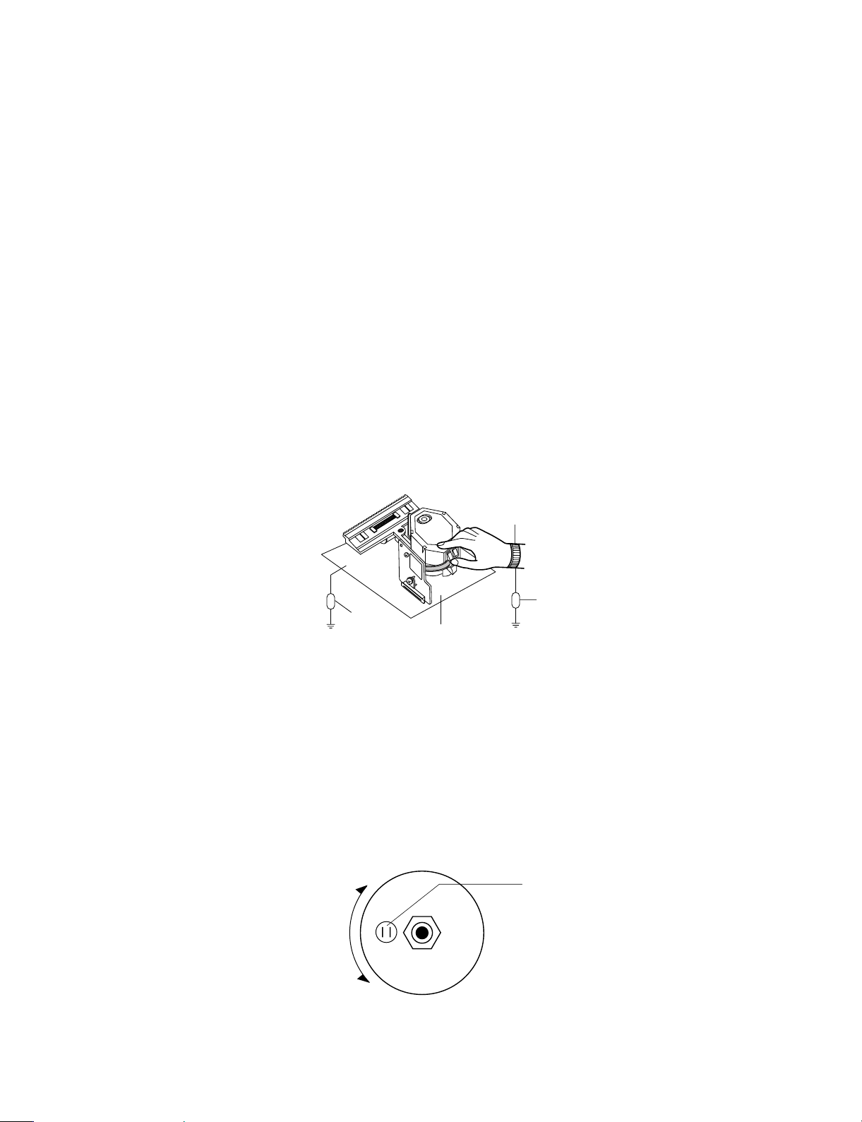
2. Notes for repair
1) Before replacing a component part, first disconnect the power supply lead wire from the unit
2) All equipment, measuring instruments and tools must be grounded.
3) The workbench should be covered with a conductive sheet and grounded.
When removing the laser pick-up from its conductive bag, do not place the pick-up on the bag. (This is
because there is the possibility of damage by static electricity.)
4) To prevent AC leakage, the metal part of the soldering iron should be grounded.
5) Workers should be grounded by an armband (1MΩ)
6) Care should be taken not to permit the laser pick-up to come in contact with clothing, in order to prevent
static electricity changes in the clothing to escape from the armband.
7) The laser beam from the pick-up should NEVER be directly facing the eyes or bare skin.
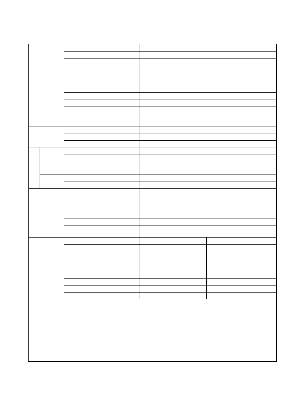
CLEARING MALFUNCTION
You can reset your unit to initial status if malfunction occur(button malfunction, display, etc.).
Using a pointed good conductor(such as driver), simply short the RESET jump wire on the inside of the
volume knob for more than 3 seconds.
If you reset your unit, you must reenter all its settings(stations, clock, timer)
NOTE: 1. To operate the RESET jump wire, pull the volume rotary knob and release it.
2. If you wish to operate the RESET jump wire, it is necessary to unplug the power cord.
- 1-3 -
Armband
Conductive
Sheet
Resistor
(1 Mohm)
Resistor
(1 Mohm)
VOLUME KNOB
UP
DOWN
VOLUME
RESET jump wire

ESD PRECAUTIONS
Electrostatically Sensitive Devices (ESD)
Some semiconductor (solid state) devices can be damaged easily by static electricity. Such components
commonly are called Electrostatically Sensitive Devices (ESD). Examples of typical ESD devices are integrated
circuits and some field-effect transistors and semiconductor chip components. The following techniques should
be used to help reduce the incidence of component damage caused by static electricity.
1. Immediately before handling any semiconductor component or semiconductor-equipped assembly, drain off
any electrostatic charge on your body by touching a known earth ground. Alternatively, obtain and wear a
commercially available discharging wrist strap device, which should be removed for potential shock reasons
prior to applying power to the unit under test.
2. After removing an electrical assembly equipped with ESD devices, place the assembly on a conductive
surface such as aluminum foil, to prevent electrostatic charge buildup or exposure of the assembly.
3. Use only a grounded-tip soldering iron to solder or unsolder ESD devices.
4. Use only an anti-static solder removal device. Some solder removal devices not classified as "anti-static" can
generate electrical charges sufficient to damage ESD devices.
5. Do not use freon-propelled chemicals. These can generate electrical charges sufficient to damage ESD
devices.
6. Do not remove a replacement ESD device from its protective package until immediately before you are ready
to install it. (Most replacement ESD devices are packaged with leads electrically shorted together by
conductive foam, aluminum foil or comparable conductive materials).
7. Immediately before removing the protective material from the leads of a replacement ESD device, touch the
protective material to the chassis or circuit assembly into which the device will by installed.
CAUTION : BE SURE NO POWER IS APPLIED TO THE CHASSIS OR CIRCUIT, AND OBSERVE ALL OTHER
SAFETY PRECAUTIONS.
8. Minimize bodily motions when handing unpackaged replacement ESD devices. (Otherwise harmless motion
such as the brushing together of your clothes fabric or the lifting of your foot from a carpeted floor can
generate static electricity sufficient to damage an ESD device).
- 1-4 -
- 1-5 -
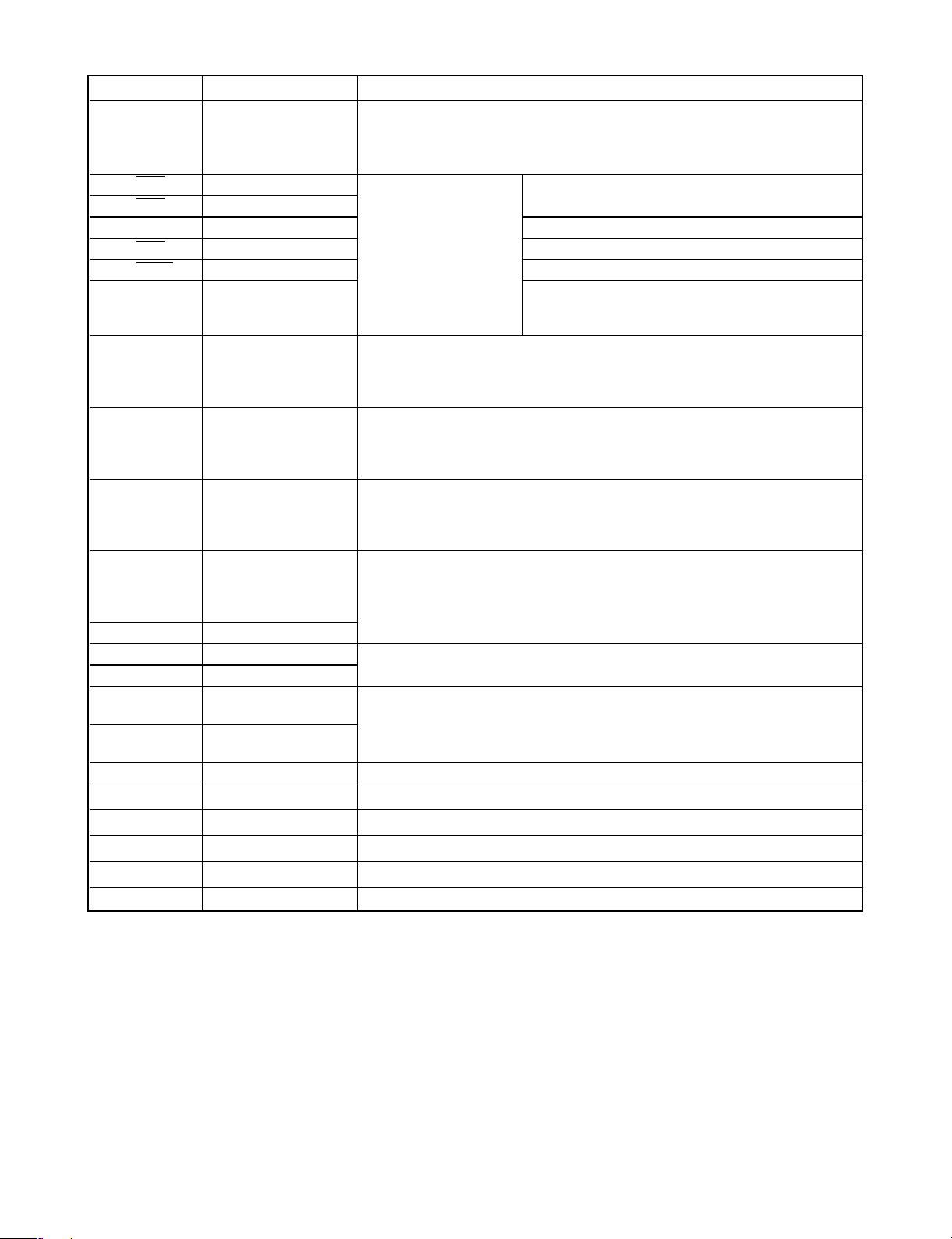
SPECIFICATIONS
Power supply AC 220~240V, 50/60Hz
Power consumption 70W
[General]
Mass 10.2 Ibs(4.6kg)
External dimensions (W x H x D) 360 x 82 x 388mm(14.2 x 3.2 x 15.3 inches)
Operating conditions Temperature: 5˚C to 35˚C, Operation status: Horizontal
Operating humidity 5% to 90%
Laser Semiconductor laser, wavelength 650nm
Signal system PAL 625/50, NTSC 525/60
Frequency response(audio) 4 Hz to 20 kHz
[CD/DVD] Signal-to-noise ratio(audio) More than 90dB(1kHz, NOP, 20kHz LPF/A-Filter)
Dynamic range (audio) More than 95dB
Harmonic distortion(audio) 0.15% (1kHz, at 12W position)
Video input 1.0V (p-p), 75Ω, negative syne., RCA jack
[Video] Video output 1.0V (p-p), 75Ω, negative sync., RCA jack
S-video output
(Y) 1.0V (p-p), 75Ω, negative sync., Mini DIN 4-pin
x
1 (C) 0.3V (p-p), 75Ω
Tuning Range 87.5 ~108MHz
FM
Intermediate Frequency 10.7MHz
Signal-to Noise Ratio 50dB
Frequency Response 150~12,000Hz
AM(MW)
Tuning Range 530 ~1,810kHz
Intermediate Frequency 450MHz
Stereo mode 30W + 30W(8Ω at 1kHz, THD 1%)
[Amplifier]
Surround mode Front: 30W+30W
Center*: 30W
Surround*: 30W +30W(8Ω at 1Hz, THD 1%)
Subwoofer*: 30W(8Ω at 60Hz, THD 1%)
Inputs VIDEO 1, 2
Outputs VIDEO 1(AUDIO OUT): 2V
WOOFER: 2V
Satellite Speaker (FE-3500TE) Passive Subwoofer(FE-3500WE)
Type 1 Way 1 Speaker 1 Way 1 Speaker
Impedance 8Ω 8Ω
[Speakers] Frequency Response 120~20,000Hz 35~1,000Hz
Sound Pressure Level 84dB/W(1m) 83dB/W(1m)
Rated Input Power 30W 30W
Max. Input Power 60W 60W
Net Dimensions (W x H x D) 90 x 125 x 106mm 160 x 350 x 325mm
Net Weight 0.7kg 4.78kg
[Supplied
Accessories]
• Audio cable.......................................................................................................................................... 1
• Speakers ............................................................................................................................................. 6
• Remote control .................................................................................................................................... 1
• AM Ioop antenna ................................................................................................................................. 1
• Video cable.......................................................................................................................................... 1
• Speaker cables.................................................................................................................................... 5
• Batteries .............................................................................................................................................. 2
• FM antenna ......................................................................................................................................... 1
* Depending on the sound mode
settings and the source, there may
be no sound output.
[Tuner]
- 1-6 -
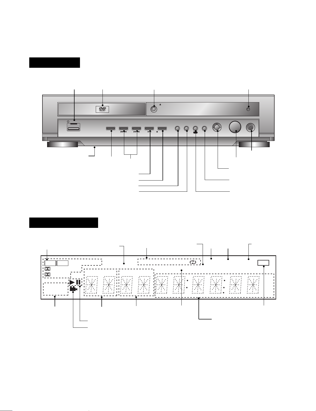
LOCATION OF CUSTOMER CONTROLS
STANDBY/ON
FUNCTION TUNE/SKIP PLAY/PAUSE
OPEN/CLOSE
MEMORY TITLE
FM/AM MONO/ST.
STOP/CLEAR
MENU RETURN ENTER
VOL
PHONES
MENU/PREST
RDS
Disc Tray
FUNCTION
button
SKIP/TUNE
buttons
PHONE connector
MENU(MONO/STEREO) button
ENTER button
RETRUN (RDS) button
VOLUME controller
ARROW/PRESET
joy stick
PALY/PAUSE button
STOP (MEMORY/CLEAR) button
TITLE (FM/AM)button
RESET button (located at
the bottem, see page 46.)
OPEN/CLOSE button Remote sensor
POWER button
and indicator
PCM
MUTE
DIGITAL
PRO LOGIC
DVD
CD
VCD
MP3
HALL1
THEATER
HALL2
dts
RDS
TITLE
REPEAT
CHP/TRK
MEMORY PROGRAM
ms
dB
MHz
kHz
ALL
ABSLEEP
TUNED STEREO
Sound mode
indicator
RDS indicator
PROGRAM
indicator
SLEEP
indicator
TUNED
indicator
STEREO
indicator
MUTE indicator
MEMORY
indicators
Chapter/Track
number indicator
Title number
indicator
PALY/PAUSE indicator
Angle icon indicator
Disc indicator
Total playing time/Elapsed time/
Frequency/Delay time/
Volume etc. indicators
Repeat playback
mode indicators
FRONT PANEL
DISPLAY WINDOW
- 1-7 -
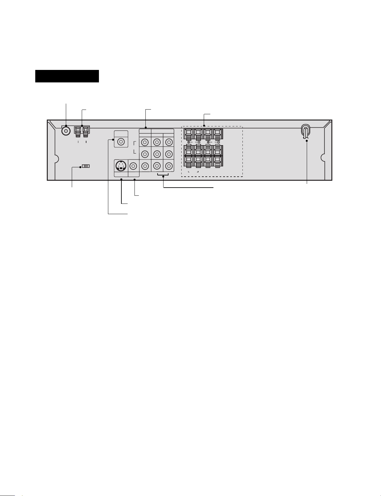
FM 75Ω Coaxial Antenna Connector
MONITOR OUT Connector
AM Antenna
Connector
SPEAKER Connectors
VIDEO 1(Input/Output)
Connectors
VIDEO 2(Input)
Connectors
S-VIDEO OUT Connector
WOOFER OUT Connector
POWER CORD Connect to an
AC 230V, 50Hz outlet only.
VIDEO SELECTOR
Switch
R L
FM
75‰
GND AM
AUTO-NTSC-PAL
VIDEO
SELECTION
S-VIDEO
OUT
AUDIO
L
R
WOOFER
OUT
VIDEO 2
VIDEO
IN IN
R
REAR
(8
‰
)
WOOFER
(8
‰
)
CLEAR
FRONT
SPEAKER
(8‰)
(8‰)
L
OUT
VIDEO 1
MONITOR
OUT
REAR PANEL
- 1-8 -
REAR PANEL
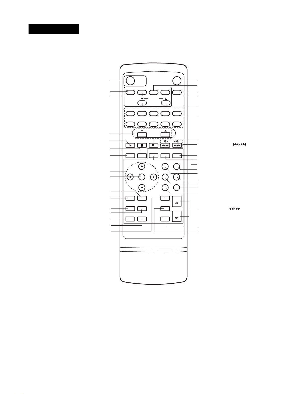
• you will find instructions for each of the remote control functions in the appropriate sections of this instruction
manual.
POWER
MUTE
FM/AM
CD/DVD VIDEO 1
PRESET
VOLUME
PLAY
PROG. REPEAT.
PAUSE
STEP
TEST
TONE
SOUND
MODE
BY PASS
LEVEL
DISPLAY
SET-UP
AUDIO
REV.
FWD
ENTER
ANGLE
S-TITLE
REPEAT
ZOOM
CLEAR
SEARCH
MARKER
SLOW SCAN
TITLE
A - B
MENU
RETURN
DELAY
STOP
SKIP
13245
68790
VIDEO 2 SLEEP
POWER button
MUTE button
VIDEO 1 buttonVIDEO 1 button
SLEEP button
VIDEO 2 buttonVIDEO 2 button
NUMBER buttons
STOP button
BY PASS button
SOUND MODE button
TEST TONE button
DELAY button
LEVEL button
RETURN button
DISPALY button
*MENU button*MENU button
SET-UP button
SEARCH button
MARKER button
SLOW SCAN ( ) buttons
SKIP(*SEARCH) button
PREST(▲/▼) buttons
FM/AM button
CD/DVD button
VOLUME(▲/▼) buttons
PAUSE button
PROGRAM buttons
**ARROW buttons
ENTER button
ANGLE button
SUBTITLE button
REPEAT A-B button
ZOOM button
***TITLE button
CLEAR button
AUDIO button
PLAY button
*MENU button
Use the MENU button to display the menu screen included on DVD video discs.
***TITLE button
Use the TITLE button to display the title screen included on DVD video discs.
**Directional arrow buttons
(up, down, left, right) for use in highlighting a selection on a GUI menu screen, TITLE and MENU screen.
* Press and hold button for about two seconds for search function.
- 2-1 -
SECTION 2. AUDIO PART
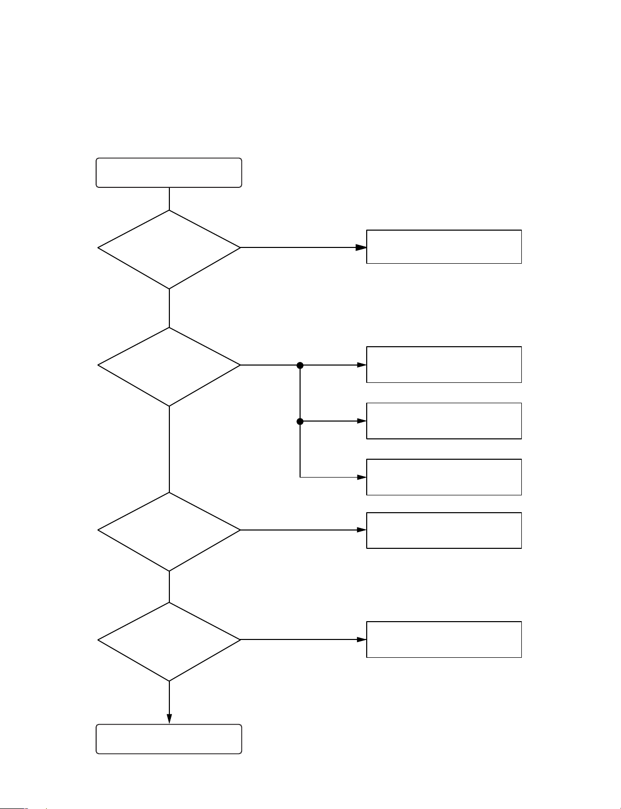
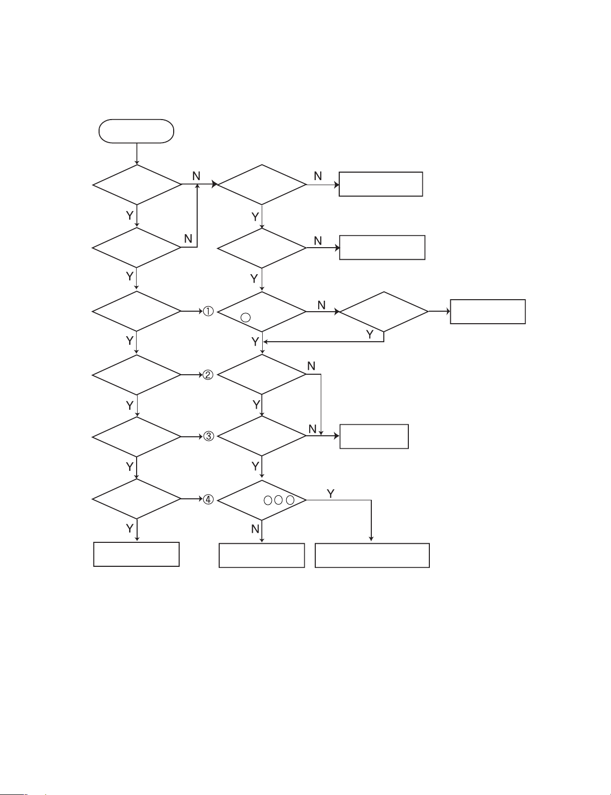
ELECTRICAL TROUBLESHOOTING GUDIE
Turn power on.
Is power on?
Does initial read work?
Does it play?
Does it output audio?
Check power supply circuit.
Check laser circuit.
Check focus circuit.
Check disc.
Check tracking servo circuit.
Check audio circuit.
OK
YES
YES
YES
YES
NO
NO
NO
NO
1.
- 2-2 -
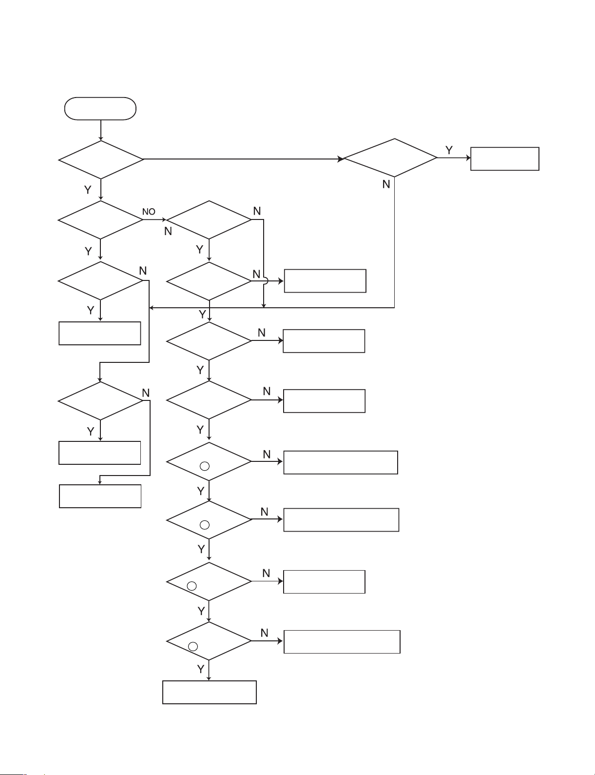
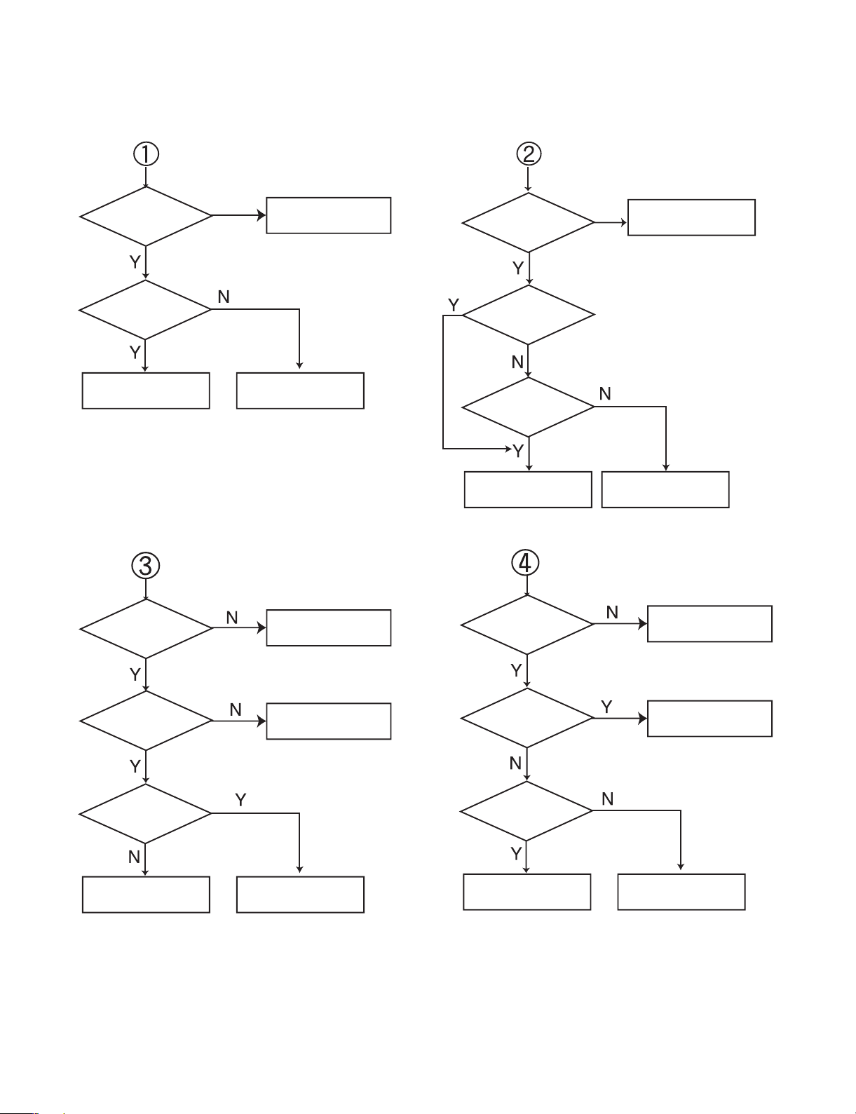
2. AUDIO µ. COM Circuit
POWER ON
Does CD/DVD
appear at FLT?
Does LOADING
appear at FLD?
Does it appear
DVD Error at
FLD?
Does Video1/2
FM 87.5 appear
at FLD?
OK.
Check
Connector(CN103)if
is normally.
Reconnet it.
Refer to SMPS
Refer to oscillator
Circuit.
Check DVD Reset Waveform.
Check IC101 Reset Wavefrom.
Check 3.3V line.
Check Power dection Circuit..
Check power part
of Main B/D.
Check oscillator
of x101.
Check if CN103
Pin is High.
Check if IC101
Pin is High.
Check if IC101 Pin
is high (3.3r).
Check if IC101 Pin
is High .
Replace IC 101.
Does no Dise or
Time appear at FLD?
Check if DVD an Audio
Micom Interface is OK.
Check power.
Check DVD Module.
Check SMPS.
42
30
3
63
- 2-3 -
3. Front Circuit (1/2)
POWER ON
LED OFF.
Is digitron
on normally?
Check if
the CN401
is OK.
Check if the
Front power is
OK(*1).
Check
if the IC401 OSC Pin
Wavefrom is
OK.
Check if the
IC401 Pins
is OK(*2).
Check if the
R 427
OK.
Replace
R 427.
Refer to SMPS Part.
Reconnec it.
Check if the
VFD401 Pins
are OK.
Check
IC401 Pins , ,
Wavefrom
Refer to Micom Circuit.
Check Patten
and Resoldering.
Replace IC401.
Check if all Buttens
are OK.
Check if the
Volume is
OK.
Check if the
Headphone is
OK.
Check if the
Remocon is
OK.
Front B/D OK.
* 1: CN401 Pins
Pin 13: +5V
Pin 14: -32V
Pin 15: -28V
Pin 16: -32V
* 2: CN401 Pins
Pin 14: +5V
Pin 133: -32V
* 3: VFD401 Pins
F11 : -28V
F22 : -32V
52
5
6
7
- 2-4 -
Front Circuit (2/2)
Check
if the Power part of the
Front is OK.
Check if the
Power part of the
Front is OK.
Check if
R401~R415
OK.
Check if
CN401 Pins3, 4
Waverfrom
OK.
Check if
R430, R431
OK.
Refer to Micom
Circuit
Refer to Micom
Circuit.
Refer to
power(SMPS).
Refer to
power(SMPS).
Refer to SMPS part.
Refer to SMPS.
Replace R401~R415.
Replace R430, R431.
Check
if the Power part of the
Front is OK.
Check if the
Power Part of the
Front is OK.
Check if the
RMC401Volume
is OK (5V).
Check if the
Remocon waveform of
the CN401.
Check if the
CN401 pin11
is Low.
Check if
headphoneJack
in JK401 is
OK.
Refer to M-COM
Circuit.
Check Main B/D.
Replace RMC 401.
Check RMC Circuit.
Refer to Micom
Circuit.
Check JK401 Circuit.

- 2-5 -
DVD PLAYER PROGRAM DOWNLOAD METHOD
1. DVD player without CD-RW option
1-1) Download the DVD program from your PC as following procedure
ACTION FLD display
• Plug the Power cord out
• Connect the Fixture for download
(Refer to Deck Mechanism Adjustment)
• Execute the prgram for download(Flashrom.exe)
• Open the DVD program file
• Plug the Power cord in
• Press the MENU Key on the Remote controller FLASH
• Select Down icon with injector icon then start
download from the P.C
■ In status of download
• Erased the Flash memory FLASH ERA
• Written the Flash memory FLASH XX(XX: Program counter)
• Verified the Flash memory FLASH XX(XX: Program counter)
• Completed the download FINISHED
■ If an error was occurred during download, do not unplug the Power cord, and retry the download
form the P.C until it is completed.
2. DVD player with CD-RW option(for models using C-CUBE
MPEG chip, marking on the IC is ZIVA)
2-1) Make the DVD program upgrade Disc as following procedure
*Recommended S/W: adaptec Easy CD Creater
*use file format: ISO9660
• Rename the souce file from the P.C to FIRMWARE.BIN
(Ex, If Source file is lg_a3_korea.bin, rename to FIRMWARE.BIN)
• Format the CD-RW Disc as below Make the Folder name to UPGRSADE.DVD under root folder
(Ex, UPGRADE.DVD)
• Download the source file renamed to FIRMWARE.BIN in the folder
(Ex, UPGRADE.DVD FIRMWARE.BIN)
WW
W

- 2-6 -
2-2) Insert the upgrade Disc into the DVD player slot, then the DVD player reads the
Disc and upgrade the Firmware itself as followings
Status FLD display on DVD player
• Detect the upgrade Disc No display
• Read the Disc Cd rEAD XX(XX: Program counter)
• Erased the Flash memory FLASH ERA
• Written the Flash memory FLASH XX(XX: Program counter)
• Verified the Flash memory FLASH XX(XX: Program counter)
• Completed the upgrade FINISHED
Note: After completed, plug the Power cord out and in again, and then press the Open key, then the
Disc will be ejected.
Caution: While CD detecting and reading, if Open key or Power is pressed Then download
procedure will be aborted.
3. DVD player with CD-RW option
(for models using NS MPEG chip, marking on the IC is PANTERA)
3-1) Make the DVD program upgrade Disc as following procedure
*Recommended S/W: adaptec Easy CD Creater
*use file format: ISO9660
• Format the CD-RW Disc as below.
Make the Folder name to “lg_dvd UPGRADE lg” under root folder
( lg_dvd_firmware upgrade lg)
• Download the source file in the folder
(Ex, If the source file is “lg_a3_korea.bin, “lg_dvd firmware upgrade lg lg_a3_korea.bin”)
3-2) UPgrade the firmware for DVD player as followings
ACTION FLD display on dvd player
• Insert the upgraded Disc into the DVD player solt Press Up
then starts the detecting
• Press the UP key on the Remote controller READ 0(If error is occurred, displayed
then starts the reading retry counter)
- Starts the upgrading UPGRADE 0(If error is occurred, displayed
retry counter)
- Completed the upgrading FINISHED ➞ checksum
- Opened the Tray Disc (“FINISHED ➞ checksum” is displayed
repeatedly at 2 second intervals)
• Plug the Power Cord out
Note: In the status of FLD with “READ 0” or “UPGRADE 0”
If an error is occured, the read counter, “READ 0”, shows retry counter or “ERROR num”
If the num has 0~2, retry the firmware upgrade procedure.
If the error is continued after retrying 5 times, replace the Flash ROM IC.
W W W
W W
W W W W
- 2-7 -
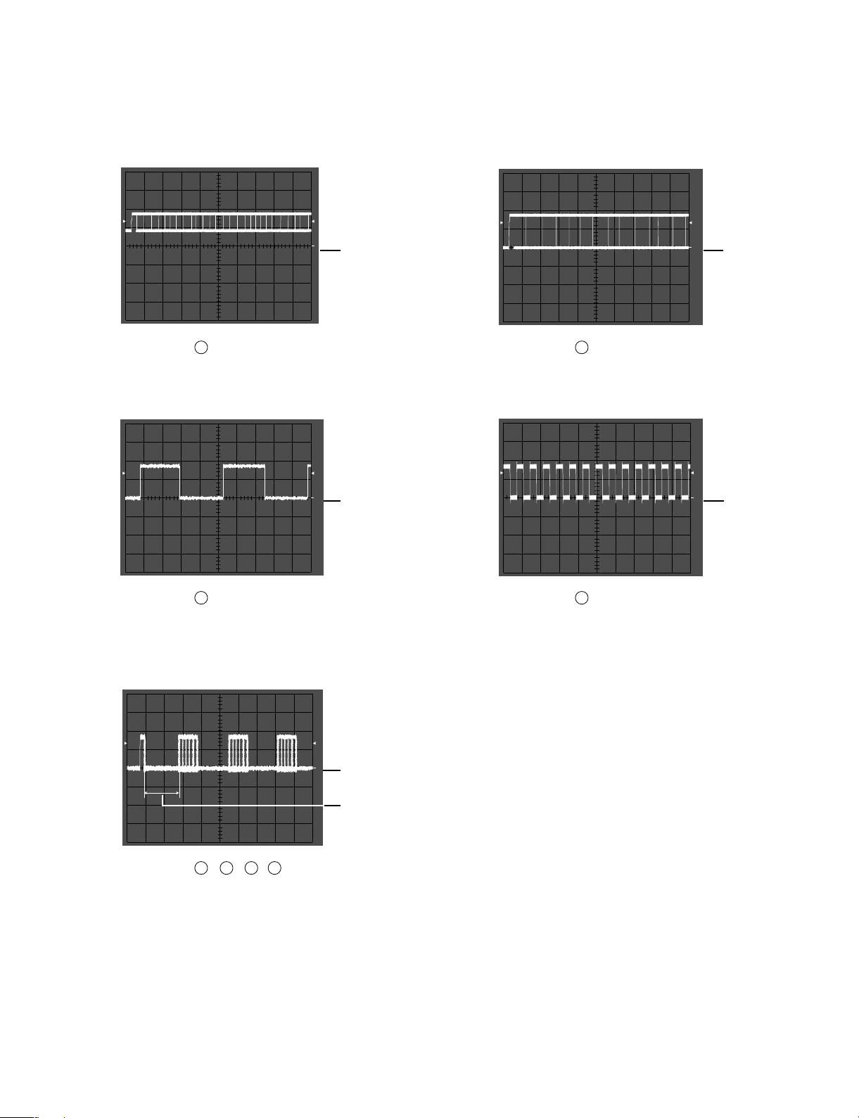
WAVEFORMS OF MAJOR CHECK POINT
• IC 703 pin
• SPDIF signal woveform during normal play.
• IC 703 pin
• Serial data output wavefrom during normal
play.
1
1
(
2V/Div.
500nS/Div.
OV
(
2V/Div.
500nS/Div.
OV
(
2V/Div.
500nS/Div.
OV
384kHz
(
2V/Div.
500nS/Div.
OV
(
2V/Div.
500nS/Div.
OV
1) 2)
4
18
• IC 202 pin
• L/R clock data input wavefrom during
normal operation.
• IC 202 pin
• Bit clock data input waveform during
normal operation.
1
1
3) 4)
3
4
• IC 202 pin , , ,
• PWM data output wavefrom during normal
operation.
1
5)
27
28 29
30
- 2-8 -
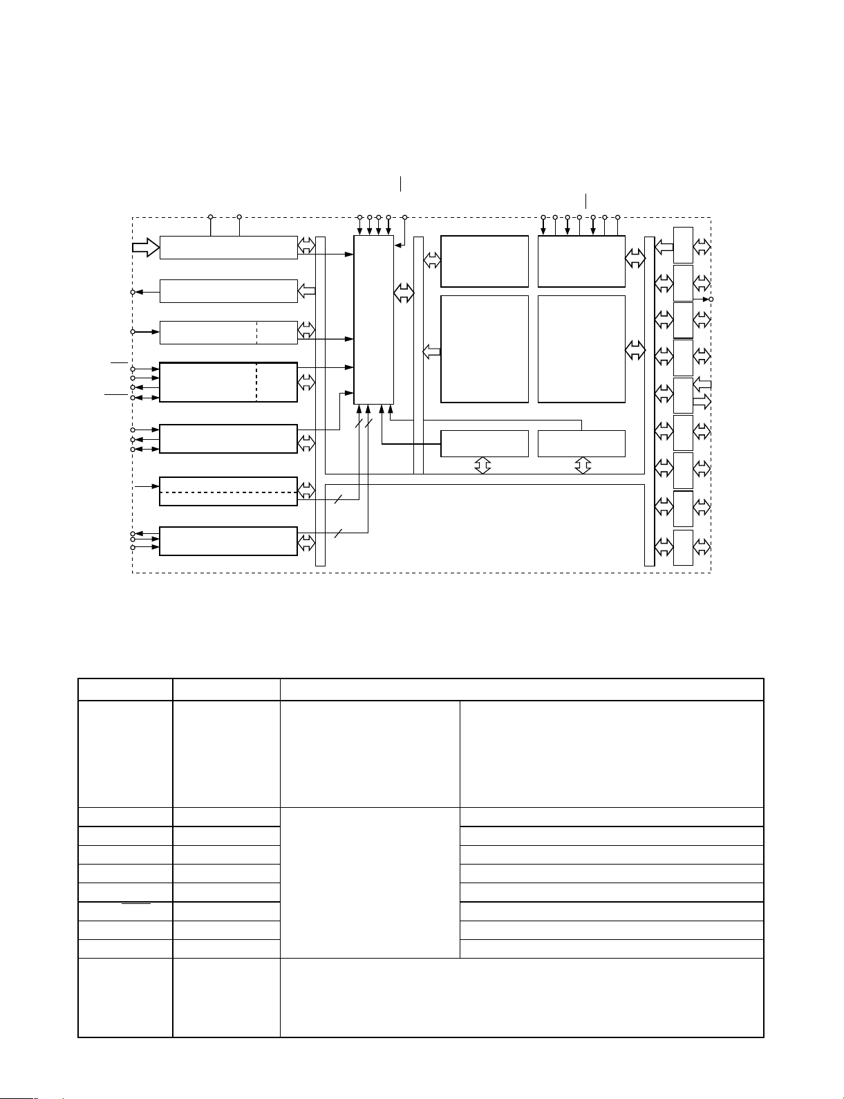
INTERNAL BLOCK DIAGRAM OF ICs
■ CXP 84332
■ PIN DESCRIPTION
A/D CONVERTERAN0 to AN7
8
AVss
AV
REF
PI0/INT0
INTERRUPT CONTROLLER
PI1/INT1
PI2/INT2
PI3/INT3
PE3/NMI
PE4/PWM
PE2/RMC
PB1/CS0
PB3/SI0
PB4/SO0
PB2/SCK0
PB6/SI1
PB7/SO1
PB5/SCK1
PE0/EC0
PE5/TO
PB0/CINT
PE1/EC1
14 BIT PWM GENERATOR
REMOCON
SPC700
CUP CORE
CLOCK GEN./
SYSTEM CONTROL
PA0 to PA7
PB0 to PB6
PB7
PC0 to PC7
PD0 to PD7
PE0 to PE3
PE4 to PE5
PF0 to PF7
PG0 to PG7
PH0 to PH7
PI0 to PI7
TEXTXEXTAL
XTAL
RST
VDDV
SS
PORT A
ROM
32K/40K BYTES
PRESCALER/
TIME BASE TIMER
32kHz
TIMER/COUNTER
RAM
1120 BYTES
SERIAL INTERFACE UNIT 1
16 BIT CAPTURE
8 BIT TIMER 1
8 BIT TIMER/COUNTER 0
TIMER/COUNTER 2
FIFO
FIFO
SERIAL
INTERFACE
UNIT 0
PORT BPORT CPORT D PORT EPORT FPORT GPORT HPORT I
8
8
8
8
8
4
2
8
8
7
2
2
2 2
symbol I/O Description
PA0/AN0
to
I/O/Analog input Analog inputs to A/D converter.(8 pins)
PA7/AN7
PB0/CINT I/O/Input External capture input to 16-bit timer/counter.
PB1/CS0 I/O/Input Chip select input for serial interface(CH0).
PB2/SCK0 I/OI/O Serial clock I/O (CH0).
PB3/SI0 I/O/Input Serial data input (CH0).
PB4/SO0 I/O/Output Serial data Output (CH0).
PB5/SCK1 I/OI/O Serial clock I/O (CH1).
PB6/SI1 I/O/Input Serial data input (CH1).
PB7/SO1 Output/Output Serial data Output (CH1).
PC0 to PC7 I/O
(Port C)
8-bit I/O port. I/O can be set in a unit of single bits. Capable of driving 12mA sink
current. Incorporation of Pull-up resistor can be set through the software in a unit
of 4 bits.
(8 pins)
(Port A)
8-bit I/O port. I/O can be set in
a unit of single bits.
Incorporation of the pull-up
resistance can be set through
the software in a unit of 4 bits.
(8 pins)
(Port B)
Lower 7-bit I/O port in which
I/O can be set in a unit of
single bits. Also, an
uppermost bit (PB7)
exclusively for output.
Incorporation of pull-up
resistor can be set through the
software in a unit of 4 bits.
(8 pins)
- 2-9 -
symbol I/O Description
PD0 to PD7 I/O
PE0/EC0 Input/Input
External event inputs for timer/counter.(2 pins)
PE1/EC1 Input/Input
PE2/RMC Input/Input Remote control reception circuit input.
PE3/NMI Input/Input Non-maskable interruption request input.
PE4/PWM Output/Output 14-bit PWM output.
PE5/TO/ADJ Output/Output/Output
Rectangular wave output for 16-bit timer/counter.
Output for 32kHz oscillation frequency
demultiplication.
PE0 to PF7 I/O
(Port F)
8-bit I/O port. I/O can be set in a unit of single bits. Incorporation of pull-up
resistor can be set through the software in a unit of 4 bits
(8 pins)
PG0 to PG7 I/O
(Port G)
8-bit I/O port. I/O can be set in a unit of single bits. Incorporation of pull-up
resistor can be set through the software in a unit of 4 bits
(8 pins)
PH0 to PH7 I/O
(Port H)
8-bit I/O port. I/O can be set in a unit of single bits. Incorporation of pull-up
resistor can be set through the software in a unit of 4 bits
(8 pins)
I/O/Input
(Port I)
8-bit I/O port. I/O can be set in a unit of single bits. Incorporation of pull-up
resistor can be set through the software in a unit of 4 bits
(8 pins)
PI4 to PI7 I/O External interruption request inputs.
EXTAL Input Crystal connectors for system clock oscillation. When the clock is supplied
XTAL Output externally, input to EXTAL; opposite phase clock should be input to XTAL.
TEX Input
Crysal connectors for 32kHz timer/counter colck oscillation circuit.
Connect a 32kHz crystal oscillator between TEX and TX.
TX Output
For usage as event input, connect clock oscillation source to TEX,
and open TX.
RST Input Low-Ievel active, system reset.
NC NC. Under normal operating conditions, connect to V
DD
AV
REF
Input Reference voltage input for A/D converter.
AV
SS
A/D converter GND.
V
DD
Positive power supply.
V
SS
GND
(Port E)
6-bit port. Lower 4 bits
are for inputs; upper 2
bits are for outputs.
Incorporation of pull-up
resistor can be set
through the software.
(8 pins)
(Port D)
8-bit I/O port. I/O can be set in a unit of single bits. Incorporation of pull-up
resistor can be set through the software in a unit of 4 bits.
(8 pins)
PI0/INT0
to
PI3/NT3
 Loading...