

Page 1

W ASHING MACHINE
SERVICE MANUAL
READ THIS MANUAL CAREFULLY TO DIAGNOSE
PROBLEMS CORRECTLY BEFORE SERVICING THE UNIT.
MODEL: CW2079CWD/CW2079CWN
CAUTION
!
Page 2

JUNE. 2007 PRINTED IN KOREA
P/No.: MFL30599105
Page 3

2
CONTENTS
1. IMPORTANT SAFETY INSTRUCTIONS.......................................................................................3
2. SPECIFICATIONS.........................................................................................................................4
3. FEATURES AND TECHNICAL EXPLANATION........................................................................... 5
4. PARTS IDENTIFICATION ............................................................................................................ 7
5. INSTALLATION INSTRUCTIONS................................................................................................. 8
6. OPERATION..........................................................................................................................14~16
7. WIRING DIAGRAM/PROGRAM CHART.....................................................................................17
8. TROUBLESHOOTING...........................................................................................................18~20
8-1. BEFORE PERFORMING SERVICE...................................................................................18
8-2. QC TEST MODE.................................................................................................................18
8-3. HOW TO CHECK THE WATER LEVEL FREQUENCY......................................................18
8-4. HOW TO CHECK THE RPM...............................................................................................18
8-5. ERROR DISPLAY ...............................................................................................................19
9. DIAGNOSIS AND TROUBLESHOOTING.............................................................................21~28
10. DISASSEMBLY INSTRUCTIONS .......................................................................................29~38
11. EXPLODED VIEW .....................................................................................................................39
11-1. CABINET & CONTROL PANEL ASSEMBLY....................................................................39
11-2. DRUM & TUB ASSEMBLY................................................................................................40
11-3. DISPENSER ASSEMBLY .................................................................................................41
Page 4

3
1. IMPORTANT SAFETY INSTRUCTIONS
READ ALL INSTRUCTIONS BEFORE USE
WARNING!
For your safety, the information in this manual must be followed to minimize the risk of fire
or explosion, electric shock, or to prevent property damage, personal injury, or loss of life.
IIMMPPOORRTTAANNTT
SSAAFFEETTYY IINNSSTTRRUUCCTTIIOONNSS
• Read all instructions before using the washer.
• Do not wash articles that have been previously
cleaned in, washed in, soaked in, or spotted with
gasoline, dry cleaning solvents, or other
flammable or explosive substances, as they give
off vapors that could ignite or explode.
• Do not add gasoline, dry cleaning solvents, or
other flammable or explosive substances to the
wash water. These substances give off vapors that
could ignite or explode.
• Under certain conditions, hydrogen gas may be
produced in a hot water system that has not been
used for 2 weeks or more. HYDROGEN GAS IS
EXPLOSIVE. If the hot water system has not been
used for such a period, before using the washing
machine, turn on all hot water faucets and let the
water flow from each for several minutes. This will
release any accumulated hydrogen gas. As the gas
is flammable, do not smoke or use an open flame
during this time.
• Do not allow children to play on or in the washer.
Close supervision of children is necessary when
the washer is used near children.
• Before the washer is removed from service or
discarded, remove the door to prevent children
from hiding inside.
• Do not install or store the washer where it will be
exposed to the weather.
• Do not tamper with controls.
• Do not repair or replace any part of the washer or
attempt any servicing unless specifically
recommended in the user-maintenance
instructions or published user-repair instructions
that you understand and have the skills to carry
out.
• See Installation Instructions for grounding
requirements.
• ALWAYS follow the fabric care instructions
supplied by the garment manufacturer.
• Do not place items exposed to cooking oil in your
washer. Items contaminated with cooking oils may
contribute to a chemical reaction that could cause
a load to catch fire.
• Do not use fabric softeners or products to
eliminate static unless recommended by the
manufacturer of the fabric softener or product.
WARNING: To reduce the risk of fire, electric shock, or injury to persons when using the washer, follow basic
precautions, including the following:
SSAAVVEE TTHHEESSEE IINNSSTTRRUUCCTTIIOONNSS
This appliance must be grounded. In the event of malfunction or breakdown, grounding will reduce the risk
of electric shock by providing a path of least resistance for electric current. This appliance is equipped with
a cord having an equipment-grounding conductor and grounding plug. The plug must be plugged into an
appropriate outlet that is properly installed and grounded in accordance with all local codes and ordinances.
• Do not use an adapter or extension cord.
• Do not remove ground prong.
• If you don’t have the proper outlet, consult an electrician.
GROUNDING INSTRUCTIONS
WARNING: Improper connection of the equipment-grounding conductor can result in risk of electric shock.
Check with a qualified electrician or serviceman if you are in doubt as to whether the appliance is
properly grounded. Do not modify the plug provided with the appliance - if it does not fit the outlet,
have a proper outlet installed by a qualified electrician.
!
!
!
Page 5
4
2. SPECIFICATIONS
MODEL CW2079CWD/CWN
COLOR BLUE WHITE
POWER SUPPLY 120V~, 60 Hz
PRODUCT WEIGHT 190 lbs. (86 kg)
WASHING 155 W
DRAIN MOTOR 80 W
WASH 45 rpm
SPIN
0-1000 rpm
CYCLES 4
OPTIONS ADD SUPER WASH Cycle
OPERATIONAL WATER PRESSURE 14.5-116 psi (100-800 kPa)
CONTROL TYPE Electronic
WASH CAPACITY [cu. ft.] 3.32 (IEC 3.83)
DIMENSIONS 27” (W) X 293/4” (D) X 3811/16” (H), 5013/16” (D, door open)
DOOR SWITCH TYPE PTC + Solenoid
WATER LEVEL 10 steps (by sensor)
LAUNDRY LOAD SENSING Incorporated
ERROR DIAGNOSIS Incorporated
ELECTRIC POWER
CONSUMTION
REVOLUTION SPEED
Page 6
5
3. FEATURES & TECHNICAL EXPLANA TION
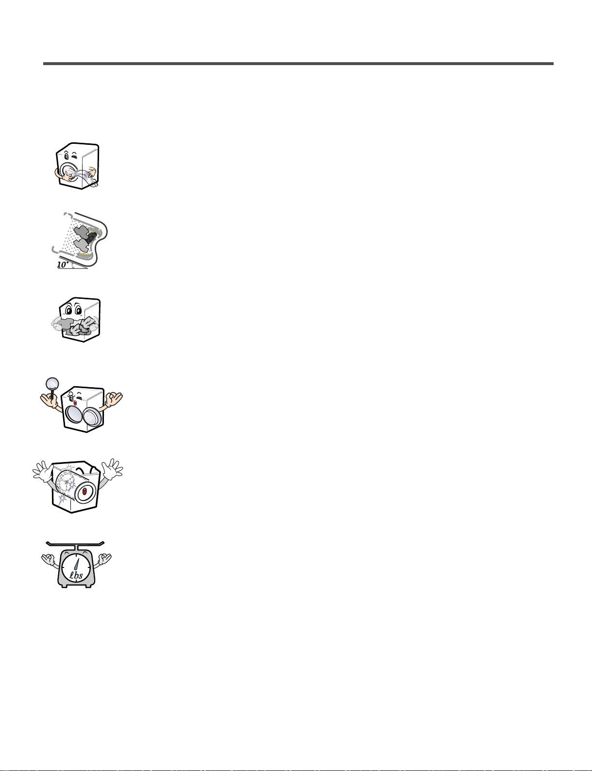
3-1. FEATURES
■ Direct Drive System
The advanced Brushless DC motor directly drives the drum
without belt and pulley.
■
The Tilted Drum and Extra Large Door Opening
Tilted drum and extra large door opening make it possible
to load and unload easily.
■
Ultra Capacity
The larger drum enables not just higher head drop and stronger centrifugal
force, but also less tangling and wrinkling of the laundry. Heavier loads, such
as king size comforters, blankets, and curtains, can be washed.
■
Large Door and Window
The large window lets you see the wash as it progresses.
■
The Stainless Steel drum
Stainless Steel Drum doesn't rust.
■
Automatic Wash Load Detection
Automatically detects the load and optimizes the washing time.
Page 7

6
3-2. WATER LEVEL CONTROL
● This model incorporates a pressure sensor which can sense the water level in the tub.
● The water supply is stopped when the water level reaches the preset level; then the selected cycle begins.
● Spinning does not proceed until the water in the tub drains to a certain level.
3-3. DOOR CONTROL
● The door can be opened by pulling the door handle whenever washer is not in operation.
● When the cycle is completed, the DOOR LOCKED light will turn off.
● If a power failure has occurred while in operation, the door will unlock after 2 minutes.
● Clicking sounds can be heard when the door is locked/unlocked.
3-4. THE DOOR CAN NOT BE OPENED
● While program is operating.
● While Door Lock lights turn on.
● While the drum is rotating.
3-5. DOOR LOCKED LAMP LIGHTS
● When the frequency of water level is lower than 22.9 kHz.
(It can be canceled when the frequency is more than 23.8 kHz.)
● When the temperature inside the tub is higher than 45° C (104° F) and water level is not 25.5 kHz.
(It can be canceled when the water level is 25.5 kHz or the temperature inside the tub is lower than
40° C (113° F). )
Page 8
7
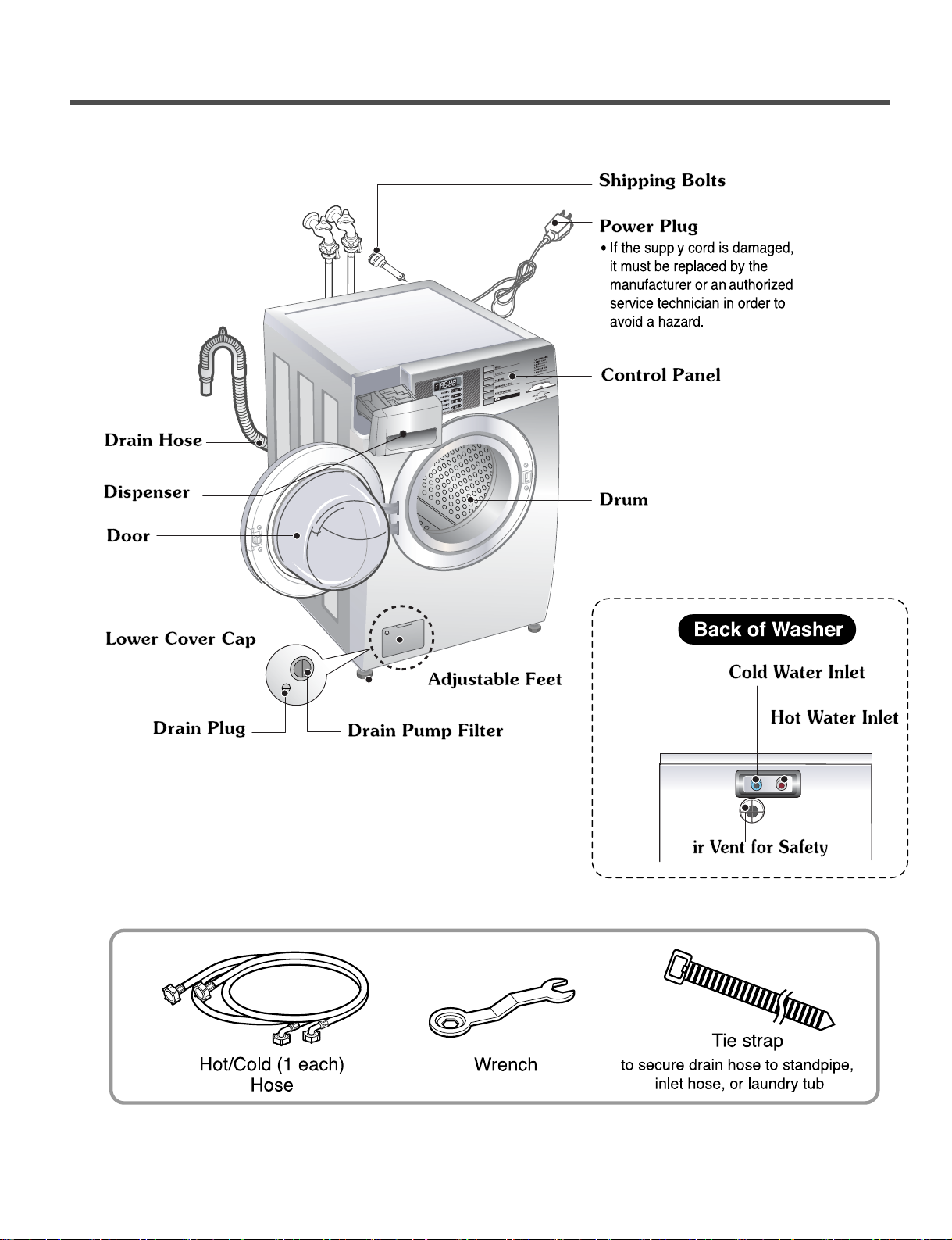
4. PARTS IDENTIFICATION
■ ACCESSORIES
A
Page 9
8
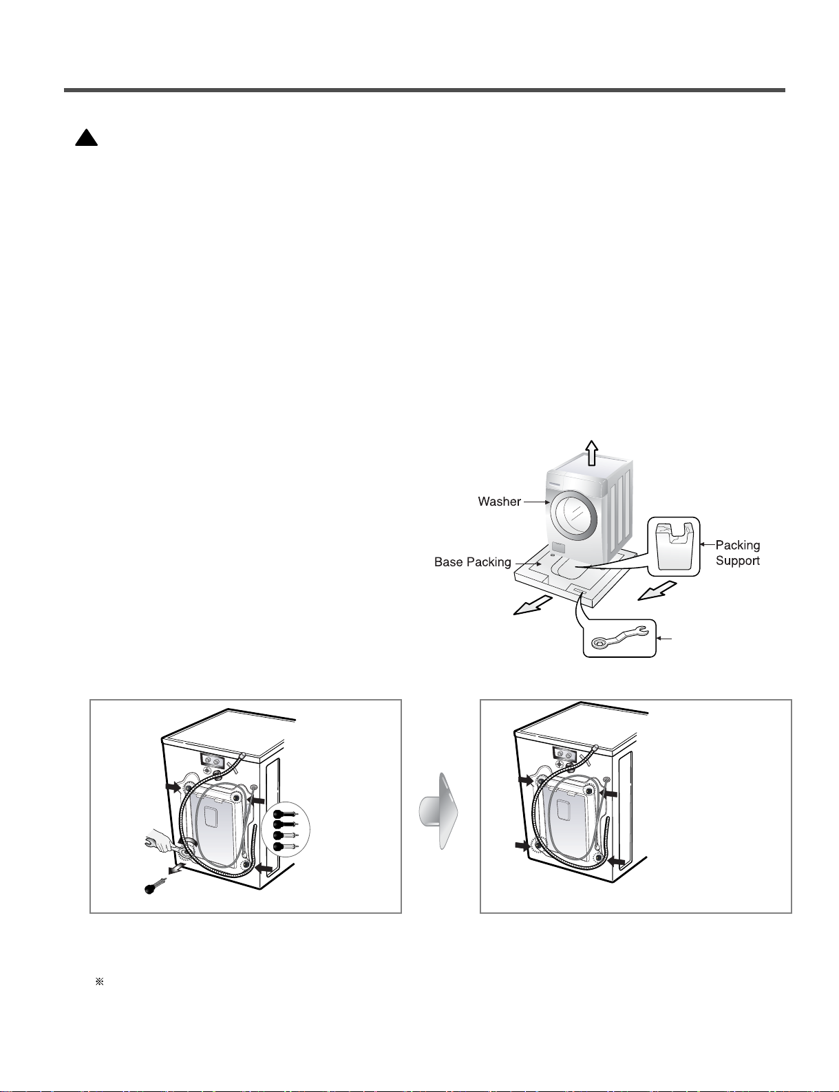
5. INSTALLATION INSTRUCTIONS
Unscrew the 4 bolts with the wrench supplied
Take out the 4 bolts by twisting the braces slightly
Keep the
4 bolts and the wrench for future use
(Whenever the appliance is transported, the
shipping bolts and braces must be replaced.)
Close the holes with the caps supplied.
The appliance is fitted with shipping bolts to prevent
internal damage during transportation.
Packing and all shipping bolts must be removed
before using the washer.
☞ When unpacking the base, be sure to remove
the additional packing support in the middle of
the base packing.
■ Shipping bolts
• Washer is heavy. Two or more people may be needed to install and move the appliance.
Failure to do so can result in back or other injury.
• Store and install the washer where it will not be exposed to temperatures below freezing or exposed to
outdoor weather conditions. Failure to follow this warning can cause serious injury, fire, electrical shock, or
death.
• This appliance must be properly grounded for personal safety. Properly ground washer to conform with all
governing codes and ordinances. Failure to follow this warning can cause serious injury, fire, electrical shock,
or death.
• Do not install the washer in humid spaces to reduce the risk of electric shock. Failure to follow this
warning can cause serious injury, fire, electrical shock or death.
• The base opening must not be obstructed by carpeting when the washer is installed on a carpeted floor.
• Do not remove ground prong. Do not use an adapter or extension cord. Plug into a grounded 3 prong outlet.
Failure to follow this warning can cause serious injury, fire, electrical shock or death.
■ Removing shipping bolts
CAP
!
WARNING
Wrench
Page 10
9
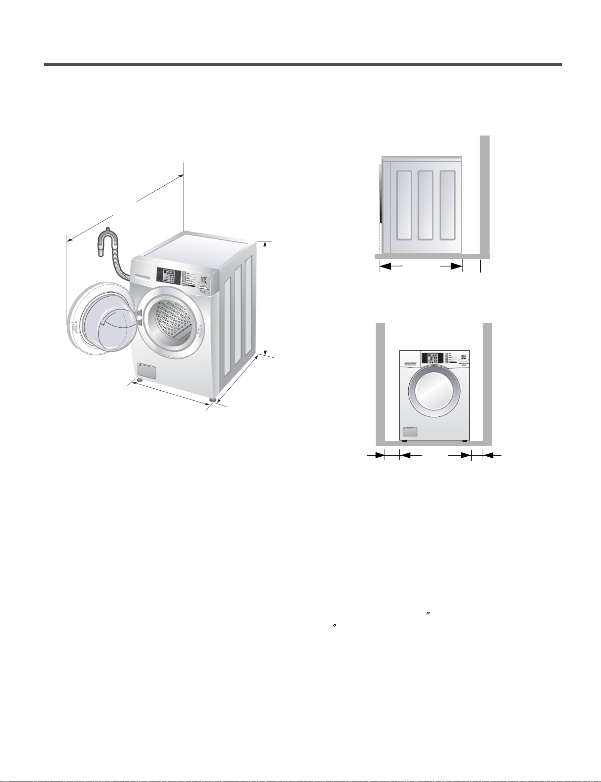
■ Installation clearances
The location must be large enough to open
the washer door completely.
■ Washer dimensions
The following dimensions shown are for the minimum
spacing allowed.
Additional spacing should be considered for
installation and servicing.
• Additional clearances might be required for wall,
door, and floor moldings.
• Additional spacing of 4 (10 cm) on back,
1 (2.5 cm) on all sides of the washer is
recommended to reduce noise transfer.
Companion appliance spacing should also be
considered.
■ Minimum installation spacing for
recessed area installation.
Front view
Side view
27"
(68.6 cm)
29
3
/
4
"
(75.6 cm)
38
11
/
16
"
(98.3 cm)
50
13
/
16
"
(129.1 cm)
29 3/4"
(75.6 cm)
4"
(10 cm)
27"
(68.6 cm)
1"
(2.5 cm)
1"
(2.5 cm)
Page 11
10
• Must be within 60 (1.5 m) of either side of the
washer. Do not overload the outlet with more
than one appliance.
• Time-delay fuse or circuit breaker is recommended.
NOTE: It is the personal responsibility and obligation
of the customer to have a proper outlet
installed by a qualified electrician.
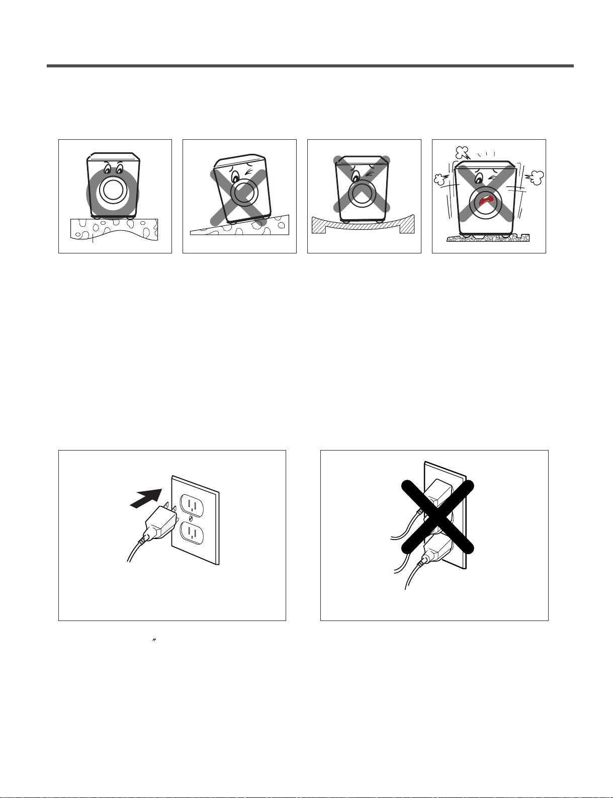
■ Level floor
• Allowable slope under entire washer is 1°.
• To minimize noise and vibration, the washer
MUST be installed on a solidly constructed
floor.
• Carpeting and soft tile surfaces are not
recommended.
• Never install the washer on a platform or
weakly supported structure.
NOTE: A firm, solid floor is even more critical to a
front-loading washer than to a top-loader.
If your floor is wood and/or frame
construction, you may need to reinforce it.
Front-loaders use substantially faster spin
speeds than top-loaders, causing greater
vibration. If the floor is not solid, your washer
will vibrate. You will hear and feel the
vibration throughout your house.
· Connect the power plug to the wall outlet. · Avoid connecting several electric devices, as
doing so may cause a fire.
■
CONNECT POWER PLUG
■
INST ALL THE APPLIANCE
ON A FLA T AND FIRM SURFACE
solid floor
Page 12
11
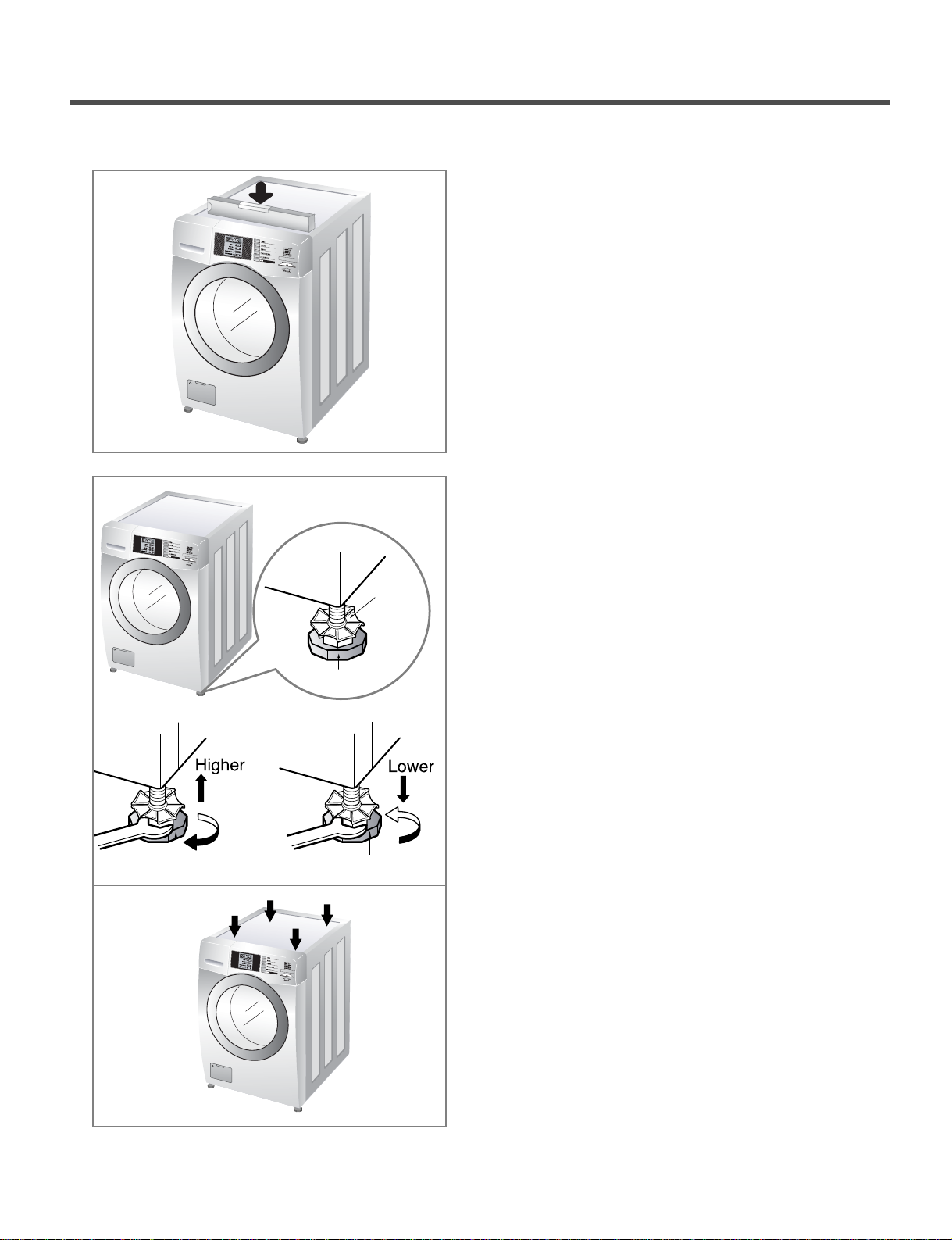
■ Level adjustment
• Leveling the washing machine properly prevents
excessive noise and vibration.
Install the appliance on a solid and level floor surface,
preferably in a corner of the room.
• If the floor is uneven, adjust the adjustable feet as
required. (Do not insert pieces of wood, etc. under
the feet.)
NOTE: Extend the feet no more than necessary to level
the washer. The more the feet are extended, the
more the washer will vibrate.
• Make sure that all four feet are stable and resting on
the floor and then check that the appliance is
perfectly level (Use a level).
• After the washer is level, tighten the lock nuts up
against of the base of the washer. All lock nuts must
be tightened.
• It is critical to adjust the feet perfectly. This must be
done while the washer is spinning with a load. Use
the wrench (supplied) to adjust the feet until there is
no vibration. Then tighten the lock nuts to prevent
further adjustment.
NOTE: If there is vibration and noise during the spin
cycle, re-check the leveling of the washer, adjust
the feet as required, and tighten the lock nuts
securely to prevent changes in adjustment.
Run the washer with a test load to make certain
your washer is properly leveled. Put an
unbalance weight part in the machine.
You can check noise and/or vibration on high
speed spin rpm through the QC test mode
(refer to page 18).
When the machine spins at high speed, verify
that it is stable. If not, adjust the feet
accordingly.
✽ Diagonal Check
When pushing down the edges of the washing machine
top plate diagonally, the machine should not move up
and down at all. (Please, check both directions.)
Lock nut
Adjustable feet
Adjustable feet Adjustable feet
Page 13
12
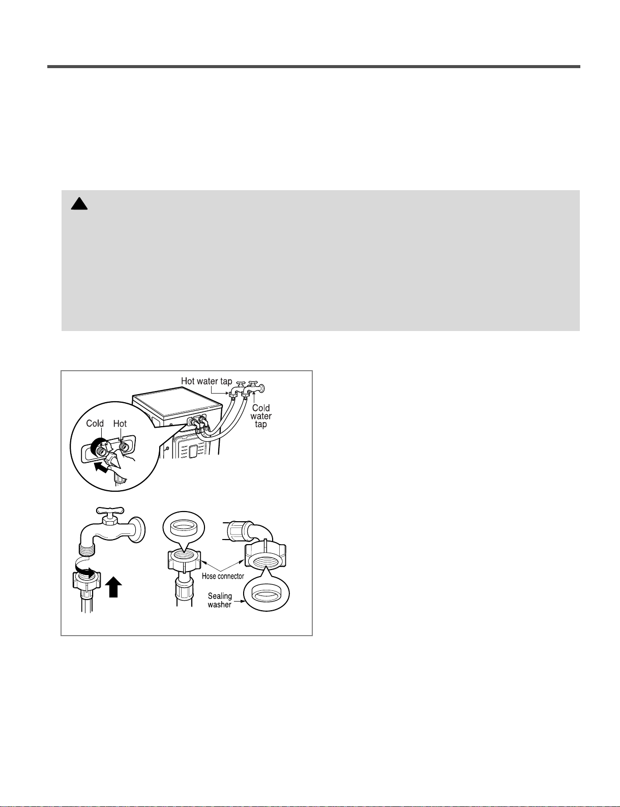
• Water supply pressure must be between
14.5 and 116 psi (100~800 kPa).
• Do not crossthread when connecting the inlet hose
to the valve.
• If the water supply pressure is more than 116 PSI,
a pressure reducing device should be installed.
• Two sealing washers are supplied with the water
inlet hoses to prevent water leaks.
• Check for leakage of washing machine connections
by turning the tap completely on.
• Periodically check the condition of the hose and
replace the hose if necessary.
• Make sure that there is no kink in the hose and that
it is not crushed.
• Be sure that the two water input ports are connected
to the correct water faucets. The connector for hot
water is colored red; the cold is blue.
■ Connecting the water supply hoses
NOTE: Use new hoses when installing a washing machine. Replace them periodically.
Old hoses should not be used.
■ Electrical connection
• Do not use an extension cord or double adapter.
• If the supply cord is damaged, it must be replaced by a qualified person in order to avoid a hazard.
• If the machine will not be used for an extended time, unplug it and shut off the water supply.
• Connect the machine to a grounded outlet in accordance with current wiring regulations.
• The appliance must be positioned so that the plug is easily accessible.
Do not install your washing machine in a room where temperatures below freezing may occur.
Frozen hoses may burst under pressure. The reliability of the electronic control unit may be impaired
at temperatures below the freezing point.
If the appliance is delivered in the winter months and temperatures are below freezing,
store the washing machine at room temperature for a few hours before putting it into operation.
!
WARNING! Concerning the power cord
Most appliances recommend they be placed upon a dedicated circuit; that is, a single outlet circuit which powers only that
appliance and has no additional outlets or branch circuits. Check the specification page of this owner's manual to be
certain.
Do not overload wall outlets. Overloaded wall outlets, loose or damaged wall outlets, extension cords, frayed power cords,
or damaged or cracked wire insulation are dangerous. Any of these conditions could result in electric shock or fire.
Periodically examine the cord of your appliance, and if its appearance indicates damage or deterioration, unplug it,
discontinue use of the appliance, and have the cord replaced with an exact replacement part by an authorized servicer.
Protect the power cord from physical or mechanical abuse, such as being twisted, kinked, pinched, closed in a door, or
walked upon. Pay particular attention to plugs, wall outlets, and the point where the cord exits the appliance.
Page 14

13
■ Installation of drain hose
• The drain hose should not be placed higher than
96 in. from the bottom of the washer.
• Properly securing the drain hose will protect the
floor from damage due to water leakage.
• Place the end of the drain hose in the hole of the
floor drain system.
• When installing the drain hose at a sink, secure it
so it cannot break away and cause flooding and
damage.
• Properly securing the drain hose will protect the
floor from damage due to water leakage.
· Make sure that the hose is not twisted.
· Avoid submerging the end of the hose.
Page 15

14
6. OPERATION
1 2
5 4 3
1 2
5 4 3
■ COIN TYPE (CW2079CWN )
■ CARD TYPE (CW2079CWD)
1. DISPLAY LED
2. CYCLE BUTTON
3. START BUTTON
4. STATUS LED
5. CYCLE LED
Page 16

15
The START LED flashes when the full vend price
has been satisfied and the cycle has been chosen.
33
START BUTTON
• LED flashes whenever the washing
cycle is in operation.
• LED flashes whenever the Rinsing
cycle is in operation.
• LED flashes whenever the Spining
cycle is in operation.
• LED flashes whenever the door lock
is activated.
44
STATUS LED
WHITES, COLORS, DELICATES, PERMANENT
PRESS or ADD SUPER WASH LED is lit for the
cycle is in operation.
55
CYCLE LED
The display shows the vend price and remaining time
and programming options. Error codes are also
displayed here.
11
Display LED
Press the CYCLE button to select the desired cycle
based on laundry types and conditions.
Use for hot washing for heavy fabrics, such as white
clothes, table linens, and heavily soiled clothes.
22
CYCLE BUTTON
WHITES
Use for warm washing for heavy fabrics, such as
jeans, corduroys, or work clothes.
COLORS
Use for cold washing for synthetic fabrics, such as
washable knit fabric and no-iron finishes.
DELICATES
Use for warm washing for sturdy fabrics, such as
work casual work.
PERMANENT PRESS
1 2
5 4 3
CYCLE LED STATUS LED START BUTTON
DISPLAY LED CYCLE BUTTON
Page 17

16
■ Select cycles designed for different types of fabric and soil levels.
CYCLE
Whites
Add super wash
- Adds an additional 5 minutes of washing time and an extra rinse
Cotton, Linen, Towels, Shirts,
Sheets
Hot/Cold High O
Colors
Mixed Loads, Work Clothes,
Jeans, Shirts
Warm/Cold High O
Delicates
Dress Shirts/Blouses,
Nylons, Sheer or Lacy Garment
Cold/Cold Low O
Perm Press
Dress Shirts/Pants, Wrinkle
Free Clothing, Poly/Cotton
Blend Clothing, Tablecloths.
Warm/Cold Medium O
Fabric type
Wash/Rinse
Temp.
Spin
Speed
Add Super
Wash
Page 18

17
7. WIRING DIAGRAM/PROGRAM CHART
Water Supply :W-S
Intermittent Spin :1 -S
Disentangle : D -T
Basic Cycle
Optional Cycle
SPIN
10min
WASH
10min
RINSE
16min
60 * 60
1806018060180
60 60 60
180
60 * 60
60
~
Approx.
Working
Time
(min)
1 2 3 4 5 6 7 8
9
10 11 12 13 14 15 16 17
W
-
S
W A S H
D R A I N
1
/
S
W
/
S
R I N S E
D R A I N
W
/
S
R I N S E
D R A I N
W
/
S
R I N S E
D R A IN
S P I N
D
/
T
E N D
INITIAL STAGE
1
NORMAL
SUPER
CYCLE
2 3
WHITE
COLOR
PERM PRESS
DELICATES
37
37
35
35
C Y C L E
S T E P
C
O
U
R
S
E
Time
(sec)
10
10
6
8
1
/
S
1809180
8
1
/
S
360
-
660
360
-
660
360
-
660
360
-
660
■ Card T ype (CW2079CWD) ■ Coin Type (CW2079CWN)
■ Pogram Chart
Page 19

18
8. TROUBLESHOOTING
8-1. BEFORE PERFORMING SERVICE
■ Be careful of electric shock when disconnecting parts while troubleshooting.
■ The voltage of each terminal is 120V~ when the unit is plugged in.
8-2. QC TEST MODE.
The washer must be empty.
■ Card Type
1. Insert Service Card
2. Display
3. Press the Start button repeatedly to cycle through the test modes.
■ Coin Type
1. Open the Service Door
2. Display
3. Press the Start button repeatedly to cycle through the test modes.
Number of times the
START button is pressed
Check Point
None
1time
2 times
3 times
4 times
5 times
6 times
7 times
8 times
9 times
10 times
11 times
12 times
13 times
14 times
15 times
Turns on all lamps and locks the door
Tumble Clockwise.
Low Speed Spin
High Speed Spin
Inlet valve for main water turns on.
Inlet valve for hot wash turns on.
Inlet valve for softener turns on.
Inlet valve for bleach turns on.
Tumble counter clockwise.
Drain Pump turns on
Turns on all lamps.
Button Checks.
High Speed Spin
Displayed 1F81 and ES XX alternately. - XX
(Version)
rpm (40~50)
rpm (600)
rpm (1000)
Water level frequency (261~)
Water level frequency (261~)
Water level frequency (261~)
Water level frequency (261~)
rpm (40~50)
Water level frequency (261~)
Displayed 1F81 and ES XX alternately.
Displayed 1F81 and ES XX alternately.
rpm (1000)
Display
8-3. HOW TO CHECK THE WATER LEVEL FREQUENCY
■ Press and hold the ADD SUPER WASH and PERMANENT PRESS buttons simultaneously.
When you check the water level, the first digit is a 0 which means 2.
A display indicating 041 is a water level frequency of 241 multiplied by 0.1 KHz , for an
actual frequency of 24.1 KHz.
8-4. HOW TO CHECK THE RPM
■ Press the ADD SUPER WASH AND WHITES button simultaneously.
Under 200 rpm: The display indicates the rpm. (Under 200 rpm)
Over 200 rpm: The display indicates the rpm. (x 10 rpm)
So, for example a display indicating 050 : rpm of 050 x 10 rpm = 500rpm
Page 20

19
8-5. ERROR DISPLAY
• If you press the ST AR T button when an error is displayed, any error except will disappear and the
machine will go into the pause status.
ERROR SYMPTOM CAUSE
WATER INLET
ERROR
• Correct water level (246) is not reached within 3 minutes
after water is supplied or it does not reach the preset water
level within 12 minutes.
• The load is too small.
• The appliance is tilted.
• Laundry is gathered to one side.
• Non distributable things are put into the drum.
1
2
IMBALANCE
ERROR
• Not fully drained within 3 minutes.
3
DRAIN
ERROR
• Water is overflowing (water level frequency is over 213).
※ If is displayed, the drain pump will operate to
drain the water automatically.
4
OVER FLOW
ERROR
• The SENSOR SWITCH ASSEMBLY is out of order.
5
PRESSURE
SENSOR
ERROR
• Door not all the way closed.
• Loose electrical connections at door switch and
PWB Assembly.
• The DOOR SWITCH ASSEMBLY is out of order.
6
DOOR OPEN
ERROR
Page 21

20
ERROR SYMPTOM CAUSE
• The connector (3-pin, male, white) in the MOTOR
HARNESS is not connected to the connector
(3-pin, female, white) of STATOR ASSEMBLY.
• The electric contact between the connectors
(3-pin, male, white) in the MOTOR HARNESS
and 4-pin, female, white connector in the MAIN PWB
ASSEMBLY is bad or unstable.
• The MOTOR HARNESS between the STATOR
ASSEMBLY and MAIN PWB ASSEMBLY is cut (open
circuit).
• The hall sensor is out of order/defective.
7
LOCKED
MOTOR
ERROR
• Loose Ball Sensor Connector.
• Ball Sensor is out of order.
※ Displayed only when the START button is first pressed
in the QC Test Mode.
8
BALL SENSOR
ERROR
•
Disconnection of Card Reader Wire.
10
CARD
READER
ERRER
• EEPROM is out of order.
※ Displayed only when the START button is first pressed
in the QC Test Mode.
9
EEPROM
ERROR
Page 22

21
9. DIAGNOSIS AND TROUBLESHOOTING
1. Be careful of electric shock if disconnecting parts while troubleshooting.
2. First, check the connection of each electrical terminal with the wiring diagram.
3. If you replace the MAIN PWB ASSEMBLY, reinsert the connectors correctly.
NO
YES
YES
YES
YES
NO
NO
NO
NO
YES
PWB ASSEMBLE, DISPLAY
5 5
5
5
1
3
4
Is the supplied voltage 120 V AC?
Is the voltage between the FILTER ASSEMBLY
connectors
and 120 V AC?
Is the LED lamp on?
Are the connectors
on the PWB loose?
Is wire of the DISPLAY PWB ASSEMBLY
broken?
Replace DISPLAY PWB ASSEMBLY
or repair wire.
Check the fuse or reset
the circuit breaker.
Replace the FILTER
ASSEMBLY (CIRC).
Replace MAIN PWB
ASSEMBLY.
Reconnect.
Replace the CABLE
(HARNESS)
NO POWER
WARNING
!
Page 23

22
NO
YES
YES
NO
YES
NO
YES
NO
NO
YES
NO
Main washer
Safterner
Is the tap opened?
Is the tap frozen?
Is the water supply shut-off?
Is filter in the inlet valve clogged with
foreign material?
Open the tap.
After separating the hose
from the washing machine
soak in hot water for 10
minutes.
Is resistance between each terminal of the INLET
V ALVE ASSEMBLY 0.8-1.2
kΩ
?
Verify the voltage of the inlet valve connector is
120 V AC.
Refer to page 18, QC TEST MODE.
Replace the INLET
V ALVE ASSEMBLY.
※Make sure the tap is closed before
replacing.
Check electrical connection.
Replace the MAIN PWB
ASSEMBL Y.
IE ERROR (NO WATER SUPPLY)
Clean the filter of
INLET V ALVE ASSEMBLY
Page 24

23
NO
YES
YES
NO
NO
NO
NO
YES
YES
NO
12
34
(Yellow 4pin)
Repair the DRAIN HOSE
ASSEMBL Y.
Reconnect or repair the
connector
Replace the DRAIN
PUMP ASSEMBL Y.
Replace the MAIN PWB
ASSEMBL Y.
Is the drain hose twisted or frozen?
Is the connector disconnected or disassembled?
Is the coil of the drain pump too high or low?
(resistance of the coil is 10-20 Ω)
When checking voltage between connectors
(
and ) during drain, is the voltage 120 V AC
as in the figure?
OE ERROR (DRAIN TROUBLE)
Page 25

24
YES
YES
YES
NO
NO
YES
NO
Main washer
softener
Hose
PRESSURE S/W ASSEMBLY
YES
Hose
PRESSURE S/W ASSEMBLY
YES
NO
Replace the INLET
V ALVE ASSEMBLY.
※Make sure the tap is closed
before replacing.
Replace the
PRESSURE S/W
ASSEMBL Y.
Replace the
PRESSURE S/W
ASSEMBL Y.
Is resistance between each terminal of INLET
V ALVE ASSEMBLY 0.8~1.2kΩ?
Is water continuously supplied?
Is PRESSURE S/W ASSEMBL Y broken?
Check electrical connection.
Replace the MAIN PWB ASSEMBL Y.
Is PRESSURE S/W ASSEMBL Y broken?
Check electrical connection.
Replace the MAIN PWB ASSEMBL Y.
FE ERROR
PE ERROR (
PRESSURE S/W TROUBLE)
Page 26

25
YES
NO
NO
YES
DOOR S/W
ASSEMBLY
dE ERROR (DOOR ERROR)
Was the load too large?
Is DOOR SWITCH ASSEMBLY broken?
Does the spring of Latch Hook actuate?
Check the DOOR SWITCH
ASSEMBLY Connector and
MAIN PWB ASSEMBLY
(Blue 4 pin , Yellow 4 pin
and white 3 pin connector .
Replace the DOOR
SWITCH ASSEMBLY.
Replace Door Assembly.
1
3
2
Page 27

26
YES
YES
YES
NO
NO
Base Packing
Level
Have all the transit bolts and base packing
been removed?
Remove the transit bolts
and Base packing.
Move the washer or
reinforce the floor.
Is the washer installed on a solidly constructed
floor?
Check if the washer is perfectly level as follows:
Check the leveling of the washer with a level
and check that the washer is stable.
Put an unbalance part (rubber) inside of drum
and start QC test mode and run in high spin
(Refer to page 17)
When the machine is spinning in high speed,
verify that it is stable.
VIBRATION & NOISE IN SPIN
If it is not stable, adjust feet accordingly. After
the washer is level, tighten the lock nuts up
against of the base of the washer. All lock nuts
must be tightened.
If you do not have the unbalance part, put 4.5 to
6.5 lbs (2 to 3 kg) of clothing.
When the machine is spinning at high speed,
verify that it is stable.
Page 28

27
YES
YES
YES
NO
NO
NO
YES
DRAWER
DRAWER
CAP
Is water supplied?
Are the plugs correctly connected to the terminals
of the INLET V ALVE ASSEMBLY?
Is detergent/softener/bleach put in the correct
compartment of the DRAWER?
Is the detergent/softener/bleach CAP clogged?
Refer to page 22
IE ERROR
Check the wiring.
Put it in the correct
compartment
Clean the CAP and
DRAWER
DETERGENT/SOFTENER/BLEACH DOES NOT FLOW IN
ABNORMAL SOUND
Secure the bolt.
Replace the ST ATOR
ASSEMBL Y or ROTOR
ASSEMBL Y.
Is the motor bolt loose?
Is there friction noise coming from the motor?
Page 29

28
YES
YES
SUDS OVERFLOW FROM THE APPLIANCE
Is HE(High Efficiency) detergent used?
Is the proper amount of detergent used
as recommended?
Recommend to reduce the amount
of detergent.
This appliance has an automatic suds sensing function which
prevents overflow.
When excessive suds are sensed, the suds removing
implementations such as drain, water input, and pause will
operate, without rotating the drum
Page 30

29
10. DISASSEMBLY INSTRUCTIONS
DISPLAY PWB ASSEMBLY
CONTROLPANELASSEMBLY
DISPLAYPWBASSEMBLY
✽ Be sure to unplug the machine before disassembling and repairing the parts.
1. Pull out the DRAWER.
Do not pull out the DRAWER too forcefully as it
can be broken.
2. Unscrew 3 screws
3. Disassemble the CONTROL P ANEL ASSEMBLY
- Pull out the CONTROL P ANEL .
Do not pull out the CONTROL P ANEL too
forcefully as it can be broken.
4. Disconnect the DISPLA Y PWB ASSEMBLY
connector from CABLE (HARNESS).
1. Disassemble the CONTROL P ANEL ASSEMBLY
(refer to page 28)
2. Unscrew the 4 screws from the CONTROL PANEL
ASSEMBL Y.
3. Disassemble the DISPLA Y PWB ASSEMBLY.
⇩
DRAWER
CONTROL PANEL
ASSEMBLY
CONTROL PANEL
ASSEMBLY
Page 31

30
TOP PLATE ASSEMBLY
1. Disassemble the CONTROL P ANEL ASSEMBLY
(refer to page 29)
2.
Remove 2 screws on the
CONTROL P ANEL
frame.
3.
Push the TOP PLATE backward forcefully.
4.
Lift the TOP PLATE.
Page 32

31
1. Disassemble the CONTROL P ANEL ASSEMBLY
(refer to page 29).
2. Disassemble the
TOP PLATE
ASSEMBL Y
(refer to page 30).
3. Unscrew a screw on PRESSURE SWITCH
ASSEMBL Y
4. Remove all wire from hooks.
5. Remove the Protective Cover.
6. Disconnect the connectors.
7. Unscrew 1 screw on the back.
8. Disassemble the MAIN PWB ASSEMBL Y.
CONNECTOR
PROTECT COVER
MAINPWBASSEMBLY
Page 33

32
1. Disassemble the CONTROL P ANEL ASSEMBLY
(refer to page 29).
2. Disassemble the
TOP PLATE
ASSEMBL Y
(refer to page 30).
3. Disassemble the clamps and hoses.
4.
Disassemble the bellows at the lower side of DISPENSER
1. Disassemble the CONTROL P ANEL ASSEMBLY
(refer to page 29).
2. Disassemble the
TOP PLATE
ASSEMBL Y
(refer to page 30).
3.
Disassemble the 4 connectors from the VALVES.
4. Disassemble the clamps and hoses.
5. Unscrew the 2 screws in the back.
Connector Color
①①
Blue Housing (OR-BK)
②②
White Housing (WH-BK)
③③
Blue Housing (GY -BK)
④④
Red Housing (BL-BK)
DISPENSER ASSEMBL Y
Clamp
DISPENSERASSEMBLY
INLETVALVEASSEMBLY
Page 34

33
1. Disassemble the CONTROL P ANEL ASSEMBLY
(refer to page 29).
2. Open the DOOR.
3. Disassemble the CLAMP ASSEMBL Y.
4. Unscrew the 4 screws from the upper part of the
CABINET COVER.
5. Unscrew the screw from CAP COVER.
6. Unscrew the screw from inside CAP COVER.
7. Put a flat (
-
) screwdriver or putty knife into both sides
of the CAP COVER, and pull it out.
3
CAP COVER
CABINETCOVER
Page 35

34
9. Tilt the CABINET COVER.
10. Disconnect the DOOR S/W connector.
※※
NOTE: When assembling the CABINET
COVER, connect the connector.
1 1. Lift and separate the CABINET COVER.
8. Unscrew the screw from the lower side of the CABINET
COVER.
1. Disassemble the CABINET COVER
(refer to page 32).
2. Disassemble the CLAMP ASSEMBL Y.
3. Disassemble the GASKET.
TUB GASKET
CLAMP
GASKET
Page 36

35
1. Open the DOOR.
2. Unscrew the 7 screws from the HINGE COVER.
3. Put a flat ( - ) screwdriver into the openng of the hinge, and
pull out the HINGE COVER.
4. Unscrew a screw from the lower side of DOOR.
5. Lift door and remove.
DOORASSEMBLY
1. Open the DOOR and disassemble the CLAMP
ASSEMBL Y.
2. Unscrew the 2 screws.
3. Remove connector from DOOR S/W ASSEMBLY.
DOOR SWITCH
ASSEMBLY
CLAMP
ASSEMBLY
DOORLOCKSWITCHASSEMBLY
※※
Be careful! The door is heavy .
※※
NOTE
• Reconnect the connector after replacing the
DOOR SWITCH ASSEMBL Y.
HINGE COVER
Page 37

36
PUMP ASSEMBLY
THERMISTOR
1. Disassemble the CABINET COVER
(refer to page 33).
2.
Separate the PUMP HOSE and the BELLOWS
from the PUMP ASSEMBLY.
3. Unscrew 2 screws.
4.
Remove the PUMP ASSEMBLY in arrow
direction.
1. Disassemble the CABINET COVER
(refer to page 33).
2.
Unplug the white connector from the THERMISTOR.
3.
Pull it out by holding the bracket of the THERMISTOR.
1. Disassemble the CONTROL P ANEL ASSEMBLY
(refer to page 29).
2. Disassemble the
TOP PLATE
ASSEMBL Y
(refer to page 30).
3. Disassemble two (or three) connectors from
the NOISE FILTER.
4. Unscrew a screw from the TOP BRACKET.
NOISE FILTER
NOISEFILTER
Page 38

37
BACK COVER
SENSOR ASSEMBLY(BALL SENSOR)
1.
Unscrew the 4 screws from the BACK COVER.
2.
Unscrew a screw from the lower-right side of the
CABINET.
3.
Disconnect the connector from PWB HARNESS.
Page 39

38
ROTOR
MOTOR ASSEMBLY
DAMPER
1.
Disassemble the BACK COVER.
2.
Remove the bolt.
3.
Pull out the ROTOR.
4.
Unscrew the 2 screws from the tub bracket.
5.
Remove the 6 bolts on the stator.
6.
Unplug the 2 connectors from the STATOR.
1.
Disassemble the CABINET COVER or BACK COVER.
2.
Disassemble the damper hinges from the tub
and base.
3.
Separate the dampers.
※※
NOTE
• Do not re-use an old damper pin. Always
replace it with a new one.
STATOR
Page 40

39
11. EXPLODED VIEW
11-1. CABINET & CONTROL P ANEL ASSEMBLY
A105
A201
A155
A440
A430
A100
A101
A104
A102
F110
F210
A485
A455
A450
A110
A150
A154
A131
A390
A153
A151
A130
A140
A133
A310
A300
A303
A200
A141
A410
A152
A103
A490
A220
A495
Page 41

40
11-2.
DRUM & TUB ASSEMBLY
K344K346
K123
K143
K360K351
F140
K411
K410
K110
K140
K310
K510
K111
K350
K115
K340
K342
K131
K311
F315
F465
K125
F466
F467
K550
F463
K130
K530
F464
K121
K122
K610
K611
K141
F145
K520
F461
K540
F468
K105
K135
Page 42

41
11-3.
DISPENSER ASSEMBLY
˚
HOT (RED)
COLD (BLUE)
F324
F462
F300
F226
F220
F440
F436
F431
F430
F160
F170
F441
F435
F120
F130
F432
A275
A276
F321
F326
F323
 Loading...