

Page 1

CD-ROM DRIVE
MODEL : CRD-8520B/CRD-8521B
OWNER’S MANUAL
BEDIENUNGSHANDBUCH
MODE D’EMPLOI
MANUALE D’USO
MANUAL DE USUARIO
To enjoy fully all the features and functions of your CD-ROM Drive,
Please read this Owner’s Manual carefully and completely.
Questo manuale include il tagliando
di garanzia. (pagina n. I-8)
website ; http://www.LGEservice.com
e-mail ; http://www.LGEservice.com/techsup.html
Page 2
CAUTION : The laser used in the CD-ROM drive can damage your eyes.
Do not attempt to open the cover.
To reduce the risk of electric shock, do not remove cover (or back).
No user-serviceable parts inside.
Refer servicing to qualified service personnel.
This unit uses CD-ROM discs
marked with this symbol :
English
Use of controls or performance of procedures other than those specified here in may result in hazardous radiation
exposure.
PRODUCT COMPLIES WITH DHHS
RULES 21 C.F.R. SUB-CHAPTER J,
IN EFFECT AT THE DATE OF MANUFACTURE.
WARNING : To reduce the risk of fire or electric shock,
do not expose this appliance to rain or moisture.
Industry Canada requirement
This class B digital apparatus meets all requirements of the Canadian Interference-Causing Equipment
Regulations.
Cet appareil numérique de la classe B respecte toutes les exigences du Règlement sur le matériel brouilleur du
Canada.
FCC COMPLIANCE STATEMENT
Note : This equipment has been tested and found to comply with the limits for a Class B digital device, pursuant to Part 15 of
the FCC Rules.
These limits are designed to provide reasonable protection against harmful interference in a residential installation.
This equipment generates, uses, and can radiate radio frequency energy and, if not installed and used in accordance with the instructions, may cause harmful interference to radio communications. However, there is no guarantee
that interference will not occur in a particular installation. If this equipment does cause harmful interference to radio
or television reception, which can be determined by turning the equipment off and on, the user is encouraged to try
to correct the interference by one or more of the
following measures:
- Reorient or relocate the receiving antenna.
- Increase the separation between the equipment and receiver.
- Connect the equipment into an outlet on a circuit different from that to which the receiver is connected.
- Consult the dealer or an Authorized Service Center for help.
• FCC WARNING
Changes or modifications not expressly approved by the party responsible for compliance could void the user’s authority
to operate the equipment.
• This CD-ROM Drive is for use only with UL listed personal computers that have installation instructions
detailing user installation of card cage accessory.
This product is manufactured to comply with the radio interference requirements of EEC DIRECTIVE
89/336/EEC, 93/68/EEC and 73/23/EEC.
E-2
Page 3
DECLARATION OF CONFORMITY
This device complies with Part 15 of the FCC Rules. Operation
is subject to the following two conditions : (1) this device may
not cause harmful interference, and (2) this device must accept
any interference received, including interference that may cause
undesired operation.
Trade Name/Model : LG or Goldstar/CRD-8520B or CRD-8521B
Responsible Party : LG Electronics U.S.A. Inc., Chicago office
Address : 6133 North River RD Suite 1100
Rosemont, IL. 60018, U.S.A.
Contact Person: Mr. P. H. Byun, General Manager
Tel. No. (847) 993-4529
Equipment Classification : FCC Class B Peripheral Device(JBP)
Type of Product (EUT) : CD-ROM Drive
Manufacturer: LG Electronics lnc.
Address: 19-1, Cheongho-Ri, Jinwuy-Myon
Pyungtaek-Shi, kyunggi-Do, 451-713 Korea
Attention: Mr. T.K.Lee - General Manager
Multimedia Standards Team
We hereby declare that the equipment bearing the trade and model
number specified above was tested conforming to the applicable FCC
Rules under the most accurate measurement standards possible, and
that all the necessary steps have been taken and are in force to assure
that production units of the same equipment will continue to comply
with the Commission’s requirements.
E-3
Page 4

Features
Features
[ E-IDE interface
[ 52X-speed Max 7800KB/sec data transfer rate
[ 80ms random access time
[ Intelligent 128KB data buffering system
[ Small CPU bandwidth (MPC spec.)
[ Motorized tray loading system
[ Horizontal/Vertical mounting support
[ Designed for internal mounting
[ Emergency eject support
[ Easy audio CD control button support
[ Supports Windows 95, 98 & 2000 Plug-and-Play ATAPI protocol
[ Multimedia PC MPC compliant
[ Photo CD multisession support
System Requirement*
[ IBM PC AT or compatible, 486 SX 25 processor or higher
(Pentium 133 Processor or higher recommended).
[ 640 Kb memor y (16Mb or higher recommended).
1
”
internal drive bay.
[ A suitable free standard 5
[ MS-DOS version 3.1 or higher. (Windows 95 and above recommended).
1
”
1.44 Mb Floppy Drive.
/
[ 3
2
[ An existing IDE controller with an available cable connector or a new IDE
controller (recommended with IDE PIO Mode 4 capability) that you will need
to install.
/
4
* Please note: certain software (i.e. particularly those including Video
playback) may require an considerably increased specification PC to give
acceptable results.
E-4
Page 5
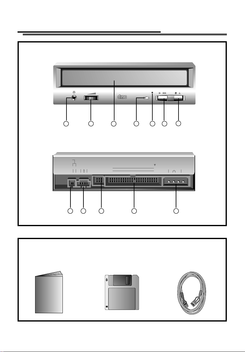
Location and Function of Controls
Front View
COMPACT
1
2
Back View
DIGITAL
ANALOG
AUDIO
AUDIO
D G R G L
1 2 3 4 5
Supplied Accessories
zz
Owner’s Manual
zz
4
INTERFACE POWER
C S M
S L A
3
39
40
Device Driver(MS-DOS)
5 6
1
2
7
+ 5 GND +12
zz
Audio Cable
E-5
Page 6

Front View
1. Headphone Jack
Standard
2. Headphone Volume Control
Adjusts the headphone sound level.
3. Disc Drawer
Accepts a CD-ROM disc on its tray.
4. Busy Indicator
The Busy Indicator lights during initialization and data-read operations.
5. Emergency Eject Hole
Insert a paper clip here to eject the drawer manually or when there is no
power.
6. Play/Skip Button
When an Audio CD is in the Disc Drawer, pressing this button will start
playing audio CDs from the first track. If an audio CD is playing, pressing this
button will skip to the next track.
7. Open/Close/Stop Button
This button is pressed to open or close the CD tray.
If an audio CD is playing, pressing this button will stop it, and pressing it
again will open the tray.
1
/8” (3.5mm) stereo jack for listening to the audio signal from audio CDs.
Back View
1. Digital Audio Output Connector
This is a digital audio output or Video CD output connector.
You can connect this to a digital audio system or a Video CD Board.
2. Analog Audio Output Connector
The Audio Output Connector connects to a sound card.
3. Master/Slave/CSEL Jumper
These three jumpers are used to set the CD-ROM Drive to either a Master,
Slave, or CSEL device.
4. Interface Connector
This 40-pin connector is used to transfer data and control signals between the CDROM Drive and your PC.
5. Power-in Connector
Attach a power cable from the computer to this connector.
E-6
Page 7

Installing the Drive
Before installing the drive, turn off the system power. Follow the steps below to
install the CD-ROM drive:
1. Remove the cover from your computer system. Refer to manual for the
computer for details about removing the cover.
2. Insert the CD-ROM drive unit into a free 5.25-inch drive bay. Secure the
CD-ROM drive to the drive bay rails with the mounting screws (supplied).
3. Connect the 4-pin power cable and 40-pin IDE interface cable to the back of
the CD-ROM drive.
POWER
2
1
+
D
N
G
5
A
IT
IG
D
IO
D
U
A
Audio Cable
G
O
L
A
N
A
L
IO
D
U
A
S
C
L
G
R
G
D
L
S
INTERFACE
9
3
M
0
4
A
+
1
2
Power Cable
IDE cable
Red Strip
Notes: If there is no spare power cable available in the computer, you will have
to purchase a splitter cable of a suitable type.
The red edge of the IDE cable corresponds to pin 1 of the IDE interface on the
CD-ROM drive.
Please Note: an IDE cable is not supplied and may be required to be purchased
separately.
If the computer is using a sound card, the drive is connected to the sound card
with an audio cable. This CD-ROM drive is supplied with a Creative Labs
SoundBlaster© compatible audio lead, if this is not suitable for your sound card,
it maybe necessary for you to purchase a suitable lead from your retailer. Refer
to the manual for the sound card for detailed information regarding connection.
E-7
Page 8

4. Adjust the Master/Slave jumpers on the back of the CD-ROM drive as
necessary.
Connect the CD-ROM drive to the IDE ports of your motherboard. In general,
the hard drive will be in Primary IDE port and Master device for booting the
operating system. There are two possible alternate connection for CD-ROM
drive installation.
A) When using a Primary IDE por t
If you need to connect your CD-ROM drive to the same Primary IDE port, the
CD-ROM drive should be set to Slave position.
Master drive
(Booting hard disk)
D
I
G
I
T
A
L
A
A
N
U
A
D
L
O
I
O
G
A
U
D
I
O
D
G
R
G
L
INTER
C
S
M
FA
CE
3
9
4
0
PO
W
ER
1
+
5
G
N
D
+
1
2
2
Primary connector
Slave drive
(CD-ROM drive)
B) When using a Secondary IDE por t
You can also connect CD-ROM drive to the Secondary IDE port and set to
Master position.
Master drive
(Booting hard disk)
D
I
G
I
T
A
L
A
A
N
U
A
D
L
O
I
O
G
A
U
D
I
O
D
G
R
G
L
I
C
N
S M
T
E
R
F
A
C
3
E
9
40
P
O
W
E
R
1
+5
G
N
D
+1
2
2
D
I
G
I
T
A
L
A
A
N
U
A
D
L
O
I
O
G
A
U
D
I
O
D
G
R
G
L
I
C
N
S
T
M
E
R
F
A
C
E
3
9
4
0
P
O
W
E
R
1
+
5
GN
D
+1
2
2
Master drive
(CD-ROM drive)
Slave drive
(Other IDE drive)
Motherboard
Primary connector
Secondary connector
5. When the installation of the drive unit is complete, replace the computer
cover.
6. Reconnect the computer power cord and turn on the computer.
E-8
Page 9

Device Drivers
When using Windows 95/98/2000 or Window NT Workstation Ver. 4.0, the
installation of any software driver or special device is not required.
1
This CD-ROM drive is supplied with MS-DOS drivers on a 3
These drivers are required to use the CD-ROM drive in DOS and Windows 3.1.
Drivers for other Operating Systems are not normally required or available as
they usually have an generic IDE, E-IDE/ATAPI CD-ROM driver built in; Windows
95, 98, 2000, NT 3.51 and higher and OS/2 Warp 3.0 are such examples.
If it is necessary to edit any file manually, first make a backup copy on a floppy
disk, then edit the original file, save it to your hard drive, exit, and re-boot the
PC to ensure the change will be implemented.
Running the Install Program (MS-DOS Installation)
1. Boot to the DOS prompt.
2. Insert the driver diskette into the appropriate drive.
3. Go to the floppy drive by typing A: or B: at the DOS prompt, as appropriate.
4. Type the word INSTALL and [Enter].
5. The Install program will begin lodaing and you will prompted to accept the default
directory of C:\DVDROM press [Enter] to accept (suggested) or edit the path then
press [Enter].
6. When installation is complete, remove the diskette and reboot your PC.
(Note: You must have a Config.sys and an Autoexec.bat file on your hard drive
for the install program to add the necessary command lines.)
/2-inch floppy disk.
For Windows 98/95 Users
In order to ensure normal drive operation, please check the following:
[
• The drive is displayed in
[control panels]-[system]-[device manager]-[CD-ROM]
• 32-bit is displayed in
[control panels]-[system]-[performance]
If the drive is not recognized by your computer, please check the following
[
items.
• If a indicator is displayed on the IDE controller in [control panels]-
[system]-[device manager]-[harddisk controller], you will need to contact
your PC’s manufacturer or the motherboard’s manufacturer and get the appropriate IDE controller driver.
Run ADD NEW HARDWARE in Control Panel to let PC search again for new
[
device.
E-9
Page 10

For Windows NT Workstation Ver. 4.0 Users
In order to ensure normal drive operation, please check the following:
[
• The drive is displayed on the IDE controller in
[control panels] - [SCSI adapter] - [devices]
If the drive is not recognized by your computer, please check the following
[
items.
• If a indicator is displayed on the IDE controller in [control panels]-
[SCSI adapter]-[devices], you will need to contact your PC’s manufacturer
or the motherboard’s manufacturer and get the appropriate IDE controller
driver.
Emergency Eject
This drive has a function that allows the CD to be ejected manually if this
becomes necessary in an emergency, such as failure of the drive or a power
outage. Follow this procedure in such a case.
NOTE: Don’t use this feature except in an emergency.
1) Turn the power to OFF.
2) Poke a fine-tipped object (such as a straightened heavy duty paper clip) into
the small hole at the front. The front door will pop open and the disk tray will come
partway out.
3) Pull the front door to open it all the way, then grip the disc tray between
thumb and forefinger and gently pull it straight out.
NOTE: This feature is a last measure to be used only in an emergency. Using it
excessively will cause malfunction.
E-10
Page 11

Installation, Usage and Handling Precautions
lnstallation
[
Avoid placing the drive in a location subject to :
- high humidity
- high temperature
- mechanical vibration
- direct sunlight
Operation
[
- During operation, excessive vibration or a sudden jolt to the drive may
cause a malfunction.
- Avoid exposing the drive to sudden changes in temperature. This may
cause condensation to collect inside the drive.
- Do not use damaged, cracked, or warped discs.
Transportation
[
- Always remove the disc before moving the drive.
Troubleshooting
* When the CD-ROM drive does not work with the hard disk drive in primary
IDE channel.
(SOLUTION)
1. Check the CD-ROM drive Master/Slave Jumper setting.
The CD-ROM drive must be set to the Slave mode.
2. Check to be sure your hard disk Interface type is IDE type.
3. Check your hard disk Master/Slave Jumper setting.
Some old-version IDE type hard disks were set to Master Only mode.
In that case, contact your hard disk company and change your hard disk
jumper setting to master mode.
4. If the CD-ROM drive does not work with above methods, you may need a
secondary IDE card. If you use the secondar y IDE card, you should set the
CD-ROM drive jumper to the master mode if the CD-ROM drive is the first
device you are connecting to the secondary IDE card.
* When the CD-ROM drive does not install in OS/2 warp.
(SOLUTION)
1. Select NON-LISTED IDE CD.
* CD-ROM drive is not present in Windows 3.1 or 3.11 or DOSSHELL.
(SOLUTION)
1. When the WIN or DOSSHELL command lines are present in your
AUTOEXEC.BAT, make sure that the MSCDEX.EXE command line appears
before the WIN or the DOSSHELL command lines.
NOTE: For more information, consult the README.TXT file of the supplied Setup
Diskette.
E-11
Page 12

Specifications
General
Data Capacity
Disc Diameter
Rotational Speed
Performance
Interface
Supported System
Transfer rate
Access Time
MTBF
Buffer size
Error Rate
ECC on
ECC off
User Data/Block
Supported Disc
Audio Specifications
Frequency Response
S / N Ratio
THD
Channel Separation
Headphone Level
Line Output Level
Line Output Jack
Headphone Jack
553 Mbytes (mode 1), 635 Mbytes (mode 2)
12 cm/8 cm
Approx. 10,800 rpm (inner max speed)
E-IDE
IBM PC-AT or Compatible
Sustained Data Transfer Rate=Max 7,800Kbytes/sec
Random 80 ms Typical
125,000 Power On Hours (Duty Cycle 10%)
128 Kbytes
15
1 block/10
1 block/10
2,048 bytes/block (Mode1 & Mode2 Form1)
2,340, 2,336 bytes/block (Mode2)
2,324 bytes/block (Mode2 Form2)
2,352 bytes/block (CD-DA)
CD-DA, CD-ROM, CD-ROM XA-READY, Photo-CD
CD-Plus/CD-Extra, Mixed CD, CD-RW
20 Hz - 20 KHz ±3 dB
75 dB
0.05 % at 1 KHz
75 dB at 1 KHz
0.60 Vrms (33Ω)
0.70 Vrms ± 20% (47kΩ)
4-Pin terminal (Rear)
ø 3.5 mm (Front)
bits (52x)
12
bits (52x)
Environment
Temperature
5 - 45 °C
Power Requirements
12 V ± 5%
Ripple < 100m Vpp
5 V ± 5%
Ripple < 100m Vpp
NOTE: Specifications are subject to change without notice for improvement.
1.5A (Maximum)
0.9A (Maximum)
E-12
Page 13

*
Page 14

CD-ROM DRIVE
English
Deutsch
Français
Italiano
E
N
H
A
C
E
D
CH01
CLASS 1 LASER PRODUCT
KLASSE 1 LASER PRODUKT
LUOKAN 1 LASER LAITE
KLASS 1 LASER APPARAT
Copyright©2000 LG Electronics Inc.
Spanish
LG Electronics U.S.A. Inc.
1000 Sylvan Ave. Englewood Cliffs
NJ 07632 U.S.A.
LG Electronics Canada lnc.
235 Superior Blvd, Mississauga
Ontario, Canada
LG Electronics Deutschland GMBH
Jakob-Kaiser-Straße 12,
D-47677 Willich, Germany
LG Electronics U. K. Ltd.
LG House, 264 Bath Road,
Slough Berkshire SL1 4DT
United Kingdom
Goldstar France SARL
12, Rue Lech Walesa-Z.I. Pariest
77185 Lognes, France
LG Electronics Italia S.P.A.
Centro Direzione “IL Quadrate” Via Modigliani,
20090 Segrate (MI) Italy
LG Electronics España
Adva, De Europa, 21
28108 Alcovendas (Madrid) Spain
P/NO : 3828HM1022F
 Loading...