

Page 1

CD-ROM DRIVE
OWNER’S MANUAL
MODEL : CRD-8240B
To enjoy fully all the features and functions of your CD-ROM Drive,
Please read this Owner’s Manual carefully and completely.
English
Page 2
CAUTION: The laser used in the CD-ROM drive can damage your eyes.
COMPACT
Do not attempt to open the cover.
To reduce the risk of electric shock, do not remove cover (or back).
No user-serviceable parts inside.
Refer servicing to qualified service personnel.
This unit uses CD-ROM discs
marked with this symbol:
Use of controls or performance of procedures other than those specified herein may result in hazardous radiation
exposure.
PRODUCT COMPLIES WITH DHHS
RULES 21 C.F.R. SUB-CHAPTER J,
IN EFFECT AT THE DATE OF MANUFACTURE.
WARNING: To reduce the risk of fire or electric shock,
do not expose this appliance to rain or moisture.
CSA Notice
This class B digital apparatus meets all requirements of the Canadian Interference-Causing Equipment
Regulations.
Cet appareil numérique de la classe B respecte toutes les exigences du Règlement sur le matériel brouilleur
du Canada.
FCC COMPLIANCE STATEMENT
This equipment has been tested and found to comply with the limits for a Class B digital device,
Note
:
pursuant to Part 15 of the FCC Rules.
These limits are designed to provide reasonable protection against harmful interference in a residential
installation. This equipment generates, uses, and can radiate radio frequency energy and, if not installed
and used in accordance with the instructions, may cause harmful interference to radio communications.
However, there is no guarantee that interference will not occur in a particular installation. If this equipment
does cause harmful interference to radio or television reception, which can be determined by turning the
equipment off and on, the user is encouraged to try to correct the interference by one or more of the
following measures:
- Reorient or relocate the receiving antenna.
- Increase the separation between the equipment and receiver.
- Connect the equipment into an outlet on a circuit different from that to which the receiver is connected.
- Consult the dealer or an Authorized Service Center for help.
• FCC WARNING
Changes or modifications not expressly approved by the party responsible for compliance could void the
user's authority to operate the equipment.
• This CD-ROM Drive is for use only with UL listed personal computers that have installation instructions
detailing user installation of card cage accessory.
E-2
Page 3

FEATURES
FEATURES
■ E-IDE interface
■ 90ms average access time
■ Multimedia PC compatible
■ Photo CD multisession support
■ Small CPU bandwidth (MPC spec.)
■ 24X-speed Max 3600KB/sec data transfer rate
■ Intelligent 128KB data buffering system
■ Horizontal/Vertical mounting support
■ Tray Loading system without caddy
■ Designed for internal mounting
■ Emergency Eject Support
■ Easy audio CD control button support
■ Supports Windows 95 Plug and Play ATAPI protocol
SYSTEM REQUIREMENTS
An IBM PC or compatible with the following system components:
■ IBM Compatible 486SX or above
(With PIO mode 4 recommended)
■ A Minimum of 640K memory
■ Floppy disk drive (3
■ MS-DOS version 3.1 or greater
■ An open, front-facing, half-height drive bay.
■ An existing IDE controller in your PC with an available cable connector or a new
IDE controller that you will install.
1
/2inch)
SUPPLIED ACCESSORIES
Item
Owner's Manual
Setup diskette
Audio Cable
Quantity
1
1
1
E-3
Page 4
LOCATION AND FUNCTION OF CONTROLS
COMPACT
1
2
54 6 73
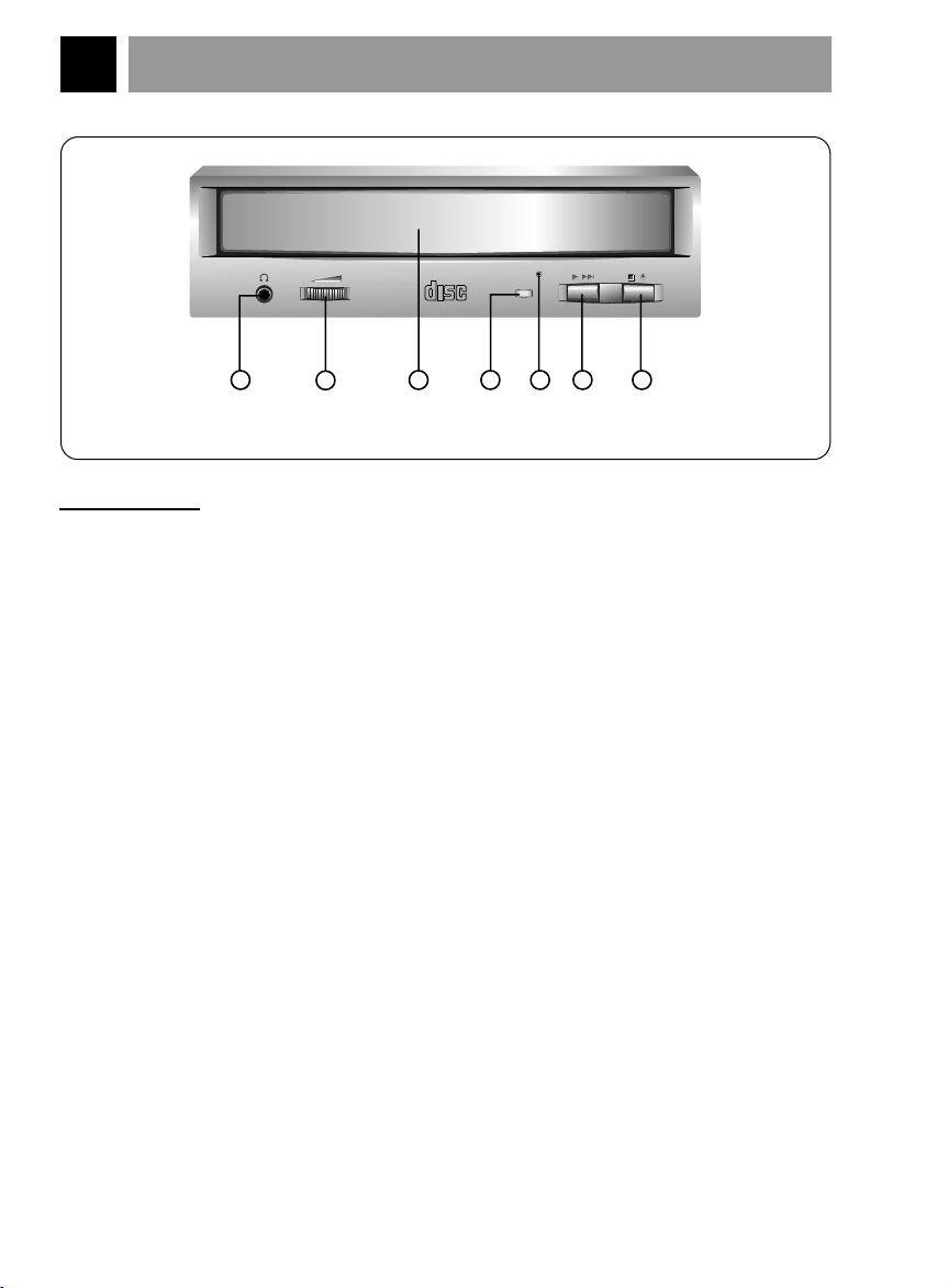
Figure 1. Front View
FRONT VIEW
1. Headphone Jack
3.5mm jack for monitoring the audio signal from audio CDs.
2. Headphone Volume Control
Adjusts the headphone sound level.
3. Disc Drawer
Accepts a CD-ROM disc on its tray.
4. Busy Indicator
The Busy Indicator lights during initialization and data-read operations.
5. Emergency Eject Hole
Insert a paper clip here to eject the drawer manually or when there is no power.
6. Play/Skip Button
When an Audio CD is in the Disc Drawer, pressing this button will start playing
audio CDs from the first track. If an audio CD is playing, pressing this button will
skip to the next track.
7. Open/Close/Stop Button
This button is pressed to open or close the CD tray.
The button works only when power is applied to the drive.
If an audio CD is playing, pressing this button will stop it, and pressing it
will open the tray.
E-4
again
Page 5
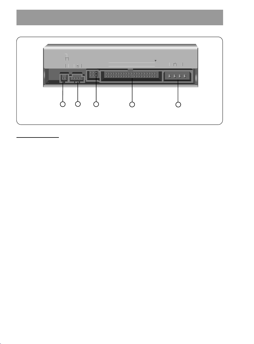
BACK VIEW
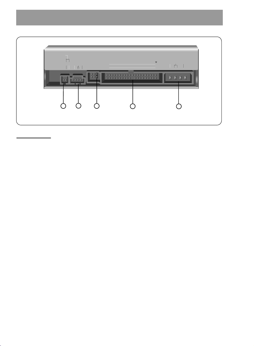
Figure 2. Back View
DIGITAL ANALOG
INTERFACE POWER
DR CSM
SLA
GLG39 1
+5
+12
GND
40 2
AUDIO AUDIO
1
2
5
4
3
1. Digital Audio Ouput Connector
This is a digital audio output connector or Video CD output connector.
You can connect this to the digital audio system or Video CD Board.
2. Analog Audio Output Connector
The Audio Output Connector connects to a sound card.
The supplied audio cable is a SoundBlaster
sound card, you will need to contact the sound card manufacturer to obtain the
proper cable for that card.
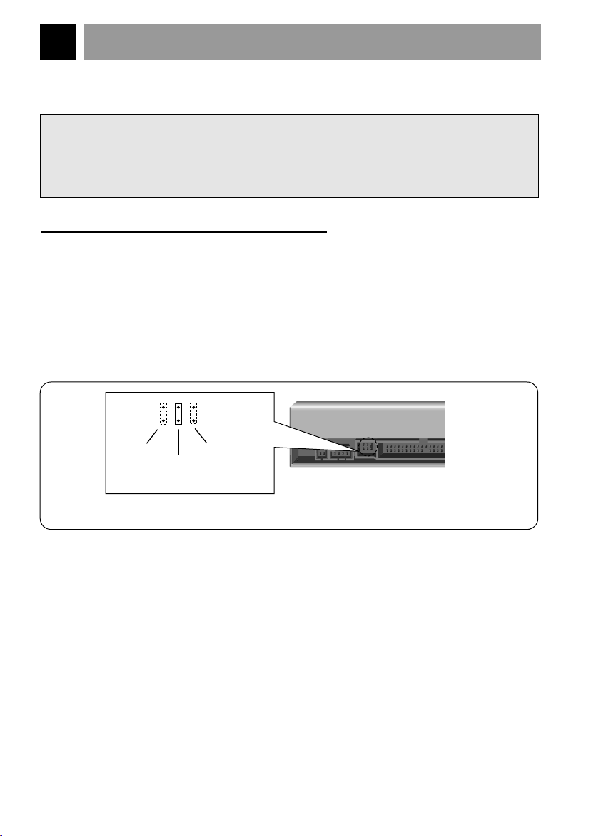
3. Master / Slave / CSEL Jumper
These three jumpers are used to set the CD-ROM Drive to either a Master, Slave,
or CSEL drive.
Refer to section HARDWARE INSTALLATION.
4. Interface Connector
This 40-pin connector is used to transfer and control signals between the
CD-ROM Drive and your PC.
Connect the 40-pin IDE cable in your PC to this connector.
®
type cable. If you have a different
5. Power-in Connector
Attach a power cable from the computer to this connector.
E-5
Page 6

INSTALLATION, USAGE AND HANDLING PRECAUTIONS
■ Installation
Avoid placing the drive in a location subject to :
- high humidity
- high temperature
- mechanical vibration
- direct sunlight
■ Operation
- During operation, excessive vibration or a sudden jolt to the drive may cause a
malfunction.
- Avoid exposing the drive to sudden changes in temperature. This may cause
condensation to collect inside the drive.
■ Transportation
- Always remove the disc before moving the drive.
E-6
Page 7
HARDWARE INSTALLATION
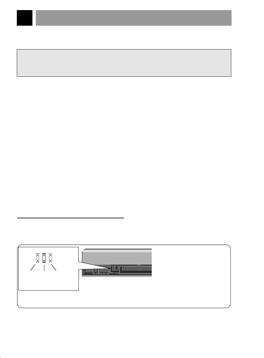
(rear of CD - ROM drive)
Note : The jumper is always
placed vertically,
NEVER SIDEWAYS!
CSEL
mode
SLAVE
mode
(default)
MASTER
mode
Figure 3. Setting MASTER / SLAVE Jumper
This section describes how to install your CD-ROM drive into your computer.
WARNING:
To protect the CD-ROM Drive, your computer, and peripheral devices from damage,
turn off their power before installing the drive.
Note: If you are not comfortable about opening your PC and attempting the CD-ROM
drive installation, many local computer shops can perform this service for a
reasonable cost.
This installation assumes you have a PC with an available connector on an IDE
interface cable. If your PC has an IDE hard drive, there is usually an available
connector in the middle of the same cable that attaches from the motherboard (or
controller card) IDE connector to the hard drive. If the last sentence does not describe
your system, you may need to purchase an IDE controller card to install this CD-ROM
drive. Inspecting and knowing your PC system will make your installation easier and
less time consuming.
A final note before installation: The cable connecting to your floppy disk drive is not an
IDE cable. Do not attempt to attach the CD-ROM drive to this cable.
If the CD-ROM drive is to be connected to the same cable as the hard drive, be sure
that the hard drive is set as master. Hard drives can be set as single, master, or slave.
Check your hard drive owner's manual or contact the hard drive manufacturer for
correct jumper settings.
SETTING MASTER / SLAVE JUMPER
* You will see three pairs of pins and a jumper (cap) at the back of the CD-ROM drive.
This jumper is used to set the CD-ROM Drive as a CSEL, MASTER, or SLAVE device in
your PC. Examples of how the jumper can be placed are shown in Figure 3 below.
* Move the jumper (clip on one pair of pins) from its default factory position (SLAVE), to
CSEL or MASTER as needed (see the following description for the setup that matches
your system), using the above diagram to place the jumper.
E-7
Page 8
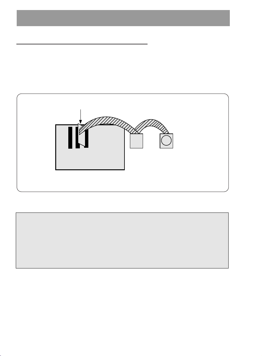
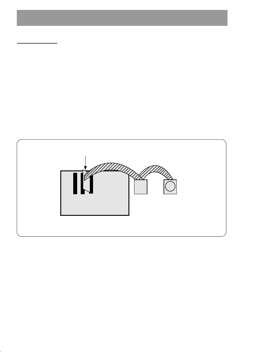
WHEN USING A PRIMARY IDE CONTROLLER
Hard Disk Controller Card
(This card may be a connector on the Motherboard)
Primary IDE Channel
Primary Slave
(Hard Disk or
CD-ROM Drive)
Primary Master
(Hard Disk for
Boot-up)
Card Slot
Motherboard
Figure 4. Primary Controller system Configuration
Most PCs provide one IDE cable to support two devices (one for hard disk, the other for a
second hard disk or a CD-ROM drive). This IDE cable originates either on the motherboard
or on a controller card. This controller is termed the primary IDE controller, and the hard
disk attached that contains the operating system for boot-up is set up as the Primary
Master. Your CD-ROM drive should be set to the Slave mode.
Note:
Many older 1X and 2X CD-ROM drives used a 40 pin controller card that were not
IDE compatible. These were proprietary interface cards for use with a particular
model CD-ROM Drive. Many older Sony, Panasonic, and Mitsumi drives used 40 pin
proprietary interface cards. If you are upgrading from an older CD-ROM drive, your
new CD-ROM will not work on a proprietary interface card. You will need to buy a
secondary IDE controller card.
E-8
Page 9
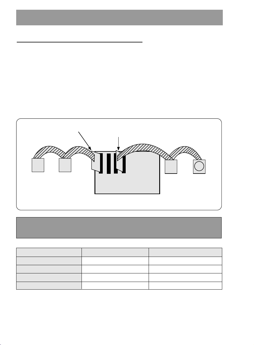
WHEN USING A SECONDARY CONTROLLER
Secondary IDE
Controller CARD
Hard Disk Controller Card
(This card may be a connector on the Motherboard)
Secondary IDE Channel
Primary IDE Channel
Secondary Master
(Hard Disk or
CD-ROM Drive)
Secondary Slave
(Hard Disk or
CD-ROM Drive)
Primary Slave
(Hard Disk or
CD-ROM Drive)
Primary Master
(Hard Disk for
Boot-up)
Card Slot
Motherboard
Figure 5. Possible System Configuration
* If your PC has an additional IDE controller on the motherboard or on a system slot, each
IDE device connected to the secondary IDE controller must also be set to the Master or
Slave mode. If you are connecting your CD-ROM drive to a secondary IDE card, and it is
the 1st device you are connecting to it, then set the CD-ROM jumper to the Master
position. If it is the 2nd device, set the CD-ROM jumper to the Slave position.
* Depending on the IDE card and whether the CD-ROM drive is a master or slave unit,
the diagram below represents the different ways in which the CD-ROM may be
configured in your PC. The table below the diagram shows the possible Jumper
placements that would correspond to each of the different configurations shown.
If you have the system with two IDE channels (in the case of an enhanced IDE PC),
do not install an IDE controller card in your system.
IDE Controller
Primary (1st IDE card)
Secondary (2nd IDE card)
Secondary (2nd IDE card)
PC Manual says use CSEL
CD-ROM Connection
Slave(Hard disk is Master)
Master(1st device on 2nd IDE Card)
Slave(2nd device on 2nd IDE Card)
E-9
Jumper Placement
SLAVE (default)
MASTER
SLAVE (default)
CSEL
Page 10
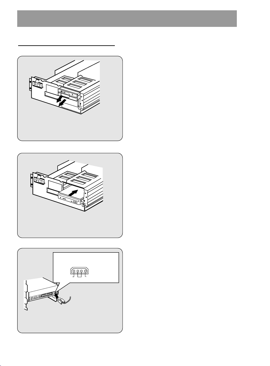
MOUNTING THE CD-ROM DRIVE
Figure 6. Removing the Floppy Disk
Drive and the Blanking plate
Figure 7. Mounting the Drive
Power supply connector
(4-pin connection cable)
Figure 8. Connecting the Power
Supply Cable
GND
Pin assignment
The pin assignment of the power-in
connector is as follows:
12V DC5V DC
Step 1. Turn off and unplug your
computer and all peripheral
devices attached to it.
Step 2. Remove the cover from your
computer.
Step 3. Remove the front panel from an
unused half-height slot.
Step 4. Slide the CD-ROM drive into the
half-height slot, and secure the
drive in place with screws and
brackets.
Note: If there is too much space between
the sides of the drive and the drive
bay, you may need to install spacer
brackets, available at your local
computer store.
Step 5. Push the power supply cable
connector firmly into the power in
connector.
E-10
Page 11
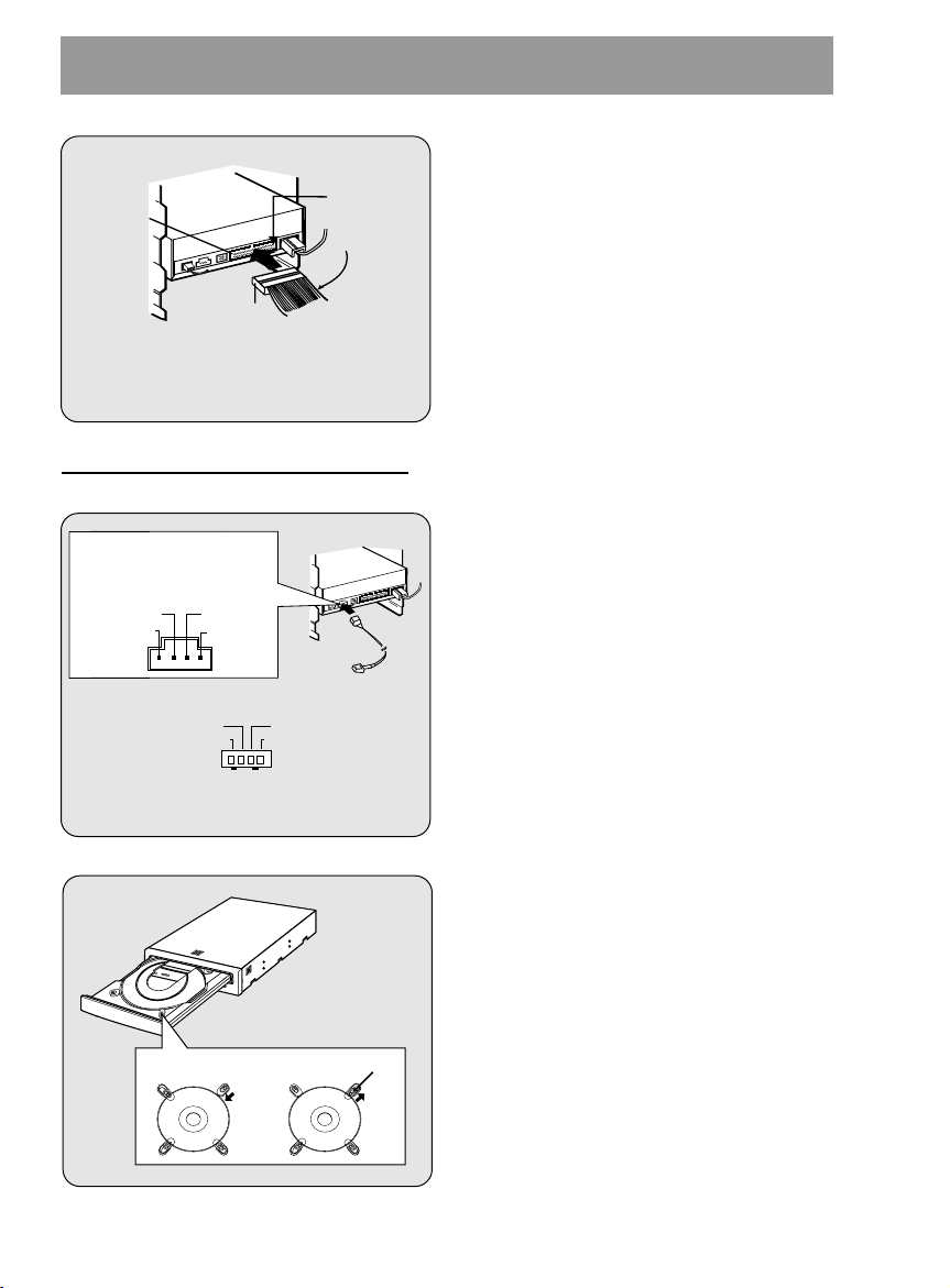
CONNECTING AN AUDIO CABLE
Red-edge
Pin 1
Interface
connector
IDE Cable
Figure 9. Connecting the IDE Cable
to the Interface Connector
L-Channel
GNDGND
R-Channel
* Pin assignment of the audio cable
to Audio
Equipment
(sound card)
Audio
Cable
L-Channel
GNDGND
R-Channel
Pin assignment
The pin assignment of the
audio output connector is
as follows.
Figure 10. Connecting an Audio Cable
to the Audio Output Connector
Disc Clips
Step 6. Connect the 40-pin IDE Cable to
the back of the CD-ROM Drive.
Please make sure that the red
edge of the IDE Cable is
connected to Pin 1 on the CDROM Drive.
If you want to connect audio equipment or
a sound card to the CD-ROM drive, use
an audio cable to connect the drive to the
sound device.
Note: This CD-ROM Drive can be used
vertically.
• To use the drive vertically, open the
drawer and move the 2 plastic clips on
the bottom to hold a disc vertically. After
placing a CD into the tray, move the top 2
plastic clips to hold the top of the CD in
place. Use only standard 12cm discs.
• Do not touch the unlabeled side of the
disc.
E-11
Page 12

SOFTWARE SET UP
THE SET UP PROCESS
The INSTALL program performs the following functions.
* Allows the user to select the target disk drive where CD-ROM device driver files will
be set-up.
* Unless modified by the user, the INSTALL program searches the target disk for
directory(\CDROM); if it is not found, the directory(\CDROM) is created.
* Copies the CD-ROM device driver file named GSCDROM.SYS, the Microsoft CD-ROM
Extension file named MSCDEX.EXE, and the utility files to the specified directory.
* Modifies your CONFIG.SYS file to list the location and name of the device driver.
* Modifies your AUTOEXEC.BAT file to load MSCDEX.
* Terminates and returns control to the user.
LIST OF FILES TO BE INSTALLED IN YOUR PC
✱ MSCDEX.EXE Microsoft MS-DOS CD-ROM Extension software, which
enables the computer to access the CD-ROM drive.
✱ GSCDROM.SYS CD-ROM device driver.
✱ EJECT.EXE Software eject program which can eject the CD tray.
✱ CLOSE.EXE Software close program which can close the CD tray.
✱ LOCK.EXE Program which disables the Eject Button.
The Eject Button will not function in the locked state.
The lock function is useful when you are using the
CD-ROM drive for important work.
✱ UNLOCK.EXE Program which enables Eject Button.
Eject Button will function properly after executing the
unlock program.
E-12
Page 13

RUNNING THE INSTALL PROGRAM (DOS INSTALLATION)
Step 1. Insert the CD-ROM device driver install diskette into the appropriate drive.
Step 2. Go to the floppy drive by typing A: or B: at the DOS prompt, as appropriate.
Step 3. Type the word INSTALL and press [ENTER].
Step 4. The INSTALL program will begin loading. When loading is complete, the
INSTALL program identification will appear on the screen.
Step.5. Follow the instructions on the screen.
Step 6. If you specify the path information during the installation, the install program will copy
the CD-ROM device driver file named GSCDROM.SYS, the Microsoft CD-ROM
Extension file named MSCDEX.EXE and the utility files to the specified directory,
and modify your CONFIG.SYS file and AUTOEXEC.BAT file.
Step 7. When the installation is completed, remove the diskette, and reboot your PC.
CD-ROM EXTENSION PROGRAM MSCDEX. EXE OPTIONS
There are several options that are set for the Microsoft CD Extension program.
Generally, these settings do not have to be changed for the CD-ROM drive to work, so
these options are needed no further. However, you may decide to change the MSCDEX
option settings depending on your operating environment.
These options are explained below:
PARAMETER
/D (Device Name)
/E
/L: (Device Name)
/M: (Value)
/V
DESCRIPTION
Tells MSCDEX.EXE what the device driver’s name is
(must be same as was used in "/D:" expression of
"DEVICE=" line in CONFIG.SYS file)
Tells MSCDEX.EXE to use expanded memory
Indicates the drive letter to be assigned to the CD-ROM
drive
Tells MSCDEX.EXE how much memory to allocated for
caching. Default is 10 (represents 10 kilobytes).
Provides memory usage statistics, such as how much
memory is used by buffers, resident data, and resident
code.
E-13
Page 14

ATAPI Installation (Windows 95 and others)
* For Windows 95 installation, do not use the installation diskette supplied. This CD-
ROM drive is Windows 95, Windows NT 3.5, and OS/2 Warp compatible, generally
utilizing the generic software drivers supplied with those operating systems Below is
the example installing the driver for Windows 95. For other operating systems, try
looking for either a LG Electronics or Goldstar IDE CD-ROM drive software driver. If
none is found, try selecting one of the device drivers for
(For Windows 95)
1. Install the CD-ROM drive in your PC as described in this manual.
2. Power up your PC. Upon starting Windows 95, it might automatically detect the new
CD-ROM drive and load the driver software for it. If not, proceed to the next step.
3. In Windows 95, Click on the Start button. Click on the Settings button. Click on the
Control Panel button. Double-Click on the Add New Hardware icon. Follow the
instructions for the computer to search your system for new hardware. It will locate
the CD-ROM drive and load the generic driver.
Non-listed IDE CD-ROM .
TROUBLESHOOTING
* When the CD-ROM drive does not work with the hard disk drive in primary
IDE channel.
(SOLUTION)
1. Check the CD-ROM drive Master/Slave Jumper setting.
The CD-ROM drive must be set to the Slave mode.
2. Check to be sure your hard disk Interface type is IDE type.
3. Check your hard disk Master/Slave Jumper setting.
Some old-version IDE type hard disks were set to Master Only mode.
In that case, contact your hard disk company and change your hard disk jumper
setting to master mode.
4. If the CD-ROM drive does not work with above methods, you may need a secondary
IDE card. If you use the secondary IDE card, you should set the CD-ROM drive
jumper to the master mode if the CD-ROM drive is the first device you are
connecting to the secondary IDE card.
* When the CD-ROM drive does not install in OS/2 warp.
(SOLUTION)
1. Select
NON-LISTED IDE CD.
* CD-ROM drive is not present in Windows 3.1 or 3.11 or DOSSHELL.
(SOLUTION)
1. When the WTN or DOSSHELL command lines are present in your AUTOEXEC.BAT,
make sure that the MSCDEX.EXE command line appears before the WIN or the
DOSSHELL command lines.
E-14
Page 15
SPECIFICATIONS
General
Data Capacity 553 Mbyte (mode 1), 635 Mbyte (mode 2)
Disc Diameter 12 cm / 8 cm
Rotational Speed 200 - 5,000 rpm
Performance
Interface E-IDE
Supported System IBM PC-AT or Compatible
Transfer rate Sustained Data Transfer Rate = Max 3600Kbytes/sec
Access Time Average 90ms(1/3 stroke)
MTBF 125,000 Power On Hours (Duty Cycle 10%)
Buffer size 128 Kbytes
Error Rate
ECC on 1block/10
ECC off 1block/10
User Data/Block 2,048 bytes/block (Mode1 & Mode2 Form1)
2,340, 2,336 bytes/block (Mode2)
2,324 bytes/block (Mode2 Form2)
2,352 bytes/block (CD-DA)
Supported Disc CD-DA, CD-ROM, CD-ROM XA-READY, Photo-CD
Audio Specifications
Frequency Response 100 Hz - 20 kHz +1/-3 dB
Dynamic Range 80 dB
S / N Ratio 85 dB
THD 0.01 % at 1 KHz
Channel Separation 80 dB at 1 KHz
Headphone Level 0.70 Vrms (33Ω)
Line Output Level 1.0 Vrms +
Line Output Jack 4 Pin terminal (Rear)
Headphone Jack ø 3.5 mm (Front)
15
bits(single), 1 block/1012bits (24x)
12
bits(single), 1 block/109bits (24x)
20% (47kΩ)
Environment
Temperature 5 - 45
°C
Power Requirements
12 V +
Ripple < 100m Vpp
5 V +
Ripple < 100m Vpp
NOTE: Specifications are subject to change without notice for improvement.
10%
5%
1.4A (Maximum)
0.8A (Maximum)
E-15
Page 16

CD-ROM LAUFWERK
BEDIENUNGSHANDBUCH
MODELL : CRD-8240B
Um alle Möglichkeiten und Funktionen lhres CD-ROM Laufwerkes voll
ausschöpfen zu können, lesen Sie bitte dieses Bedienungshandbuch
aufmerksam und völlständig.
Deutsch
Page 17
Achtung: Um die Gefahr eines elektrischen Schlages zu vermeiden, entfernen Sie nicht das Gehäuse.
COMPACT
Keine durch den Anwender zu reparierende Teile im lnnern.
Überlassen Sie den Service qualifiziertem Service-Personal.
Da der im CD-ROM Laufwerk benutzte Laser gefährlich für die Augen ist, sollten Sie keineswegs
versuchen, das Gehäuse zu öffnen.
Lassen Sie den Service nur durch qualifizierte Servicestellen durchführen.
Dieses Laufwerk ist kompatibel zu CD-ROM Disk
mit diesem Warenzeichen.
Warnung: Um die Gefahr eines Feuers oder eines elektrischen Schlages zu
vermeiden, setzen sie dieses Gerät niemals Regen oder Feuchtigkeit aus.
Dieses Produkt entspricht der EMC Richtlinie 89/336/EEC und ist
demnach mit dem CE Label gekennzeichnet.
D-2
Page 18
PRODUKTMERKMALE
PRODUKTMERKMALE
■ Enhanced - IDE Interface
■ 90 ms mittlere Zugriffszeit
■ Multimedia PC kompatibel
■ Multisession Photo CD fähig
■ geringe CPU Belastung (gemäß MPC Spezifikationen)
■ 24fach Datentransferrate
■ intelligente Datenbufferung
■ HIFI Audioausgabe
■ elektrische Schubladenzuführung ohne Caddy
■ zum internen Einbau vorgesehen
■ Notauswurffunktion
■ Einfache Handhabung durch Audio CD Bedienungstaste
SYSTEMVORAUSSETZUNGEN
Ein IBM TMPC TMkompatibles System mit folgenden Komponenten:
■ IBM kompatibles System mit min. 486 SX oder höher
■ mindestens 640 k Speicher
■ 3.5" Floppy Diskettenlaufwerk
■ MS-DOS Version 3.1 oder größer
* MITGELIEFERTES ZUBEHÖR
Bezeichnung
Bedienerhandbuch
Installationsdiskette
Audiokabel
IDE Controller Karte
Interface Kabel
Menge
1
1
1
1 (Optional)
1 (Optional)
D-3
Page 19

LAGE UND FUNKTION DER BEDIENELEMENTE
COMPACT
1
2
54 6 73
Abbildung 1. Frontansicht
FRONTANSICHT
1. Kopfhörerbuchse
3.5 mm Klinkenbuchse zum Mithören des Audiosignals
2. Kopfhörerlautstärkeregler
Regulieren Sie die Lautstärke der Kopfhörer
3. Diskschublade für eine CD-Disk
4. Betriebs-LED
Die Betriebs LED leuchtet während der Initialisierung und während des Lesens
von Daten.
5. Notauswurföffnung
Drücken Sie hier einen Draht ein, um die Schublade manuell zu öffnen.
6. Play/Skip (Abspielen/Weiterspringen) Taste
Bei Betätigen dieser Taste wird die Audio CD von Anfang an abgespielt. Erfolgt
das Betätigen der Taste während die CD abgespielt wird, so wird zur nächsten
Spur gewechselt.
7. Open/Close/Stop (Öffnen/Schließen/Stop) Taste
Drücken Sie diese Taste, um die Schublade zu öffnen oder zu schließen. Die
Auswurftaste arbeitet nur, wenn das Laufwerk am Strom angeschlossen ist.
Bei Drücken dieser Taste wird der Abspielvorgang der Audio CD gestoppt.
D-4
Page 20
RÜCKANSICHT
Abbildung 2. Rückansicht
DIGITAL ANALOG
INTERFACE POWER
DR CSM
SLA
GLG39 1
+5
+12
GND
40 2
AUDIO AUDIO
1
2
5
4
3
1. Digitaler Audio Ausgang
Dies ist ein digitaler Audio Ausgang bzw. Video-CD Ausgang.
Hierdurch können Sie eine Verbindung zum digitalen Audio System bzw. zur
Video-CD Schnittstellen-Karte (z.B. MPEG) herstellen.
2. Audioausgangbuchse
Dieser Steckverbinder dient der Verbindung mit Ihrer Soundkarte
3. Master/Slave/CSEL Jumper
Diese drei Jumper werden dazu benutzt das CD-ROM Laufwerk in den
"Master", "Slave" oder "CSEL" Modus zu setzen.
Lesen Sie hierzu Kapitel "Hardwareinstallation"
4. Interface Anschluß
Dieser 40 polige Steckverbinder wird zur Signalübertragung zwischen dem CDROM Laufwerk und Ihrem PC benutzt. Verbinden Sie das 40 polige IDE - Kabel
Ihres PC mit diesem Steckverbinder. Wenn Sie eine zweite IDE - Karte benutzen,
verbinden Sie diese Steckverbindung mit der zweiten IDE - Karte.
5. Spannungseingangbuchse
Stecken Sie das Stromversorgungskabel Ihres Computers in diese Steck-
verbindung.
D-5
Page 21

WARTUNG
Installation
■
Vermeiden Sie es das Laufwerk folgenden Umgebungsbedingungen auszusetzen:
- hohe Luftfeuchtigkeit
- hohe Temperatur
- mechanische Erschütterungen
- direktes Sonnenlicht
■ Benutzung
- Starke Vibrationen oder plötzliche Stöße während des Betriebes können
zu einer Fehlfunktion des Laufwerkes führen.
- Vermeiden Sie es das Laufwerk plötzlichen Temperaturwechseln auszusetzen.
Dies würde zu Kondenswasserbildung im Inneren des Laufwerkes führen.
■ Transport
- Entfernen Sie vor einem Transport immer die Disc.
D-6
Page 22
HARDWAREINSTALLATION
Abbildung 3. Konfigurationsjumper
CSEL
SLAVE
MASTER
(Standardeinstellung)
Dieser Abschnitt beschreibt den Einbau des CD-ROM Laufwerkes in Ihren Computer.
Warnung:
Um das CD-ROM Laufwerk und Ihren Computer, sowie Peripheriegeräte vor
Beschädigungen zu schützen, ziehen Sie den Netzstecker, bevor Sie das Laufwerk
einbauen.
SETZEN DES MASTER / SLAVE JUMPERS
* Auf der Rückseite des CD-ROM Laufwerkes sehen Sie drei Jumper.
Diese Jumper werden benutzt um das CD-ROM Laufwerk in den "CSEL",
"MASTER" oder "SLAVE" Modus zu setzen. Der Jumper muß in eine der drei
möglichen Positionen gesteckt werden.
Wenn der Jumper auf die "CS" Position gesetzt wird, sollte das Laufwerk das
CSEL Signal des Hostadapters zur Konfigurierung benutzen.
Die Jumper auf der Rückseite des Laufwerkes sollten nach Einbau zugänglich
bleiben.
D-7
Page 23
BEMERKUNG:
Festplattencontrollerkarte
(Diese Karte kann sich auch als Anschlu auf dem Motherboard befinden)
Erster IDE-Anschluß
Primary Slave
(Hard Disk or
CD-ROM Drive)
Primary Master
(Hard Disk for
Boot-up)
Card Slot
Motherboard
Abbildung 4. Mögliche Systemkonfiguration
Die meisten PC's unterstützen über einen Anschluß zwei Geräte (eine Festplatte, und
ein CD-ROM Laufwerk oder eine zweite Festplatte). Dieser IDE Anschluß befindet sich
entweder auf dem Motherboard oder auf einer Steckkarte.
Dies ist der erste (primary) IDE Adapter.
Falls das Betriebssystem von der Festplatte geladen wird, muß diese in den Master
Mode gesetzt sein und somit das CD-ROM Laufwerk in den Slave Modus gesetzt
werden.
* Wenn Ihr PC über einen zusätzlichen zweiten (secondary) IDE Controller auf dem
Motherboard oder auf einer Steckkarte verfügt, so muß jedes der an diesen zweiten
Controller angeschlossenen Geräte ebenfalls entweder in den Master oder den
Slave Mode gesetzt werden. In diesem Fall kann Ihr System vier Geräte
unterstützen: Primary Master, Primary Slave, Secondary Master, Secondary Slave.
D-8
Page 24

FALLS SIE EINEN ZWEITEN IDE CONTROLLER BENUTZEN
Zweite IDE-Controller Karte
Festplattencontrollerkarte
(Diese Karte kann sich auch als Anschlu auf dem Motherboard befinden)
Zweiter IDE-Anachluß
Erster IDE-Anschluß
Secondary Master
(Hard Disk or
CD-ROM Drive)
Secondary Slave
(Hard Disk or
CD-ROM Drive)
Primary Slave
(Hard Disk or
CD-ROM Drive)
Primary Master
(Hard Disk for
Boot-up)
Card Slot
Motherboard
Abbildung 5. Mögliche Systemkonfiguration
* Wenn Ihr PC über einen zweiten IDE Controller auf dem Motherboard oder auf
einem Slot verfügt, so muß jedes an den zweiten Controller angeschlossene Gerät
entweder in den Master- oder Slavemode gesetzt sein.
* "Primary Master" sollte die Festplatte mit dem Betriebssystem, von dem gebootet
wird sein.
Ihr CD-ROM Laufwerk kann "Primary slave", "Secondary Master" oder "Secondary
Slave" sein.
Falls Ihr CD-ROM Laufwerk "Secondary Slave" sein soll, so muß ein Gerät (Harddisk
oder CD-ROM) als "Secondary Master" angeschlossen sein.
Warnung:
Wenn Sie bereits ein Computersystem mit zwei IDE Anschlüssen besitzen
(sogenannte "Enhanced IDE PC) installieren Sie keine zweiten "secondary" IDE
Controller!
Primary Slave
Secondary Master
Secondary Slave
Use Csel
MODE
IDE Controller
Primary Controller
Secondary Controller
Secondary Controller
D-9
Jumper Einstellung
Slave Jumper gesetzt
Master Jumper gesetzt
Slave Jumper gesetzt
Use Csel Jumper gesetzt
Page 25

EINBAU DUS CD-ROM LAUFWERKES
Abbildung 6. Entfernung des
Floppylaufwerkes
und der Frontblende
Abbildung 7. Einbau des Laufwerkes
Spannungsversorgungsstecker
(4-poliges Kabel)
Abbildung 8.
Anschlu des
Spannungsversorgungskabels
GND
Pinbelegung
Der Spannungsversorgungseingang
ist wie folgt belegt :
12V DC5V DC
Schritt 1.Schalten Sie den Computer und
allen Pheripheriegeräte aus und
lösen Sie alleVerbindungskabel.
Schritt 2.Entfernen Sie den Deckel Ihres
Computers.
Schritt 3.Entfernen Sie die Frontblende
eines ungenutzten 5.25"
Einbauschachtes mit halber
Bauhöhe.
Schritt 4.Schieben Sie das CD-ROM
Laufwerk in den Einbauschacht,
und sichern Sie das Laufwerk
mit Einschubschienen und
Schrauben.
Schritt 5.Drücken Sie den Spannungs-
sversorgungsstecker vorsichtig
in dieSpannungseingangsbuchse.
D-10
Page 26

ANSCHLUß EINES AUDIOKABELS
Röte
PIN 1
Anschluß buchese
IDE-Kabel
Abbildung 9. Verbinden des IDE Kabels
mit der Schnittstelle
Abbildung 10. Verbinden des Audiokabel
mit der Audioausgangbuchse
linker Kanal
GNDGND
rechter Kanal
* Pinbelegung des Audiokabels
zum Audiogerät
(Soundkarte)
Audiokabel
rechter Kanal
GNDGND
linker Kanal
Pinbelegung des
Audioausgangs
Hook Disks
Schritt 6.Verbinden Sie das 40 polige
IDE Kabel mit dem Anschluß
auf der Rückseite des
Laufwerkes. Stellen Sie bitte
sicher, daß die röte Ader des
IDE-Kabels mit PIN 1 des CDROM Laufwerkes verbunden
ist.
Benutzen Sie ein Audiokabel um
Audiogeräte oder eine Soundkarte mit
dem CD-ROM Laufwerk zu verbinden.
Achtung: Dieses CD-ROM Laufwerk
kann in vertikaler Position
benutzt werden.
• Legen Sie erst eine 12cm CD in das
Laufwerk ein, nachdem die speziellen
Hook-Disks in die Schublade eingelegt
worden sind.
• CD s von 8cm Größe können nicht
gelesen werden. Vermeiden Sie die
Berührung der CD-Unterseite.
D-11
Page 27

SOFTWAREINSTALLATION
DER SETUP - VORGANG
Das INSTALL - Programm unterstützt die folgenden Funktionen.
* Erlaubt die Festlegung des Laufwerkes auf dem die CD-ROM Laufwerk Geräte-
treiber installiert werden, zu wählen.
* Wenn nicht vom Anwender geändert, sucht das INSTALL - Programm auf dem
Standardlaufwerk nach dem Verzeichnis (\CDROM) und richtet dieses ein falls es
nicht vorhanden ist.
* Kopiert den CD-ROM Laufwerk Gerätetreiber mit der Bezeichnung
"GSCDROM.SYS", die Microsoft Betriebssystemerweiterung "MSCDEX.EXE"
und einige Hilfsprogramme in das ausgewählte Verzeichnis.
* Ergänzt Ihr CONFIG.SYS File um den Gerätetreiberaufruf.
* Ergänzt Ihr AUTOEXEC.BAT File um den Ladeaufruf für MSCDEX.
* Beendet sich und übergibt die Systemkontrolle wieder an den Nutzer.
LISTE DER PROGRAMME DIE AUF IHREM PC INSTALLIERT WERDEN
✱ MSCDEX.EXE Microsoft MSDOS Betriebssystemerweiterung für den
Zugriff auf CD-ROM Laufwerke.
✱ GSCDROM.SYS CD-ROM Gerätetreiber.
✱ EJECT.EXE Software zum Öffnen der Schublade über ein Programm.
✱ CLOSE.EXE Software zum Schließen der Schublade über ein Programm.
✱ LOCK.EXE Software die Eject Taste des Laufwerkes sperrt.
Diese Funktion ist hilfreich gegen ein unbefugtes
Öffnen des Laufwerkes.
✱ UNLOCK.EXE Programm was die Sperre wieder aufhebt.
D-12
Page 28

STARTEN DES INSTALL - PROGRAMMS
Schritt 1.Schieben sie die CD-ROM Laufwerk Gerätetreiberdiskette in das 3.5"
Laufwerk.
Schritt 2.Wechseln Sie auf das Floppylaufwerk
Schritt 3.Geben Sie INSTALL ein und drücken Sie die [Enter] Taste
Schritt 4.Das INSTALL - Programm wird geladen. Wenn der Ladevorgang
abgeschlossen ist erscheint nachfolgendes Fenster:
Schritt 5.Folgen Sie den Anweisungen auf dem Bildschirm.
Schritt 6.Wenn Sie die Pfad-Informationen während der Installierung spezifizieren, werden
die CD-ROM Laufwerk Treiber-Datei "GSCDROM.SYS", die Microsoft CD-ROM
Erweiterungsdatei "MSCDEX.EXE" und die Utility Dateien vorn
Installierungsprogramm in das angegebene Verzeichnis hineinkopieret.
Gleichzeitig werden die CONFIG.SYS Datei und die AUTOEXEC.BAT Datei
modifiziert.
Schritt 7.Nach Abschluss der Installierung müssen Sie den PC erneut booten.
OPTIONEN DER CD-ROM BETRIEBSSYTEMERWEITERUNG MSCDEX.EXE
Es gibt eine Reihe von Optionen, die für die Microsoft Betriebssystemerweiterung
festgelegt werden müssen. Diese sind nachfolgend beschrieben:
PARAMETER
/D (Gerätename)
/E
/L: (Gerätename)
/M: (Größe)
/V
BESCHREIBUNG
Teilt MSCDEX.EXE den Namen des Gerätetreibers mit.
(dieser muß mit dem in der "DEVICE=" Zeile im "/D:"
Ausdruck benutzten Namen übereinstimmen)
Befiehlt MSCDEX.EXE expanded memory zu benutzen.
Gibt den Laufwerksbuchstaben an, der dem CD-ROM
Laufwerk zugewiesen wird.
Sagt MSCDEX.EXE wieviel Speicher der Cache
nutzen soll. Standardwert ist 10, was 10 kB entspricht.
Gibt statistische Informationen über die Speichernutzung
durch Buffer, residente Daten und residente Programme.
D-13
Page 29

FEHLERBEHANDLUNG
* Wenn das CD-ROM Laufwerk nicht mit der Festplatte an der "primary IDE I/O Adresse"
arbeitet.
(Lösung): 1. Überprüfen Sie den "Master/Slave Jumper" auf der Rückseite des
CD-ROM Laufwerkes. Das CD-ROM Laufwerk muß auf
Slave gesetzt werden.
2. Stellen Sie sicher, daß Ihre Festplatte wirklich eine IDE Festplatte ist.
3. Überprüfen Sie den "Master/Slave Jumper" auf der Rückseite der
Festplatte. Die Festplatte muß auf Master gesetzt werden. Einige
alte IDE- Festplatten wurden vom Hersteller auf "Master only"
gesetzt. In diesem Fall befragen Sie den Hersteller der Festplatte wie
Sie diese in den Master Modus setzen können.
4. Falls das CD-ROM Laufwerk nach Durchführung obiger Arbeiten
noch nicht funktioniert, benötigen Sie eine zweite IDE Karte. Wenn
Sie eine zweite IDE Karte benutzen müssen, ist es erforderlich den
"Master/Slave Jumper" des CD-ROM Laufwerkes auf "Master"
setzen.
* Wird OS/2 Warp nicht vom CD-ROM Laufwerk installiert.
(Lösung) 1. Wählen Sie "NON-LISTED IDE CD".
Warnung
1. Wenn Sie WIN oder DOSSHELL Kommando in Ihre AUTOEXEC.BAT einfügen
wollen, vergewissern Sie sich, ob die MSCDEX.EXE Datel vor dem Aufruf WIN
oder DOSSHELL steht.
D-14
Page 30

SPEZIFIKATIONEN
ALLGEMEINES
Datenlesekapazität 553 Mbyte (mode 1), 635 Mbyte (mode 2)
Diskdurchmesser 12 cm / 8 cm
Umdrehungsgeschwindigkeit 200 - 5000 rpm
GESCHWINDIGKEIT
Interface Enhanced IDE
unterstütztes System IBM PC-AT oder kompatible
Transferrate ständige Datentransferrate = maximal 3600Kbytes/s
Zugriffszeit im Mittel 90 ms (1/3 stroke)
Fehlerhäufigkeit 125,000 Stunden Einschaltdauer (bei 10% Zugriff)
Buffer Größe 128 Kbytes
Unterstützte logische
Blocklänge 2,048, bytes/block (Mode 1 & Mode 2 Form 1)
2,340, 2,336 bytes/block (Mode 2)
2,324 bytes/block (Mode 2 Form 2)
2,352 bytes/block (CD-DA)
dekodierbare Modi Audio, Mode 1, Mode 2-Form 1, Mode 2 -Form 2
AUDIO SPEZIFIKATIONEN
Frequenzbereich 100 Hz - 20kHz +1/-3dB
Dynamik Bereich 80 dB
S/N Verhältnis 85 dB
Klirrfaktor 0,01% bei 1 kHz
Kanaltrennung 80 dB bei 1 kHz
Kopfhörersignalpegel 0,70 Vss (33 Ohm)
Ausgangssignalpegel 1,0 Vss +
Ausgangssteckverbindung
Kopfhörerstecker 3,5 mm Klinkenstecker (Vorderseite)
4 pol Buchse (auf der Rückseite)
20% (47 KOhm)
UMGEBUNGSTEMPERATUR
Temperatur 5 - 45
STROMVERSORGUNG
12 V + 10%
Restwelligkeit < 100m Vss
5 V +
5%
Restwelligkeit < 100m Vss
1,4A (maximal)
0,8A (maximal)
°C
D-15
Page 31

UNITÉ LECTEUR
DE DISQUE CD-ROM
MODE D'EMPLOI
MODELE : CRD-8240B
Lisez attentivement et entièrement ce manuel, afin de pouvoir utiliser
toutes les caractéristiques et toutes les fonctions de votre appareil.
Français
Page 32

ATTENTION : Pour reduire les risques de decharges electriques, ne demontez pas le capot (ou le panneau
COMPACT
arriere) du lecteur.
Aucune des pieces internes ne doit etre manipulee par l'utilisateur.
Toute intervention doit etre effectuee par un personnel qualifie.
Le rayon laser utilisé dans le lecteur CD-ROM est invisible à l'ceil nu. N'essayez donc pas de
démonter le boîter. Pour toute intervention, adressez-vous à un personnel qualifié.
Cet appareil utilise des disques CD-ROM portant ce label :
AVERTISSEMENT : Pour réduire les risques d'incendie ou de choc électrique, n'exposez pas cet appareil à la pluie
ou à l'humidité.
F-2
Page 33

CARACTERISTIQUES
CARACTERISTIQUES
Interface E-IDE
Temps d'accès moyen : 90 ms
Compatibilité PC multimedia
Prise en charge de plusieurs sessions CD photo
Petite largeur de bande de l'unité centrale (spéc. MPC)
Système de transfert de données 24X-speed.
Système intelligent pour la mise des données en mémoire tampon
Haute fidélité audio
Chargement avec plateau sans système de caddy
Conçu pour un montager interne
Prise en charge de l'éjection en cas d'urgence
Réglage facile du son CD
CONFIGURATION DU SYSTEME REQUISE
PC IBM ou compatible avec les éléments suivants :
PC IBM compatible 486SX
Mémoire d'au moins 640 K
Lecteur de disquette (3 1/2 pouces)
Version 3.1 ou ultérieure de MS-DOS
✱
ACCESSOIRES FOURNIS AVEC LE LECTEUR:
Nom
Mode d'emploi
Disquette d'installation
Câble Audio
Carte Contrôleur IDE
Carte d'interface
F-3
Quantité
1
1
1
1 (en option)
1 (en option)
Page 34

EMPLACEMENT ET FONCTION DES COMMANDES
COMPACT
1
2
54 6 73
Figure 1. Face avant
FACE AVANT
1.
Prise casque
Prise jack de 3,5mm de diamètre pour le signal audio.
2.
Commande de volume du casque
Réglez le niveau du volume de votre casque à l'aide de cette commande.
3.
Plateau à disque
Installez le disque CD-ROM sur ce support.
4.
Témoin d'activité
Ce témoin ne s'allume que pendant l'initialisation et la lecture de données sur le disque.
5.
Trou d'éjection d'urgence
En foncez une tige à l'intérieur de ce trou pour ouvrir le support manuellement.
6.
Touche Play/Skip (de lecture/saut)
Lorsqu'un disque est installé sur le plateau, cette touche lance la lecture à partu de la
première plage. En cours de lecture, cette clle permet de passer à la prochaine plage du
disque.
7.
Touche Open/Close/Stop (ouverture/fermeture/arrêt)
Cette touche permet d'éjecter ou de fermer le plateau de lecteur.
Elle n'est opérationelle que si l'appareil est sous tension.
Si vous appuyez sur cette touche pendant la lecture d'un disque, la lecture s'arrête.
F-4
Page 35

PANNEAU ARRIÈRE
Figure 2. Panneau arrière
DIGITAL ANALOG
INTERFACE POWER
DR CSM
SLA
GLG39 1
+5
+12
GND
40
2
AUDIO AUDIO
1
2
5
4
3
1.
Connecteur de Sortie Audio/Video numérique
Ceci est un connecteur de sortie numérique Audio ou Video.
Vous pouvez l'utiliser pour connecter la carte audio numérique ou video numérique.
2.
Connecteur de sortie sonore
Le connecteur de sortie sonore est raccordé à la carte son.
3.
Cavalier maître/esclave
Le cavalier maître/esclave permet de configurer le lecteur CD-ROM en mode "Maître" ou
"esclave" lorsqu'il fonctionne avec votre disque dur.
4.
Connecteur d'interface
Acheminement des données. Raccordez le câble d'interface à ce connecteur et à la
carte' d'interface installée sur votre ordinateur.
5.
Connecteur d'alimentation
Ce connecteur sert à l'alimentation CC du lecteur. Raccordez le câble d'alimentation à
l'ordinateur et à ce connecteur.
F-5
Page 36

PRECAUTIONS
Installation
Evitez de placer le lecteur à un endroit exposé à:
- une forte humidité,
- une température élevée,
- des vibrations mécaniques,
- la lumière directe du soleil.
Fonctionnement
- Un choc brutal ou des vibrations excessives au cours de l'utilisation du lecteur
peuvent entraîner un mauvais fonctionnement de l'appareil.
- Evitez de soumettre le lecteur à de brusques changements de température.
Cela pourrait entraîner la formation de condensation à l'intérieur de l'appareil.
Transport
- Ne laissez jamais de disque à l'intérieur du lecteur pendant le transport.
F-6
Page 37

INSTALLATION MATERIELLE
Figure 3.Cavalier de configuration de l'unité
Utilisation de
CSEL
Esclave
(par défaut)
Maître
Cette section décrit la procédure à suivre pour installer le lecteur CD-ROM sur votre
ordinateur.
ATTENTION !!
Pour éviter d'endommager le lecteur, l'ordinateur et les unités périphériques, mettez
l'ordinateur et. toutes unités périphériques connectées hors tension avant de
procéder à l'installation matérielle.
RÉGLAGE DU CAVALIER EN MODE MAÎTRE/ESCLAVE
Vous trouverez à l'arrière du lccteur CD-ROM trois positions possibles pour le cavalier
maître/esclave.
Ces positions permettent de configurer l'unité en mode CSEL(CS). MAITRE(MA) ou
ESCLAVE(SL). Lorsque vous retirez le cavalier de la position CS, l'unite peut être
configurée en mode Maître(position MA) ou Esclave(position SL).
Lorsque vous réglez le cavalier sur la position CL(CSEL), la configuration de l'unité est
déterminée par le signal de l'ordinateur.
F-7
Page 38

UTILISATION D'UN CONTRÔLEUR IDE PRINCIPAL:
Carte contrôleur de disque dur
(Il peut s'agir d'un connecteur sur la carte mère)
Canal IDE Principal
Premier
esclave
(disque dur
ou CD-ROM)
Premier
maître
(disque dur
pour initialisation)
Emplacement
de la carte
Carte mère
Figure 4. Configurations possibles du système
Lu plupart des PC disposent d'un connecteur IDE capable de prendre en charge deux unités
(une pour un disque dur, l'autre pour un disque dur ou un lecteur CD-ROM). Ce connecteur
IDE se trouve soit sur la carte mère, soit sur une carte contrôleur.
Il s'agir d'un connecteur IDE principal.
Dans ce ens, l'unité de disque dur qui contient le système d'exploitation pour l'initialisation
doit être configuré en mode Maître (MA) et le lecteur CD-ROM en mode Esclave (SL).
F-8
Page 39

UTILISATION D'UN CONTRÔLEUR IDE AUXILIAIRE:
Carte contrôleur
IDE auxiliaire
Carte contrôleur de disque dur
(Il peut s'agir d'un connecteur sur la carte mère)
Canal IDE auxiliaire
Canal IDE principal
Maître auxiliaire
(disque dur ou
unité CD-ROM)
Esclave auxiliaire
(disque dur ou
unité CD-ROM)
Esclave
primcipal
(disque dur
ou unité CDROM)
Maître
principal
(disque dur
pour initalisation)
Emplacement
de la carte
Carte mère
Figure 5. Configuration possible du système
* Si votre PC dispose d'un contrôleur IDE auxiliaire sur la carte mère ou à un autre
emplacement du système, chaque unité IDE connectée au contrôleur IDE auxiliaire doit
également être configurée en mode Maître (MA) ou Esclave (SL).
Dans ce cas, votre système peut prendre en charge quatre unités périphériques,
configurées comme suit: Maître principal, Esclave principal, Maître auxiliaire et Esclave
auxiliaire.
*Maître principal doit correspondre au disque dur contenant le système d'exploitation pour
l'initialisation.
Enfin, le réglage du cavalier à l'arrière du lecteur permet de configurer votre unité CDROM comme Esclave principal, Maître auxiliaire ou Esclave auxiliaire. Si l'unité CD-ROM
est raccordée à un port auxiliaire comme Esclave, une unité Maître (disque dur ou antre
CD-ROM IDE) doit également correspondre à ce port.
ATTENTION:
Si vous avez un système avec deux canaux IDE (cas d'un PC amélioré), n'installez pas la
carte contrôleur IDE auxiliaire sur votre système.
MODE
Esclave principal
Maître auxiliaire
Esclave auxiliaire
Utilisation de CSEL
CONTROLEUR IDE
REGLAGE CAVALTER
Contrôleur principal
Contrôleur auxiliaire
Contrôleur auxiliaire
F-9
Cavalier sur SL
Cavalier sur MA
Cavalier sur SL
Cavalier sur CS
Page 40

MONTAGE DU LECTEUR CD-ROM
Figure 6. Démontage du lecteur
de disquette et du cache
Figure 7. Montage du lecteur
Connecteur d'alimentation
(cordon de raccordement 4 broches)
Figure 8. Raccordement du cordon
d'alimentation
GND
Affectation des broches
L'affectation des broches du connecteur
d'alimentation est la suivante :
12V CC5V CC
1. Eteignez et débranchez votre
ordinateur, ainsi que toutes les unités
périphériques qui sont connectées
dessus.
2. Enlevez le capot de l'ordinateur.
3. Démontez le panneau qui protège l'un
des emplacements inutilisés à mihauteur de l'appareil.
4. Faites glisser le lecteur CD-ROM dans
son emplacement et fixez-le à l'aide
des vis et des supports de fixation.
5. Branchez le cordon d'alimentation sur
le connecteur d'alimentation.
F-10
Page 41

RACCORDEMENT DU CABLE AUDIO
broche 1
Connecteur
d'interface
Câble IDE
Figure 9. Raccordement du câble IDE
au connecteur d'interface
Figure 10. Raccordement du câble audio
au connecteur de la sortie audio
Canal G
MasseMasse
Canal D
* affectation des broches du câble audio
Vers un matériel
audio (carte son)
Câble
Audio
Canal G
MasseMasse
Canal D
Affectation des broches
L'affectation des broches du
connecteur de sortie audio
est la suivante :
Crochet Disque
6. Raccordez le câble IDE 40 broches à
l'arrière de l'unité de lecteur CD-ROM.
Veillez à faire correspondre le côté
rouge du câble à la broche 1 sur
l'appareil.
Pour connecteur du matériel audio ou une
carte son sur le lecteur CD-ROM, utilisez un
câble audio.
NOTE: Ce lecteur CD-ROM peut être utilisé
verticalement
•
Insérer un cd 12cm dans le lecteur CDROM uniquement après que le le
<Crochet Disque> spécial situé sur le
tiroir soit mis en place.
•
Vous ne pouvez pas utiliser de CD 8cm
en position verticale. Ne pas toucher à la
face sans étiquette du CD.
F-11
Page 42

INSTALLATION DU LOGICIEL
PROCÈDURE D'INSTALLATION
Le programme INSTALL exécute les fonctions suivantes:
* Permet à l'unilisateur de sélectionner l'unité de disques destinataire pour l'installation
des fichiers pilotes de l'unité CD - ROM.
* A moins d'une intervention de l'utilisateur, recherche le répertoire \CDROM sur le
disque destinataire et le crée, s'il n'existe pas.
* Copic le fichier de l'unité CD - ROM intitulé "GSCDROM.SYS", le fichier d'extension
CD-ROM Microsoft "MSCDEX.EXE" et les fichiers des utilitaires dans le répertoire
spécifié.
* Modifie votre fichier CONFIG.SYS pour répertorier l'emplacement et le nom du pilote
de l'unité.
* Modifie votre fichier AUTOEXEC.BAT de manière à charger MSCDEX.
* Redonne la main à l'utilisateur à l'issue de l'installation.
LISTE DES FICHIERS À INSTALLER SUR VOTRE PC
✱ MSCDEX.EXE Logiciel d'extension CD-ROM MS-DOS de Microsoft, qui
permet à l'ordinateur d'accéder à l'unité CD-ROM.
✱ GSCDROM.SYS Pilote de l'unité CD-ROM.
✱ EJECT.EXE Programme du logiciel pour l'éjection du plateau de
disque.
✱ CLOSE.EXE Programme du logiciel pour la fermeture du plateau de
disque.
✱ LOCK.EXE Programme permettant de verrouiller la touche
d'éjection.
Une fois verrouillée, la touche d'éjection ne fonctionne
plus.
Cette fonction peut se révéler utile si vous utilisez le
lecteur de disque.
CD-ROM pour un travail important.
✱ UNLOCK.EXE Programme permettant de déverrouiller la touche
d'éjection.
Après l'exécution de ce programme, la touche d'éjection
fonctionne de nouveau normalement.
F-12
Page 43

LANCEMENT DU PROGRAMME INSTALL
a) Insérez la disquette d'installation contenant le programme pilote de l'unité CD - ROM
dans le lecteur adéquat.
b) Passer sur la disquette en tapant A: ou B: (selon le lecteur utilisé) à l'invite de DOS.
c) Tapez INSTALL et appuyez sur la touche [ENTER]
d) Le programme d'installation commence le chargement des fichiers. Lorsque
l'opération est terminée, l'écran suivant affiche le répertoire d'installation du
programme.
e) Suivez les instructions affichées l'ecran.
f) Si vous spécifiez le chemin pendant l'installation, le programme d'installation copiera
le pilote de l'unité CD - ROM "GSCDROM.SYS", le fichier d'extension CD-ROM
Microsoft "MSCDEX.EXE" et les utilitaires dans le répertoire spécifié et modifiera
automatiquement vos fichiers CONFIG.SYS, AUTOEXEC.BAT.
g) Une fois l'installation terminée, Redémarrez votre PC.
OPTIONS DU PROGRAMME D'EXTENSION CD-ROM MSCDEX.EXE
Piusreurs options doivent être définies dans le programme d'extension CD Microsoft.
PARAMETRE
/D (NOM D'UNITE)
/E
/L: (LETTRE D'UNITE)
/M: (VALEUK)
/V
DESCRIPTION
Indique à MSCDEX.EXE le nom du programme pilote
(nom suivant l'expression "/D:" dans la ligne "DEVICE" du
fichier CONFIG.SYS).
Signale à MSCDEX.EXE l'utilisation de la mémoire
étendue.
Indique la lettre affectée à l'unité de lecteur CD-ROM.
Indique à MSCDEX.EXE la quantité de mémoire affcetée à
l'antémémoire. La valeur par défaut est 10 (10 kilo-octets).
Fournit les statistiques sur l'utilisation de la mémoire
(quantité de mémoire utilisée pour les tampons, les
données résidentes et le code résidents).
F-13
Page 44

DÉPANNAGE
* Si le lecteur CD-ROM ne fonctionne pas lorsque l'unité de disque dur est iéglée sur
le canal d'E/S IDE principal.
(SOLUTION) 1. Vérifiez le cavalier maître/esclave du lecteur CD-ROM.
Il doit être réglé sur le mode esclave.
2. Vérifiez que l'interface du disque dur est bien du type IDE.
3. Vérifiez le réglage du cavalier maître/esclave de votre disquedur.
Les anciennes versions des disques durs de type IDE sont parfois
configurées en mode Maître seulement (Master Only).
Dans ce cas, contactez votre fournisseur de disque dur et modifiez le
réglage du cavalier pour passer en mode Maître.
4. Si le lecteur ne fonctionne toujours pas, vous aurez besoin de la carte
auxiliaire IDE (IDE secondary card).
* Quand le lecteur CD-ROM n'installe pas OS/2 warp.
(Solution) 1. Sélectionner < NON-LISTED IDE CD >
AVERTISSEMENT:
1. Si vous voulez ajouter la ligne de commande WIN ou DOSSHELL dans votre fichier
AUTOEXEC.BAT, veillez à les placer après la ligne de commande MSCDEX.EXE.
F-14
Page 45

POUR CEE
GÉNÉRALITÉS
Capacité 553 MO (Type 1), 635 MO (Type 2)
Diamètre des disques 12 cmd/ 8cm
Vitesse de rotation 200-5,000 tours/min
PERFORMANCES
Inferface E-IDE
Système compatible IBC PC-AT ou compatible
Débit de transfert Débit du transfert de données = Maxi 3600 Ko/sec
Temps d'accès En moyenne 90 msec
Durée de fonctionnement 125,000 heures (pourcentage d'utilisation 10%)
Taille de mémoire tampon 128 Ko
Taux d'erreurs 1 bloc/10
1 bloc/10
15
bits (code correcteur d'erreurs désactivé),
12
(code correcteur d'erreurs activé)
Longueurs blocs logiques acceptées 2,048 octets/bloc (Mode 1 & Mode 2 Forme 1)
2,340 2,336 octets/bloc (Mode 2)
2,324 octets/bloc (Mode 2 Forme 2)
2,352 octets/bloc (CD-DA)
DONNÉES TECHNIQUES AUDIO
Réponse en fréquence 100 Hz-20 KHz + 3 dB
Gamme dynamique 80 dB
Rapport signal/bruit 85 dB
Distorsion harmonique totale 0.01 % à 1 KHz
Séparation des canaux 80 dB à 1 KHz
Niveau du casque 0.70 V eff (33Ω)
Niveau de sortie ligne 1.0 V eff +
Prise sortie ligne Borne 4 broches (arrière)
Prise casque ø 3.5 mm (avant)
20% (47KΩ)
(1/3 stroke)
CONDITIONS D'UNTILISATION
Température 5-45
°C
ALIMENTATION
12V +10% 1.4 A (maximum)
Ondulation < 100m V crête à crête
+
5% 0.8 A (maximum)
5V
Ondulation < 100m V crête à crête
F-15
Page 46

CD-ROM DRIVE
MANUALE D'USO
MODELLO : CRD-8240B
La lettura attenta del presente manuale in ogni sua parte è necessaria per
potere approfittare appieno delle caratteristiche e delle funzioni offerte dal
CD-ROM Drive.
Italiano
Page 47

ATTENZIONE: Il laser impegato nel drive CD-ROM Drive potrebbe causare danni alla vista. Non si tenti
COMPACT
perciò di aprire la copertura.
Per ridurre il rischio di scossa elettrica, non togliete la copertura (né il pannello posteriore).
Non contiene nessuna parte che sia soggetta a manutenzione da parte dell'utente.
Per la manutenzione, ricorrete a personale di manutenzione qualificato.
Questo apparecchio fa uso di dischi CD-ROM
contrassegnati con questo simbolo:
ATTENZIONE:
Per ridurre il rischio di incendio o di scossa elettrica, questo apparecchio non deve essere esposto alla pioggia o
all'umidità.
I-2
Page 48

CARATTERISTICHE
CARATTERISTICHE
■ Interfaccia E-IDE
■ Tempo di accesso medio 90ms
■ Compatibile con PC multimedia
■ Supporto multisessione CD Photo
■ Larghezza di banda CPU piccola (spec. MPC)
■ Sistema di trasferimento dati 24x-speed
■ Sistema intelligente di bufferizzazione dei dati
■ Supporto audio ad alta fedeltà
■ Caricamento da tray[vassoio] senza sistema caddy[carrello]
■ Progettazione specifica per il montaggio interno
■ Supporto per l'Espulsione di Emergenza
■ Semplice supporto di comando a pulsante per il CD audio
REQUISITI DEL SISTEMA
PC IBM o compatibile con i seguenti componenti di sistema:
■ 486SX compatibile IBM o quanto indicato sopra
■ un minimo di 640K di memoria
■ un drive per floppy disk (da 3,5 pollici)
■ versione MS-DOS 3.1 o superiore
✱ Accessori forniti:
Nome
Manuale Utente
Dischetto per l'Installazione
Cavo Audio
Scheda di Comando IDE
Cavo di Interfaccia
Quantità
1
1
1
1 (Optional)
1 (Optional)
I-3
Page 49

POSIZIONE E FUNZIONAMENTO DEL COMANDI
COMPACT
1
2
54 6 73
Figura 1. Pannello frontale
PANNELLO FRONTALE
1. Uscita cuffia
jack da 3,5mm per il monitoraggio del segnale audio.
2. Comando di Regolazione del Volume della Cuffia.
Regolazione del livello sonoro della cuffia.
3. Cassetto del Dischetto
Può ricevere nel suo tray un dischetto CD-ROM.
4. Segnale di Occupato
Il segnale di Occupato si accende durante l'inizializzazione e durante le operazioni di
lettura dei dati.
5. Foro per l'Espulsione di Emergenza
Per l'espulsione manuale del cassetto, si inserisca un'asticciola in questo punto.
6. Pulsante Play/Skip [Riproduzione/Salta]
Quando il CD Audio si trova nel Cassetto dei Dischetti, l'attivazione di questo comando
permetterà di avviare la riproduzione del CD Audio dalla prima pista in poi. Se il CD
Audio sta riproducendo, l'attivazione di questo comando farà avanzare la riproduzione
alla pista successiva del CD Audio.
7. Pulsante Open/Close/Stop [Aperto/Chiuso/Stop]
Questo pulsante dovrà essere premuto per ottenere l'apertura o la chiusura del tray del
CD.
Il pulsante funziona solamente quando il drive riceve corrente.
Se il CD Audio sta riproducendo, lo si può fermare premendo questo pulsante.
I-4
Page 50

PANNELLO POSTERIORE
Figura 2. Pannello Posteriore
DIGITAL ANALOG
INTERFACE POWER
DR CSM
SLA
GLG39 1
+5
+12
GND
40
2
AUDIO AUDIO
1
2
5
4
3
1. Connettore Uscita Audio Digitale
Si tratta di un connettore per uscita audio digitale o di un connettore di uscita Video CD.
Si può collegare tale connettore al sistema audio digitale o alla scheda Video CD.
2. Connettore dell'Uscita Audio
Il Connettore dell'Uscita Audio é collegato con la scheda sonora.
3. Cavallotto Master/Slave/CSEL (Mastro/Schiavo/CSEL)
Questi tre cavallotti vengono usati per impostare il Drive CD-ROM come "Master",
"Slave", oppure "CSEL".
Si veda la sezione : "INSTALLAZIONE DELL'HARDWARE"
4. Connettore d'Interfaccia.
Questo connettore a 40 pin si usa per trasferire e gestire i segnali fra il Drive CD-ROM e il
proprio PC.
Si colleghi il cavo IDE a 40 pin del PC a tale connettore.
Se si fa uso della scheda IDE secondaria, si colleghi tale connettore alla scheda IDE
secondaria usando un altro cavo IDE a 40 pin.
5. Connettore per l'allacciamento elettrico
Si colleghi a questo connettore un cavo elettrico proveniente dal computer.
I-5
Page 51

INSTALLAZIONE, USO E PRECAUZIONI
■ Installazione
Si eviti di sistemare il drive in un luogo soggetto a:
- elevata umidità
- elevata temperatura
- vibrazioni meccaniche
- luce solare diretta
■ Funzionamento
- Durante il funzionamento, vibrazioni eccessive o scosse improvvise possono
alterare il funzionamento dell'apparecchio.
- Si eviti di esporre il drive ad improvvisi cambiamenti di temperatura.
Ciò potrebbe provocare la formazione di condenza al suo interno.
■ Trasporto
- Prima di spostare il drive, si abbia sempre la precauzione di togliere il dischetto.
I-6
Page 52

INSTALLAZIONE DELL'HARDWARE
Figure 3. Cavallotto di Configurazione dell'Apparecchio
Usare CSEL
Slave
(impostazione
assunta per
difetto)
Master
La presente sezione contiene istruzioni sul modo di installare il drive CD-ROM nel
computer.
ATTENZIONE:
Per evitare danneggiamenti al drive CD-ROM, al computer e ai dispositivi periferici, si
stacchi la corrente prima dell'installazione del drive.
IMPOSTAZIONE DEL CAVALLOTTO MASTER/SLAVE
* Sul retro del Drive CD-ROM troverete tre cavallotti.
Questi cavallotti servono per impostare il Drive CD-ROM su "CSEL", "MASTER" oppure
"SLAVE". Quando viene tolto un cavallotto cortocircuitante [shorting] nella posizione "CS"
(CSEL), il dispositivo usa per la sua configurazione della posizione di cavallotto "MA"
(Master) oppure "SL" (Slave).
Quando si inserisce il cavallotto "GS", l'apparecchio fa uso del segnale di interfaccia host
CSEL per la sua configurazione. I cavallotti di configurazione dell'apparecchio dovranno
essere accessibili dal retro del drive.
I-7
Page 53

SE SI FA USO DI UN CONTROLLORE IDE PRIMARIO
Scheda di Comando del Disco Rigido
(Questa scheda può essere un connettore della scheda madre)
Canale Primario IDE
Slave Primario
(Disco Rigido o
Drive CD-ROM)
Master Primario
(Disco Rigido per il
Bootstrapping)
Slot per le Schede
Scheda madre
Figura 4. Una possibile configurazione di sistema
La maggior parte dei PC forniscono un connettore IDE per il supporto di due dispositivi (uno per
il disco rigido, l'altro per il disco rigido o per il Drive CD-ROM). Tale connettore IDE si trova o
sulla scheda madre o su una scheda di comando.
Questo è il connettore IDE primario.
In questo caso, il drive del disco rigido che contiene il sistema operativo per il bootstrapping
[introduzione di una sequenza di chiamata] dovrà essere impostato in modo Master, e il Drive
CD-ROM dovrà essere impostato in modo Slave.
I-8
Page 54

SE SI FA USO DI UN CONTROLLORE IDE SECONDARIO
Scheda di Comando dell'IDE Secondario
Scheda di Comando del Disco Rigido
(Questa scheda può essere un connettore della Scheda Madre)
Canale IDE Secondario
Canale IDE Primario
Master Secondario
(Disco Rigido o
Drive CD-ROM)
Slave Secondario
(Disco Rigido o
Drive CD-ROM)
Slave Primario
(Disco Rigido o
Drive CD-ROM)
Master Primario
(Disco Rigido per
Bootstrapping)
Slot per le Scheda
Scheda madre
Figura 5. Una possibile configurazione di sistema
* Se il PC dell'utente possiede un ulteriore controllore IDE secondario nella scheda madre
oppure in uno slot del sistema, anche ciascun dispositivo IDE collegato al controllore IDE
secondario dovrà essere impostato in modo Master o Slave.
In questo caso, il sistema dell'utente può supportare fino a quattro dispositivi: Master
Primario, Slave Primario, Master Secondario e Slave Secondario.
* Il Master Primario dovrà essere il disco rigido che contiene il sistema operativo per il
bootstrapping.
Infine, il Drive CD-ROM potrà essere Slave primario, Master Secondario oppure Slave
Secondario, e potrà essere impostato configurando il cavallotto sul retro del Drive CDROM. Se il Drive CD-ROM è collegatoo alla porta secondaria come slave, il dispositivo
master (disco rigido o un altro CD-ROM IDE) dovrà essere presente in quella porta.
ATTENZIONE:
Se il sistema dell'utente ha due canali IDE (nel caso di PC IDE arricchito), non si installi nel
proprio sistema la scheda di comando IDE secondaria.
MODO
Slave Primario
Master Secondario
Slave Secondario
Usare Csel
CONTROLLORE IDE
Controllore Primario
Controllore Secondario
Controllore Secondario
I-9
IMPOSTAZIONE DEL CAVALLOTTO
Cavallotto Slave Coperto
Cavallotto Master Coperto
Cavallotto Slave Coperto
Usare il Cavallotto Csel Coperto
Page 55

MONTAGGIO DEL DRIVE CD-ROM
Figura 6. Togliere il Drive del Floppy
Disk e la Piastra di Soppressione
Figura 7. Montaggio deo Drive
Connettore per l'alimentazione di
corrente (cavo con connettore a 4 pin)
Figura 8. Collegamento del cavo
di Aimentazione di Corrente.
TEEEA
Assegnazione dei pin del connettore
per l'alimentazione elettrica è la seguente :
+12V Corrente
Continua
+5V
Corrente Continua
1. Spegnere e staccare dalla corrente il
computer e tutti i dispositivi pereferici ad
esso collegati.
2. Togliere la copertura dal computer.
3. Togliere il pannello frontale da uno slot
non utilizzato a metà altezza.
4. Inserire il drive CD-ROM nello slot a
metà altezza, e fermare il drive con viti e
staffe.
5. Inserire, premendo con forza, il
connettore del cavo dell'alimentazione
elettrica nel connettore di corrente.
I-10
Page 56

COLLEGAMENTO DI UN CAVO AUDIO
Pin 1
Connettore
dell'interfaccia
Cavo IDE
Figura 9. Collegamento del Cavo IDE
al Connettore di Interfaccia.
Figura 10. Collegamento di un Cavo Audio
al Connettore dell'Uscita Audio
Canale Sinistro
Terra
Terra
Canale Destro
* Assegnazione dei pin del cavo audio
da collegare ad
un Apparecchio
Audio (Scheda Sonora)
Cavo
Audio
Canale Sinistrol
TerraTerra
Canale Destro
Assegnazione dei pin
L'assegnazione dei pin del
connettore dell'uscita audio
è la seguente :
Blocca-Disco
6. Collegare il Cavo IDE a 40 pin al retro
del Drive CD-ROM. Ci si assicuri che
l'estremità rossa del Cavo IDE sia
collegata al Pin 1 del Drive CD-ROM.
Se si desidera collegare al Drive CD-ROM
un apparecchio audio oppure una scheda
sonora, si usi uncavo audio per collegare il
drive al dispositivo sonoro.
Nota: Questo lettore di CD-ROM può
essere usato in posizione verticale.
• Inserire un disco da 12cm nel lettore
soltanto dopo aver sistemato lo speciale
Blocca-Disco sul porta dischetti.
• Non si può usare in verticale un disco
da 8cm. Non toccare il lato non
etichettato del dischetto.
I-11
Page 57

INSTALLAZIONE DEL SOFTWARE
IL PROCEDIMENTO SET-UP [PREDISPOSIZIONE]
Il programma INSTALL svolge le seguenti funzioni:
* Permette all'utente di selezionare il disk drive di destinazione in cui saranno impostati i file
del driver del dispositivo CD - ROM Drive.
* A meno che non sia modificato dall'utente, il programma INSTALL cerca il disco
destinazione per la directory (\CDROM), e, se non la trova, crea la directory (\CDROM).
* Copia il file del driver del dispositivo CD - ROM Drive di nome "GSCDROM.SYS", il file
Microsoft di Estensione CD-ROM di nome "MSCDEX.EXE", e i file utility nella directory
specificata.
* Modifica il file CONFIG.SYS dell'utente aggiungendo nell'elenco la posizione e il nome del
driver del dispositivo.
* Modifica il file AUTOEXEC.BAT dell'utente in manera che carichi MSCDEX.
* Termina le operazioni e restituisce il comando all'utente
ELENCO DEI FILE DA INSTALLARE NEL PC DELL'UTENTE
*MSCDEX.EXE Software Microsoft di Estensione MS.DOS CD-ROM, che
permette al computer di accedere al drive CD-ROM.
*GSCDROM.SYS Driver del dispositivo CD-ROM.
*EJECT.EXE Programma di espulsione del software che può espellere il tray
del CD.
*CLOSE.EXE Programma di chiusura del software che può chiudere il tray
del CD.
*LOCK.EXE Programma che disabilita il Pulsante Eject [di Espulsione].
Il Pulsante Eject non funziona nello condizione bloccata
"locked". La funzione lock è utile quando si usa il Drive CDROM per lavori importanti.
*UNLOCK.EXE Programma che abilita il Pulsante Eject.
Il Pulsante Eject funziona correttamente dopo l'esecuzione del
programma di sblocco "unlock".
I-12
Page 58

ESECUZIONE DEL PROGRAMMA INSTALL (Versione MS-DOS)
1. Inserire il dischetto di installazione del driver del dispostivo CD-ROM Drive nel drive
appropriato.
2. Attivare il drive dei floppy disk digitando A: oppure B: secondo il caso, su richiesta del
DOS.
3. Digitare la parola INSTALL e premere "ENTER(INVIO)"
4. Il programma INSTALL comincerà a caricare. Alla fine dell'operazione, l'identificativo del
programma INSTALL apparirà sullo schermo.
5. Seguire le istruzioni che appariranno sullo schermo.
6. Se si specificheranno le informazioni sul percorso durante l'installazione, il programma di
installazione copierà il file del driver del dipositivo CD-ROM Drive denominato
"GSCDROM.SYS", il file Microsoft di Estensione CD-ROM denominato "MSCDEX.EXE" e i
file utility nella directory specificata, e modificherà automaticamente i file CONFIG.SYS,
AUTOEXEC.BAT.
7. Ad installazione ultimata, l'utente dovrà rifare il bootstrapping del proprio PC.
OPZIONI MSCDEX.EXE DEL PROGRAMMA DI ESTENSIONE CD-ROM
Sono queste diverse opzioni che devono essere impostate per il programma Microsoft di
Estensione CD .
Tali opzioni sono descritte qui di seguito:
PARAMETRO
/D (Nome del Dispositivo)
/E
/L: (Nome del Dispositivo)
/M: (Valore)
/V
DESCRIZONE
Dice a MSCDEX.EXE il nome del driver del dispositivo (deve
essere lo stesso di quello usato nell'espressione "D:" della riga
"DEVICE=" del file CONFIG.SYS).
Dice a MSCDEX.EXE di usare la memoria espansa.
Indica la lettera drive da assegnare al driver CD-ROM.
Dice a MSCDEX.EXE quanta memoria deve essere assegnata
al caching [memoria nascosta]. Il valore usato per difetto è 10
(che rappresenta 10kilobyte).
Fornisce statistiche d'uso della memoria, come quanta
memoria è usata dai buffer, dai dati residenti e dal codice
residente.
I-13
Page 59

ATAPI INSTALLAZIONE (WINDOWS '95, ALTRI)
Per l'installazione del CD ROM drive in ambiente windows '95, non usare il driver contenuto
nel floppy disk "MS-DOS CD-ROM EXTENTIONS WITH DEVICE DRIVERS".
Questo CD ROM drive è compatibile con Windows '95, Windows NT 3.5 e OS/2 Warp,
utilizzando generalmente il driver supportato dai sistemi di cui sopra come per l'esempio
successivo di Windows '95.
Per altri sistemi operativi quando è disponibile utilizzate i driver IDE CD-ROM della LG
Electronics o GoldStar altrimenti selezionate IDE CD-ROM non in elenco.
(Per Windows '95)
1. Installare il CD ROM drive nel computer seguendo le istruzioni del manuale.
2. Accendere il computer. Durante la fase di avviamento di Windows '95, automaticamente
potrebbe identificare il CD-ROM e caricare il driver, altrimenti procedere con le istruzioni.
3. Quando siete entrati in Windows '95 fare click sul pulsante di start, quindi su quello di
configurazione (Setting). Fare click sul pannello di controllo e quindi doppio click
sull'icona Aggiungere Nuovo Hardware. Seguire le istruzioni del software e definire il
driver generico.
RICERCA DEGLI ERRORI
* Quando il Drive CD-ROM non funziona con il drive del disco Rigido nel calale primario IDE
I/O:
(SOLUZIONE) 1. Si verifichi l'impostazione dei Cavallotti Mater/Slave del Drive CD-ROM.
2. Si verifichi che l'Interfaccia del proprio disco rigido sia del tipo IDE.
3. Si verifichi l'impostazione dei Cavallotti Master/Slave del proprio disco
rigido. Alcuni dischi rigidi del tipo IDE vecchia versione erano per lo più
impostati in modo Master Only (Solo Master).
In tal caso, contattare il proprio fornitore del disco rigido e cambiare
l'impostazione dei cavallotti del disco rigido in modo Master.
4. Se il Drive CD-ROM non funziona in nessuno dei modi sovradescritti, è
necessaria la scheda IDE secondaria. Se la scheda IDE secondaria è in
uso, sarà necessario impostare il Drive CD-ROM in modo Master.
* Quando il lettore di CD-ROM non installa OS/2 Warp.
(SOLUZIONE) 1. Selezionare "NON LISTED IDE CD" (Letteri IDE non in elenco).
ATTENZIONE:
1. Se si desidera aggiungere la riga del comando WIN o DOSSHELL in AUTOEXEC.BAT, ci
si assicuri che la riga del comando MSCDEX.EXE appaia prima della riga del comando
WIN oppure DOSSHELL.
I-14
Page 60

SPECIFICHE
GENERALITÀ
Capacità di Dati 553Mbyte (modo 1), 635 Mbyte (modo 2)
Diametro del Disco 12 cm/8 cm
Velocità di Rotazione 200 - 5,000 giri al minuto
CARATTERISTICHE
Interfaccia E-IDE
Systema supportato IBM PC-AT o Compatibile
Velocità di trasferimento Velocità di trasferimento dati sostenuta
Tempo di accesso Media di 90 ms (1/3 stroke)
MTBF 125,000 Ore di Accensione (Ciclo di servizio 10%)
Dimensione del buffer 128 Kbyte
Frequenza di errore
ECC acceso 1 blocco/10
ECC off 1 blocco/10
Logico supportato
Lunghezza del Blocco 2,048 byte/blocco (Mode 1 & Mode 2 Form 1)
SPECIFICHE AUDIO
Risposta Frequenza 100 Hz - 20 kHz +1/-3 dB
Gamma dinamica 80 dB
Rapporto S/N 85 dB
THD 0.01% a 1 KHz
Separazione dei Canali 80 dB a 1 KHz
Livello Cuffia 0.70 Vrms (33Ω)
Livello Uscita Linea 1.0Vrms +
Jack Uscita Linea Terminale a 4 pin (Rear)
Jack Cuffia ø 3.5mm (Davanti)
=Massimo 3600 Kbyte/sec
15
bit (singolo),
1 blocco/10
1 blocco/10
12
bit (24x)
12
bit (singolo),
9
bit (24x)
2,340, 2,336 byte/blocco (Mode 2)
2,324 byte/blocco (Mode 2 Form 2)
2,352 byte/blocco (CD-DA)
20% (47kΩ)
AMBIENTE
Temperatura 5 - 45
°C
REQUISITI DI POTENZA
12 V + 10%
Ondulazione < 100m Vpp
5 V + 5%
Ondulazione < 100m Vpp
NOTA: Le suddette specifiche possono variare senza preavviso a causa dei
1.4A (Massimo)
0.8A (Massimo)
miglioramenti apportati al materiale.
I-15
Page 61

UNIDAD CD-ROM
MANUAL DE USUARIO
MODELO : CRD-8240B
Para disfrutar de todas la posibilidades y funciones de su unidad
CD-ROM, lea este manual de usuario atentamente.
Spanish
Page 62

PRECAUCION: PARA REDUCIR EL RIESGO DE DESCARGA ELECTRICA NO RETIRE LA TAPA.
COMPACT
SOLO SE PERMITE LA REPARACION A PERSONAL CUALIFICADO.
El láser utilizado en el CD-ROM puede dañar sus ojos. No intente abrir la tapa.
Esta unidad CD-ROM utiliza discos CDROM marcados con este simbolo:
ADVERTENCIA: Para reducir el riesgo de incendio o descarga eléctrica, no
exponga este aparato a la lluvia o la humedad.
S-2
Page 63

CARACTERISTICAS
CARACTERISTICAS
■ Interface E-IDE.
■ Tiempo medio de acceso de 90ms.
■ Compatible con PC multimedia.
■ Soporta Photo CD Multisesión.
■ Ancho de banda de CPU pequeño (MPC espec.)
■ Sistema de transferencia de datos de 24x velocidad
■ Sistema de buffer de datos inteligente.
■ Soporta audio de alta fidelidad.
■ Bandeja de carga sin sistema caddy.
■ Diseñado para montaje interno.
■ Incorpora expulsión de emergencia.
■ Incorpora mandos para un control fácil de CD Audio
REQUISITOS DEL SISTEMA
■ IBM compatible 486SX o superior
■ Un mínimo de memoria de 640Kb.
■ Disquetera de 3.5.
■ Versión de MS-DOS 3.1 o superior.
ACCESORIOS SUPLEMENTARIOS :
Nombre
Manual de usuario
Diskette instalación
Cable audio
Cantidad
1
1
1
S-3
Page 64

LOCALIZACION Y FUNCIONES DE LOS CONTROLES
COMPACT
1
2
54 6 73
Figura 1. Vista frontal
VISTA FRONTAL
1. Conector para auriculares de audio
Jack de 3,5mm para monitorizar la señal de audio.
2. Control de volumen de auriculares.
Ajusta el nivel de sonido de los auriculares.
3. Bandeja de disco
Acepta un disco CD-ROM.
4. Indicador de trabajo
El indicador de trabajo luce durante la inicialización y las operaciones de lectura
de datos.
5. Orificio de expulsión de emergencia.
Inserte un alambre para expulsar manualmente la bandeja.
6. Botón de reproducción/avance
Una vez introducido un Audio CD pulsando este botón se empezará a reproducir
el Audio CD desde la primera pista. Pulsando este botón de nuevo se posicionará
al inicio de la siguiente pista.
7. Botón de apertura/cierre
Se presiona este botón para abrir o cerrar la bandeja.
Este botón solo funciona cuando la unidad está alimentada.
S-4
Page 65

VISTA POSTERIOR
Figura 2. Vista posterior
DIGITAL ANALOG
INTERFACE POWER
DR CSM
SLA
GLG39 1
+5
+12
GND
40 2
AUDIO AUDIO
1
2
5
4
3
1. Conector de salida de audio digital.
Es un conector de salida de audio digital o de video CD. Puede enchufar
este conector a su sistema do audio digital o a su tarjeta de video CD.
2. Conector de salida de audio
El conector de salida de audio se conecta a la tarjeta de sonido.
3. Puente Maestro/Esclavo/CSEL
Estos 3 puentes son para la configuración de la unidad CD-ROM como
Maestro, Esclavo o CSEL.
Ver sección "INSTALACION DEL HARDWARE"
4. Conector de interface
Este conector de 40 pines se utiliza para transferir y controlar las señales
entre la unidad CD-ROM y el PC.
Conecte el cable IDE de 40 pines del PC a este conector.
Si utiliza una tarjeta IDE secundaria, conecte este conector a la tarjeta
secundaria usando otro cable de 40 pines IDE.
Ver sección "INSTALACION DEL HARDWARE"
5. Conector de alimentación
Conecte un cable de alimentación desde el ordenador a este conector.
S-5
Page 66

INSTALACION, USO Y PRECAUCIONES DE MANEJO
■ Instalación
Evite colocar esta unidad en lugares expuestos a:
- alta humedad
- altas temperaturas
- vibraciones mecánicas
- luz solar directa
■ Operación
- Durante la operación, la vibración excesiva o movimiento brusco puede causar
un mal funcionamiento.
- Evite la exposición a cambios repentinos de temperatura, esto puede causar
una condensación dentro de la unidad.
■ Transporte
- Retire siempre el disco antes de mover la unidad.
S-6
Page 67

INSTALACION DEL HARDWARE
Figure 3. Posible configuración de puentes
Usando
CSEL
Esclavo
(por defecto)
Maestro
Esta sección describe como instalar su unidad CD-ROM en su ordenador.
AVISO:
Para proteger de posibles daños a la unidad CD-ROM, a su ordenador y a
dispositivos periféricos, desconecte la alimentación antes de instalar la unidad.
SELECCIÓN MAESTRO/ESCLAVO
* Existen 3 puentes en la parte posterior de la unidad CD-ROM. Estos puentes son
utilizados para seleccionar el modo de la unidad como "CSEL", "MAESTRO" o
"ESCLAVO". Si se retira el puente de la posición "CS"(CSEL), el dispositivo debe
configurarse en la posición "MA"(maestro) o "SL"(esclavo).
Si se configura el puente "CS", el dispositivo debe utilizar la señal CSEL del
interface IDE para configurar el dispositivo. Los puentes de configuración del
dispositivo son accesibles desde la parte posterior de la unidad.
S-7
Page 68

CUANDO SÓLO SE UTILIZA UNA ÚNICA CONTROLADORA IDE
Tarjeta controladora de disco duro
(Esta tarjeta puede ser un conector de la placa madre)
Canal IDE primario
Esclavo primario
(Disco duro o
unidad CD-ROM)
Maestro primario
(Disco duro
para arranque)
ranuras de tarjetas
Placa madre
Figura 4. Posible configuración del sistema
La mayoría de los PCs incorporan un conector IDE para soportar dos dispositivos (uno
para el disco duro, el otro para un segundo disco duro o una unidad CD-ROM). Este
conector IDE se encuentra en la placa base o en una tarjeta controladora.
Esto es lo que se denomina controlador IDE primario.
En este caso, el disco duro que contiene el sistema operativo para el arranque tiene
que estar en modo Maestro, y su unidad CD-ROM debería estar en modo Esclavo.
S-8
Page 69

CUANDO SE UTILIZA UNA SEGUNDA CONTROLADORA IDE
Tarjeta controladora
IDE secundaria
Tarjeta controladora de disco duro
(Esta tarjeta puede ser un conector de la placa madre)
Canal IDE secundario
Canal IDE primario
Maestro secundario
(Disco duro o
unidad CD-ROM)
Esclavo secundario
(Disco duro o
unidad CD-ROM)
Esclavo primario
(Disco duro o
unidad CD-ROM)
Maestro primario
(Disco duro
para arranque)
ranuras de tarjetas
Placa madre
Figura 5. Posible configuración del sistema
* Si su PC tiene una controladora IDE adicional en la placa base o en un slot del
sistema, cualquier dispositivo IDE conectado a esta controladora IDE secundaria
debe configurarse también como modo Maestro o modo Esclavo.
En este caso, su sistema puede soportar hasta cuatro dispositivos: Maestro
Primario, Esclavo Primario, Maestro Secundario y Esclavo Secundario.
* El maestro primario tiene que ser el disco duro que contenga el sistema operativo
de arranque.
Finalmente, su unidad CD-ROM puede configurarse como Esclavo Primario,
Maestro Secundario o Esclavo Secundario, ajustando los puentes situados en la
parte posterior de la unidad. Para configurar el CD-ROM como Esclavo Secundario,
el dispositivo maestro de esa controladora debe estar conectado.
AVISO:
Si Ud. tiene el sistema con dos canales IDE (en el caso de que el PC disponga de
E-IDE), no instale otra tarjeta controladora IDE secundaria en su sistema).
MODO
Esclavo primario
Maestro secundario
Esclavo secundario
Usando CSEL
CONTROLADORA IDE
Controladora primaria
Controladora secundaria
Controladora secundaria
S-9
Puente esclavo cerrado
Puente maestro cerrado
Puente esclavo cerrado
Puente CSEL cerrado
PUENTES
Page 70

MONTAJE DE LA UNIDAD CD-ROM
Figura 6. Desmontando la disquetera
y las chapas de sujeción
Figura 7. Montando la unidad
Conector de alimentación
(Conexión de cable de 4 pines)
Figura 8. Conectando el
cable de alimentación
GND
Asignación de pines
La asignación de pines del conector
de alimentación es la siguiente :
12V DC5V DC
Paso 1. Apague y desenchufe su
ordenador y todos los periféricos
conectados.
Paso 2. Retire la tapa del ordenador.
Paso 3. Retire de la parte frontal del
ordenador la cubierta de un
hueco de media altura sin
utilizar.
Paso 4. Inserte la unidad CD-ROM en un
hueco de media altura, y asegure
la unidad atornillandola.
Paso 5. Conecte el cable de alimentación
firmemente en el conector de
alimentación.
S-10
Page 71

CONECTANDO EL CABLE DE AUDIO
Iado rojo
Pin 1
Conector del
interface
Cable IDE
Figura 9. Conectando el cable IDE
al conector del interface
Figura 10. Conectando un cable de audio
al conector de salida de audio
Canal izdo
GND
GND
Canal dcho
* Asignación de pines del cable audio
hacia un
sistema de audio
(tarjeta de sonido)
cable
de audio
Canal izdo
GNDGND
Canal dcho
Asignación de pines
La asignación de pines
del conector de salida de
audio es la siguiente
enganches
Paso 6. Conecte el cable IDE de 40
pines en la parte posterior de la
unidad CD-ROM. Por favor,
asegúrese de que el lado rojo
del cable IDE esté conectado al
pin 1 de la unidad CD-ROM.
Nota: Generalmente sólo hay un modo
posible de conectar el cable.
Si desea conectar un equipo de audio o
una tarjeta de sonido a la unidad CDROM, use el cable de audio para
conectar la unidad al dispositivo de
sonido.
Nota: Este CD-ROM puede ser utilizado
en posicion vertical.
• Inserte un disco de 12cm dentro del
lector CD-ROM sólo después de que los
enganches de la bandeja motorizada
hayan sido colocados.
• No puede usar discos de 8cm en
posición vertical.
Asegúrese de colocar el disco en la
posición adecuada
S-11
Page 72

INSTALACION DEL SOFTWARE
PROCESO DE CONFIGURACIÓN
El programa INSTALL realiza las siguientes funciones.
* Permite al usuario seleccionar la unidad de disco destino en donde se instalarán los
archivos gestores del dispositivo CD - ROM.
* A menos que sea modificado por el usuario, el programa INSTALL buscará el
directorio (\CDROM), y si no existe dicho directorio será creado.
* Copia el archivo gestor del dispositivo CD - ROM llamado "GSCDROM.SYS", el archivo
de extensiones CD-ROM de Microsoft llamado "MSCDEX.EXE" y los archivos de
utilidades en el directorio especificado.
* Modifica su archivo CONFIG.SYS para especificar la localización y el nombre del
gestor del dispositivo.
* Modifica su archivo AUTOEXEC.BAT para cargar el MSCDEX.
* Termina y devuelve el control al usuario.
LISTA DE ARCHIVOS QUE SERÁN INSTALADOS EN SU PC
✱ MSCDEX.EXE Software de extensiones CD-ROM para Microsoft MS-DOS,
el cual habilita al ordenador para acceder a la unidad CD-ROM.
✱ GSCDROM.SYS Gestor del dispositivo CD-ROM.
✱ EJECT.EXE Programa que permite abrir la bandeja del CD por software.
✱ CLOSE.EXE Programa que permite cerrar la bandeja del CD por software.
✱ LOCK.EXE Programa que desactiva el botón de apertura.
La función lock es usada generalmente cuando se esta
realizando un trabajo importante.
✱ UNLOCK.EXE Programa que activa el botón de apertura.
S-12
Page 73

EJECUCIÓN DEL PROGRAMA INSTALL
Paso 1. Inserte el disquete de instalación del gestor del dispositivo CD - ROM en la
unidad correspondiente.
Paso 2. Cambiese a la unidad A: o B: en el indicador del DOS.
Paso 3. Escriba la palabra INSTALL y pulse [ENTER].
Paso 4. El programa INSTALL comenzará a cargarse. Cuando esté totalmente cargado
la identificación del programa INSTALL aparecerá en la pantalla.
Paso 5. Siga las instrcciones de la pantalla.
Paso 6. Si especificà durante la instalación el directorio de destino, el programa install
copiará el archivo gestor del dispositivo CD-ROM Ilamado GSCDROM.SYS, el
archivo MSCDEX.EXE de Microsoft CD-ROM Extension y los archivos de
utilidad al directorio especificado, modificando asi el archivo CONFIG.SYS y el
AUTOEXEC.BAT.
Paso. 7.Cuando la instalación esté completada, retire el disquette y vuelva a arrancar
su equipo.
OPCIONES DEL PROGRAMA DE EXTENSIONES MSCDEX.EXE
Existen varias opciones de configuración para el programa de extensiones CD de
Microsoft.
Estas opciones se explican seguidamente:
PARAMETRO
/ D (nombre dispositivo)
/ E
/ L: (nombre dispositivo)
/ M: (valor)
/ V
DESCRIPCION
Le comunica a MSCDEX.EXE el nombre del gestor del dispositivo
(tiene que ser el mismo que fue utilizado en la expresión "\D:" de la
línea "DEVICE=" en el archivo CONFIG.SYS)
Usar memoria expandida por MSCDEX.EXE
Indica la letra de unidad que se asignará a la unidad CD-ROM
Le comunica a MSCDEX.EXE cuanta memoria puede usar
para caché. Por defecto es 10 (que representa 10 KB)
Suministra estadísticas del uso de la memoria, tal como cuanta
memoria es usada por los buffers, los datos residentes y el
código residente.
S-13
Page 74

PROBLEMAS
* Cuando la unidad CD-ROM no funciona con el disco duro en el canal primario IDE.
(SOLUCION) 1. Compruebe los puentes Maestro/Esclavo de la unidad CD-ROM.
El CD-ROM debe estar configurado en modo Esclavo.
2. Compruebe que el interface del disco duro sea tipo IDE.
3. Compruebe los puentes Maestro/Esclavo del disco duro.
Algunas versiones antiguas de discos duros de tipo IDE estan
configurados en modo Maestro Único, la mayoría de las veces.
En ese caso póngase en contacto con el suministrador del disco duro
y cambie el puente del disco duro a modo maestro.
4. Si la unidad CD-ROM sigue sin funcionar con las soluciones
anteriores, puede que necesite una tarjeta IDE secundaria. Si utiliza
una tarjeta IDE secundaria recuerde configurar el puente de la unidad
CD-ROM en modo Maestro, si la unidad CD-ROM es el primer
dispositivo que tiene conectado a la tarjeta IDE secundaria.
* Cuando OS/2 Warp no reconozca el lector CD-ROM:
(SOLUCION) 1. Seleccione "NON-LISTED IDE CD"
AVISO:
1. Cuando añada la línea de comando WIN o DOSSHELL en el AUTOEXEC. BAT,
asegúrese que la línea de comando MSCDEX.EXE aparece antes que la línea
de comando WIN o DOSSHELL.
S-14
Page 75

ESPECIFICACIONES
GENERAL
Capacidad de datos 553 Mbyte (modo 1), 635 Mbyte (modo 2)
Diametro del disco 12 cm / 8 cm
Velocidad de rotación 200 - 5000 rpm
CARACTERÍSTICAS
Interface E-IDE
Sistema soportado IBM PC-AT o compatible
Velocidad transferencia
Tiempo de acceso 90 ms de media (1/3 stroke)
MTBF 125000 horas (10% de ocupación)
Tamaño buffer 128 Kbytes
Ratio de error
ECC on 1bloque/10
ECC off 1bloque/10
Datos usuario/bloque 2048 bytes/bloque (Modo 1 & Modo 2 Forma 1)
Discos soportados CD-DA, CD-ROM, CD-ROM XA-READY, Photo-CD
ESPECIFICACIONES DE AUDIO
Transferencia sostenida de datos = Max 3600Kbytes/seg
15
bits(simple), 1 bloque/1012bits (24x)
12
bits(simple), 1 bloque/109bits (24x)
2340, 2336, bytes/bloque (Modo 2)
2324 bytes/bloque (Modo 2 Forma 2)
2352 bytes/bloque (CD-DA)
Respuesta frecuencia 100 Hz - 20 kHz +1/-3 dB
Rango dinámico 80 dB
Ratio señal/ruido 85 dB
THD 0,01 % a 1 KHz
Separación canales 80 dB a 1 KHz
Nivel auriculares 0.70 Vrms (33Ω)
Nivel salida línea 1.0 Vrms +
20% (47kΩ)
Jack salida línea Terminal de 4 pines
Jack auriculares ø 3.5 mm (frontal)
ENTORNO
Temperatura 5 - 45
°C
REQUISITOS DE ALIMENTACIÓN
12 V + 10%
Rizo < 100m Vpp
5 V
+ 5%
Rizo < 100m Vpp
NOTA: Las especificaciones están sujetas a posibles cambios sin previo aviso.
1,4A (máximo)
0,8A (máximo)
S-15
Page 76

CRD-8240B CD - ROM DRIVE
E
N
H
A
N
C
E
D
CLASS 1 LASER PRODUCT
KLASSE 1 LASER PRODUKT
LUOKAN 1 LASER LAITE
KLASS 1 LASER APPARAT
P/NO : 3828HM1009A
Copyright©1997 LG Electronics Inc.
LG Electronics USA, Inc.
1000 Sylvan Ave.
Englewood Cliffs, NJ 07632
LG Electronics U. K. Ltd,
LG House,
264 Bath Road,
Slough,
Berks. SL1 4DT
LG Electronics Deutschland GmbH
Jakob Kaiser Straße 12
47877 Willich 1
GERMANY
LG Goldstar France SARL
12, RUE LECH WALESA BAT.B
77322 LOGNES MARNE LA
VALLEE CEDEX 2 FRANCH
Printed in Korea
 Loading...