

LG CRD-8161B Service Manual

CD-ROM DRIVE
OWNER’S MANUAL
MODEL : CRD-8161B
To enjoy fully all the features and functions of your CD-ROM Drive,
Please read this Owner’s Manual carefully and completely.
English
CAUTION: The laser used in the CD-ROM drive can damage your eyes.
COMPACT
Do not attempt to open the cover.
To reduce the risk of electric shock, do not remove cover (or back).
No user-serviceable parts inside.
Refer servicing to qualified service personnel.
This unit uses CD-ROM discs
marked with this symbol:
Use of controls or performance of procedures other than those specified herein may result in hazardous radiation
exposure.
PRODUCT COMPLIES WITH DHHS
RULES 21 C.F.R. SUB-CHAPTER J,
IN EFFECT AT THE DATE OF MANUFACTURE.
WARNING: To reduce the risk of fire or electric shock,
do not expose this appliance to rain or moisture.
CSA Notice
This class B digital apparatus meets all requirements of the Canadian Interference-Causing Equipment
Regulations.
Cet appareil numérique de la classe B respecte toutes les exigences du Règlement sur le matériel brouilleur
du Canada.
FCC COMPLIANCE STATEMENT
This equipment has been tested and found to comply with the limits for a Class B digital device,
Note
:
pursuant to Part 15 of the FCC Rules.
These limits are designed to provide reasonable protection against harmful interference in a residential
installation. This equipment generates, uses, and can radiate radio frequency energy and, if not installed
and used in accordance with the instructions, may cause harmful interference to radio communications.
However, there is no guarantee that interference will not occur in a particular installation. If this equipment
does cause harmful interference to radio or television reception, which can be determined by turning the
equipment off and on, the user is encouraged to try to correct the interference by one or more of the
following measures:
- Reorient or relocate the receiving antenna.
- Increase the separation between the equipment and receiver.
- Connect the equipment into an outlet on a circuit different from that to which the receiver is connected.
- Consult the dealer or an Authorized Service Center for help.
• FCC WARNING
Changes or modifications not expressly approved by the party responsible for compliance could void the
user's authority to operate the equipment.
• This CD-ROM Drive is for use only with UL listed personal computers that have installation instructions
detailing user installation of card cage accessory.
E-2
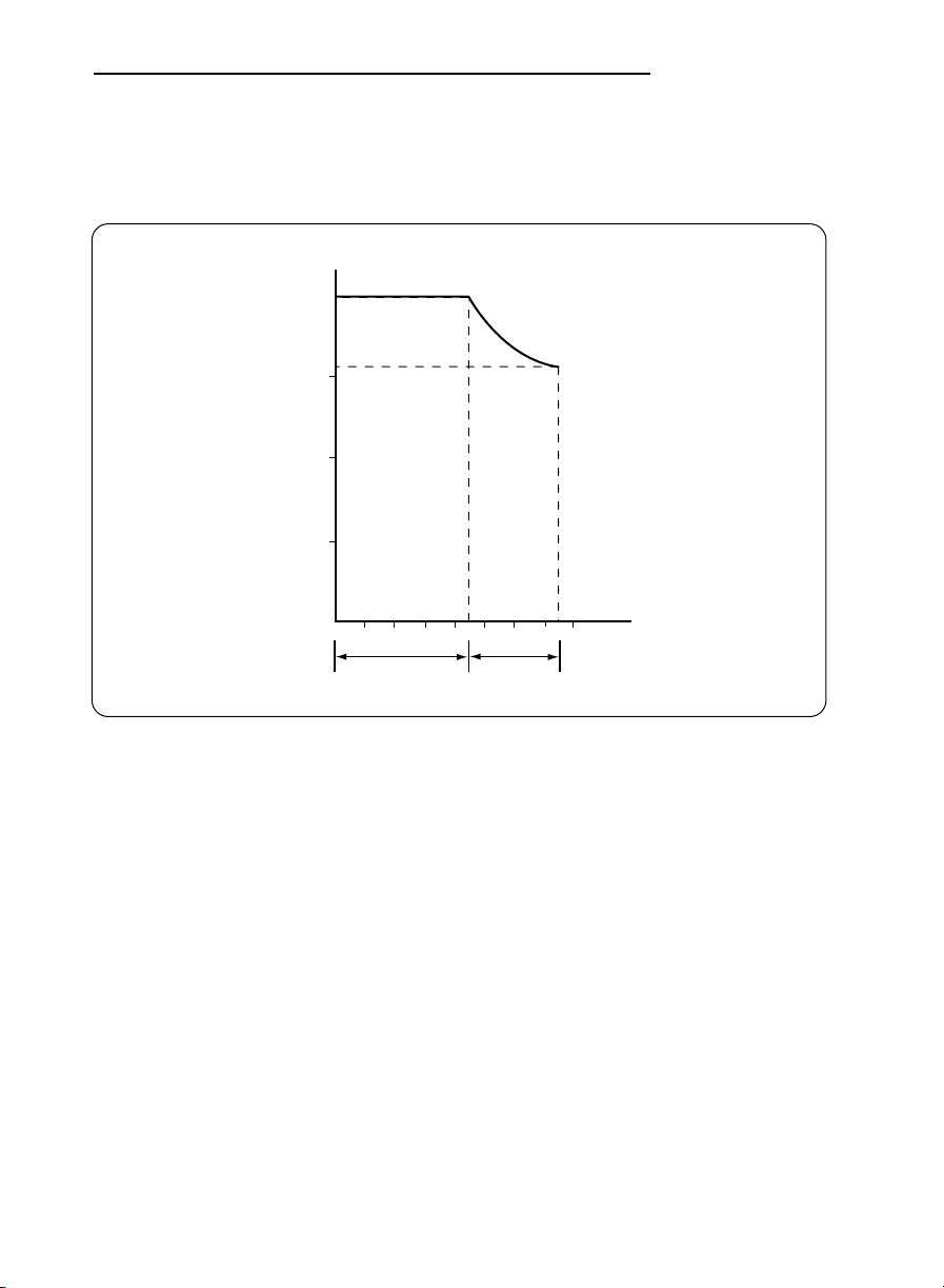
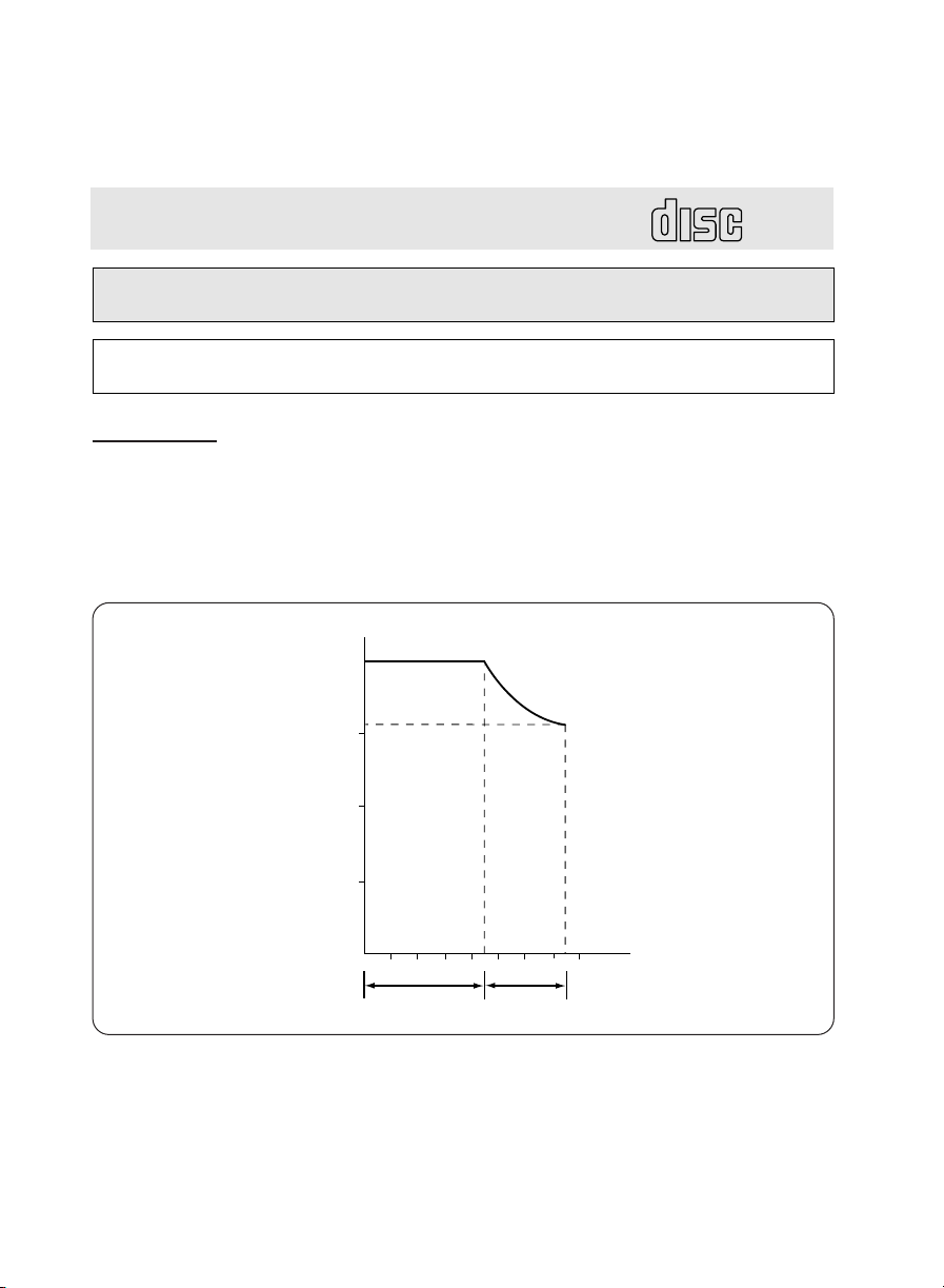
CAV+ CLV : The latest in CD-ROM Disc Rotation Method
0
45
74
3,200
4,000
rpm
Minutes
CAV (8X~16X)
CLV (16X)
Your new 16X CD-ROM drive utilizes a combination of Constant Angular Velocity (CAV) and Constant Linear
Velocity (CLV) disc rotation to achieve the ultimate performance. Previously, CD-ROM drives utilized only CLV
technology to rotate the disc which resulted in a constant data transfer rate by adjusting the CD-ROM's rotation.
In other words, the drive's motor would slow down to read data located on the outer tracks.
However, as transfer rates increased beyond 1.2 Mb/sec (8X), the motor rotation became so fast that it caused
too much vibration and noise. With a combination of CAV and CLV technology, LG Electronics is able to achieve
a maximum transfer rate of 2.4 Mb/sec (16X), speed up the access time to 100ms. At the same time, CAV+ CLV
technology causes considerably less noise and vibration than high speed CLV only CD-ROM drives.
E-3

FEATURES
FEATURES
■ E-IDE interface
■ 100ms average access time
■ Multimedia PC compatible
■ Photo CD multisession support
■ Small CPU bandwidth (MPC spec.)
■ 16X-speed Max 2400KB/sec data transfer rate
■ Intelligent 128KB data buffering system
■ Horizontal/Vertical mounting support
■ Power Disc Loading/Ejection system without caddy
■ Designed for internal mounting
■ Easy audio CD control button support
■ Supports Windows 95 Plug and Play ATAPI protocol
SYSTEM REQUIREMENTS
An IBM PC or compatible with the following system components:
■ IBM Compatible 486SX or above
■ A Minimum of 640K memory
■ Floppy disk drive (3
■ MS-DOS version 3.1 or greater
■ An open, front-facing, half-height drive bay.
■ An existing IDE controller in your PC with an available cable connector or a new
IDE controller that you will install.
1
/2inch)
SUPPLIED ACCESSORIES
Item
Owner's Manual
Setup diskette
Audio Cable
Quantity
1
1
1
E-4
LOCATION AND FUNCTION OF CONTROLS
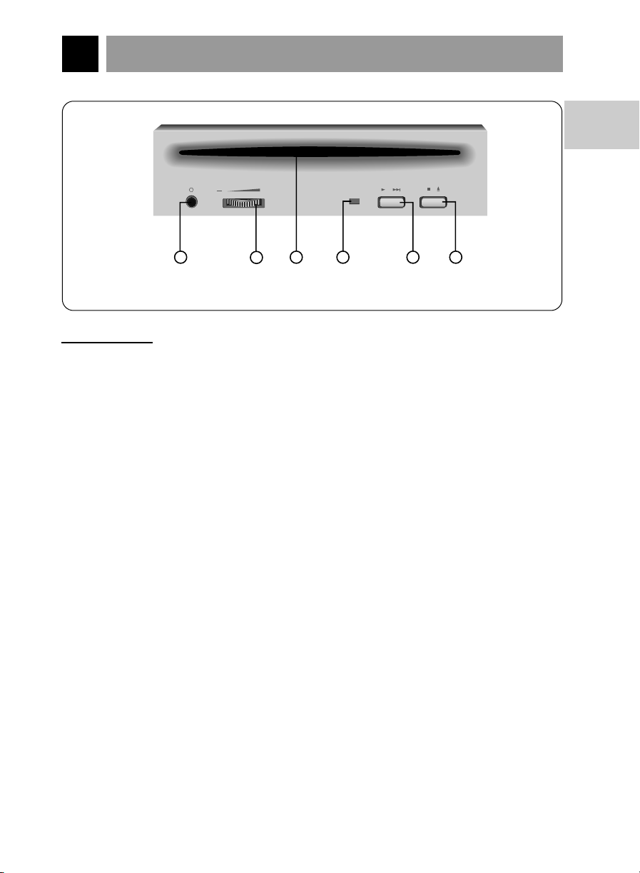
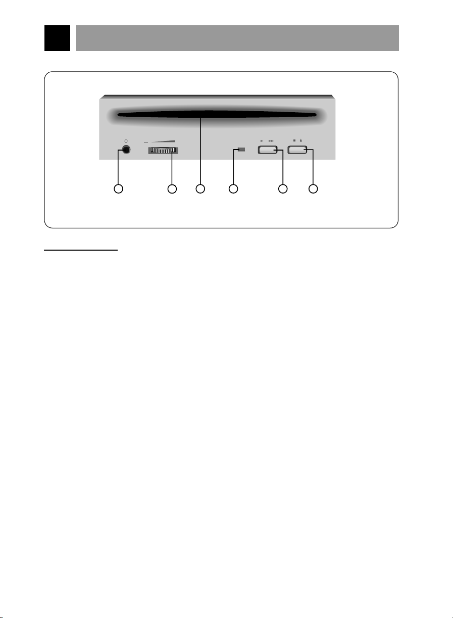
Figure 1. Front View
1
2
54 63
FRONT VIEW
1. Headphone Jack
3.5mm jack for monitoring the audio signal from audio CDs.
2. Headphone Volume Control
Adjusts the headphone sound level.
3. Disc Slot
Push a 12cm CD-ROM disc into slot.
English
4. Busy Indicator
The Busy Indicator lights during initialization and data-read operations.
5. Play/Skip Button
When an Audio CD is in the unit, pressing this button will start playing audio CDs
from the first track. If an audio CD is playing, pressing this button will skip to the
next track.
6. STOP/EJECT Button
This button is pressed to eject the CD disc.
The button works only when power is applied to the drive.
If an audio CD is playing, pressing this button will stop it, and pressing it
will eject the CD disc.
E-5
again
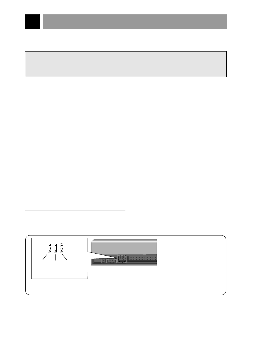
BACK VIEW
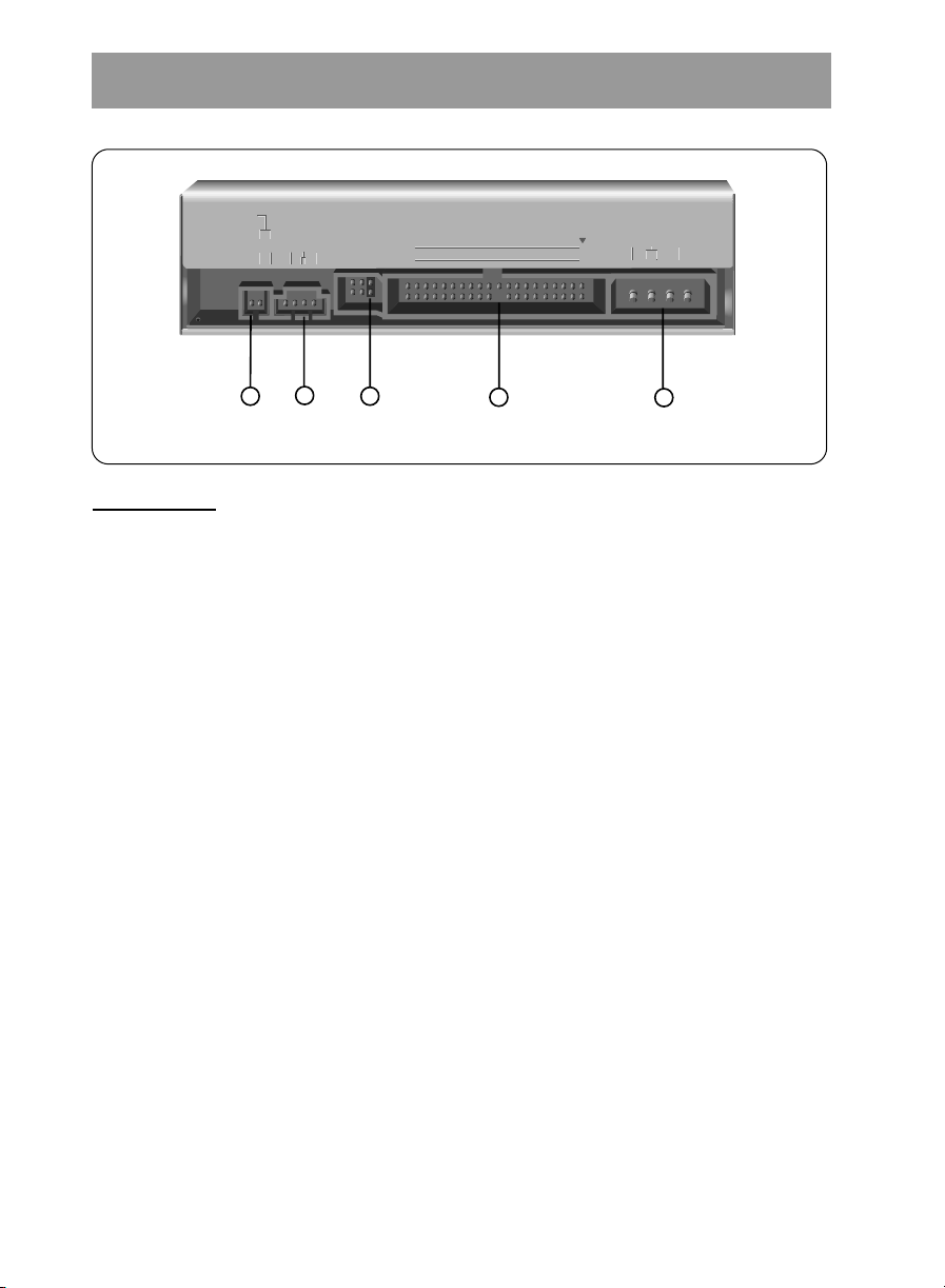
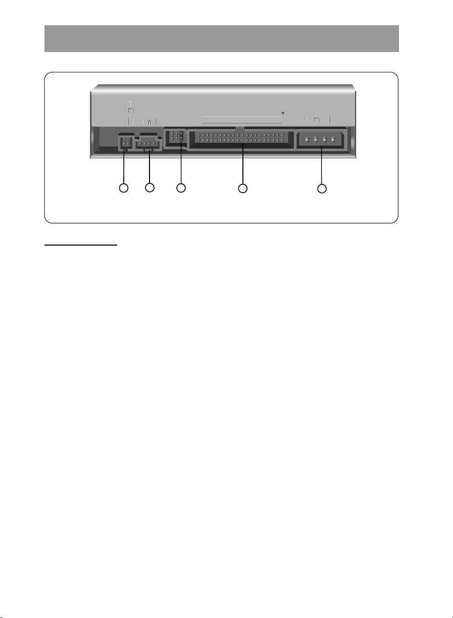
Figure 2. Back View
DIGITAL ANALOG
INTERFACE POWER
DR CSM
SLA
GLG39 1
+5
+12
GND
40 2
AUDIO AUDIO
1
2
5
4
3
1. Digital Audio Ouput Connector
This is a digital audio output connector or Video CD output connector.
You can connect this to the digital audio system or Video CD Board.
2. Analog Audio Output Connector
The Audio Output Connector connects to a sound card.
The supplied audio cable is a SoundBlaster
sound card, you will need to contact the sound card manufacturer to obtain the
proper cable for that card.
3. Master / Slave / CSEL Jumper
These three jumpers are used to set the CD-ROM Drive to either a Master, Slave,
or CSEL drive.
Refer to section HARDWARE INSTALLATION.
4. Interface Connector
This 40-pin connector is used to transfer and control signals between the
CD-ROM Drive and your PC.
Connect the 40-pin IDE cable in your PC to this connector.
5. Power-in Connector
Attach a power cable from the computer to this connector.
®
type cable. If you have a different
E-6
INSTALLATION, USAGE AND HANDLING PRECAUTIONS
■ Installation
Avoid placing the drive in a location subject to :
- high humidity
- high temperature
- mechanical vibration
- direct sunlight
■ Operation
- During operation, excessive vibration or a sudden jolt to the drive may cause a
malfunction.
- Avoid exposing the drive to sudden changes in temperature. This may cause
condensation to collect inside the drive.
■ Transportation
- Always remove the disc before moving the drive.
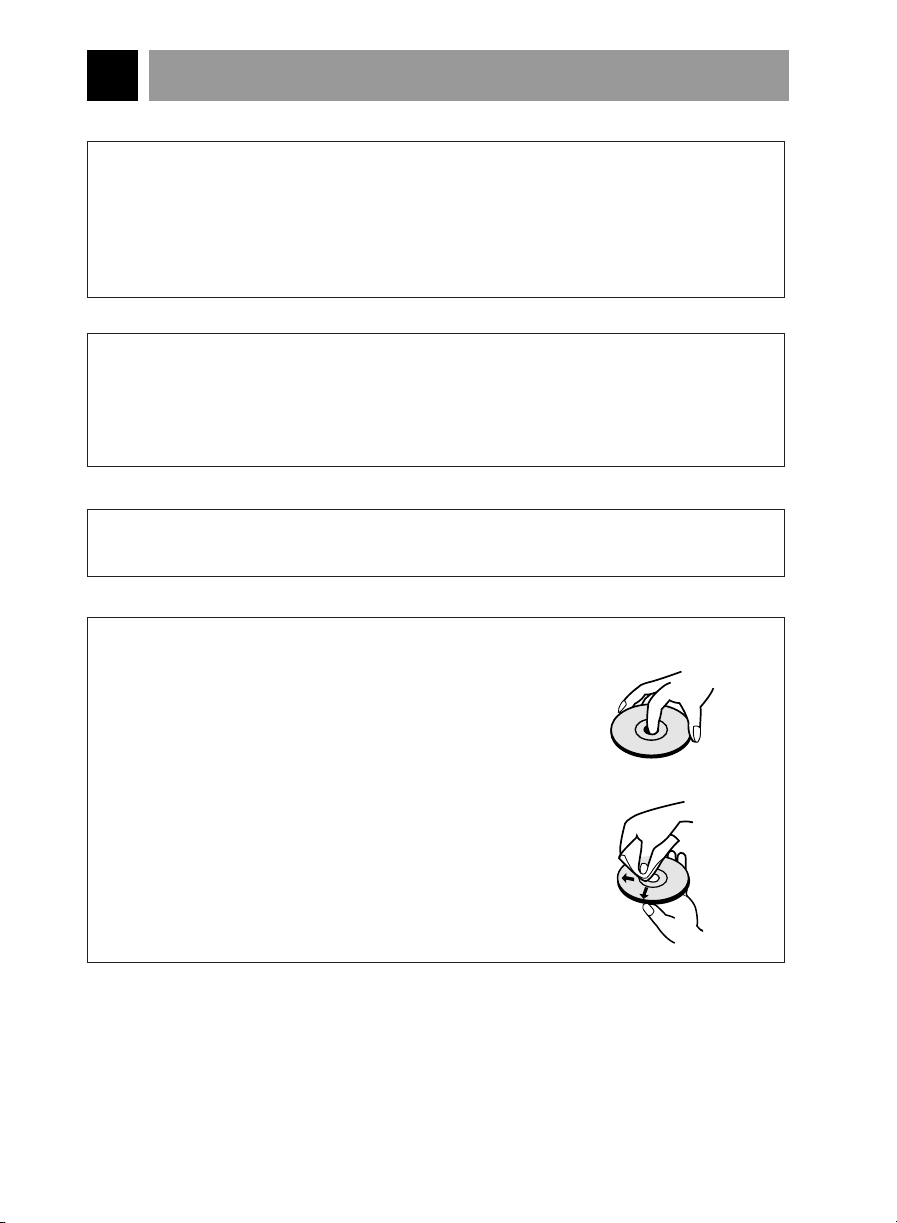
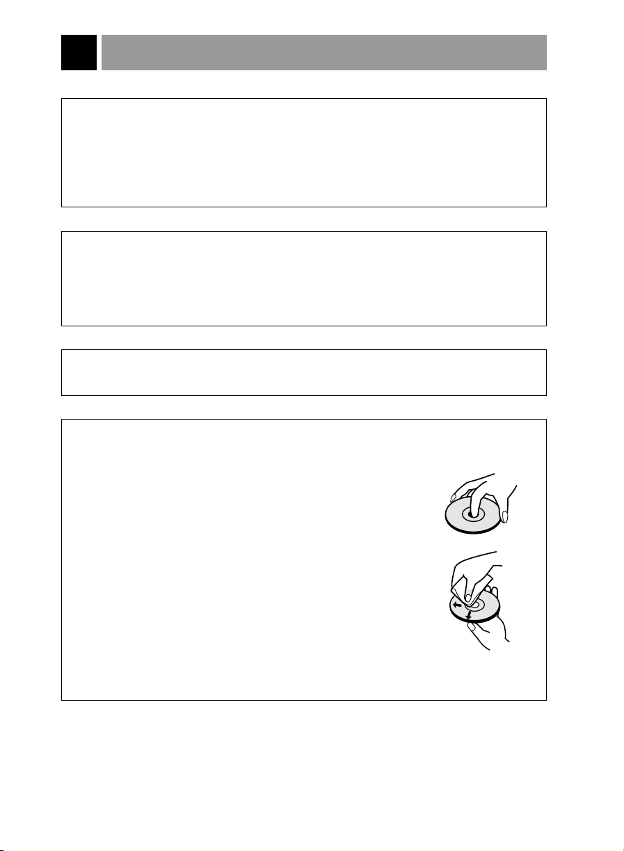
■ Handling CD Discs
- Do not insert 8cm CDs into the unit.
- Do not touch the unlabeled side(data side) of the disc.
If dust or finger prints get on the disc, you may wipe it
with a soft cloth from center to the edge.
- Do not apply paper labels or write on any part of the disc.
- Do not apply benzine, paint thinner, record cleaner or
static repellent to the disc. These can damage the disc.
- Do not place the disc in any environment where it will be
subjected to direct sunlight or high temperatures.
E-7
HARDWARE INSTALLATION
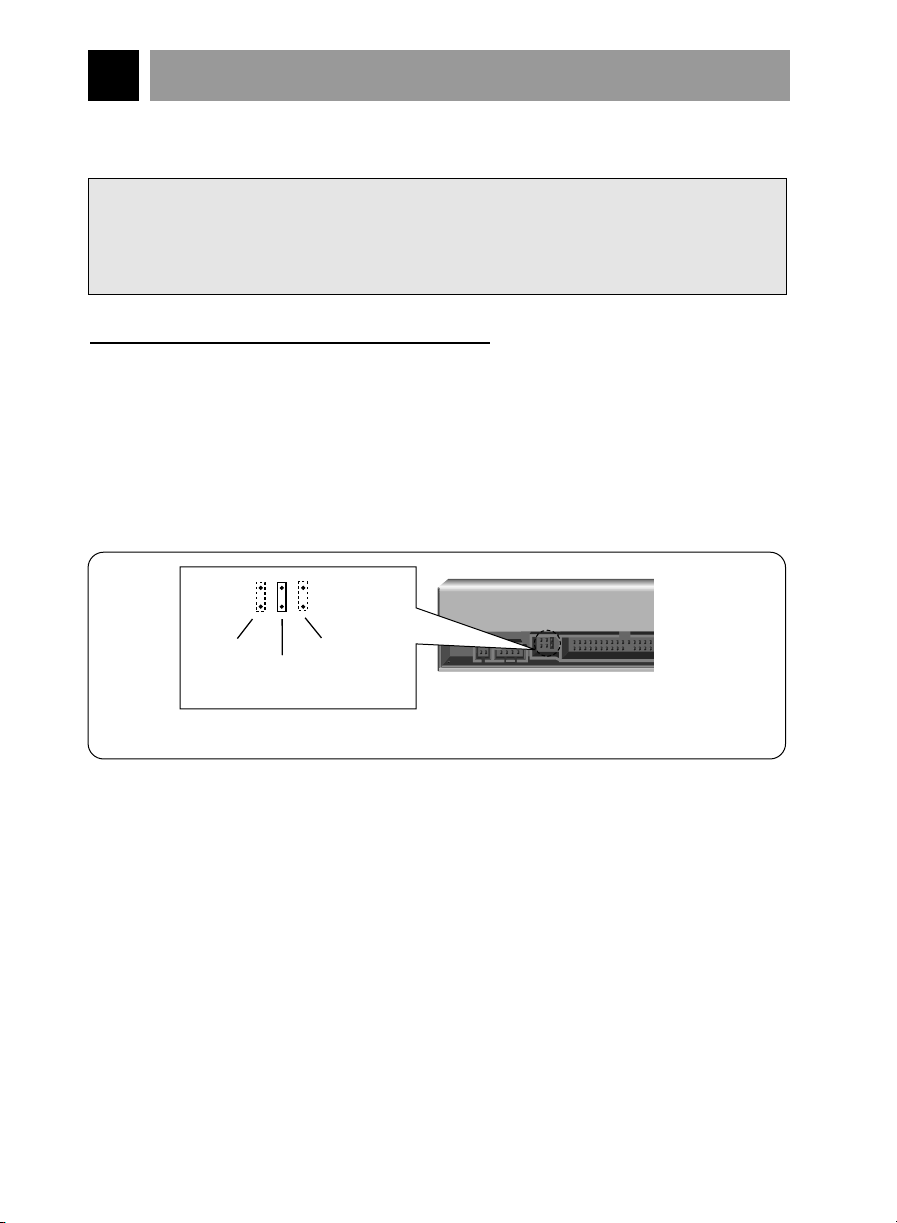
(rear of CD - ROM drive)
Note : The jumper is always
placed vertically,
NEVER SIDEWAYS!
CSEL
mode
SLAVE
mode
(default)
MASTER
mode
Figure 3. Setting MASTER / SLAVE Jumper
This section describes how to install your CD-ROM drive into your computer.
WARNING:
To protect the CD-ROM Drive, your computer, and peripheral devices from damage,
turn off their power before installing the drive.
Note: If you are not comfortable about opening your PC and attempting the CD-ROM
drive installation, many local computer shops can perform this service for a
reasonable cost.
This installation assumes you have a PC with an available connector on an IDE
interface cable. If your PC has an IDE hard drive, there is usually an available
connector in the middle of the same cable that attaches from the motherboard (or
controller card) IDE connector to the hard drive. If the last sentence does not describe
your system, you may need to purchase an IDE controller card to install this CD-ROM
drive. Inspecting and knowing your PC system will make your installation easier and
less time consuming.
A final note before installation: The cable connecting to your floppy disk drive is not an
IDE cable. Do not attempt to attach the CD-ROM drive to this cable.
If the CD-ROM drive is to be connected to the same cable as the hard drive, be sure
that the hard drive is set as master. Hard drives can be set as single, master, or slave.
Check your hard drive owner's manual or contact the hard drive manufacturer for
correct jumper settings.
SETTING MASTER / SLAVE JUMPER
* You will see three pairs of pins and a jumper (cap) at the back of the CD-ROM drive.
This jumper is used to set the CD-ROM Drive as a CSEL, MASTER, or SLAVE device in
your PC. Examples of how the jumper can be placed are shown in Figure 3 below.
* Move the jumper (clip on one pair of pins) from its default factory position (SLAVE), to
CSEL or MASTER as needed (see the following description for the setup that matches
your system), using the above diagram to place the jumper.
E-8
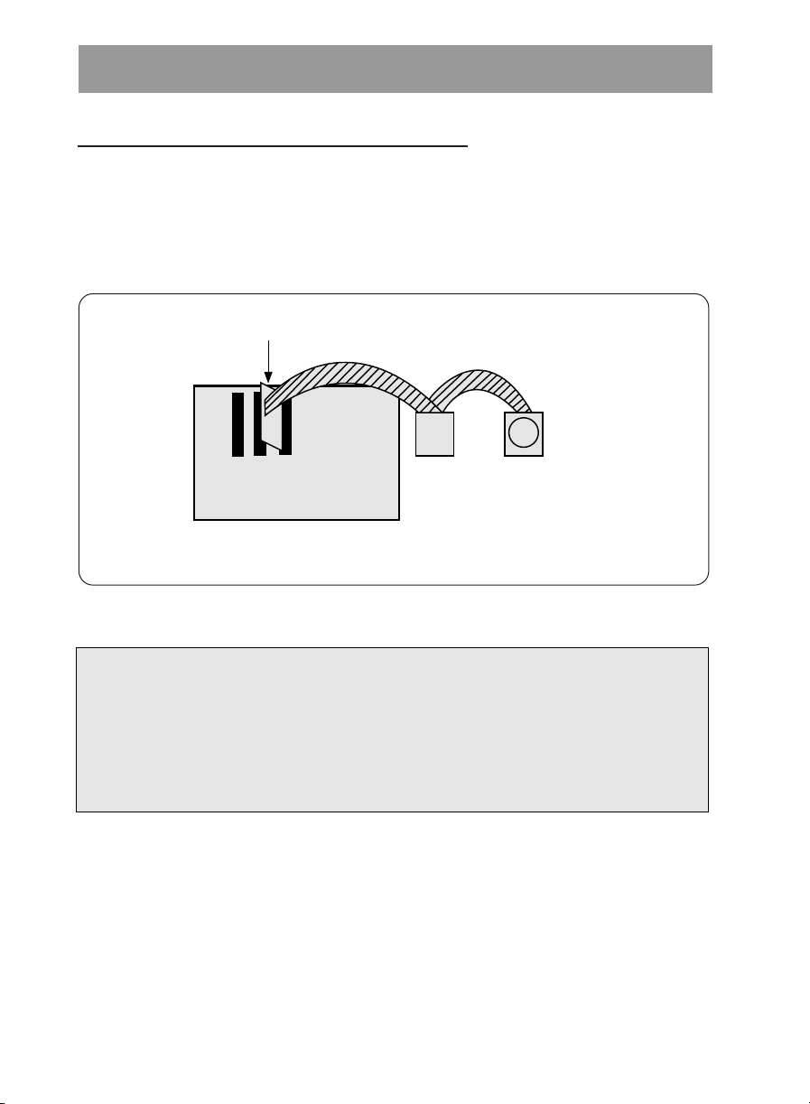
WHEN USING A PRIMARY IDE CONTROLLER
Hard Disk Controller Card
(This card may be a connector on the Motherboard)
Primary IDE Channel
Primary Slave
(Hard Disk or
CD-ROM Drive)
Primary Master
(Hard Disk for
Boot-up)
Card Slot
Motherboard
Figure 4. Primary Controller system Configuration
Most PCs provide one IDE cable to support two devices (one for hard disk, the other for a
second hard disk or a CD-ROM drive). This IDE cable originates either on the motherboard
or on a controller card. This controller is termed the primary IDE controller, and the hard
disk attached that contains the operating system for boot-up is set up as the Primary
Master. Your CD-ROM drive should be set to the Slave mode.
Note:
Many older 1X and 2X CD-ROM drives used a 40 pin controller card that were not
IDE compatible. These were proprietary interface cards for use with a particular
model CD-ROM Drive. Many older Sony, Panasonic, and Misumi drives used 40 pin
proprietary interface cards. If you are upgrading from an older CD-ROM drive, your
new CD-ROM will not work on a proprietary interface card. You will need to buy a
secondary IDE controller card.
E-9
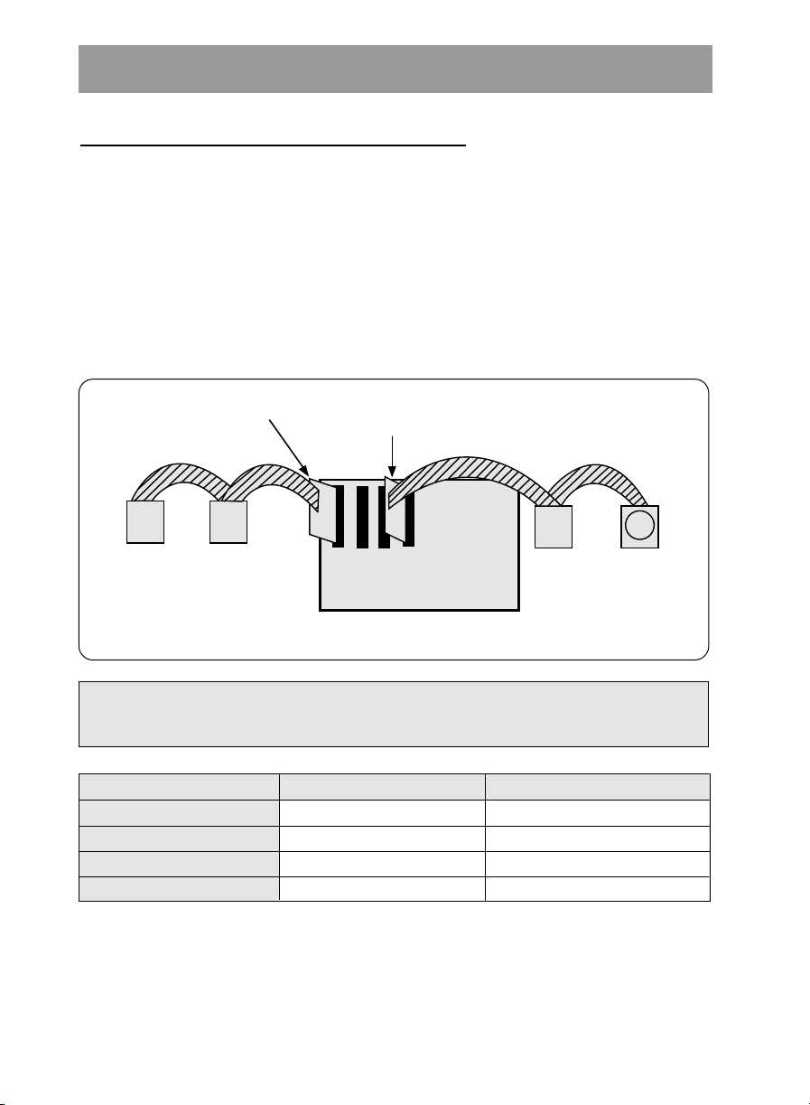
WHEN USING A SECONDARY CONTROLLER
Secondary IDE
Controller CARD
Hard Disk Controller Card
(This card may be a connector on the Motherboard)
Secondary IDE Channel
Primary IDE Channel
Secondary Master
(Hard Disk or
CD-ROM Drive)
Secondary Slave
(Hard Disk or
CD-ROM Drive)
Primary Slave
(Hard Disk or
CD-ROM Drive)
Primary Master
(Hard Disk for
Boot-up)
Card Slot
Motherboard
Figure 5. Possible System Configuration
* If your PC has an additional IDE controller on the motherboard or on a system slot, each
IDE device connected to the secondary IDE controller must also be set to the Master or
Slave mode. If you are connecting your CD-ROM drive to a secondary IDE card, and it is
the 1st device you are connecting to it, then set the CD-ROM jumper to the Master
position. If it is the 2nd device, set the CD-ROM jumper to the Slave position.
* Depending on the IDE card and whether the CD-ROM drive is a master or slave unit,
the diagram below represents the different ways in which the CD-ROM may be
configured in your PC. The table below the diagram shows the possible Jumper
placements that would correspond to each of the different configurations shown.
If you have the system with two IDE channels (in the case of an enhanced IDE PC),
do not install an IDE controller card in your system.
Primary (1st IDE card)
Secondary (2nd IDE card)
Secondary (2nd IDE card)
PC Manual says use CSEL
IDE Controller
CD-ROM Connection
Slave(Hard disk is Master)
Master(1st device on 2nd IDE Card)
Slave(2nd device on 2nd IDE
Card)
E-10
SLAVE (default)
MASTER
SLAVE (default)
CSEL
Jumper Placement
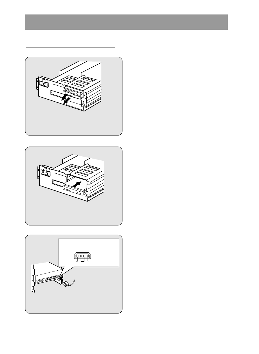
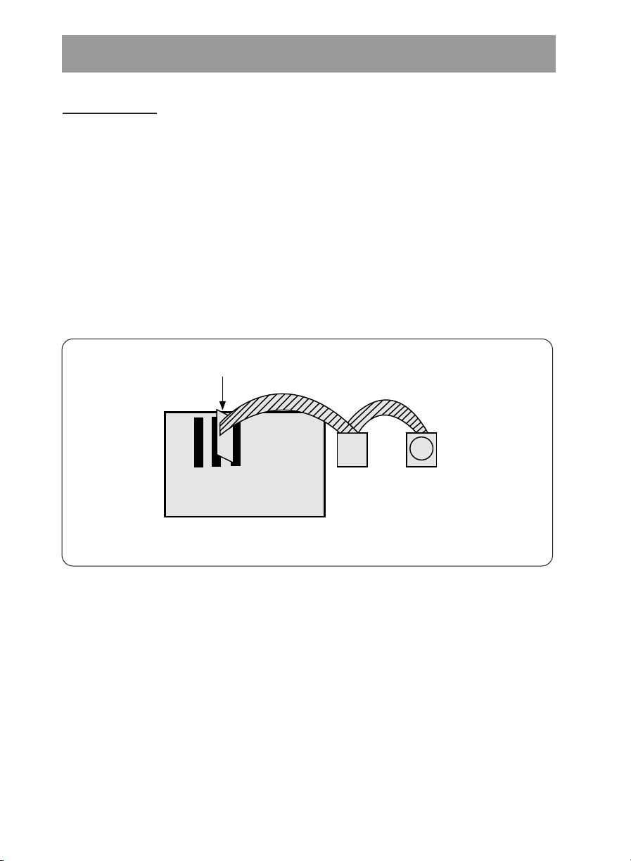
MOUNTING THE CD-ROM DRIVE
Figure 6. Removing the Floppy Disk
Drive and the Blanking plate
Figure 7. Mounting the Drive
Power supply connector
(4-pin connection cable)
Figure 8. Connecting the Power
Supply Cable
GND
Pin assignment
The pin assignment of the power-in
connector is as follows:
12V DC5V DC
Step 1. Turn off and unplug your
computer and all peripheral
devices attached to it.
Step 2. Remove the cover from your
computer.
Step 3. Remove the front panel from an
unused half-height slot.
Step 4. Slide the CD-ROM drive into the
half-height slot, and secure the
drive in place with screws and
brackets.
Note: If there is too much space between
the sides of the drive and the drive
bay, you may need to install spacer
brackets, available at your local
computer store.
Step 5. Push the power supply cable
connector firmly into the power in
connector.
E-11
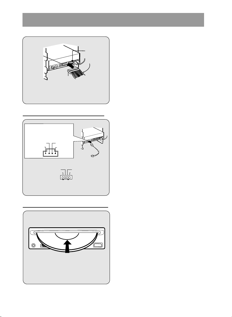
CONNECTING AN AUDIO CABLE
Red-edge
Pin 1
Interface
connector
IDE Cable
Figure 9. Connecting the IDE Cable
to the Interface Connector
L-Channel
GNDGND
R-Channel
* Pin assignment of the audio cable
to Audio
Equipment
(sound card)
Audio
Cable
L-Channel
GNDGND
R-Channel
Pin assignment
The pin assignment of the
audio output connector is
as follows.
Figure 10. Connecting an Audio Cable
to the Audio Output Connector
Insert CD label side up
Note : Use only standard 12cm discs.
Step 6. Connect the 40-pin IDE Cable to
the back of the CD-ROM Drive.
Please make sure that the red
edge of the IDE Cable is
connected to Pin 1 on the CDROM Drive.
If you want to connect audio equipment or
a sound card to the CD-ROM drive, use
an audio cable to connect the drive to the
sound device.
Inserting and Removing a CD Disc.
To insert a CD disc in your CD-ROM
drive, power on your system and:
1. Push a CD disc into the slot with the label
side facing up.
2. Press STOP/EJECT button to eject CD
disc from slot.
• Do not touch the unlabeled side of the
disc.
E-12

SOFTWARE SET UP
THE SET UP PROCESS
The INSTALL program performs the following functions.
* Allows the user to select the target disk drive where CD-ROM device driver files will
be set-up.
* Unless modified by the user, the INSTALL program searches the target disk for
directory(\CDROM); if it is not found, the directory(\CDROM) is created.
* Copies the CD-ROM device driver file named GSCDROM.SYS, the Microsoft CD-ROM
Extension file named MSCDEX.EXE, and the utility files to the specified directory.
* Modifies your CONFIG.SYS file to list the location and name of the device driver.
* Modifies your AUTOEXEC.BAT file to load MSCDEX.
* Terminates and returns control to the user.
LIST OF FILES TO BE INSTALLED IN YOUR PC
❊ MSCDEX.EXE Microsoft MS-DOS CD-ROM Extension software, which
enables the computer to access the CD-ROM drive.
❊ GSCDROM.SYS CD-ROM device driver.
❊ EJECT.EXE Software eject program which can eject the CD.
❊ LOCK.EXE Program which disables the Eject Button.
The Eject Button will not function in the locked state.
The lock function is useful when you are using the
CD-ROM drive for important work.
❊ UNLOCK.EXE Program which enables Eject Button.
Eject Button will function properly after executing the
unlock program.
E-13

RUNNING THE INSTALL PROGRAM (DOS INSTALLATION)
Step 1. Insert the CD-ROM device driver install diskette into the appropriate drive.
Step 2. Go to the floppy drive by typing A: or B: at the DOS prompt, as appropriate.
Step 3. Type the word INSTALL and press [ENTER].
Step 4. The INSTALL program will begin loading. When loading is complete, the
INSTALL program identification will appear on the screen.
Step.5. Follow the instructions on the screen.
Step 6. If you specify the path information during the installation, the install program will copy
the CD-ROM device driver file named GSCDROM.SYS, the Microsoft CD-ROM
Extension file named MSCDEX.EXE and the utility files to the specified directory,
and modify your CONFIG.SYS file and AUTOEXEC.BAT file.
Step 7. When the installation is completed, remove the diskette, and reboot your PC.
CD-ROM EXTENSION PROGRAM MSCDEX. EXE OPTIONS
There are several options that are set for the Microsoft CD Extension program.
Generally, these settings do not have to be changed for the CD-ROM drive to work, so
these options are needed no further. However, you may decide to change the MSCDEX
option settings depending on your operating environment.
These options are explained below:
PARAMETER
/D (Device Name)
/E
/L: (Device Name)
/M: (Value)
/V
DESCRIPTION
Tells MSCDEX.EXE what the device driver
(must be same as was used in "/D:" expression of
"DEVICE=" line in CONFIG.SYS file)
Tells MSCDEX.EXE to use expanded memory
Indicates the drive letter to be assigned to the CD-ROM
drive
Tells MSCDEX.EXE how much memory to allocated for
caching. Default is 10 (represents 10 kilobytes).
Provides memory usage statistics, such as how much
memory is used by buffers, resident data, and resident
code.
E-14
¡fls name is

ATAPI Installation (Windows 95 and others)
* For Windows 95 installation, do not use the installation diskette supplied. This CD-
ROM drive is Windows 95, Windows NT 3.5, and OS/2 Warp compatible, generally
utilizing the generic software drivers supplied with those operating systems Below is
the example installing the driver for Windows 95. For other operating systems, try
looking for either a LG Electronics or Goldstar IDE CD-ROM drive software driver. If
none is found, try selecting one of the device drivers for
(For Windows 95)
1. Install the CD-ROM drive in your PC as described in this manual.
2. Power up your PC. Upon starting Windows 95, it might automatically detect the new
CD-ROM drive and load the driver software for it. If not, proceed to the next step.
3. In Windows 95, Click on the Start button. Click on the Settings button. Click on the
Control Panel button. Double-Click on the Add New Hardware icon. Follow the
instructions for the computer to search your system for new hardware. It will locate
the CD-ROM drive and load the generic driver.
Non-listed IDE CD-ROM .
TROUBLESHOOTING
* When the CD-ROM drive does not work with the hard disk drive in primary
IDE channel.
(SOLUTION)
1. Check the CD-ROM drive Master/Slave Jumper setting.
The CD-ROM drive must be set to the Slave mode.
2. Check to be sure your hard disk Interface type is IDE type.
3. Check your hard disk Master/Slave Jumper setting.
Some old-version IDE type hard disks were set to Master Only mode.
In that case, contact your hard disk company and change your hard disk jumper
setting to master mode.
4. If the CD-ROM drive does not work with above methods, you may need a secondary
IDE card. If you use the secondary IDE card, you should set the CD-ROM drive
jumper to the master mode if the CD-ROM drive is the first device you are
connecting to the secondary IDE card.
* When the CD-ROM drive does not install in OS/2 warp.
(SOLUTION)
1. Select
NON-LISTED IDE CD.
* CD-ROM drive is not present in Windows 3.1 or 3.11 or DOSSHELL.
(SOLUTION)
1. When the WTN or DOSSHELL command lines are present in your AUTOEXEC.BAT,
make sure that the MSCDEX.EXE command line appears before the WIN or the
DOSSHELL command lines.
E-15
SPECIFICATIONS
General
Data Capacity 553 Mbyte (mode 1), 635 Mbyte (mode 2)
Disc Diameter 12 cm only
Rotational Speed 200 - 4,200 rpm
Performance
Interface E-IDE
Supported System IBM PC-AT or Compatible
Transfer rate Sustained Data Transfer Rate = Max 2400Kbytes/sec
Access Time Average100 ms (1/3 Stroke)
MTBF 125,000 Power On Hours (Duty Cycle 10%)
Buffer size 128 Kbytes
Error Rate
ECC on 1block/10
ECC off 1block/10
User Data/Block 2,048 bytes/block (Mode1 & Mode2 Form1)
2,340, 2,336 bytes/block (Mode2)
2,324 bytes/block (Mode2 Form2)
2,352 bytes/block (CD-DA)
Supported Disc CD-DA, CD-ROM, CD-ROM XA-READY, Photo-CD
Audio Specifications
Frequency Response 100 Hz - 20 kHz +1/-3 dB
Dynamic Range 80 dB
S / N Ratio 85 dB
THD 0.01 % at 1 KHz
Channel Separation 80 dB at 1 KHz
Headphone Level 0.60 Vrms (33Ω)
Line Output Level 0.70 Vrms +
Line Output Jack 4 Pin terminal (Rear)
Headphone Jack ø 3.5 mm (Front)
15
bits(single), 1 block/1012bits (16x)
12
bits(single), 1 block/109bits (16x)
20 % (47kΩ)
Environment
Temperature 5 - 45
°C
Power Requirements
12 V + 10%
Ripple < 100m Vpp
5%
5 V +
Ripple < 100m Vpp
NOTE: Specifications are subject to change without notice for improvement.
1.0A (Maximum)
0.6A (Maximum)
E-16

Deutsch
CD-ROM LAUFWERK
BEDIENUNGSHANDBUCH
MODELL : CRD-8161B
Um alle Möglichkeiten und Funktionen lhres CD-ROM Laufwerkes voll
ausschöpfen zu können, lesen Sie bitte dieses Bedienungshandbuch
aufmerksam und völlständig.
Achtung: Um die Gefahr eines elektrischen Schlages zu vermeiden, entfernen Sie nicht das Gehäuse.
COMPACT
0
45
74
3,200
4,000
rpm
Minutes
CAV (8X~16X)
CLV (16X)
Keine durch den Anwender zu reparierende Teile im lnnern.
Überlassen Sie den Service qualifiziertem Service-Personal.
Da der im CD-ROM Laufwerk benutzte Laser gefährlich für die Augen ist, sollten Sie keineswegs
versuchen, das Gehäuse zu öffnen.
Lassen Sie den Service nur durch qualifizierte Servicestellen durchführen.
Dieses Laufwerk ist kompatibel zu CD-ROM Disk
mit diesem Warenzeichen.
Warnung: Um die Gefahr eines Feuers oder eines elektrischen Schlages zu
vermeiden, setzen sie dieses Gerät niemals Regen oder Feuchtigkeit aus.
Dieses Produkt entspricht der EMC Richtlinie 89/336/EEC und ist
demnach mit dem CE Label gekennzeichnet.
CAV+ CLV :
Ihr neues 16fach CD - ROM Laufwerk nutzt eine Kombination von CAV = Constant Angular Velocity (Konstante
Winkelgeschwindigkeit) und CLV = Constant Linear Velocity (Konstante Linear Geschwindigkeit)
Steuerungstechnik für den Disc Antrieb, um beste Abtastergebnisse zu erreichen.
Herkömmliche Laufwerke setzten für den Antrieb der Disk ausschließlich CLV Technik ein, was durch Anpassung
der Drehgeschwindigkeit zu einer gleichbleibenden Datenübertragungsleistung führt.
Mit anderen Worten, der Antriebsmotor reduziert die Drehgeschwindigkeit, um die Spuren am äußeren Rand zu
lesen.
Dennoch wurde die Umdrehungsgeschwindigkeit bei Datenübertragungsraten größer als 1,2MB/sec. = 8fach so
schnell, daß zu viel Vibration und Geräusch entstand.
Durch die Verbindung von CAV und CLV Technik ist das Laufwerk von LG Electronics in der Lage, eine
maximale Datenübertragungsrate von 2,4MB/sec 16fach zu erreichen, bei einer Zugriffszeit von 100ms.
Gleichzeitig führt die kombinierte Verwendung von CAV und CLV Technologie zu viel geringeren Vibrationen und
Geräusch als die früheren CD - ROM Drives, die ausschließlich CLV Technik einsetzen.
D-2

PRODUKTMERKMALE
PRODUKTMERKMALE
■ Enhanced - IDE Interface
■ 100 ms mittlere Zugriffszeit
■ Multimedia PC kompatibel
■ Multisession Photo CD fähig
■ geringe CPU Belastung (gemäß MPC Spezifikationen)
■ 16fach Datentransferrate
■ intelligente Datenbufferung
■ HIFI Audioausgabe
■ Motor Lade/Auswurf System ohne Caddy
■ zum internen Einbau vorgesehen
■ Einfache Handhabung durch Audio CD Bedienungstaste
SYSTEMVORAUSSETZUNGEN
Ein IBM TMPC TMkompatibles System mit folgenden Komponenten:
■ IBM kompatibles System mit min. 486 SX oder höher
■ mindestens 640 k Speicher
■ 3.5" Floppy Diskettenlaufwerk
■ MS-DOS Version 3.1 oder größer
* MITGELIEFERTES ZUBEHÖR
Bezeichnung
Bedienerhandbuch
Installationsdiskette
Audiokabel
IDE Controller Karte
Interface Kabel
Menge
1
1
1
1 (Optional)
1 (Optional)
D-3
LAGE UND FUNKTION DER BEDIENELEMENTE
Abbildung 1. Frontansicht
1
2
54 63
FRONTANSICHT
1. Kopfhörerbuchse
3.5 mm Klinkenbuchse zum Mithören des Audiosignals
2. Kopfhörerlautstärkeregler
Regulieren Sie die Lautstärke der Kopfhörer
3. CD-Ladeschacht
Schieben Sie eine 12 cm CD-ROM in diese Offnung.
4. Betriebs-LED
Die Betriebs LED leuchtet während der Initialisierung und während des Lesens
von Daten.
5. Wiedergabe/Überspringen Taste
Wenn sich eine Audio CD im Ladeschacht befindet, wird sie auf Tastendruck vom
ersten Stück an abgespielt. Auf erneuten Tastendruck wird das nächste Stück
abgespielt.
6. Stop/Auswurf Taste
Auf Tastendruck wird die CD wieder ausgeworfen.
Die Taste funktioniert nur, wenn das Laufwerk an eine Stromversorgung
angeschlossen ist.
Bei Abspielen einer Audio CD wird diese per Tastendruck angehalten. Auf
erneuten Tastendruck wird die CD ausgeworfen.
D-4
RUCKANSICHT
Abbildung 2. Rückansicht
DIGITAL ANALOG
INTERFACE POWER
DR CSM
SLA
GLG39 1
+5
+12
GND
40 2
AUDIO AUDIO
1
2
5
4
3
1. Digitaler Audio Ausgang
Dies ist ein digitaler Audio Ausgang bzw. Video-CD Ausgang.
Hierdurch können Sie eine Verbindung zum digitalen Audio System bzw. zur
Video-CD Schnittstellen-Karte (z.B. MPEG) herstellen.
2. Audioausgangbuchse
Dieser Steckverbinder dient der Verbindung mit Ihrer Soundkarte
3. Master/Slave/CSEL Jumper
Diese drei Jumper werden dazu benutzt das CD-ROM Laufwerk in den
"Master", "Slave" oder "CSEL" Modus zu setzen.
Lesen Sie hierzu Kapitel "Hardwareinstallation"
4. Interface Anschluß
Dieser 40 polige Steckverbinder wird zur Signalübertragung zwischen dem CDROM Laufwerk und Ihrem PC benutzt. Verbinden Sie das 40 polige IDE - Kabel
Ihres PC mit diesem Steckverbinder. Wenn Sie eine zweite IDE - Karte benutzen,
verbinden Sie diese Steckverbindung mit der zweiten IDE - Karte.
5. Spannungseingangbuchse
Stecken Sie das Stromversorgungskabel Ihres Computers in diese Steck-
verbindung.
D-5
WARTUNG
Installation
■
Vermeiden Sie es das Laufwerk folgenden Umgebungsbedingungen auszusetzen:
- hohe Luftfeuchtigkeit
- hohe Temperatur
- mechanische Erschütterungen
- direktes Sonnenlicht
■ Benutzung
- Starke Vibrationen oder plötzliche Stöße während des Betriebes können
zu einer Fehlfunktion des Laufwerkes führen.
- Vermeiden Sie es das Laufwerk plötzlichen Temperaturwechseln auszusetzen.
Dies würde zu Kondenswasserbildung im Inneren des Laufwerkes führen.
■ Transport
- Entfernen Sie vor einem Transport immer die Disc.
■ Umgang mit CD Disks
- Benutzen Sie keine 8 cm CD-ROM.
- Die Oberseite (Datenseite) der Disk darf nicht berührt
werden. Fingerabdrücke oder Staub auf der Disk können
mit einem weichen Tuch von innen nach außen
abggewischt werden.
- Schreiben Sie niemals auf die Disk und kleben Sie auch
keine Beschriftungsetiketten auf die Disk.
- Reinigen Sie die Disk auf keinen Fall mit Benzin,
Verdünner, Schallplattenreiniger oder Anti-Statik-Lösung.
Die Disk kann dadurch zerstört werden.
- Bewahren Sie die Disk nicht an Orten auf, wo sie durch
direkte Sonneneinstrahlung oder hohe Temperaturen
zerstört werden könnte.
D-6
HARDWAREINSTALLATION
Abbildung 3. Konfigurationsjumper
CSEL
SLAVE
MASTER
(Standardeinstellung)
Dieser Abschnitt beschreibt den Einbau des CD-ROM Laufwerkes in Ihren Computer.
Warnung:
Um das CD-ROM Laufwerk und Ihren Computer, sowie Peripheriegeräte vor
Beschädigungen zu schützen, ziehen Sie den Netzstecker, bevor Sie das Laufwerk
einbauen.
SETZEN DES MASTER / SLAVE JUMPERS
* Auf der Rückseite des CD-ROM Laufwerkes sehen Sie drei Jumper.
Diese Jumper werden benutzt um das CD-ROM Laufwerk in den "CSEL",
"MASTER" oder "SLAVE" Modus zu setzen. Der Jumper muß in eine der drei
möglichen Positionen gesteckt werden.
Wenn der Jumper auf die "CS" Position gesetzt wird, sollte das Laufwerk das
CSEL Signal des Hostadapters zur Konfigurierung benutzen.
Die Jumper auf der Rückseite des Laufwerkes sollten nach Einbau zugänglich
bleiben.
D-7
BEMERKUNG:
Festplattencontrollerkarte
(Diese Karte kann sich auch als Anschlu auf dem Motherboard befinden)
Erster IDE-Anschluß
Primary Slave
(Hard Disk or
CD-ROM Drive)
Primary Master
(Hard Disk for
Boot-up)
Card Slot
Motherboard
Abbildung 4. Mögliche Systemkonfiguration
Die meisten PC's unterstützen über einen Anschluß zwei Geräte (eine Festplatte, und
ein CD-ROM Laufwerk oder eine zweite Festplatte). Dieser IDE Anschluß befindet sich
entweder auf dem Motherboard oder auf einer Steckkarte.
Dies ist der erste (primary) IDE Adapter.
Falls das Betriebssystem von der Festplatte geladen wird, muß diese in den Master
Mode gesetzt sein und somit das CD-ROM Laufwerk in den Slave Modus gesetzt
werden.
* Wenn Ihr PC über einen zusätzlichen zweiten (secondary) IDE Controller auf dem
Motherboard oder auf einer Steckkarte verfügt, so muß jedes der an diesen zweiten
Controller angeschlossenen Geräte ebenfalls entweder in den Master oder den
Slave Mode gesetzt werden. In diesem Fall kann Ihr System vier Geräte
unterstützen: Primary Master, Primary Slave, Secondary Master, Secondary Slave.
D-8
 Loading...