

Lg Cp06g10, Cp08g10 Owner's Manual
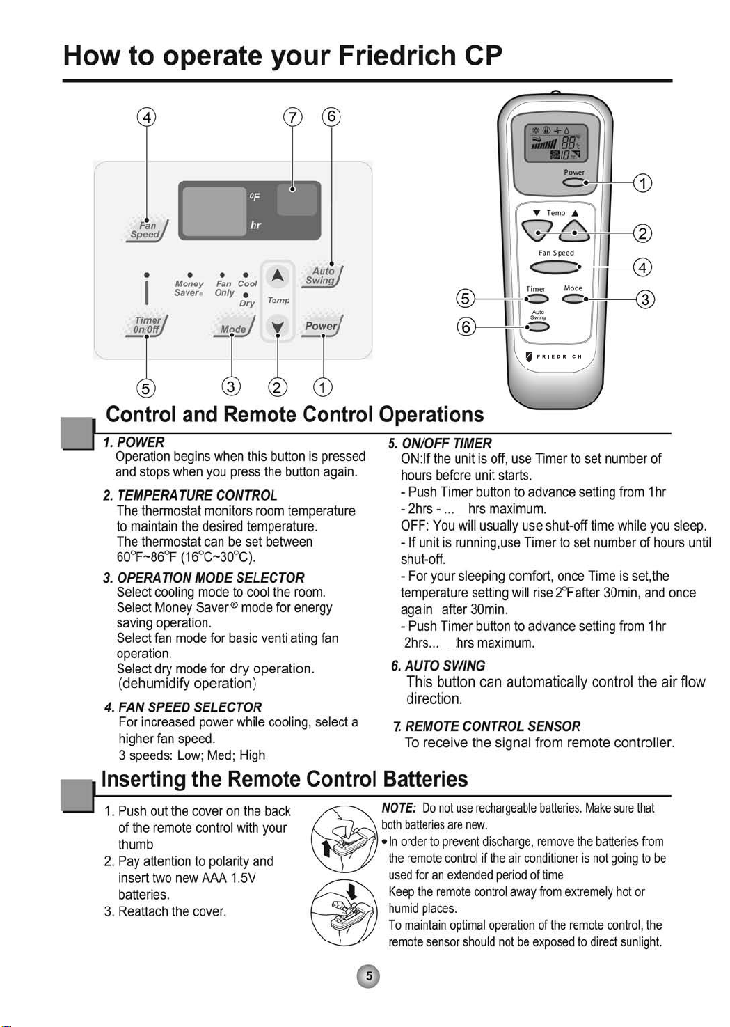
Power
Mode
Timer
0n/0ff
Fan
Speed
Temp
CoolMoney
Saver
®
Fan
Only
Dry
hr
Auto
Swing
06 CP08
Power
Mode
Timer
0n/0ff
Fan
Speed
Temp
CoolMoney
Saver
®
Fan
Only
Dry
hr
Auto
Swing
CP
0
F
0
0
F
F
hr
Fan
Speed
Auto
Swing
CoolMoney
Fan
Saver
Only
®
Temp
Dry
Timer
Power
Mode
0n/0ff
200

Congratulations! Thank you for choosing
Friedrich.
Your Friedrich unit is designed for
maximum comfort and quietness.
Table of Contents
Introduction ..................................................................................2
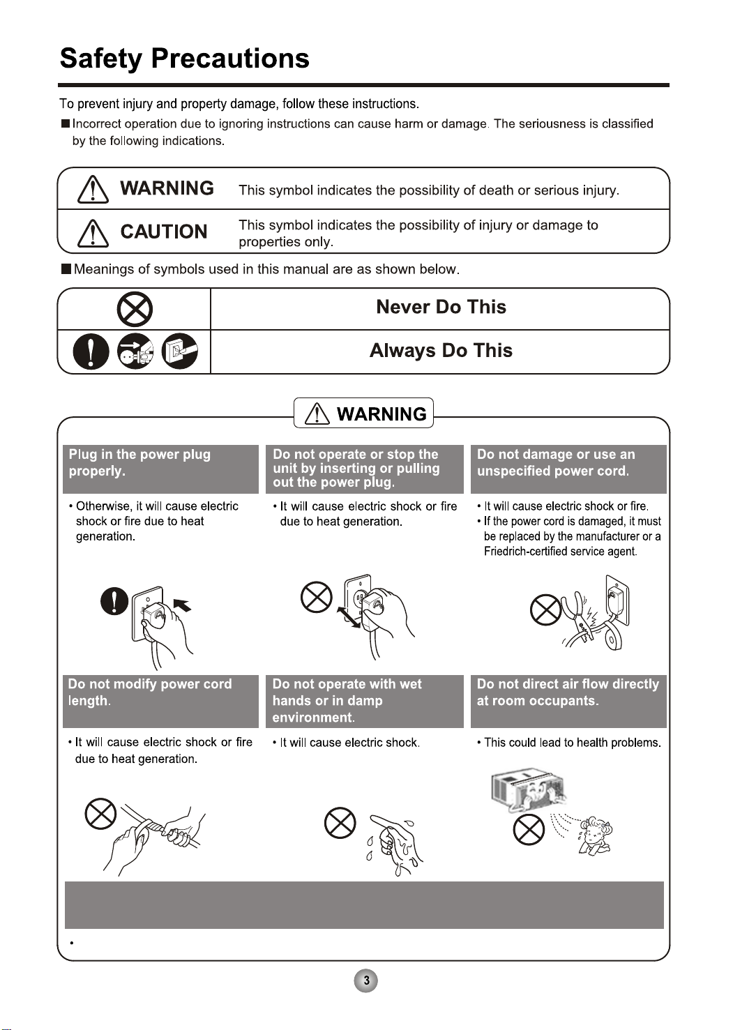
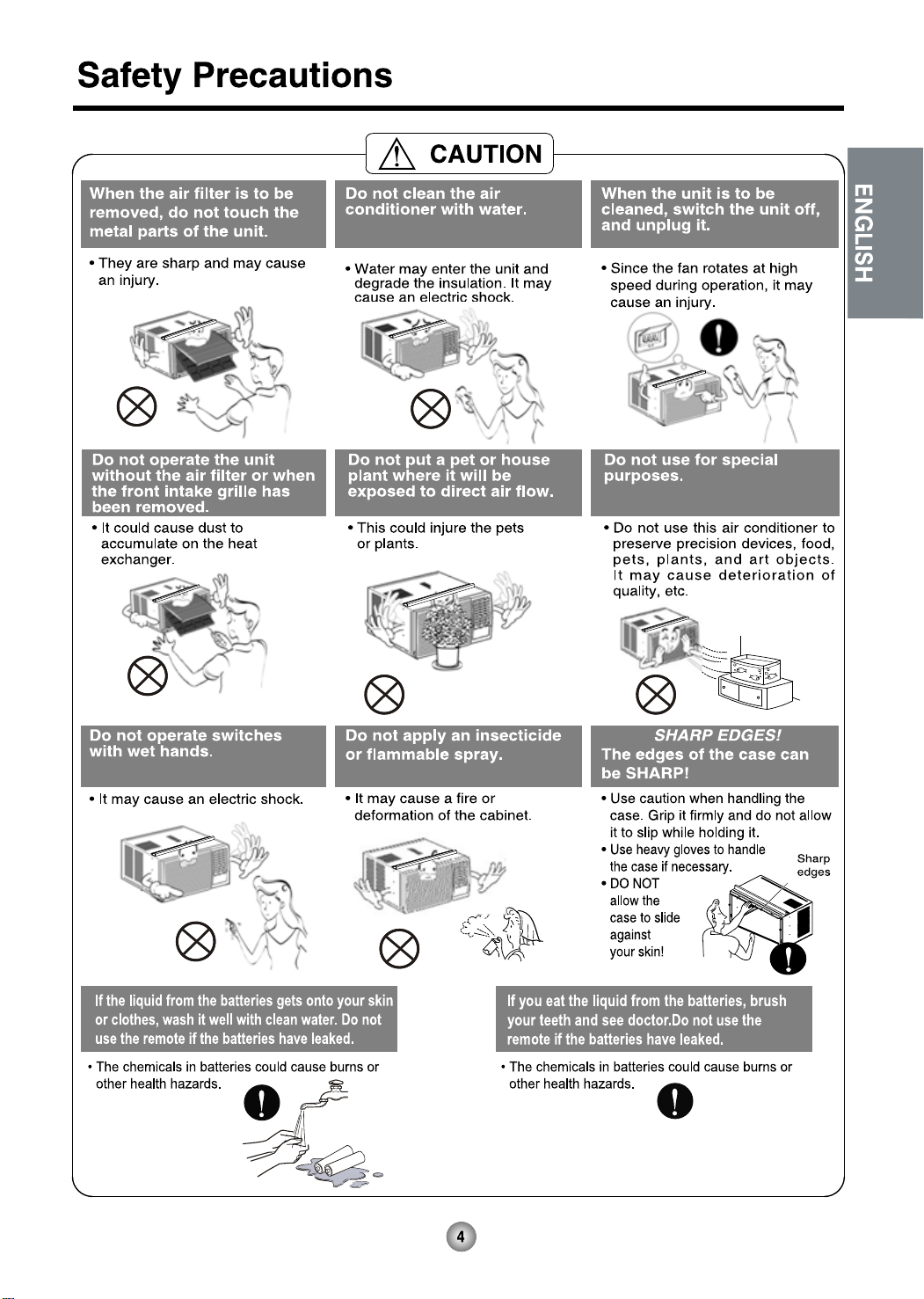
Safety Precautions.......................................................................3
How to operate your Friedrich ...................................................5
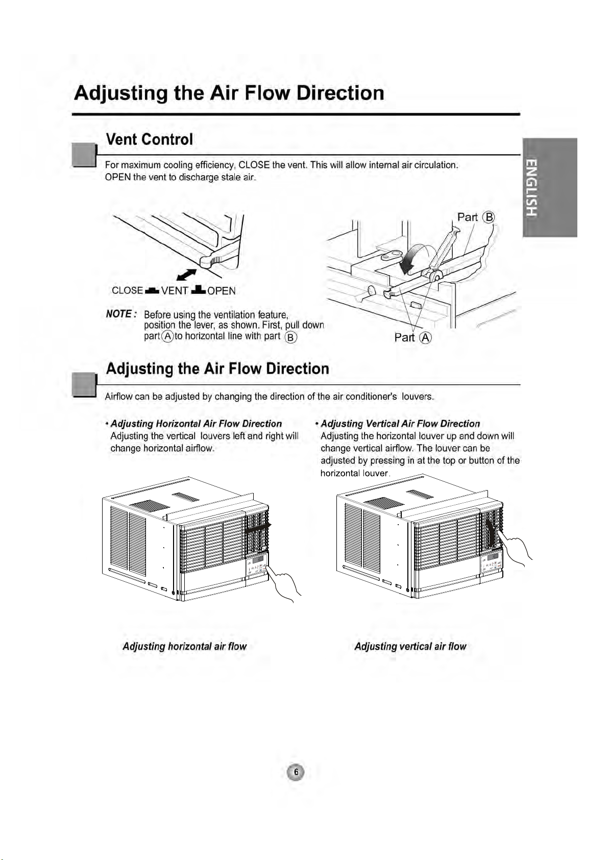
Adjusting the Air Flow Direction.................................................6
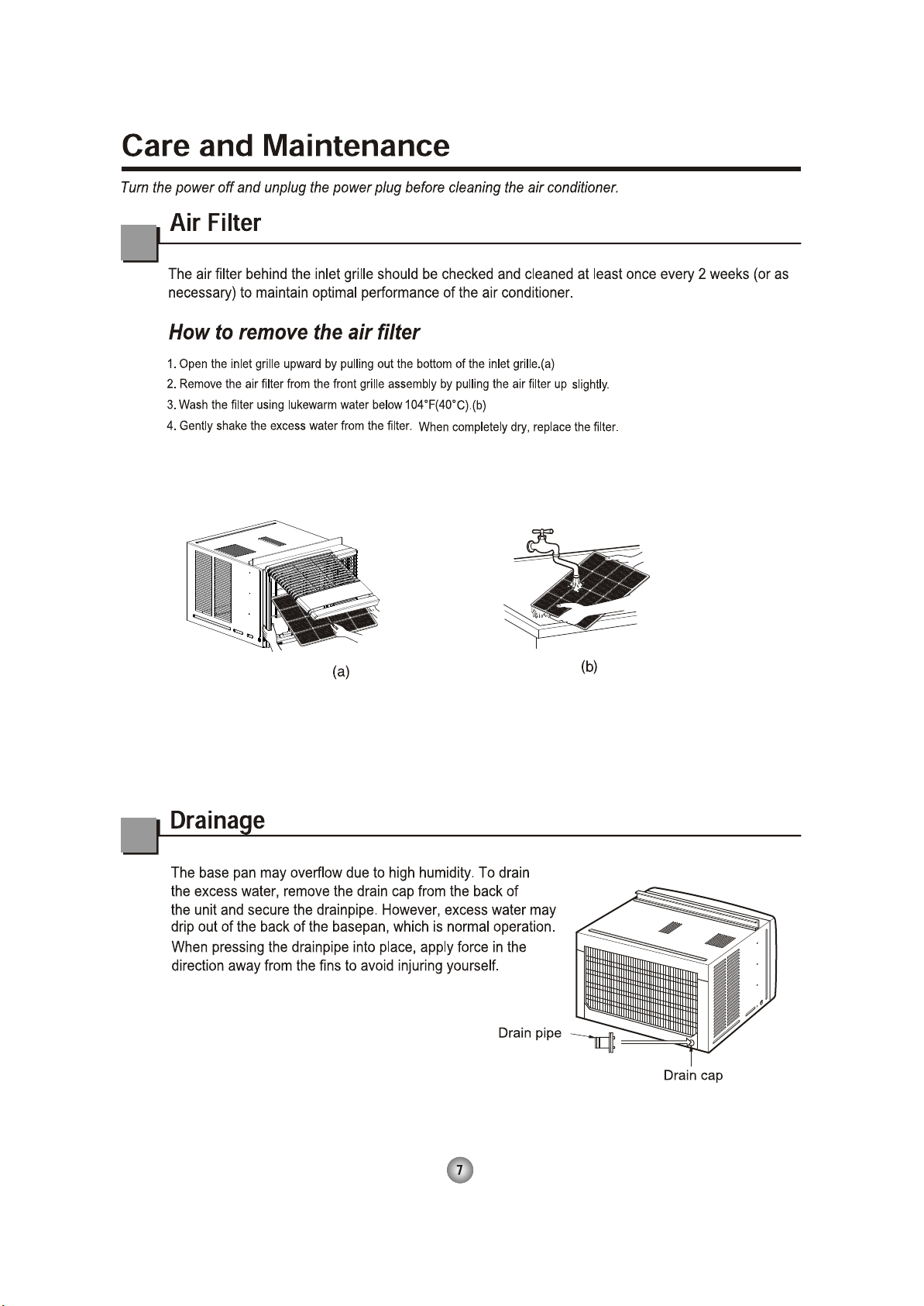
Care and Maintenance .................................................................7
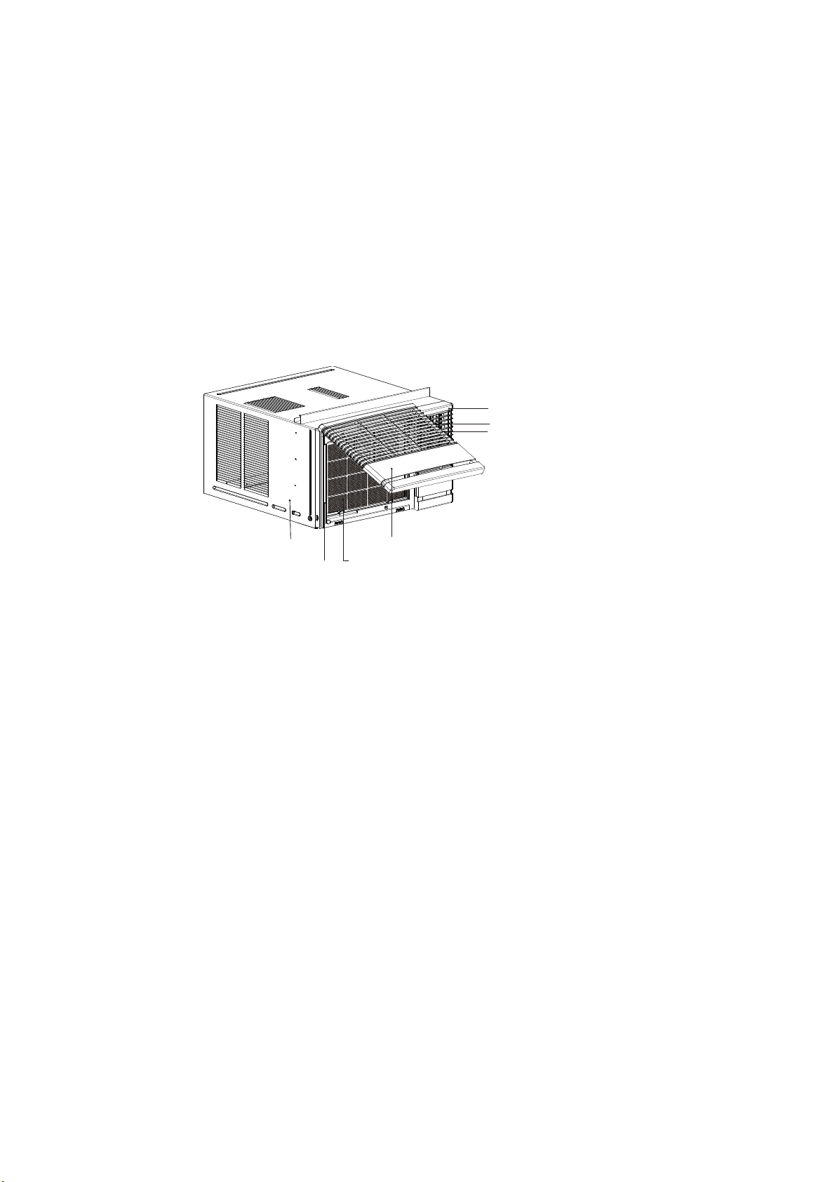
Hardware Location.......................................................................8
Installation Instructions
..........................................................
9
Troubleshooting Tips .................................................................17
Warranty ......................................................................................18
2
Introduction
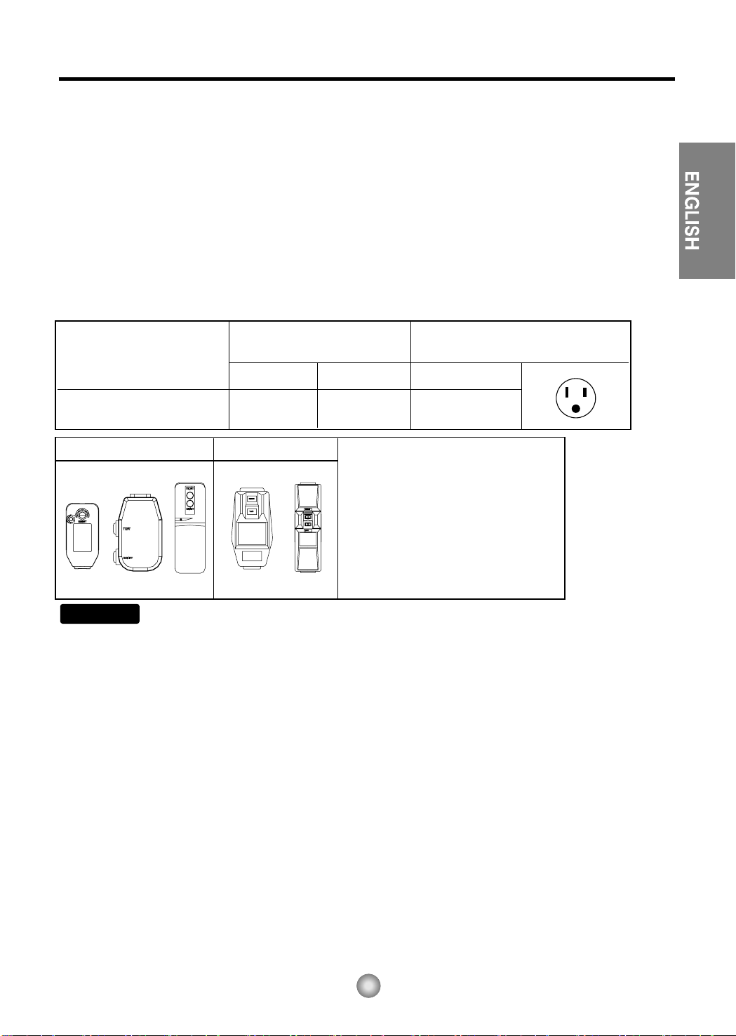
115V~ 230V~
Power cord may include a current
interrupter device. A test and reset button is
provided on the plug case. The device
should be tested on a periodic basis by first
pressing the TEST button and then the
RESET button. If the TEST button does not
trip or if the RESET button will not stay
engaged, discontinue use of the air
conditioner and contact a qualified service
technician.
Before Operating Your Unit
Make sure the wiring is adequate foryour unit.
If you have fuses, they should be of the time delay type. Before you install or relocate this unit, be sure that
the amperage rating of the circuit breaker or time delay fuse does not exceed the amp rating listed in figure 1.
DO NOT use an extension cord.
The cord provided will carry the proper amount of electrical power to the unit; an extension cord will not.
Make sure that the receptacle is compatible with the wall plug provided.
This insures proper grounding. If you have a two-prong receptacle you will need to have the circuit replaced
by a certified electrician with a grounded circuit that meets all national and local codes and ordinances. You
must use the three-prong plug furnished with the air conditioner.
G N E
MODEL
CIRCUIT
TIME DELAY
RATING OR
FUSE
AMP VOLT
PLUG FACE
NEMA NO.
CP06 CP08
15
N OT E !
Aluminum house wiring may pose special problems. Consult a qualified electrician.
125
5-15P
Figure 1
For the Best Cooling Performance and Energy Efficiency
Keep the filter clean
Make sure that your air conditioner is always in top performing condition by cleaning the filter regularly.
Instructions for removing and cleaning the filter can be found on page 7.
Provide good air flow
Make sure that the airflow to and from the unit is clear. Your air conditioner puts the air out at the side of
the unit, and takes in air at the left. Airflow is critical for good operation. It is just as important on the
outside of the building that the airflow around the unit exterior is not blocked.
Unit Placement
If your air conditioner can be placed in a window or a wall that is shaded by a tree or another building, the
unit will operate even more efficiently. Using drapes or blinds on the sunny side of the dwelling will also
add to your unit's efficiency.
Insulation
Good insulation will be a big help in maintaining desirable comfort levels. Doors should have weather
stripping. Be sure to caulk around doors and windows.
For inner cleaning, contact an Authorized Service Center or a dealer.
Do not use harsh detergent that causes corrosion or damage on the unit.
Harsh detergent may also cause failure of product, fire, or electronic shock.
24
24
e

9
ENGLISH
NOTE TO INSTALLER: Leave these
instructions with the air conditioner after
installation is complete.
NOTE TO CONSUMER: Keep this Installation
and Operation Manual for future use.
Important notes:
It is recommended that proper attire be worn
during installation.
For personal safety, this air conditioner must
be properly grounded.
It is important to have the wall outlet and circuit
checked by a qualified electrician if there is any
doubt as to whether a proper ground exists.
CAUTION:
Do not under any circumstances, cut or remove
the third (ground) prong from the power cord.
Do not change the plug on the power cord of
this air conditioner.
Aluminum house wiring may present special
problems ; consult a qualified electrician.
Before You Begin
Read these instructions completely and carefully.
Installation Instructions
❒ Phillips-head screwdriver
❒ Flat-blade screwdriver
❒ Ruler or tape measure
❒ Scissors or knife
❒ Pencil
❒ Level
❒ Hammer
Tools You Will Need
10
How to Install the Unit
HSILGNE
1. To prevent vibration and excess noise,
make sure the unit is installed securely
and firmly.
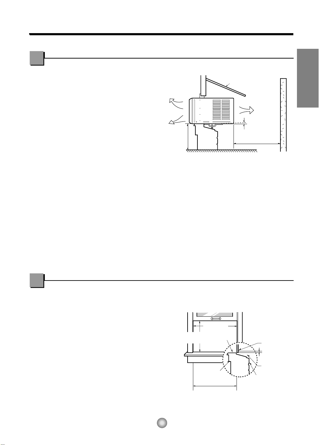
2. If possible Install the unit where the sunlight
does not shine directly on the unit.
Cooled air
Awning
Heat
radiation
3. The outside of the cabinet must extend
outward for at least 12" and there should
be no obstacles, such as a fence or wall,
within 20" from the back of the cabinet, as
it will prevent heat radiation of the
"06~"03
About
Over 20"
condenser.
Restriction of outside air will greatly reduce
the cooling efficiency of the air conditioner.
CAUTION: DO NOT cover or block any of the side louvers.
All side louvers of the cabinet must remain
exposed and unobstructed to the outside of the structure.
4. Install the unit with a rear, downward slope, so the back is slightly lower than the front
(about 1/4" bubble on a level). This will force condensation to flow to the outside.
5. Install the unit with the bottom about 30"- 60" above the floor level.
Fence
1
/2"
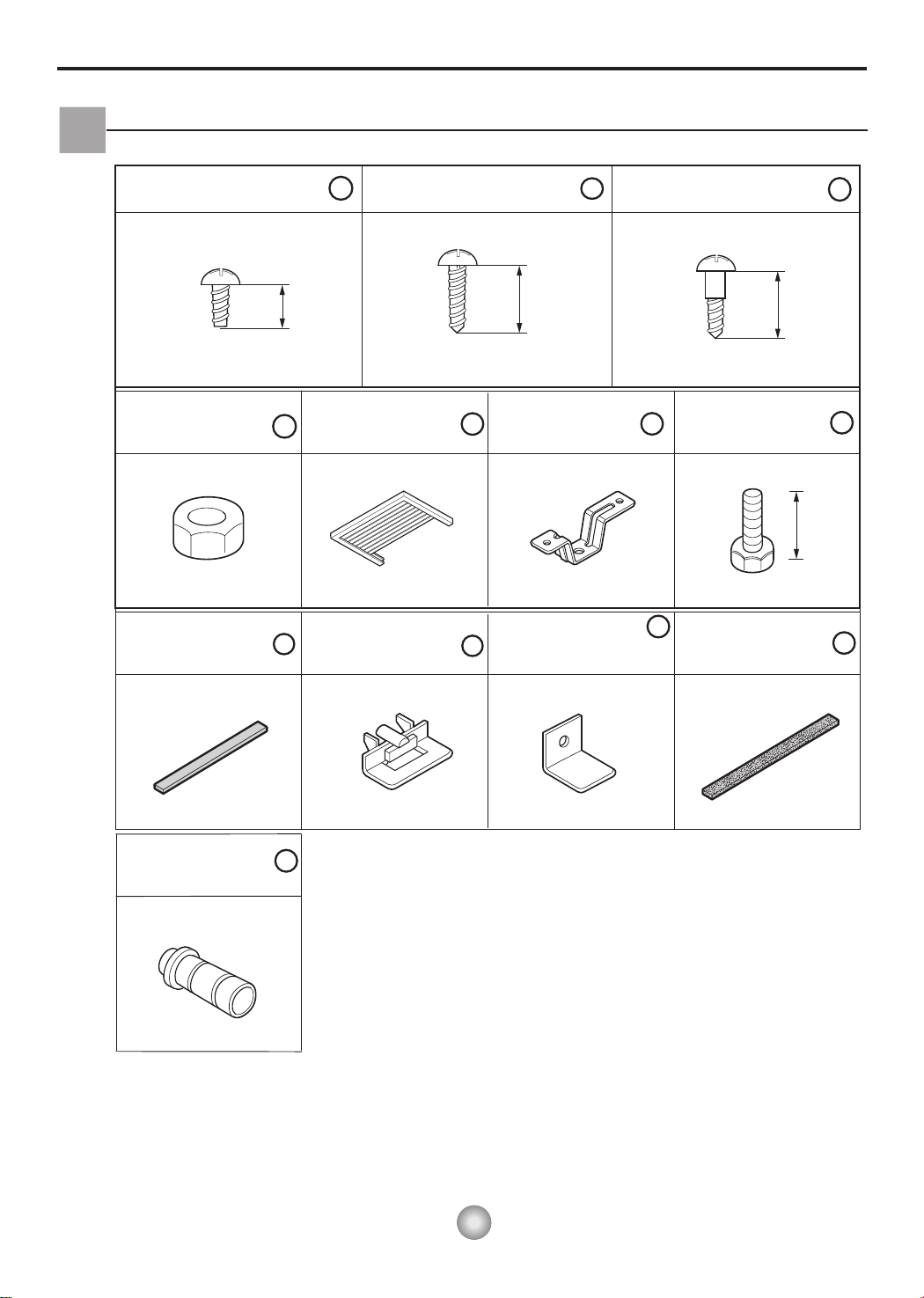
Window Requirements
NOTE: All supporting parts should be secured to sturdy wood, masonry, or metal.
• This unit is designed for installation in standard
double hung windows with actual opening widths
from 22" to 36".
• The top and bottom window sash must open
sufficiently to allow a clear vertical opening of 15"
from the bottom of the upper sash to the window
stool.
(With frame curtain)
22" to 36"
15" min
Interior wall
20
(Without frame curtain)
1
/12" min.
Stool
Offset
1
/2" to 11/4"
Sill
Exte
rior
Installation Kit Contents
Type A:13EA
(SCREW)
Type D:2EA
(NUT)
Type H:1EA
(FOAM-STRIP)
10mm
4
8
1
Type E:2EA
(FRAME CURTAIN)
Type K:2EA
(FRAME-GUIDE)
Type B:3EA
(SCREW)
16mm
5
9
Type F:2EA
(SILL SUPPORT)
Type L:1EA
(WINDOWLOCKINGBRACKET)
2
Type C:5EA
(SCREW)
3
16mm
6
10
Type G:2EA
(BOLT)
Type M:1EA
(FOAM-PE)
7
10mm
11
Type N:1EA
(DRAIN JOINT PIPE)
12
Have the following tools available for installation:
* Screwdriver (Slotted and Phillips) * Ruler
* Knife * Hammer
* Pencil * Level
11
HSILGNE
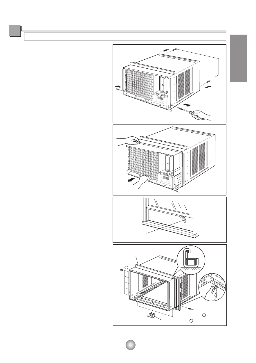
PREPARATION OF CHASSIS
1. Remove the screws which fasten the cabinet
at both sides and at the back.
2. Slide the unit out from the cabinet by gripping
the base pan handle and pulling forward while
bracing the cabinet.
3. Cut the window sash seal to the proper length.
Peel off the backing and attach the Foam-PE to
the underside of the window sash.
4.
5.
6.
Insert the Frame guides into the bottom of the
cabinet.
Insert the Frame Curtain into the
and Frame Guides.
Fasten the curtains to the unit with 8 Type
A screws.
Fig. 1
Fig. 2
Fig. 3
Fig. 4
Suggested Tool Requirements
SCREWDRIVER(+, -), RULER, KNIFE, HAMMER, PENCIL, LEVEL
(Fig .1)
(Fig .2)
(Fig .4)
(Fig .4)
(Fig .3)
Upper Guide
Shipping screws
F
an
0
S
F
p
e
e
d
hr
Mo
ney
Sa
ve
F
a
r
n
®
C
On
o
o
l
l
T
y
imer
A
u
0n
t
o
/0
S
ff
Dr
win
y
g
T
e
mp
Mo
d
e
Power
F
a
0
n
S
F
p
e
e
d
hr
oney
Save
Fan
r
®
C
On
oo
lM
T
l
y
i
mer
A
u
0n/0
t
o
S
f
D
w
f
r
ing
y
T
emp
Mod
e
Power
(Fig .4)
Foam-PE
Upper guide
Screw
(Type A)
1
12
Frame guide
Screw(Type A)
1
9
13
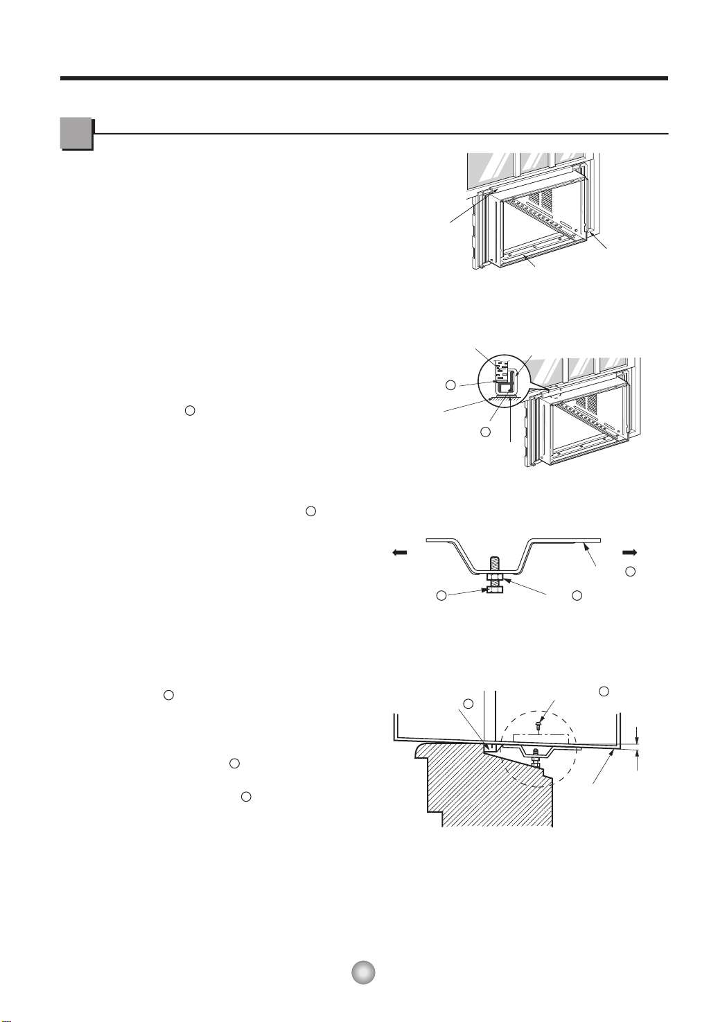
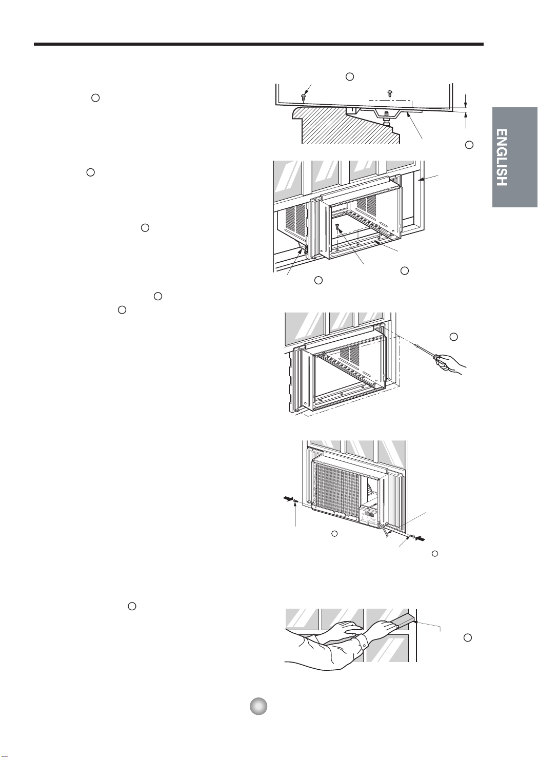
Cabinet Installation
1. Open the window. Mark a line on center of the
window stool.
window stool and align the center mark on the
bottom front with the center line marked in the
window stool. (Fig. 1)
2. Pull the bottom window sash down behind the
Upper Guide until they meet.
Carefully place the cabinet on the
Upper Guide
(Fig. 2)
Window stool
Front Angle
Fig. 1
Window Sash Upper guide
NOTE: Do not pull the window sash down so
tightly that the movement of Frame
Curtain is restricted.
3. Loosely assemble the Sill Support using
5
6
the parts . (Fig. 3)
4. Select the position that will place the Sill
Support near the outer most point on sill.
6
(Fig. 4)
NOTE: Be careful when you install the cabinet
(Frame Guides are broken easily).
5. Attach the Sill Support to the cabinet track
9
6
hole in relation to the selected position using
2 -type A screws in each support.
( Fig. 4).
Foam-PE
11
Cabinet
Frame Curtain
7
Frame Guide
5
Foam-PE
9
Sill Support
4
NutBolt
Screw(Type A)
Cabinet
Fig. 2
ROODTUOROODNI
6
Fig. 3
1
/2"
1
About
ROODTUOROODNI
Fig. 4
14
Fig. 8
6. The cabinet should be installed with a very slight
tilt (about 1/2") downward toward the outside
(See Fig. 5).
Sill Support for balancing the cabinet.
Adjust the bolt and the nut of
6
7. Attach the cabinet to the window stool by driving
the screws [Type B: Length 16mm (5/8 inch)
2
and below.] through the front angle into window
stool.
(Fig. 5)
Screw(Type B)
2
"
2
/
1
About
Sill Support
Sash track
6
8. Pull each Frame Curtain to each window
sash track, and repeat step 2.
9. Attach each Frame Curtain to the window
sash using screws (Type C). ( Fig. 6)
5
(Fig. 5)
5
3
CAUTION: Do not drill a hole in the bottom pan.
The unit is designed to operate with
approximately 1/2" of water in bottom
of pan.
There is no need to add water if the
pan is dry.
10. Slide the unit into the cabinet. ( Fig. 7)
CAUTION: For security purposes, reinstall the 2
screws (Type A) at cabinet's side, that
were removed in step 1 on page 12.
Sill Support
6
Screw(Type A)
Screw(Type B)
F
a
0
n
Sp
F
e
e
d
hr
M
on
e
y
Save
F
a
r
n
®
C
O
o
o
n
l
ly
T
i
m
e
Auto
r
0
n/0
Sw
ff
D
r
y
T
e
m
p
M
od
e
P
o
1
i
ng
w
e
r
Front Angle
2
Type C
Power cord
Fig. 5
3
Fig. 6
11. Cut the Foam-Strip to the proper length
8
(window width) and wedge between the upper
window sash and the lower window sash.
( Fig. 8)
Screw(Type A)
Foam-Strip
1
Fig. 7
8
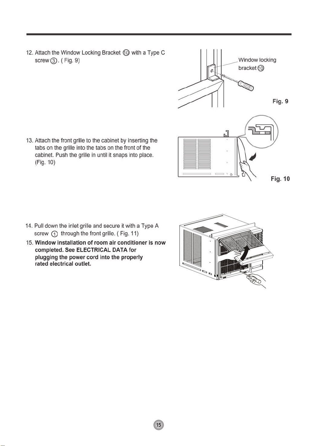
Fig.11
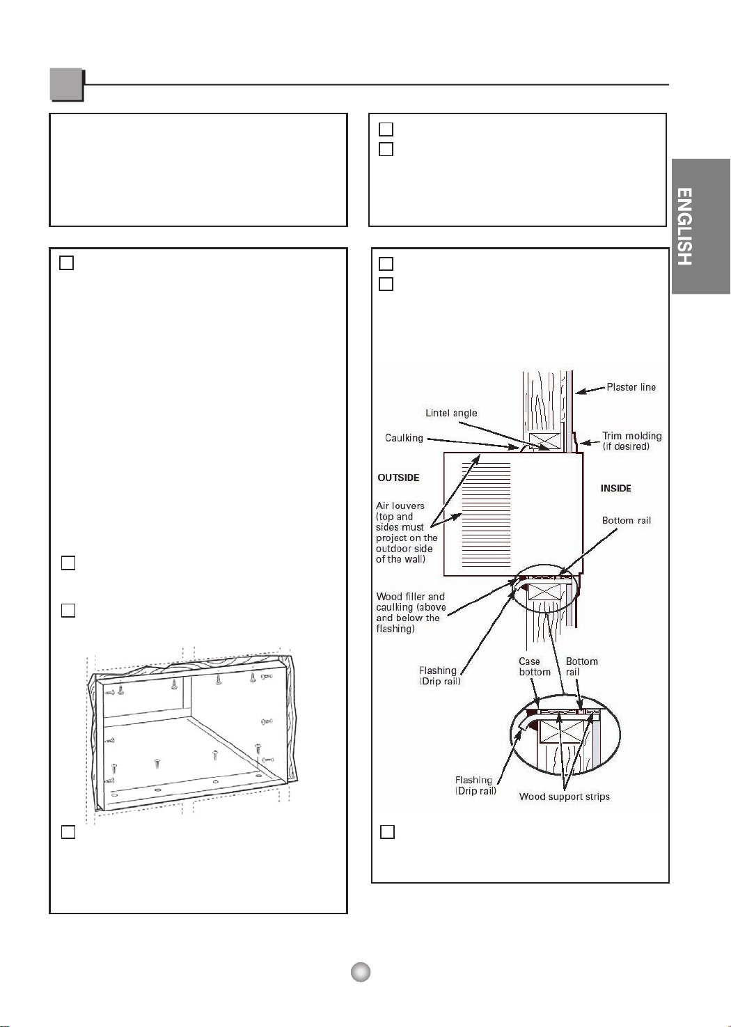
IMPORTANT
IMPORTANT
NOTE:
(cont.)
FINISH THE WALL OPENING
The case may be
in both existing and new construction.
Read completely, then follow step-by-step.
Secure with 14 wood screws anchored at
Ieast an inch into the wall support structure.
Drill pilot holes, if necessary, for
proper installation. If the frame is oversized,
use shims to prevent case distortion.
Caulk all four sides on the outdoor side of
the case to prevent moisture from getting
through to the interior wall. Use of flashing
(drip rail) will further prevent water from
dripping inside the wall and down the
outsida of the building.
NOTE: Obtain all materials locally for
mounting the air conditioner through
the wall.
Through-the-wall installation is not
appropriate if any of the side or top louvers
in the case will be obstructed by the wall.
All side and top louvers in the case must
project on the outdoor side of the wall.
The room side of the case must project
into the room far enough to maximize the
balance of the unit.
The case must be installed level from sideto side and with a slight tilt from front to
rear. Use a level; no more than a 1/2 bubble
will be the correct case slant to the outside.
installed through
the wall
-
-
- -
1
1
D
A
2
Lintel angle is required to support bricks or
blocks above opening.
Flashing is required and should extend the
length of the opening to ensure no inside
cavity leakage occurs.
Remove the air conditioner from the case.
For specific instruction, refer to the Window
Installation Instructions.
Make certain that a wall receptacle is
available close to the hole location or make
arrangeme n tsto install a receptacle.
Place the case in the wall opening and
Place the air conditioner into the case.
For specific instruction, refer to the Window
Installation Instructions.
place wood support strips between the case
bottom and the flashing on both sides of the
bottom rail. They should be the same height
as the bottom rail and the same length as
the wall opening.
A
B
C
B
Through-the-Wall Installation Instructions-Optional
16
17
Troubleshooting Tips
Troubleshooting Tips save time and money! Review the chart below first and you may not need to call for service.
oD oT tahWsesuaC elbissoPmelborP
■ The air conditioner is
unplugged.
■ The fuse is blown/circuit
breaker is tripped.
■ Power failure.
■ The current interrupter
device was tripped on
the power cord.
■ Airflow is restricted.
■ The THERMOSTAT may
not be set high enough.
■ The air filter is dirty.
■ The room may have been
hot.
■ Cold air is escaping.
■ Cooling coils have iced up.
■ Ice blocks the air flow and
stops the air conditioner
from cooling the room.
• Make sure the air conditioner plug is pushed
completely into the outlet.
• Check the house fuse/circuit breaker box and
replace the fuse or reset the breaker.
• If power failure occurs, turn the mode control to Off.
When power is restored, wait 3 minutes to restart the
air conditioner to prevent tripping of the compressor
overload.
• Press the RESET button located on the power
cord plug. If the RESET button will not stay eng
aged, discontinue use of the air conditioner and
contact a qualified service technician.
• Make sure there are no curtains, blinds, or furniture
blocking the front of the air conditioner.
• Push temperature setting button to coolest
temperature setting of 60°F.
• Clean the filter at least every 2 weeks.
See the operating instructions section.
• When the air conditioner is first turned on you need
to allow time for the room to cool down.
• Check for open furnace floor registers and cold air
returns.
• Set the air conditioner's vent to the closed position.
• See Air Conditioner Freezing Up below.
• Set the mode control on high fan until the ice thaws
out. This may indicate a bigger problem.
Air conditioner
does not start
Air conditioner
does not cool as it
should
Air conditioner
freezing up
Normal Operation
• You may hear a pinging noise caused by water being picked up and thrown against the condenser
on rainy days or when the humidity is high. This design feature helps remove moisture and improve
efficiency.
• You may hear the thermostat click when the compressor cycles on and off.
• Water will collect in the base pan during high humidity or on rainy days. The water may overflow and
drip from the outdoor side of the unit.
• The fan may run even when the compressor does not.
• Your air conditioner is designed to cool in warm weather when the outside temperature is above
60°F(16°C) and below 109°F(43°C).
Abnormal Operation
 Loading...