

Page 1
P/NO : MFL67939930
INSTALLATION MANUAL
AIR
CONDITIONER
www.lg.com
Please read this installation manual completely before installing the product.
Installation work must be performed in accordance with the national wiring standards by
authorized personnel only.
Please retain this installation manual for future reference after reading it thoroughly.
Ceilling Concealed Duct
Original instruction (R32)
[Representative] LG Electronics Inc. EU Representative :
LG Electronics European Shared Service Center B.V.
Krijgsman 1, 1186 DM Amstelveen, The Netherlands
[Manufacturer] LG Electronics Inc. Changwon 2nd factory 84, Wanam-ro,
Seongsan-gu, Changwon-si, Gyeongsangnam-do, KOREA
Copyright © 2017 - 2018 LG Electronics Inc. All Rights Reserved.
ENGLISH ITALIANO ESPAÑOL FRANÇAIS DEUTSCH
ΕΛΛΗΝΙΚΆ
ČEŠTINA
NEDERLANDS
POLSKI
LIMBA ROMÂNĂ
Page 2
ENGLISH
2
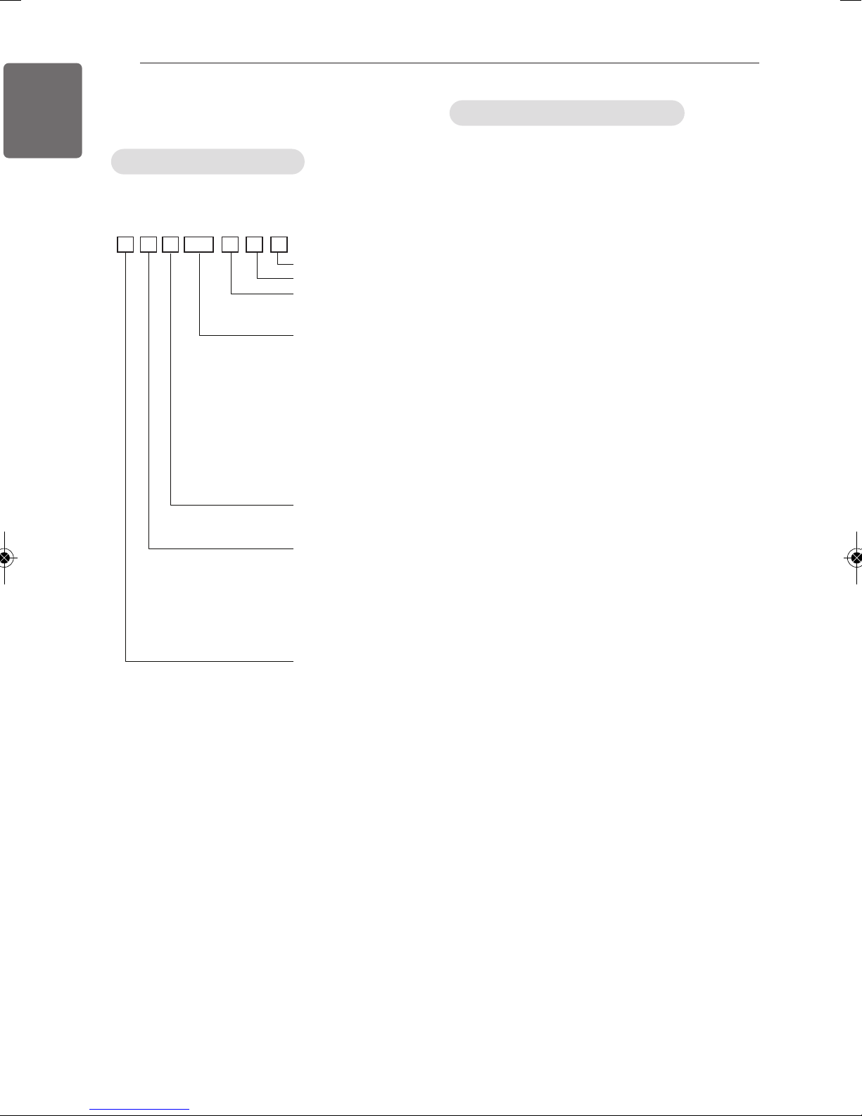
MODEL DESIGNATION
MODEL DESIGNATION
Product information
- Product Name : Air conditioner
- Model Name :
SQSM N B 015
Serial number
Chassis name
Indoor Unit / Outdoor Units
N : Indoor Unit
U : Outdoor Unit
Detailed product type only
for M- series models
AQ : Wall mounted Libero-R
SQ : Wall mounted Libero-E
AH* : ARTCOOL
AW* : ART COOL Mirror
AH : Ceiling Cassette
AHL : Ceiling Concealed Duct
(Low Static)
Detailed product type for
U- / C- series models
L : Low Static
H : High COP
C : Econo
R : Refrigerant R32
Nominal Capacity
Ex) 7,000 Btu/h Class → '07',
18,000 Btu/h Class → '18'
Product type
S : Wall mounted /
ARTCOOL mirror
J : Wall mounted
A : ARTCOOL
T : Ceiling Cassette
B, M : Ceiling Concealed Duct
V : Ceiling Suspended & floor
Q : Console
P : Floor Standing
Connectable Outdoor unit type
M : Indoor units only for
Multi systems
U : Indoor units only for
Single A systems
C : Common Indoor Unit for
Multi and Single CAC
Airborne Noise Emission
The A-weighted sound pressure emitted by
this product is below 70 dB.
** The noise level can vary depending on the
site.
The figures quoted are emission level and are
not necessarily safe working levels.
Whilst there is a correlation between the
emission and exposure levels, this cannot be
used reliably to determine whether or not
further precautions are required.
Factor that influence the actual level of
exposure of the workforce include the
characteristics of the work room and the other
sources of noise, i.e. the number of
equipment and other adjacent processes and
the length of time for which an operator
exposed to the noise. Also, the permissible
exposure level can vary from country to
country.
This information, however, will enable the
user of the equipment to make a better
evaluation of the hazard and risk.
- Additional Information : serial number is
refer to the barcode on the product.
- Max allowable pressure High side :
4.2 MPa / Low side : 2.4 MPa
- Refrigerant : R32
Page 3
TIPS FOR SAVING ENERGY
TIPS FOR SAVING ENERGY
Here are some tips that will help you minimize the power consumption when you use the air
conditioner. You can use your air conditioner more efficiently by referring to the instructions
below:
• Do not cool excessively indoors. This may be harmful for your health and may consume more
electricity.
• Block sunlight with blinds or curtains while you are operating the air conditioner.
• Keep doors or windows closed tightly while you are operating the air conditioner.
• Adjust the direction of the air flow vertically or horizontally to circulate indoor air.
• Speed up the fan to cool or warm indoor air quickly, in a short period of time.
• Open windows regularly for ventilation as the indoor air quality may deteriorate if the air conditioner is used for many hours.
• Clean the air filter once every 2 weeks. Dust and impurities collected in the air filter may block the
air flow or weaken the cooling / dehumidifying functions.
3
ENGLISH
For your records
Staple your receipt to this page in case you need it to prove the date of purchase or for warranty
purposes. Write the model number and the serial number here:
Model number :
Serial number :
You can find them on a label on the side of each unit.
Dealer’s name :
Date of purchase :
Page 4
ENGLISH
4
IMPORTANT SAFETY INSTRUCTIONS
IMPORTANT SAFETY INSTRUCTIONS
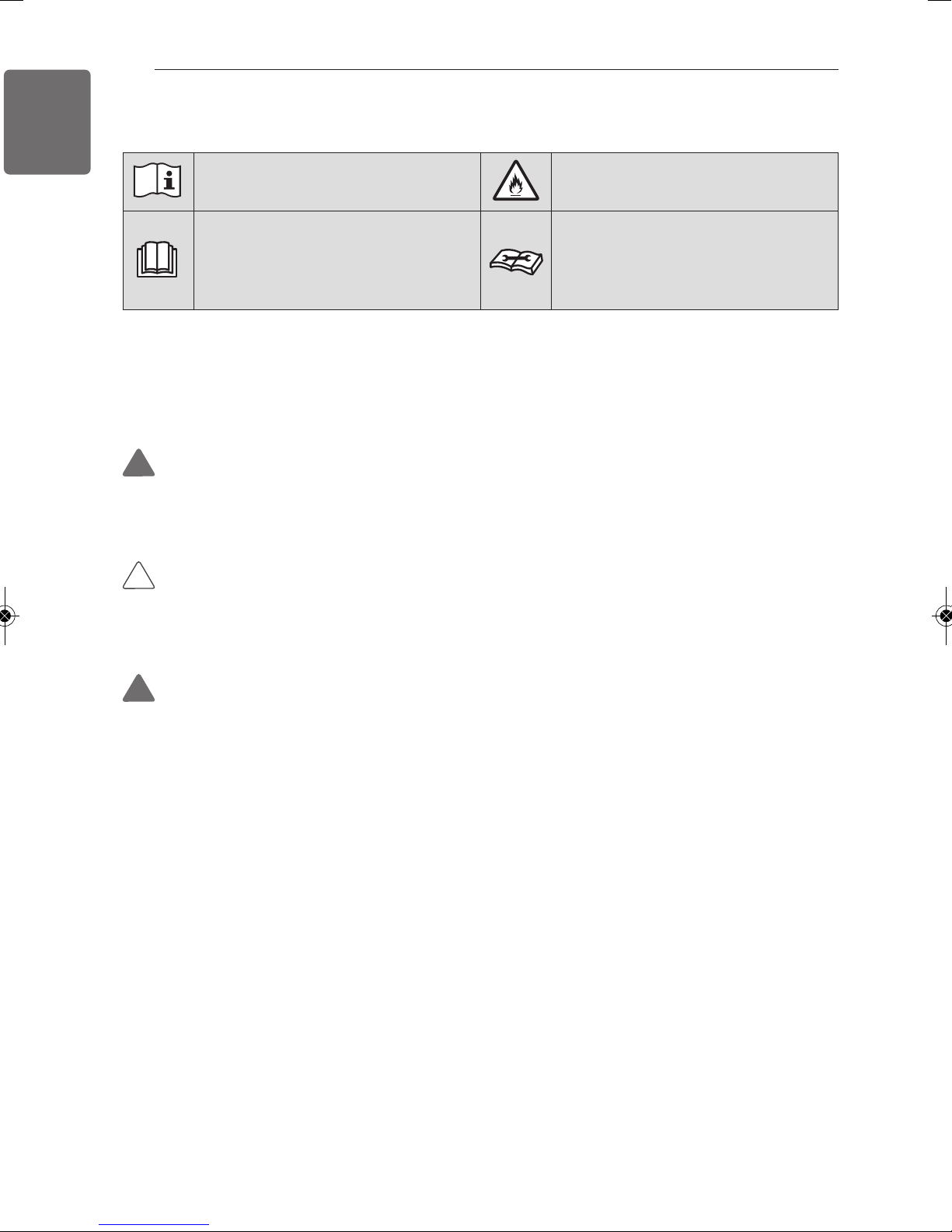
Read the precautions in this manual
carefully before operating the unit.
This symbol indicates that the
Operation Manual should be read
carefully.
This appliance is filled with
flammable refrigerant (R32)
This symbol indicates that a service
personnel should be handling this
equipment with reference to the
Installation Manual.
READ ALL INSTRUCTIONS BEFORE USING THE APPLIANCE.
Always comply with the following precautions to avoid
dangerous situations and ensure peak performance of your
product.
WARNING
!
It can result in serious injury or death when the directions are
ignored.
CAUTION
!
It can result in minor injury or product damage when the
directions are ignored.
WARNING
!
• Installation or repairs made by unqualified persons can result in
hazards to you and others.
• Installation MUST conform with local building codes or, in the
absence of local codes, with the Nation Electrical Code NFPA
70/ANSI C1-1003 or current edition and Canadian Electrical
Code Part1 CSA C.22.1.
• The information contained in the manual is intended for use by
a qualified service technician familiar with safety procedures
and equipped with the proper tools and test instruments.
• Failure to carefully read and follow all instructions in this
manual can result in equipment malfunction, property damage,
personal injury and/or death.
• Compliance with national gas regulations shall be observed.
• Ducts connected to an appliance shall not contain an ignition
source.
Page 5

IMPORTANT SAFETY INSTRUCTIONS
5
Installation
• Always perform grounding. - Otherwise, it may cause electrical
shock.
• Don’t use a power cord, a plug or a loose socket which is
damaged. - Otherwise, it may cause a fire or electrical shock.
• For installation of the product, always contact the service center or
a professional installation agency. - Otherwise, it may cause a fire,
electrical shock, explosion or injury.
• Securely attach the electrical part cover to the indoor unit and the
service panel to the outdoor unit.
- If the electrical part cover of the indoor unit and the service panel
of the outdoor unit are not attached securely, it could result in a
fire or electric shock due to dust, water, etc.
• Always install an air leakage breaker and a dedicated switching
board. - No installation may cause a fire and electrical shock.
ENGLISH
• Do not keep or use flammable gases or combustibles near the air
conditioner. - Otherwise, it may cause a fire or the failure of
product.
• Ensure that an installation frame of the outdoor unit is not
damaged due to use for a long time.
- It may cause injury or an accident.
• Do not disassemble or repair the product randomly. - It will cause a
fire or electrical shock.
• Do not install the product at a place that there is concern of falling
down. - Otherwise, it may result in personal injury.
• Use caution when unpacking and installing. - Sharp edges may
cause injury.
• The appliance shall be stored in a room without continuously
operating ignition sources
(for example: open flames, an operating gas appliance or an
operating electric heater.)
• Two or more people must lift and transport the product. Avoid
personal injury.
• Do not use means to accelerate the defrosting process or to clean,
other than those recommended by the manufacturer.
• Do not pierce or burn refrigerant cycle part.
• Be aware that refrigerants may not contain an odour.
Page 6

ENGLISH
6
• Keep any required ventilation openings clear of obstruction.
• The appliance shall be stored in a well-ventilated area where the
room size corresponds to the room area as specified for operation.
• Refrigerant tubing shall be protected or enclosed to avoid damage.
• Flexible refrigerant connectors (such as connecting lines between
the indoor and outdoor unit) that may be displaced during normal
operations shall be protected against mechanical damage.
• A brazed, welded, or mechanical connection shall be made before
opening the valves to permit refrigerant to flow between the
refrigerating system parts.
• Mechanical connections shall be accessible for maintenance
purposes.
• The appliance shall be disconnected from its power source during
service and when replacing parts.
IMPORTANT SAFETY INSTRUCTIONS
Operation
• Do not share the outlet with other appliances. - It will cause an
electric shock or a fire due to heat generation.
• Do not use the damaged power cord. - Otherwise, it may cause a
fire or electrical shock.
• Do not modify or extend the power cord randomly.
- Otherwise, it may cause a fire or electrical shock.
• Take care so that the power cord may not be pulled during
operation. - Otherwise, it may cause a fire or electrical shock.
• Unplug the unit if strange sounds, smell, or smoke comes from it. Otherwise, it may cause electrical shock or a fire.
• Keep the flames away. - Otherwise, it may cause a fire.
• Take the power plug out if necessary, holding the head of the plug
and do not touch it with wet hands. - Otherwise, it may cause a
fire or electrical shock.
• Do not use the power cord near the heating tools. - Otherwise, it
may cause a fire and electrical shock.
• Do not open the suction inlet of the indoor/outdoor unit during
operation. - Otherwise, it may electrical shock and failure.
• Do not allow water to run into electrical parts. - Otherwise, it may
cause the failure of machine or electrical shock.
• Hold the plug by the head when taking it out. - It may cause
Page 7
IMPORTANT SAFETY INSTRUCTIONS
7
electric shock and damage.
• Never touch the metal parts of the unit when removing the filter. They are sharp and may cause injury.
• Do not step on the indoor/outdoor unit and do not put anything on
it. - It may cause an injury through dropping of the unit or falling
down.
• Do not place a heavy object on the power cord. - Otherwise, it may
cause a fire or electrical shock.
• When the product is submerged into water, always contact the
service center. - Otherwise, it may cause a fire or electrical shock.
• Take care so that children may not step on the outdoor unit.
- Otherwise, children may be seriously injured due to falling down.
• Use a vacuum pump or inert (nitrogen) gas when doing leakage
test or air purge. Do not compress air or oxygen, and do not use
flammable gases. Otherwise, it may cause fire or explosion. There is the risk of death, injury, fire or explosion.
ENGLISH
• Do not turn on the breaker or power under condition that front
panel, cabinet, top cover, control box cover are removed or
opened. - Otherwise, it may cause fire, electric shock, explosion or
death.
• Turn off all devices that cause fire when the refrigerant leaks.,
ventilate the room (example : opening window or using ventilation
unit), and contact with dealer who you purchased the unit.
• The installation of pipe-work shall be kept to a minimum.
• When mechanical connectors are reused indoors, sealing parts
shall be renewed.
• When flared joints are reused indoors, the flare part shall be refabricated.
CAUTION
!
Installation
• Install the drain hose to ensure that drain can be securely done. Otherwise, it may cause water leakage.
• Install the product so that the noise or hot wind from the outdoor
unit may not cause any damage to the neighbors.
- Otherwise, it may cause dispute with the neighbors.
• Always inspect gas leakage after the installation and repair of
Page 8

ENGLISH
8
product. - Otherwise, it may cause the failure of product.
• Keep level parallel in installing the product. - Otherwise, it may
cause vibration or water leakage.
• Any person who is involved with working on or breaking into a
refrigerant circuit should hold a current valid certificate from an
industry-accredited assessment authority, which authorises their
competence to handle refrigerants safely in accordance with an
industry recognised assessment specification.
• Wear adequate personal protection equipment (PPE) when
installing, maintaining or servicing the product.
Operation
• Avoid excessive cooling and perform ventilation sometimes.
- Otherwise, it may do harm to your health.
IMPORTANT SAFETY INSTRUCTIONS
• Use a soft cloth to clean. Do not use wax, thinner, or a strong
detergent. - The appearance of the air conditioner may deteriorate,
change color, or develop surface flaws.
• Do not use an appliance for special purposes such as preserving
animals vegetables, precision machine, or art articles. - Otherwise,
it may damage your properties.
• Do not place obstacles around the flow inlet or outlet.
- Otherwise, it may cause the failure of appliance or an accident.
• The appliance shall be stored so as to prevent mechanical damage
from occurring.
• Servicing shall only be performed as recommended by the
equipment manufacturer. Maintenance and repair requiring the
assistance of other skilled personnel shall be carried out under the
supervision of the person competent in the use of flammable
refrigerants.
• Dismantling the unit, treatment of the refrigerant oil and eventual
parts should be done in accordance with local and national
standards.
• Periodic ( more than once/year ) cleaning of the dust or salt
particles stuck on the heat exchanger by using water.
• Means for disconnection must be incorporated in the fixed wiring
in accordance with the wiring rules.
Page 9
TABLE OF CONTENTS
2 MODEL DESIGNATION
3 TIPS FOR SAVING ENERGY
4 IMPORTANT SAFETY INSTRUCTIONS
10 INSTALLATION PLACES
12 THE INDOOR UNIT INSTALLATION
12 Position of suspension Bolt
15 Wiring Connection
17 Flaring Work
TABLE OF CONTENTS
9
ENGLISH
20 REMOTE CONTROLLER INSTALLATION
22 Wired remote controller installation
23 OPTIONAL OPERATION
23 Installer Setting -Test Run Mode
24 Installer Setting - Setting Address of Central Control
25 Installer Setting -Thermistor
26 Installer Setting -Ceiling Height Selection
27 Installer Setting-Group Setting
28 Installer Setting-Dry Contact Mode Setting
29 Installer Setting-Celsius / Fahrenheit Switching
30 Installer Setting -Optional Function Setting
31 Installer Setting - Remote controller Mode Lock
32 HOW TO SET E.S.P?
32 Installer Setting -E.S.P.
34 Installer Setting - Static Pressure Step Setting
39 SELF-DIAGNOSIS FUNCTION
40 DIP SWITCH SETTING
Page 10
ENGLISH
10
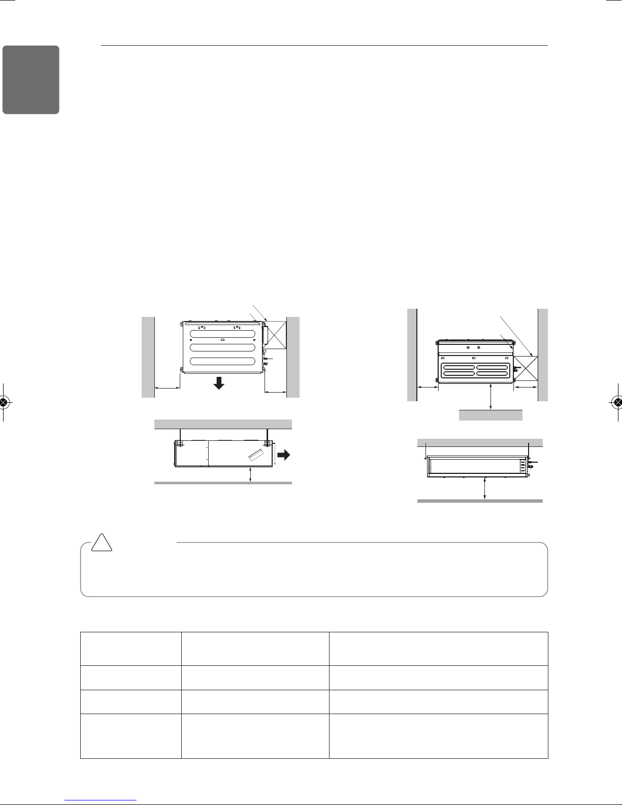
INSTALLATION PLACES
Install the air conditioner in the location that satisfies the following conditions.
- The place shall easily bear a load exceeding four times the indoor unit’s weight.
- The place shall be able to inspect the unit as the figure.
- The place where the unit shall be leveled.
- The place shall allow easy water drainage.
(Suitable dimension “H” is necessary to get a slope to drain as figure.)
- The place shall easily connect with the outdoor unit.
- The place where the unit is not affected by an electrical noise.
- The place where air circulation in the room will be good .
- There should not be any heat source or steam near the unit.
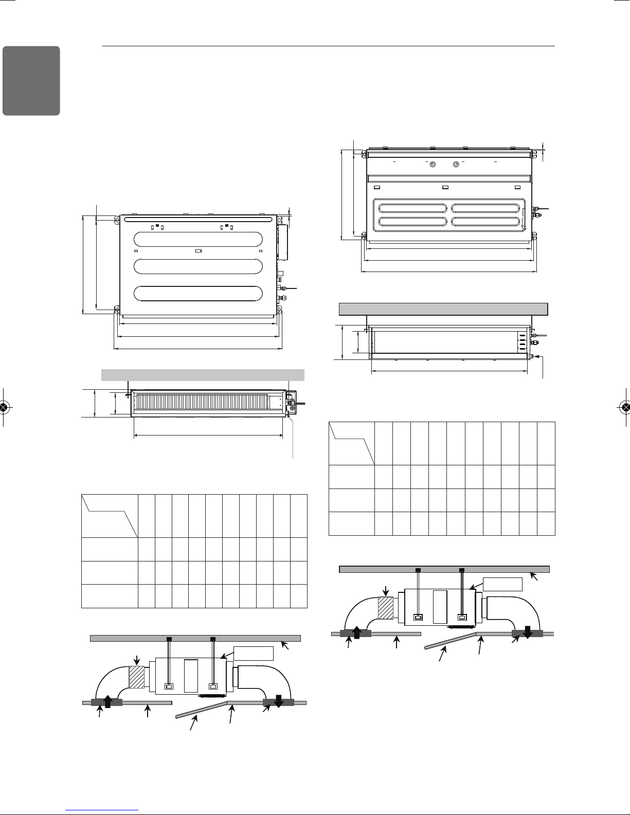
INSTALLATION PLACES
Ceiling Concealed Duct – Low Static Ceiling Concealed Duct – Mid Static
Top view
(unit: mm)
Inspection hole (600 x 600)
Control box
600
Air outlet
600
Top view
(unit: mm)
600
Inspection hole
(600 x 600)
Control box
1000
Front
Side view
(unit: mm)
• Suitable dimension "H" is necessary to get a slope
to drain as shown in the figure
CAUTION
!
Air outlet
H=20 or more
Front view
H
• In case that the unit is installed near the sea, the installation parts may be corroded by salt,
The installation parts (and the unit) should be taken appropriate anti-corrosion measures.
600
[Inspection Hole Standard]
Number of
Inspection hole
1 More than 100cm Sufficient space in the ceiling for servicing.
2 20cm to 100cm Insufficient space. Difficult for servicing
Hole size should be
more than the size
of IDU.
False ceiling & Actual ceiling
Distance between
Remarks
Less than 20cm Minimum height for motor replacement.
Page 11
INSTALLATION PLACES
11
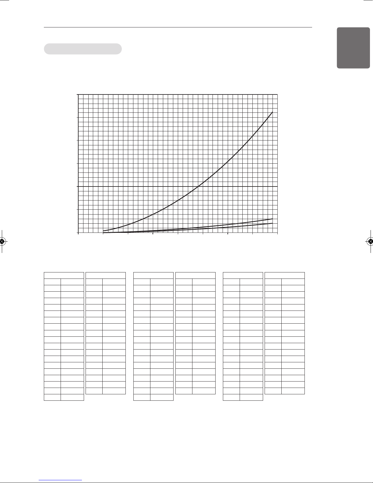
Minimum floor area
- The appliance shall be installed, operated and stored in a room with a floor area larger than the minimum area.
- Use the graph of table to determine the minimum area.
ENGLISH
Amin (m2)
600
500
400
300
200
100
0
0 1.224 2 3 4 5 6 7 8
- m : Total refrigerant amount in the system
- Total refrigerant amount : factory refrigerant charge + additional refrigerant amount
- Amin : minimum area for installation
Floor standing
Wall mounted
Ceiling mounted
m (kg)
Floor location
m (kg) Amin (m
< 1.224
1.224 12.9
1.4 16.82
1.6 21.97
1.8 27.80
2 34.32
2.2 41.53
2.4 49.42
2.6 58.00
2.8 67.27
3 77.22
3.2 87.86
3.4 99.19
3.6 111.20
3.8 123.90
4 137.29
4.2 151.36
4.4 166.12
-
Floor location
2
m (kg) Amin (m
)
4.6 181.56
4.8 197.70
5 214.51
5.2 232.02
5.4 250.21
5.6 269.09
5.8 288.65
6 308.90
6.2 329.84
6.4 351.46
6.6 373.77
6.8 396.76
7 420.45
7.2 444.81
7.4 469.87
7.6 495.61
7.8 522.04
2
)
Wall mounted
m (kg) Amin (m
< 1.224
1.224 1.43
1.4 1.87
1.6 2.44
1.8 3.09
2 3.81
2.2 4.61
2.4 5.49
2.6 6.44
2.8 7.47
3 8.58
3.2 9.76
3.4 11.02
3.6 12.36
3.8 13.77
4 15.25
4.2 16.82
4.4 18.46
-
Wall mounted
2
m (kg) Amin (m
)
4.6 20.17
4.8 21.97
5 23.83
5.2 25.78
5.4 27.80
5.6 29.90
5.8 32.07
6 34.32
6.2 36.65
6.4 39.05
6.6 41.53
6.8 44.08
7 46.72
7.2 49.42
7.4 52.21
7.6 55.07
7.8 58.00
2
)
Ceiling Mounted
m (kg) Amin (m
< 1.224
1.224 0.956
1.4 1.25
1.6 1.63
1.8 2.07
2 2.55
2.2 3.09
2.4 3.68
2.6 4.31
2.8 5.00
3 5.74
3.2 6.54
3.4 7.38
3.6 8.27
3.8 9.22
4 10.21
4.2 11.26
4.4 12.36
-
Ceiling Mounted
2
m (kg) Amin (m
)
4.6 13.50
4.8 14.70
5 15.96
5.2 17.26
5.4 18.61
5.6 20.01
5.8 21.47
6 22.98
6.2 24.53
6.4 26.14
6.6 27.80
6.8 29.51
7 31.27
7.2 33.09
7.4 34.95
7.6 36.86
7.8 38.83
2
)
Page 12
ENGLISH
C
E
G
D
F
I
A
J
B
H
Drainage hole
C
E
G
D
A
J
B
Drainage hole
F
I
H
Inspection Port
Indoor Unit
Ceiling
Canvas Duct
Air Intake Port
Ceiling Board
Ceiling Board
Air Discharge Port
Discharge
Flexible Duct
Intake
Duct
Inspection Port
Indoor Unit
Ceiling
Canvas Duct
Air Intake Port
Ceiling Board
Ceiling Board
Air Discharge Port
Discharge
Flexible Duct
Intake
Duct
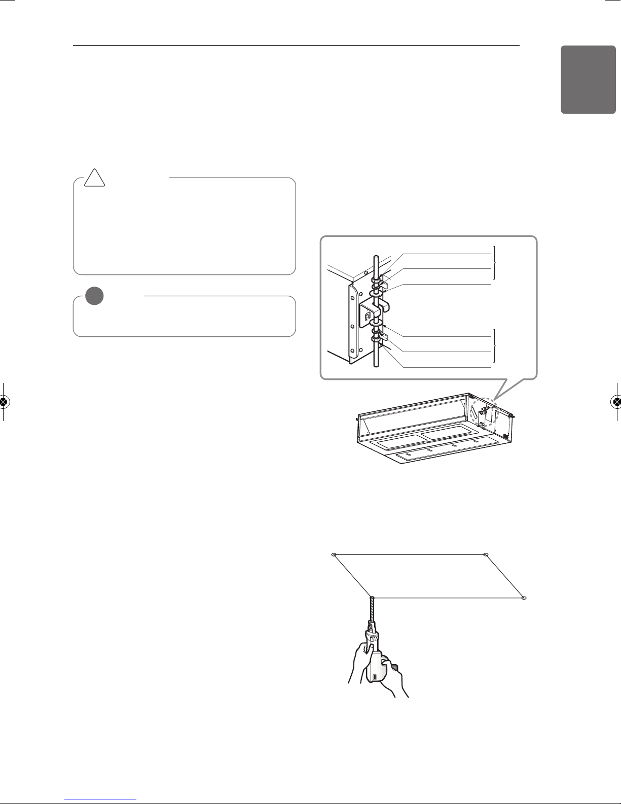
12
THE INDOOR UNIT INSTALLATION
THE INDOOR UNIT INSTALLATION
Position of suspension Bolt
- Apply a joint-canvas between the unit and
duct to absorb unnecessary vibration.
- Apply a filter Accessory at air return hole.
Ceiling Concealed Duct – Low Static
Ceiling Concealed Duct – Mid Static
(Unit: mm)
Dim
ension
Capacity
(kBtu/h
9
12/18
24
A B C D E F G H I J
)
733 772 628 700 36 190 20 660 155 700
933 972 628 700 36 190 20 860 155 900
1133 1172 628 700 36 190 20 1060 155 1100
(Unit: mm)
Dimension
Capacity
(kBtu/h)
18 / 24 / 30
36 / 42
48 / 60
933.4 971.6 619.2
1283.4 1321.6 619.2
1283.4 1321.6 619.2
A B C D E F G H I J
700 30 270 15.2
689.6
30 270 15.2
689.6
30 360 15.2
858 201.4
1208 201.4
1208 291.4
1250
1250
900
Page 13
THE INDOOR UNIT INSTALLATION
13
ENGLISH
- Select and mark the position for fixing bolts
and piping hole.
- Decide the position for fixing bolts slightly
tilted to the drain direction after considering
the direction of drain hose.
- Drill the hole for anchor bolt on the wall.
CAUTION
!
• This air-conditioner uses a drain pump.
• Install the unit horizontally using a level
gauge.
• During the installation, care should be
taken not to damage electric wires.
NOTE
!
Avoid the following installation location.
1 Such places as restaurants and kitchen
where considerable amount of oil steam
and flour is generated. These may cause
heat exchange efficiency reduction, or
water drops, drain pump mal-function. In
these cases, take the following actions;
- Make sure that ventilation fan is enough
to cover all noxious gases from this
place.
- Ensure enough distance from the cooking room to install the air conditioner in
such a place where it may not suck oily
steam.
2 Avoid installng air conditioner in such
places where cooking oil or iron powder is
generated.
3 Avoid places where inflammable gas is
generated.
4 Avoid place where noxious gas is generat-
ed.
5 Avoid places near high frequency genera-
tors.
Install the unit leaning to a drainage hole side
as a figure for easy water drainage.
Position of console Bolt
- A place where the unit will be leveled and
that can support the weight of the unit.
- A place where the unit can withstand its
vibration.
- A place where service can be easily performed.
M10 Nut
M10 SP. washer
M10 washer
M10 washer
M10 SP. washer
M10 Nut
- Select and mark the position for fixing bolts.
- Drill the hole for set anchor on the face of
ceiling.
X 4
X 4
X 4
X 4
X 4
X 4
(Local
supply)
(Local
supply)
Page 14

ENGLISH
1 Set anchor
Old building New building
2 Plate washer
3 Spring washer
4 Nut
5 Suspension
bolts
Drainage hole
CORRECT
5~10mm
Ceiling
Drain Pump use
Ceiling Concealed Duct – Low static
Drainage hole
Drainage hole
INCORRECT
Ceiling Concealed Duct – Mid static
14
THE INDOOR UNIT INSTALLATION
- Insert the set anchor and washer onto the
suspension bolts for locking the suspension
bolts on the ceiling.
- Mount the suspension bolts to the set
anchor firmly.
- Secure the installation plates onto the suspension bolts (adjust level roughly) using
nuts, washers and spring washers.
• Local supply
① Set anchor
② Plate washer - M10
③ Spring washer - M10
④ Nut - W3/8 or M10
⑤ Suspension bolt - W3/8 or M10
CAUTION
!
1. Install declination of the indoor unit is
very important for the drain of the duct
type airconditioner.
2. Minimum thickness of the insulation
for the connecting pipe shall be 10mm.
Front of view
- The unit must be horizontal or declined to
the drain hose connected when finished
installation.
- The unit must be declined to the drain hose
connected when finished installation.
CAUTION
!
• Tighten the nut and bolt top revent unit
falling.
Page 15

700 or less
1 -1.5m
Clamp metal(attached) Drain hose(attached)
Drain raising pipe
300mm or less300mm or less300mm or less
Heat insulation material: Polyethylene
Control box
Control box cover
(On which the Electric
Wiring Connection is put)
1
1
Control terminal board
Remote controler cord
Connection cord between the indoor
unit and the outdoor unit
Ceiling Concealed Duct – Low Static, Mid Static
foam with thickness more than 8 mm.
Drain test
The air conditioner uses a drain pump to drain
water.
Use the following procedure to test the drain
pump operation:
- Connect the main drain pipe to the exterior
and leave it provisionally until the test comes
to an end.
- Feed water to the flexible drain hose and
check the piping for leakage.
- Be sure to check the drain pump for normal
operating and noise when electrical wiring is
complete.
- When the test is complete, connect the flexible drain hose to the drain port on the indoor
unit.
Feed water
Flexible drain hose
(accessory)
Main drain pipe
Drain Pump
Drain
port
Glue the joint
Drain hose connection
Use the clip (accessory)
Drain pan
THE INDOOR UNIT INSTALLATION
HEAT INSULATION
- Use the heat insulation material for the
refrigerant piping which has an excellent
heat-resistance (over 120°C).
- Precautions in high humidity circumstance:
This air conditioner has been tested according to the "KS Standard Conditions with Mist"
and confirmed that there is not any default.
However, if it is operated for a long time in
high humid atmosphere (dew point temperature: more than 23°C), water drops are liable
to fall. In this case, add heat insulation material according to the following procedure:
Fastening band
(accessory)
Indoor
unit
Refrigerant
piping
Thermal insulator
(accessory)
- Heat insulation material to be prepared...
Adiabatic EPDM or NBR with thickness 10 to
20mm.
- Stick glass wool on all air conditioners that
are located in ceiling atmosphere.
Wiring Connection
- Open the control box cover and connect the
Remote controller cord and Indoor power
wires.
- Remove the control box cover for electrical
connection between the indoor and outdoor
unit. (Remove screws ¿)
- Use the cord clamper to fix the cord.
15
ENGLISH
CAUTION
!
The supplied flexible drain hose should not
be curved, neither screwed. The curved or
screwed hose may cause a leakage of
water.
Max 300mm
Metal
clamp
Insulation
Flexible drain hose
Hanger
distance
1~15m
Hanger Bracket
1/50~1/100 slope
Max 700mm
Page 16

ENGLISH
Power wirer
Round pressure terminal
Connect same thickness
wiring to both sides.
It is forbidden to
connect two to one
side.
It is forbidden to
connect wiring of
different thicknesses.
16
THE INDOOR UNIT INSTALLATION
CAUTION
!
The connecting cable connected to the
indoor and outdoor unit should be complied with the following specifications
(This equipment shall be provided with a
cord set complying with the national regulation).
10±3mm
35±5mm
GN/YL
20mm
NORMAL
CROSS-SECTIONAL
AREA 0.75mm
2
Precautions when laying power
wiring
Use round pressure terminals for connections
to the power terminal block.
When none are available, follow the instructions below.
- Do not connect wiring of different thicknesses to the power terminal block. (Slack in the
power wiring may cause abnormal heat.)
- When connecting wiring which is the same
thickness, do as shown in the figure below.
If the supply cord is damaged, it must be
replaced by a special cord or assembly
available from the manufacturer of its
service agent.
The Power cord connected to the unit
should be selected according to the following specifications.
CAUTION
!
- For wiring, use the designated power wire
and connect firmly, then secure to prevent
outside pressure being exerted on the terminal block.
- Use an appropriate screwdriver for tightening
the terinal screws. A screwdriver with a
small head will strip the head and make proper tighterning impossible.
- Over-tightening the terminal screws may
break them.
Page 17

THE INDOOR UNIT INSTALLATION
Pipe
Reamer
Point down
Flare nut
Copper tube
17
ENGLISH
Flaring Work
Main cause for gas leakage is due to defect of
flaring work. Carry out correct flaring work in
the following procedure.
Cut the pipes and the cable
1 Use the piping kit accessory or the pipes
purchased locally.
2 Measure the distance between the indoor
and the outdoor unit.
3 Cut the pipes a little longer than measured
distance.
4 Cut the cable 1.5m longer than the pipe
length.
Copper
pipe
90°
Slanted Uneven Rough
Putting nut on
- Remove flare nuts attached to indoor and
outdoor unit, then put them on pipe/tube
having completed burr removal. (not possible
to put them on after finishing flare work)
Flaring work
1
Firmly hold copper pipe in a bar with the dimension shown in below table table below.
2 Carry out flaring work with the flaring tool.
Pipe diameter
Inch (mm)
Wing nut type Clutch type
A inch (mm)
Burrs removal
1. Completely remove all burrs from the cut
cross section of pipe/tube.
2. While removing burrs put the end of the
copper tube/pipe in a downward direction
while removing burrs location is also
changed in order to avoid dropping burrs
into the tubing.
CAUTION
!
Copper in contact with refrigerants shall
be oxygen-free or de-oxidized, for example Cu-DHP as specified in EN 12735-1
and EN 12735-2
Ø1/4 (Ø6.35)
Ø3/8 (Ø9.52)
Ø1/2 (Ø12.7)
Ø5/8 (Ø15.88)
Bar
Copper pipe
CAUTION
!
• The installation of pipe-work shall be
kept to a minimum
• Flared joint shall be restricted to use
with annealed pipe only, and to pipe
sizes not exceeding a diameter of 20
mm outside diameter.
0.04~0.07
(1.1~1.8)
"A"
0~0.02
(0~0.5)
<Wing nut type>
<Clutch type>
Page 18

ENGLISH
18
THE INDOOR UNIT INSTALLATION
Check
1 Compare the flared work with the figure
by.
2 If a flared section is defective, cut it off
and do flaring work again.
Smooth all round
Inside is shiny without scratches
= Improper flaring =
Even length
all round
Inclined
Surface
damaged
Cracked Uneven
thickness
Connecting the installation pipe
and drain hose to the indoor unit.
1 Align the center of the pipes and suffi-
ciently tighten the flare nut by hand
CAUTION
!
• When mechanical connectors are
reused indoors, sealing parts shall be
renewed.
• When flared joints are reused indoors,
the flare part shall be re-fabricated.
3 When needed to extend the drain hose of
indoor unit, assembly the drain pipe as
shown on the drawing
Drain pipe
Indoor unit drain hose
Adhesive
Vinyl tape(narrow)
Wrap the insulation material
around the connecting portion.
Indoor unit tubing Flare nut Pipes
2 Tighten the flare nut with a wrench
Outside diameter
mm inch kgf.m
Ø6.35 1/4 1.8~2.5
Ø9.52 3/8 3.4~4.2
Ø12.7 1/2 5.5~6.5
Ø15.88 5/8 6.3~8.2
Ø19.05 3/4 9.9~12.1
Open-end wrench
(fixed)
Flare nut
Wrench
Indoor unit tubing
Torque
Connection
pipe
1 Overlap the connection pipe insulation ma-
terial and the indoor unit pipe insulation
material. Bind them together with vinyl
tape so that there may be no gap.
Insulation material
Page 19

2 Set the tubing cutting line upward.
Gas Pipe
Liquid Pipe
Cutting Line
Cutting Line
Good Case Bad Case
* Tubing cutting line have to be upward.
Vinyl tape(narrow)
Connection pipe
Connecting cable
Vinyl tape (wide)
Wrap with vinyl tape
Indoor unit pipe
Pipe
Wrap the area which accommodates the
rear piping housing section with vinyl tape.
THE INDOOR UNIT INSTALLATION
19
ENGLISH
3 Bundle the piping and drain hose together
by wrapping them with vinyl tape sufficient
enough to cover where they fit into the
rear piping housing section.
Wrap with vinyl tape
Pipe
Vinyl tape(wide)
Drain hose
Page 20

ENGLISH
1
2
3
2
3
<Wire guide grooves>
20
REMOTE CONTROLLER INSTALLATION
Please fix tightly using provided screw after placing remote controller setup
board on the place where you like to setup.
- Please set it up not to bend because poor setup could take place if setup board bends.
- Install the product so as not to make a gap with the wall side and to prevent shaking after the
REMOTE CONTROLLER INSTALLATION
Please set up remote controller board fit to the reclamation box if there is a reclamation box.
installation.
Can set up Wired remote controller cable into three directions.
- Setup direction: the surface of wall reclamation, upper, right
- If setting up remote controller cable into upper and right side, please set up after removing
remote controller cable guide groove.
* Remove guide groove with long nose.
① Reclamation to the surface of the wall
② Upper part guide groove
③ Right part guide groove
Page 21

REMOTE CONTROLLER INSTALLATION
Wall
Side
Wall
Side
Wall
Side
Wall
Side
<Connecting order>
<Separating order>
Please check if connector is normally connected.
Connecting cable
Indoor
Unit side
Please fix remote controller upper part
into the setup board attached to the surface of the wall, as the picture below, and
then, connect with setup board by pressing lower part.
- Please connect not to make a gap at the remote
controller and setup board’s upper and lower, right
and left part.
- Before assembly with the installation board, arrange
the Cable not to interfere with circuit parts.
When separating remote controller from
setup board, as the picture below, after
inserting into the lower separating hole
using screw driver and then, spinning
clockwise, remote controller is separated.
21
ENGLISH
- There are two separating holes. Please individually
separate one at a time.
- Please be careful not to damage the inside
components when separating.
Please connect indoor unit and remote controller using connection cable.
Please use extension cable if the distance between wired remote controller
and indoor unit is more than 10m.
CAUTION
!
When installing the wired remote controller, do not bury it in the wall. (It can cause damage in
the temperature sensor.)
Do not install the cable to be 50m or above. (It can cause communication error.)
• When installing the extension cable, check the connecting direction of the connector of the
remote controller side and the product side for correct installation.
• If you install the extension cable in the opposite direction, the connector will not be connected.
• Specification of extension cable: 2547 1007 22# 2 core 3 shield 5 or above.
Page 22

ENGLISH
22
Wired remote controller installation
Since the room temperature sensor is in the remote controller, the remote controller box should
be installed in a place away from direct sunlight, high humidity and direct supply of cold air to
maintain proper space temperature. Install the remote controller about 5ft(1.5m) above the floor
in an area with good air circulation at an average temperature.
Do not install the remote controller where it can be affected by:
- Drafts, or dead spots behind doors and in corners.
- Hot or cold air from ducts.
- Radiant heat from sun or appliances.
- Concealed pipes and chimneys.
- Uncontrolled areas such as an outside wall behind the remote controller.
- This remote controller is equipped with a seven segment LED. display. For proper display of the
remote controller LED's, the remote controller should be installed properly as shown in Fig.1.
(The standard height is 1.2~1.5 m from floor level.)
REMOTE CONTROLLER INSTALLATION
Direct
Sun ray contact area
no
yes
no
no
5feet
(1.5meters)
Page 23

OPTIONAL OPERATION
Installer Setting -Test Run Mode
After installing the product, you must run a Test Run mode.
For details related to this operation, refer to the product manual.
If pressing button long for 3 seconds, it
1
enters into remote controller setter setup
mode.
- If pressing once shortly, it enters into user
setup mode. Please press more than 3
seconds for sure.
- Please cancel the right and left of wind
direction for RAC product.
OPTIONAL OPERATION
23
ENGLISH
Function Code Set
Setup figure '01' blinks at the lower part of
2
indication window.
Press button to start.
3
During the test run, pressing the below
4
button will exit the test run.
- Select operation, temperature up/down,
wind flow control, wind direction,
start/stop button.
Page 24

ENGLISH
24
Installer Setting - Setting Address of Central Control
It's the function to use for connecting central control.
Please refer to central controller manual for the details
OPTIONAL OPERATION
If pressing button long for 3
1
seconds, it enters into remote controller
setter setup mode.
- If pressing once shortly, it enters into
user setup mode. Please press more
than 3 seconds for sure.
If entering into address setup mode by using
2
button, it indicates as picture below.
Group No
Function Code
Indoor No.
Set Group No. by pressing
3
button.(0~F)
Move to Indoor No. setting option
4
by pressing button.
Set Indoor No. by pressing
5
button.
Press button to save.
6
Pressing button will exit settings mode.
7
❈ After setup, it automatically gets out of setup
mode if there is no button input for 25
seconds.
❈ When exiting without pressing set button, the
manipulated value is not reflected.
Page 25

Installer Setting -Thermistor
OPTIONAL OPERATION
If pressing button long for 3
1
seconds, it enters into remote controller
setter setup mode.
- If pressing once shortly, it enters into
user setup mode. Please press more
than 3 seconds for sure.
If moving to room temperature perception sensor
2
selection menu by pressing button, it
indicates as picture below.
25
ENGLISH
Set Thermistor value by pressing
3
button. (01: Remote Controller,
02: Indoor, 03: 2TH)
Function Code Thermistor setting
Press button to save.
4
Pressing button will exit settings mode.
❈ After setup, it automatically gets out of setup
5
mode if there is no button input for 25
seconds.
❈ When exiting without pressing set button, the
manipulated value is not reflected.
<Thermistor Table>
Temperature sensor selection Function
01 Remote controller Operation in remote controller temperature sensor
02 Indoor unit Operation in indoor unit temperature sensor
Cooling
03 2TH
Heating
* The function of 2TH has different operation characteristics according to the product.
Operation of higher temperature by comparing indoor unit's and wired
remote controller’s temperature.
(There are products that operate at a lower temperature.)
Operation of lower temperature by comparing indoor unit's and wired
remote controller's temperature.
Page 26

ENGLISH
26
Installer Setting -Ceiling Height Selection
This function is to adjust FAN Airflow rate according to ceilingheight (only cassette model)
OPTIONAL OPERATION
If pressing button long for 3
1
seconds, it enters into remote controller
setter setup mode.
- If pressing once shortly, it enters into
user setup mode. Please press more
than 3 seconds for sure.
If moving to ceiling height selection menu by
2
pressing button, it indicates as picture below.
Select ceiling height value by pressing
3
button. (01:Low, 02:Standard,
03:High, 04Very high)
Function Code Thermistor setting
Press button to save.
4
Pressing button will exit settings mode.
❈ After setup, it automatically gets out of setup
5
mode if there is no button input for 25
seconds.
❈ When exiting without pressing set button, the
manipulated value is not reflected.
<Ceiling Height Selection Table>
Ceiling Height Level Description
01 Low Decrease the indoor airflow rate 1 step from standard level
02 Standard Set the indoor airflow rate as standard level
03 High Increase indoor airflow rate 1 step from standard level
04 Super high Increase indoor airflow rate 2 steps from standard level
* Ceiling height setting is available only for some products.
* Ceiling height of ‘Super high’ function may not exist depending on the indoor unit.
* Refer to the product manual for more details.
Page 27

OPTIONAL OPERATION
Installer Setting-Group Setting
It is a function for settings in group control, or 2-remote controller control.
If pressing button long for 3 seconds, it
1
enters into remote controller setter setup
mode.
- If pressing once shortly, it enters into
user setup mode. Please press more than
3 seconds for sure.
If pressing button repeatedly, it moves to
2
master/slave selection menu as picture below.
27
ENGLISH
Select Master/ Slave by pressing
3
button.
(00: Slave, 01: Master)
Function Code Master/Slave value
Press button to save.
4
Pressing button will exit settings mode.
5
❈ After setup, it automatically gets out of setup mode
if there is no button input for 25 seconds.
❈ When exiting without pressing set button, the
manipulated value is not reflected.
Remote controller Function
Master
Indoor unit operates based on master remote controller at group control.
(Master is set when delivering from the warehouse.)
Slave
* Refer to the 'group control' part for details
- When controlling in groups, basic operation settings, airflow strength weak/medium/strong,
lock setting of the remote controller, time settings, and other functions may be restricted.
Setup all remote controllers except one master remote controller to slave
at group control
Page 28

ENGLISH
28
Installer Setting-Dry Contact Mode Setting
Dry contact function is the function that is possible to use only when dry contact equipment is
separately purchased/setup.
OPTIONAL OPERATION
If pressing button long for 3
1
seconds, it enters into remote controller
setter setup mode.
- If pressing once shortly, it enters into
user setup mode. Please press more
than 3 seconds for sure.
If pressing button repeatedly, it moves to
2
remote controller dry contact mode setup menu
as picture below.
Select Dry contact setting by
3
pressing button.
(00 : Automatic, 01 : manual)
Function Code Dry Contact
setting value
Press button to save.
4
Pressing button will exit settings mode.
5
❈ After setup, it automatically gets out of setup
mode if there is no button input for 25
seconds.
❈ When exiting without pressing set button, the
manipulated value is not reflected.
What is Dry Contact?
Like hotel card key and body perception sensor, it is the signal of the point of contact when using
air-conditioner by interlocking.
- Please refer to dry contact manual for more details.
Page 29

OPTIONAL OPERATION
Function Code conversion mode value
If pressing button long for 3
seconds, it enters into remote
controller setter setup mode.
- If pressing once shortly, it enters
into user setup mode.
Please press more than 3 seconds for
sure.
1
Press button to exit or system
will automatically exit after 25
seconds without any input.
5
Repeat pressing button to select
Function code 12.
Ex) Fahrengeit Setting
2
Select Temperature unit mode by pressing
button.
(00: Celsius, 01: Fahrenheit)
3
Press button to save or release.
4
Installer Setting-Celsius / Fahrenheit Switching
This function is used for switching the display between Celsius and Fahrenheit.
(Optimized only for U.S.A)
29
ENGLISH
h Whenever press button in Fahrenheit mode, the temperature will increase/drop 2
degrees.
Page 30

ENGLISH
30
Installer Setting -Optional Function Setting
Setting feature for indoor unit when air cleaning / heater / humidifier / Up/down grill / Ventilation
KIT / Auxiliary Heater is newly installed, or installed unit is removed.
OPTIONAL OPERATION
If pressing button long for 3
1
seconds, it enters into remote controller
setter setup mode.
- If pressing once shortly, it enters into
user setup mode. Please press more
than 3 seconds for sure.
If pressing button repeatedly, it moves to the
2
selected option function code as picture below.
Select existing condition of
3
each mode by pressing
button.
(00: not installed,
01 : installed)
Function Code Existing condition
Press button to save.
4
Function
Plasma purification
Electric heater
Dehumidifier
Elevation grill
Ventilation kit
Auxiliary heater
Code
20
21
22
23
24
25
Pressing button will exit settings mode.
5
❈ After setup, it automatically gets out of setup
mode if there is no button input for 25
seconds.
❈ When exiting without pressing set button, the
manipulated value is not reflected.
Page 31

OPTIONAL OPERATION
Installer Setting - Remote controller Mode Lock
This function is used to limit ‘operation-mode’ selection setting.
Press and hold button for
1
more than 3 seconds to enter the
installer settings mode.
Move to the installer code number 42 in the
2
menu using button.
31
ENGLISH
Select the remote control master/slave
3
using button.
Code value for mode
lock setting
code Description
42:00
42:01
42:02
Press button to save the setting.
Doesn’t limit operation mode setting.
User can setting to cooling mode only.
User can setting to heating mode only.
Set value
4
h It can limit only wired remote controller button. other controllers can change operation mode.
(for example wireless remote controller and central controller)
Press button to exit.
5
Page 32

ENGLISH
32
HOW TO SET E.S.P?
Installer Setting -E.S.P.
This is the function that decides the strength of the wind for each wind level and because this
function is to make the installation easier.
- If you set ESP incorrectly, the air conditioner may malfunction.
- This setting must be carried out by a certificated-technician.
HOW TO SET E.S.P?
If pressing button long for 3
1
seconds, it enters into remote controller
setter setup mode.
- If pressing once shortly, it enters into
user setup mode. Please press more
than 3 seconds for sure.
If entering into ESP setup mode by using
2
button, it indicates as the picture below.
Function code,
ESP code
ESP value
ESP step
Function Code ESP value
Select ESP fan step by pressing
3
button. (01: very low, 02: low, 03:
medium, 04: high, 05: power)
Move to ESP value setting by pressing
4
button.
(It is 000 when delivering
from the warehouse.)
Press button to setup ESP value.
5
(It is possible to setup ESP
value from 1 to 255, and 1 is the
smallest and 255 is the biggest.)
- When setting ESP value on the product without very weak wind or power wind function, it may
not work.
Page 33

HOW TO SET E.S.P?
Function code,
ESP code
ESP value
Press button to save.
7
Select ESP fan step again by using
button and setup ESP value, as No. 4 and 5,
that corresponds each wind flow
6
Press button to exit.
❈ After setup, it automatically gets out of
setup mode if there is no button input for
25 seconds.
❈ When exiting without pressing set button,
the manipulated value is not reflected.
8
33
ENGLISH
- Please be careful not to change the ESP value for each fan step.
- It does not work to setup ESP value for very low/power step for some products.
- ESP value is available for specific range belongs to the product.
Page 34

ENGLISH
34
Installer Setting - Static Pressure Step Setting
This function is applied to only duct type. Setting this in other cases will cause malfunction.
This function is only available on some products.
This is the function that static pressure of the product is divided in 11 steps for setting.
HOW TO SET E.S.P?
When pressing the button and
1
button simultaneously for more than 3
seconds, the system will be entered into the
installer setting mode.
- After entering into the installer setting
mode, select the static pressure step
setting code value by pressing the
button.
* Static pressure step setting code value : 32
Select the desired setting value with the
2
temperature up(
ƞ
), down(Ơ) button.
Function Code
00: use static pressure (code 06) set value
01~ 11: static pressure step (code 32) set value
When pressing button, currently
3
established static pressure value will be set
up.
When pressing the button and
4
button simultaneously for more than 3
seconds after the setting has been
completed, the setting mode will be released.
- If there isn’t any button input for more than
25 seconds, the installer setting mode will
also be released.
- Static Pressure (Code 06) setting will not be used if Static Pressure Step (Code 32) setting is
being used.
- For the static pressure value for each step, refer to the next page Table. 1
Existing condition
Page 35

Ceiling Concealed Duct – Low static
Table 1
Model Step CMM
LOW 5.5 69 76 83 91 101 111
CL09R.N20
Model Step CMM
CL12R.N20
MID 7 81 87 94 101 109 117
HIGH 9 97 103 108 117 124 131
LOW 7 78 82 87 93 100 107
MID 8.5 87 91 94 100 108 116
HIGH 10 96 100 103 109 117 125
0(0) 1(10) 2(20) 3(29) 4(39) 5(49)
32:01 32:02 32:03 32:04 32:05 32:06
0(0) 1(10) 2(20) 3(29) 4(39) 5(49)
32:01 32:02 32:03 32:04 32:05 32:06
HOW TO SET E.S.P?
Static Pressure [mmAq (Pa)]
Setting Value
Static Pressure [mmAq (Pa)]
Setting Value
35
ENGLISH
Static Pressure [mmAq (Pa)]
Model Step CMM
LOW 10 96 100 103 109 117 125
CL18R.N20
Model Step CMM
CL24R.N30
NOTE
!
1. The above table shows the correlation between the air rates and E.S.P.
2. Be sure to set the value refering table 1. Unexpected set value will cause mal-function.
3. Table 1 is based at 230V. According to the fluctuation of voltage, air flow rate varies.
MID 12.5 109 113 117 123 130 137
HIGH 15 120 124 129 134 141 147
LOW 12 89 95 102 106 120 130
MID 16 102 108 115 125 131 139
HIGH 20 125 131 136 141 144 147
0(0) 1(10) 2(20) 3(29) 4(39) 5(49)
Setting Value
32:01 32:02 32:03 32:04 32:05 32:06
Static Pressure [mmAq (Pa)]
0(0) 1(10) 2(20) 3(29) 4(39) 5(49)
Setting Value
32:01 32:02 32:03 32:04 32:05 32:06
Page 36

ENGLISH
36
Ceiling Concealed Duct – Mid static
Table 2
HOW TO SET E.S.P?
Model Step CMM
LOW 13 73 74 77 88 93 103 111 117 120 125 128
CM18R.N10
CM24R.N10
Model Step CMM
UM30R.N10
MID 14.5 76 77 85 91 97 107 114 121 125 128 131
HIGH 16.5 85 87 90 94 103 110 118 125 128 131 134
LOW 14.5 76 77 85 89 97 106 114 121 124 127 132
MID 16.5 85 87 90 94 103 111 118 125 128 131 136
HIGH 18 90 92 95 99 108 115 122 129 132 135 138
LOW 18 96 102 107 110 114 118 122 125 127 130 132
MID 20 102 110 114 118 121 125 127 130 133 134 136
HIGH 22 110 117 121 124 127 130 133 136 137 138 140
Static Pressure[mmAq(Pa)]
2(20) 2.5(25) 3(29) 4(39) 6(59) 8(78) 10(98) 12(118) 13(127) 14(137) 15(147)
Setting Value
32:01 32:02 32:03 32:04 32:05 32:06 32:07 32:08 32:09 32:10 32:11
Static Pressure[mmAq(Pa)]
2.5(25) 4(39) 5(49) 6(59) 7(69) 8(78) 9(88) 10(98) 11(108) 13(127) 15(147)
Setting Value
32:01 32:02 32:03 32:04 32:05 32:06 32:07 32:08 32:09 32:10 32:11
Model Step CMM
LOW 24 88 91 95 100 101 108 113 115 118 121 128
UM36R.N20
MID 28 93 97 101 105 108 115 118 120 124 127 134
HIGH 32 101 105 109 112 115 119 123 126 128 133 137
Static Pressure[mmAq(Pa)]
4(39) 5(49) 6(59) 7(69) 8(78) 9(88) 10(98) 11(108) 12(118) 13(127) 15(147)
Setting Value
32:01 32:02 32:03 32:04 32:05 32:06 32:07 32:08 32:09 32:10 32:11
Page 37

Model Step CMM
LOW 28 100 103 106 110 114 118 121 125 128 133 136
UM42R.N20
Model Step CMM
UM48R.N30
MID 33 108 111 114 118 122 125 128 131 134 138 141
HIGH 38 117 120 124 127 130 133 135 138 141 144 147
LOW 28 74 76 79 82 89 92 94 96 99 102 107
MID3478828489949698101104106112
HIGH 40 83 89 92 94 98 100 102 105 108 110 116
HOW TO SET E.S.P?
Static Pressure[mmAq(Pa)]
5(49) 6(59) 7(69) 8(78) 9(88) 10(98) 11(108) 12(118) 13(127) 14(137) 15(147)
Setting Value
32:01 32:02 32:03 32:04 32:05 32:06 32:07 32:08 32:09 32:10 32:11
Static Pressure[mmAq(Pa)]
4(39) 5(49) 6(59) 7(69) 8(78) 9(88) 10(98) 11(108) 12(118) 13(127) 15(147)
Setting Value
32:01 32:02 32:03 32:04 32:05 32:06 32:07 32:08 32:09 32:10 32:11
37
ENGLISH
Model Step CMM
LOW 40 82 89 92 94 98 100 102 105 108 110 113
UM60R.N30
MID 45 90 92 96 98 102 104 106 109 112 114 117
HIGH 50 94 97 100 104 107 109 112 115 117 119 121
Static Pressure[mmAq(Pa)]
4(39) 5(49) 6(59) 7(69) 8(78) 9(88) 10(98) 11(108) 12(118) 13(127) 15(147)
Setting Value
32:01 32:02 32:03 32:04 32:05 32:06 32:07 32:08 32:09 32:10 32:11
Page 38

ENGLISH
38
1. Be sure to set the value refering table 2. Unexpected set value will cause mal-function.
2. Table 2 is based at 230V. According to the fluctuation of voltage, air flow rate varies.
3. Factory Set(External Static Pressure) each Model
HOW TO SET E.S.P?
NOTE
!
Model Factory set (E.S.P.) mmAq(Pa)
CM18R.N10
CM24R.N10
UM30R.N10
UM36R.N20
UM42R.N20
UM48R.N30
UM60R.N30
* If it is zero static pressure, please set value below Maximum value.
Model Maximum value
CM18R.N10
CM24R.N10
UM30R.N10
UM42R.N20
UM48R.N30
UM60R.N30
6(59)
115
120UM36R.N20
98
Page 39

SELF-DIAGNOSIS FUNCTION
Indoor Unit Error
Ex) Error 03 (Remote controller error)
3 Times 3 Times 3 Times
LED02G
(GREEN)
2 s
2 s
SELF-DIAGNOSIS FUNCTION
39
ENGLISH
CL09R N20
CL12R N20
Error
Code
CL18R N20
CM18R N10
Description
CM24R N10
UM30R N10
CL24R N30
01 Indoor Room sensor error 0
02 Indoor in-pipe sensor error 0
03 Remote controller error 0
04 Drain pump error 0
05 Communication error indoor and outdoor 0
06 Indoor out-pipe sensor error 0
09 EEPROM error (indoor) 0
10 BLDC motor fan lock (indoor)
1time ◑
LED 1
(Red)
1time ◑
2times ◑
3times ◑
4times ◑
5times ◑
6times ◑
9times ◑
UM36R N20
UM42R N20
UM48R N30
UM60R N30
LED 2
(Green)
0 OFF
Indoor
status
OFF
OFF
OFF
OFF
OFF
OFF
OFF
* Because remote controller turn off when occur ERROR in simultaneous operation system, it
should check LED blinks of outdoor in order to confirm error code.
* Repeatedly after LED1 is turned on and off as the Error code number of tens digit, LED2 is
turned on and off as the Error code number of single-digit.
Page 40

ENGLISH
Indoor PCB
40
DIP SWITCH SETTING
SW3 Group Control
SW4
SW5 Installation
DIP SWITCH SETTING
Indoor PCB
Indoor PCB
Function Description Setting Off Setting On Default
Dry Contact
Mode
Selection of Master
or Slave
Selection of Dry
Contact Mode
Fan continuous
operation
Wired/Wireless remote
Selection of Manual or Auto
Continuous operation
Master Slave Off
controller
operation Mode
Removal
Auto Off
Working Off
Page 41

 Loading...