

Page 1

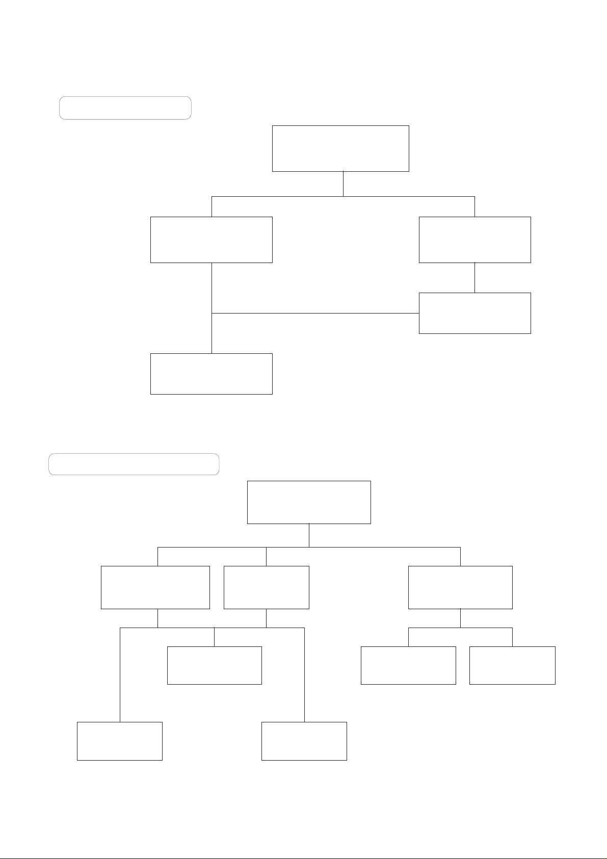
NO RASTER
CHECK +B
at D821 cathode
Is the voltage at pin37
& 12 of IC501 8V?
Check
FUSE of AC line
Check the voltage
of C805
Check the voltage
of pin9
Check pin40
of IC501(H-out)
Check Q402
collector waveform
Check T401
& each pin voltage
Is the voltage at pin37
& 12 of IC501 8V?
Check &replace
IC501
Check &replace
IC501
Check &replace
IC501
Check the in/out
of IC841
Check u-COM
pin1 low?
Check /replace
Q802
Check /replace
D804,IC801,R801,802
Check /replace
Fuse,DB801,IC801
Check /replace
DB801,R851
Normal Abnormal
Yes
Yes
Yes
Yes
No
No
No
No
No
No
OK
254~380V
Open
0V
Page 2
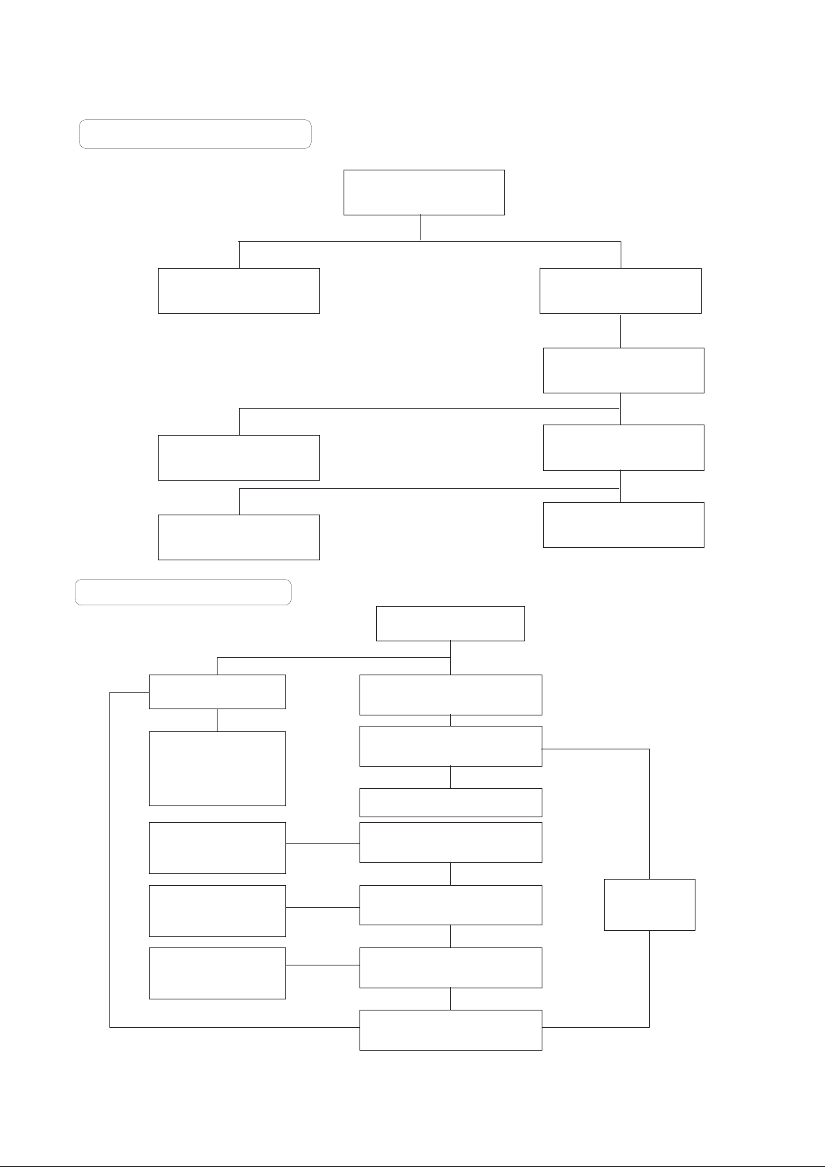
NO TELETEXT
Check the
voltage of IC701 pin19
Check
IC701& IICBus Line
Check 5V Supply
Line of IC701
0V
OK
OK
Check
CVBS signal
at IC701 pin9
Check / Replace
Q701, X701, & IC501
Not OK
OK
NO RASTER / SOUND OK
Check the
Heater voltage of CPT
(6 ≠ 6.5Vrms)
Check
FR704, FR901
P302, & P903
Check
FBT T701
Check the
Heater pulse of FBT
T701
Check
Ik Current of
IC501, pin18
Not OK
OK Not OK
Check/Replace
CPT Board
Components
Check
IC501, ZD904
P501, & P902
OK Not OK
OK
Check
HV, Screen voltage of
CPT
Check
FBT T701
Not OK
Page 3
NO SOUND / PICTURE OK
Check the voltage of SMPS
25V at pin5 of IC601
Check the voltage
swing of pin2 of IC501
Normal(20~25V)Abnormal
Check demodulated
signal of pin15 of IC501
Check demodulated
of input pin of IC601
Check/Replace IC01
Check/Replace of
FR824,D824,FR601
Check/Replace IC501
Check/Replace IC601
NO PICTURE / NO SONUD
Is any OSD displayed?
Check receiving system in MENU
& excute Auto-program.
Yes
OK
Not OK
Check IC01 pin9,10
(V-Sync, H-Sync)
Check IC01 pin36,37
(XLC, EXLC)
& IC01
No
Go to
NO SOUND /
PICTURE OK
Does the Auto-program
operate properly.
Store in manual-program MENU
Check 5V, 33V & IIC Bus Line
of TUNER
Is the CVBS signal OK.
( IC501 pin6 )
Check R,G,B signal
at IC501 pin19,20,21
Check
5V, 33V &
IIC Bus Line
Yes
Not OK
Not OK
OK
Check / Replace
TUNER, IC501
Not OK
OK
Check / Replace
CPT Board component
Check
CVBS singal Line
& IC501
Check IC01 pin30,31,32
(R,G,B)
OK
Not OK
Page 4
- 1 -
Y Safety Precautions
1. It is safe to adjust after using insulating transformer
between the power supply line and chassis input to
prevent the risk of electric shock and protect the
instrument.
2. Never disconnect leads while the TV receiver is on.
3. Don't short any portion of circuits while power is on.
4. The adjustment must be done by the correct appliances.
But this is changeable in view of productivity.
5. Unless otherwise noted, set the line voltage to
230Vac
!10%, 50/60Hz.
Y Test Equipment required
1. Multimeter (volt meter)
2. Oscilloscope
:
RF AGC (Automatic Gain Control) Adjustment
The RF AGC was aligned at the time of manufacture for
optimum performance over a wide range conditions.
Readjustment of RF AGC should not be necessary unless
unusual local conditions exist, such as ;
1) Channel interference in a CATV system.
2) Picture bending and/or color beats, which are unusually
due to excessive RF signal input when the receiver is too
close to a transmitting tower or when the receiver is
connected to an antenna distribution system where the RF
signal has been amplified. In this case, the input signal
should be attenuated (with pad or filter) to a satisfactory
level.
3) Picture noise caused by "broadcast noise" or weak signal.
If the broadcast is "clean" and the RF signal is at least
1mV (60dBu), the picture will be noise free in any area.
Adjusting RF AGC to one end of rotation will usually cause a
relatively poor signal to noise ratio;
Adjusting to the other end of rotation will usually cause a
degradation of over load capabilities resulting in color beats or
adjacent channel interference.
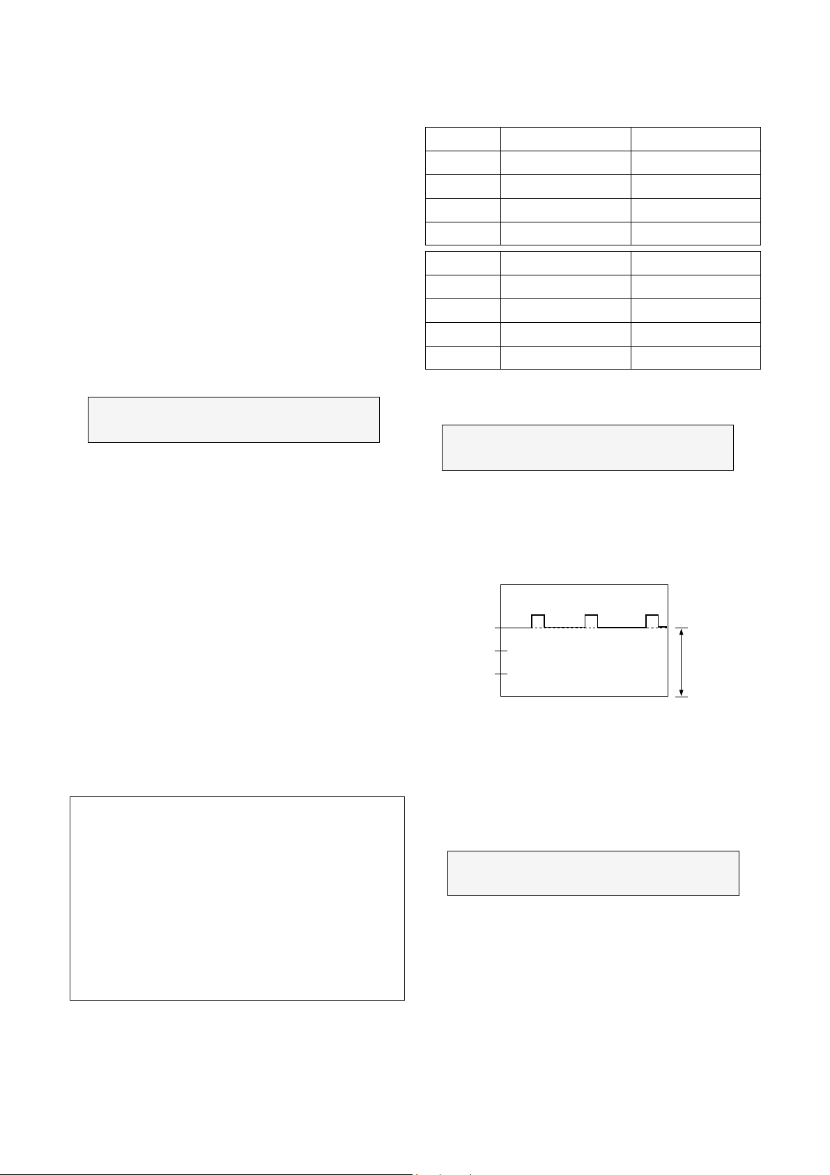
: Screen Voltage Adjustment
1) Press TV/AV Key to get AV Mode.
2) Connect the probe of oscilloscope to the RK (Red
Cathode) of CPT Board.
3) Adjust Screen Volume of FBT so that the waveform is the
same as below figure.
: Focus Adjustment
NOTE: This adjustment should be performed after warming
up for 10 minutes.
1) Tune the TV set to receive an inactive channel station.
2) Adjust the Focus control of FBT for best overall focus.
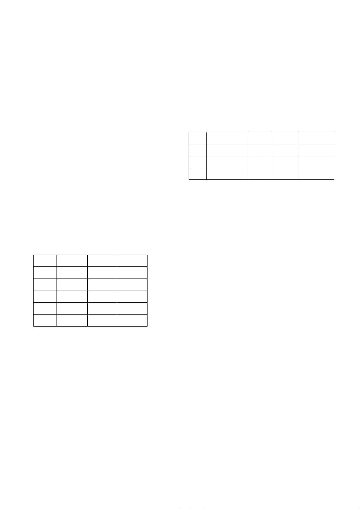
Adjustment
1. Connect RF signal (65dB!0.2dB) and turn on the TV.
[ Standard adjustment Channel
- EU 05 Ch. (f
rf = 175.25MHz) : CK, CL, CB
- EU 41 Ch. (f
rf = 631.25MHz) : CI
2. Press OK buttons on TV set and Remote Controller at the
same time to get into SVC-0 mode.
3. Press Channel UP/DOWN button on the Remote Controller
several times to find AGC??.
4. Press Volume UP/DOWN button until the AGC Voltage is
the same as the Table below.
5. Press OK(Y) button to memorize the data.
Test Point : AGC TP (J05)
Adjust : Remote Control
Test Point : RK (Red Cathode of CPT Board)
Adjust : Screen Control of FBT
Model
System
Tuner P/N
Marker
AGC Voltage
CK-
PAL/SECAM-B/G,D/K
6700VPF005B
LGEC
2.3! 0.1V
CL-
PAL/SECAM-B/G,LL'
6700VPF005A
LGEC
2.3! 0.1V
Model
System
Tuner P/N
Marker
AGC Voltage
CB-
PAL-B/G
6700VPF005B
LGEC
2.3! 0.1V
CI-
PAL-I/I
6700VPF005A
LGEC
2.1! 0.1V
Test Point : Observing Display
Adjust : Focus control of FBT
ADJUSTMENT
The waveform of AV Mode
V
200
150
100
50
GND
50V/DIV. 0.5usec.
BlackLevel(DC)
150V
Page 5
- 2 -
: Deflection Data Adjustment (Line SVC-1)
NOTE: To enter SVC mode, press "OK" buttons on both TV set
and the Remote control at the same time.
1. Preparation for Deflection Adjustment
1) At SVC mode, press the Yellow colored button.
If the Remote Controller doesn't have the Yellow button, you
should use a Service Remote Control (105-201G) and press
SVC button.
And then, deflection data adjustment OSD (SVC1 mode) will
be displayed.
2) Press Channel UP/DOWN button for desirous function
Adjustment.
3) Press Volume UP/DOWN button to adjust the data.
2. Deflection Adjustment Procedure
1) Vertical Adjustment
Slect VS and adjust until the mechanical center of CPT and
that of screen coincides and select VA and adjust to coincide
the inner circle of screen with outer frame of CPT.
2) Horizontal Adjustment
Select HS and adjust until the mechanical center of CPT and
that of screen coincides.
3) Vertical S Correction Adjustment
Select SC and adjust until top-bottom side pincushion are
equal.
4) Press OK(Y) button to memorize the data.
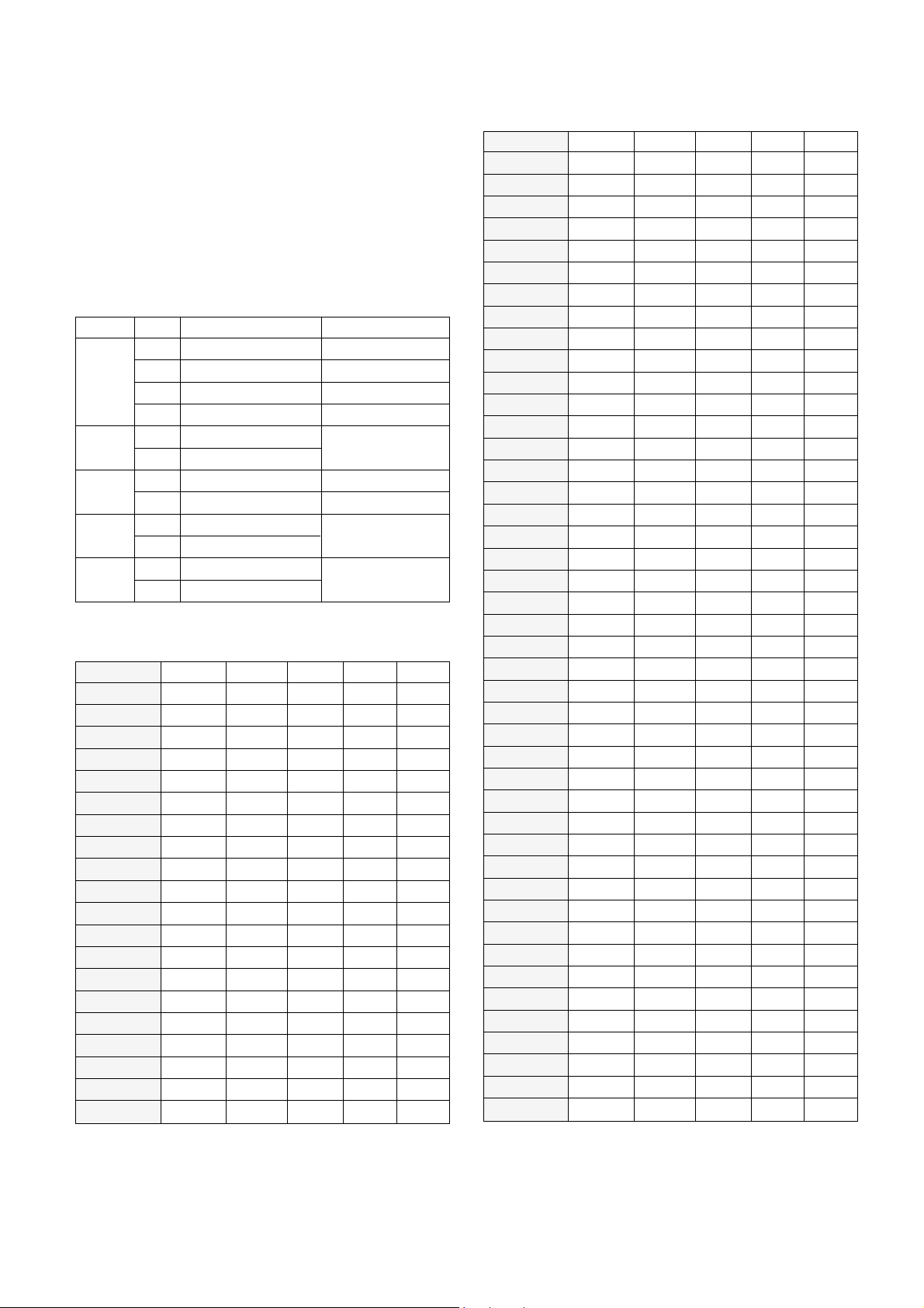
3. Deflection Initial Setup Data
: White Balance Adjustment.(LINE SVC-0)
NOTE : This adjustment should be performed after screen voltage
adjustment.
1) Tune the TV set to receive an 100% white pattern.
2) Press OK(Y) buttons on TV set and remote controller at the
same time to get into SVC mode.
3) Press PSM(RED) button on remote controller. (Standard
picture)
4) Press Channel UP/DOWN button for desirous function
adjustment.
5) Adjust VOL+ or VOL- button for GG031.
6)
Adjust VOL+ or VOL-button in each status of "Rg--"/"Bg--" for
X=293
!
8, Y=295!8 with color analyzer.
7) Press OK
(Y)
button to memorize the adjustment data.
Status
RG
GG
BG
Range
0~63
0~63
0~63
Initial Data
28
31
25
RemarkAdjustment
R-Drive
G-Drive
B-Drive
VL
VS
VA
HS
SC
38
23
40
30
11
Status Default
38
23
40
30
11
21" SEB
38
19
36
32
11
20" SEB
Page 6
- 3 -
: OPTION Adjustment (SVC MODE:OPTION-1,
OPTION-2)
NOTE: When the EEPROM has been replaced, the Option data
should be restored as the function of individual system
and specification.
1) Press OK buttons on both TV set and Remote Controller at
the same time to get into SVC mode.
2) Press the Yellow button several times to find OPTION-1 or
OPTION-2.
3) Input the correspond OPTION data referring to Table below
with the numeric buttons 0~9.
Table 1. OPTION 1 Function
Table 2. Specifications for OPTION-1 data
20
21
22
23
24
25
26
27
28
29
30
31
32
33
34
35
36
37
38
39
40
41
42
43
44
45
46
47
48
49
50
51
52
53
54
55
56
57
58
59
60
61
62
63
CL-Model
CK-Model
CB-Model
CI-Model
for BUYER'S
request
AV 2
TOP
ACMS
HOTEL
SYSTEM
Option
OPTION Data SYSTEM HOTEL ACMS TOP AV 2
Code
00
01
10
11
0
1
0
1
0
1
0
1
0
1
2
3
4
5
6
7
8
9
10
11
12
13
14
15
16
17
18
19
00
00
00
00
00
00
00
00
00
00
00
00
00
00
00
00
01
01
01
01
0
0
0
0
0
0
0
0
1
1
1
1
1
1
1
1
0
0
0
0
0
0
0
0
1
1
1
1
0
0
0
0
1
1
1
1
0
0
0
0
0
0
1
1
0
0
1
1
0
0
1
1
0
0
1
1
0
0
1
1
0
1
0
1
0
1
0
1
0
1
0
1
0
1
0
1
0
1
0
1
Function Remark
B+L (BG+LL')
B+D (BG+DK)
BG
II
W/O HOTEL
For HOTEL
ACMS Off
ACMS On
TOP Off
TOP On
AV 2 Off
AV 2 On
OPTION Data SYSTEM SCART EYE UBB AV2
01
01
01
01
01
01
01
01
01
01
01
01
10
10
10
10
10
10
10
10
10
10
10
10
10
10
10
10
11
11
11
11
11
11
11
11
11
11
11
11
11
11
11
11
0
0
0
0
1
1
1
1
1
1
1
1
0
0
0
0
0
0
0
0
1
1
1
1
1
1
1
1
0
0
0
0
0
0
0
0
1
1
1
1
1
1
1
1
1
1
1
1
0
0
0
0
1
1
1
1
0
0
0
0
1
1
1
1
0
0
0
0
1
1
1
1
0
0
0
0
1
1
1
1
0
0
0
0
1
1
1
1
0
0
1
1
0
0
1
1
0
0
1
1
0
0
1
1
0
0
1
1
0
0
1
1
0
0
1
1
0
0
1
1
0
0
1
1
0
0
1
1
0
0
1
1
0
1
0
1
0
1
0
1
0
1
0
1
0
1
0
1
0
1
0
1
0
1
0
1
0
1
0
1
0
1
0
1
0
1
0
1
0
1
0
1
0
1
0
1
Page 7

- 4 -
Table 3. OPTION 2 Function
Table 4. Specifications for OPTION-2 data
0
1
2
3
4
5
6
7
8
9
10
11
12
13
14
15
16
17
18
19
20
21
22
23
24
25
26
27
28
29
30
31
STEREO Option
TUNER1
EYE
GAME
D/K
NICAM
Language
Option Code
0
1
0
1
0
1
0
1
0
1
Function Remark
OSD Lang. (14)
OSD Lang. (5)
D/K NICAM Off
D/K NICAM System
W/O GAME
With GAME function
EYE Off
EYE On
LGEC TUNER
PHILIPS TUNER
OPTION Data Lang.
D/K NICAM
GAME EYE
TUNER1
0
0
0
0
0
0
0
0
0
0
0
0
0
0
0
0
1
1
1
1
1
1
1
1
1
1
1
1
1
1
1
1
0
0
0
0
0
0
0
0
1
1
1
1
1
1
1
1
0
0
0
0
0
0
0
0
1
1
1
1
1
1
1
1
0
0
0
0
1
1
1
1
0
0
0
0
1
1
1
1
0
0
0
0
1
1
1
1
0
0
0
0
1
1
1
1
0
0
1
1
0
0
1
1
0
0
1
1
0
0
1
1
0
0
1
1
0
0
1
1
0
0
1
1
0
0
1
1
0
1
0
1
0
1
0
1
0
1
0
1
0
1
0
1
0
1
0
1
0
1
0
1
0
1
0
1
0
1
0
1
Page 8

- 5 -
PURITY & CONVERGENCE ADJUSTMENT
Caution:
Convergence and Purity have been factory aligned. Do not
attempt to tamper with these alignments.
However, the effects of adjacent receiver components, or
replacement of picture tube or deflection yoke may require the
need to readjust purity any convergence.
Y Purity Adjustment
This procedure DOES NOT apply to bonded yoke and picture
tube assemblies.
The instrument should be at room temperature (60 degrees F or
above) for six (6) hours and be operating at low beam current
(dark background) for approximately 20 to 30 minutes before
performing purity adjustments.
CAUTION: Do not remove any trim magnets that may be
attached to the bell of the picture tube.
1. Remove the AC power and disconnect the internal
degaussing coil.
2. Remove the yoke from the neck of the picture tube.
3. If the yoke has the tape version beam bender, remove it and
replace it with a adjustable type beam bender (follow the
instructions provided with the new beam bender)
4. Replace the yoke on the picture tube neck, temporarily
remove the three (3) rubber wedges from the bell of the
picture tube and then slide the yoke completely forward.
5. Reconnect the internal degaussing coil.
6. Position the beam bender locking rings at the 9 o'clock
position and the other three pairs of tabs (2,4 and 6 pole
magnets) at the 12 o'clock position.
7. Perform the following steps, in the order given, to prepare the
receiver for the purity adjustment procedure.
a. Face the receiver in the "magnetic north" direction.
b. Externally degauss the receiver screen with the television
power turned off.
c. Turn the television on for approximately 10 seconds to
perform internal degaussing and then turn the TV off.
d. Unplug the internal degaussing coil. This allows the
thermistor to cool down while you are performing the purity
adjustment. DO NOT MOVE THE RECEIVER FROM ITS
"MAGNETIC NORTH" POSITION.
e. Turn the receiver on and obtain a red raster by increasing
the red bias control (CW) and decreasing the bias controls
for the remaining two colors (CCW).
f. Attach two round magnets on the picture tube screen at 3
o'clock and 9 o'clock positions, approximately one (1) inch
from the edge of the mask (use double-sided tape).
DEFLECTION YOKE
PURITY &CONVERGENCE
MAGNET ASSEMBLY
RUBBER
WEDGES
GLASS CLOTH TAPE
PURITY MAGNET
6-POLE
4-POLE
4-POLE
MAGNET
CONVERGENCE MAGNET ASSEMBLY
6-POLE
MAGNES
PURITY MAGNET(2-POLE)
X-AXIS YOKE
POSITIONING
(L/R PURITY)
6-POLE
MAGNETS
CONVERGENCE MAGNET ASSEMBLY
Page 9

- 6 -
8. Referring to above, perform the following two steps:
a. Adjust the yoke Z-axis to obtain equal blue circles.
b. Adjust the appropriate beam bender tabs to obtain correct
purity (four equal circles).
9. After correct purity is set, tighten the yoke clamp screw and
remove the two screen magnets.
10. Remove the AC power and rotate the receiver 180 degrees
(facing "magnetic south").
11. Reconnect the internal degaussing coil.
12. Turn the receiver on for 10 seconds (make sure the receiver
came on) to perform internal degaussing, and then turn the
receiver off.
13. Unplug the internal degaussing coil.
14. Turn on the receiver and check the purity by holding one (1)
round magnet at the 3 o'clock and a second round magnet at
9 o'clock position. If purity is not satisfactory, repeat steps 8
through 14.
15. Turn off the receiver and reconnect the internal degaussing
coil.
Y Convergence Adjustment
Caution: This procedure DOES NOT apply to bonded yoke and
picture tube assemblies.
Do not use screen magnets during this adjustment
procedure. Use of screen magnets will cause an
incorrect display.
1. Remove AC power and disconnect the internal degaussing
coil.
2. Apply AC Power and set the brightness to the Picture Reset
condition. Set the Color control to minimum.
3. Apply 8V to the pin42 of IC501.
4. Adjust the Red, Green and Blue Bias controls to get a dim
white line.
5. Remove the AC power and 8V from the pin42 of IC501.
6. Reconnect the internal degaussing coil and apply AC power.
7. Turn the receiver on for 10 seconds to perform internal
degaussing and then turn the receiver off again.
8. Unplug the internal degaussing-coil.
9. Turn on the receiver, connect a signal generator to the VHF
antenna terminal and apply a crosshatch signal.
Caution: During the convergence adjustment procedure, be
very careful not to disturb the purity adjustment tabs
are accidentally move, purity should be confirmed
before proceeding with the convergence adjustments.
Note:
Make sure the focus is set correctly on this instrument
before proceeding with the following adjustment.
10. Converge the red and blue vertical lines to the green vertical
line at the center of the screen by performing the following
steps (below TABLE).
a. Carefully rotate both tabs of the 4-pole ring magnet
simultaneously in opposite directions from the 12 o'clock
position to converge the red and blue vertical lines.
b. Carefully rotate both tabs of the 6-pole ring magnet
simultaneously in opposite directions form the 12 o'clock
position to converge the red and blue (now purple)
vertical lines with the green vertical line.
11. Converge the red and blue horizontal with the green line at
the center of the screen by performing the following steps.
(below TABLE)
a. Carefully rotate both tabs of the 4-pole ring magnet
simultaneously in the same direction (keep the spacing
between the two tabs the same) to converge the red and
blue horizontal lines.
b. Carefully rotate both tabs of the 6-pole ring magnet
simultaneously in same direction (keep the spacing
between the two tabs the same) to converge the red and
blue (now purple) horizontal lines with the green
horizontal line.
c. Secure the tabs previsouly adjusted by locking them in
place with the locking tabs on the beam bender.
MAGNETS
RED RED
1.ADJUST YOKE Z-AXIS FIRST
TO GET EQUAL BLUE
COLOR CIRCLES
2 .ADJUST BEAM BENDER 2 POLE
MAGNET TO GET FOUR EQUAL
COLOR CIRCLES
Page 10
- 7 -
RING
PAIRS
4
POLE
ROTATION DIRECTION
OF BOTH TABS
OPPOSITE
SAME
OPPOSITE
SAME
MOVEMENT OF RED
AND BLUE BEAMS
B B
RR
OR
OR
B R B R
OR
B
R
B
R
B R
OR
B
R
6
POLE
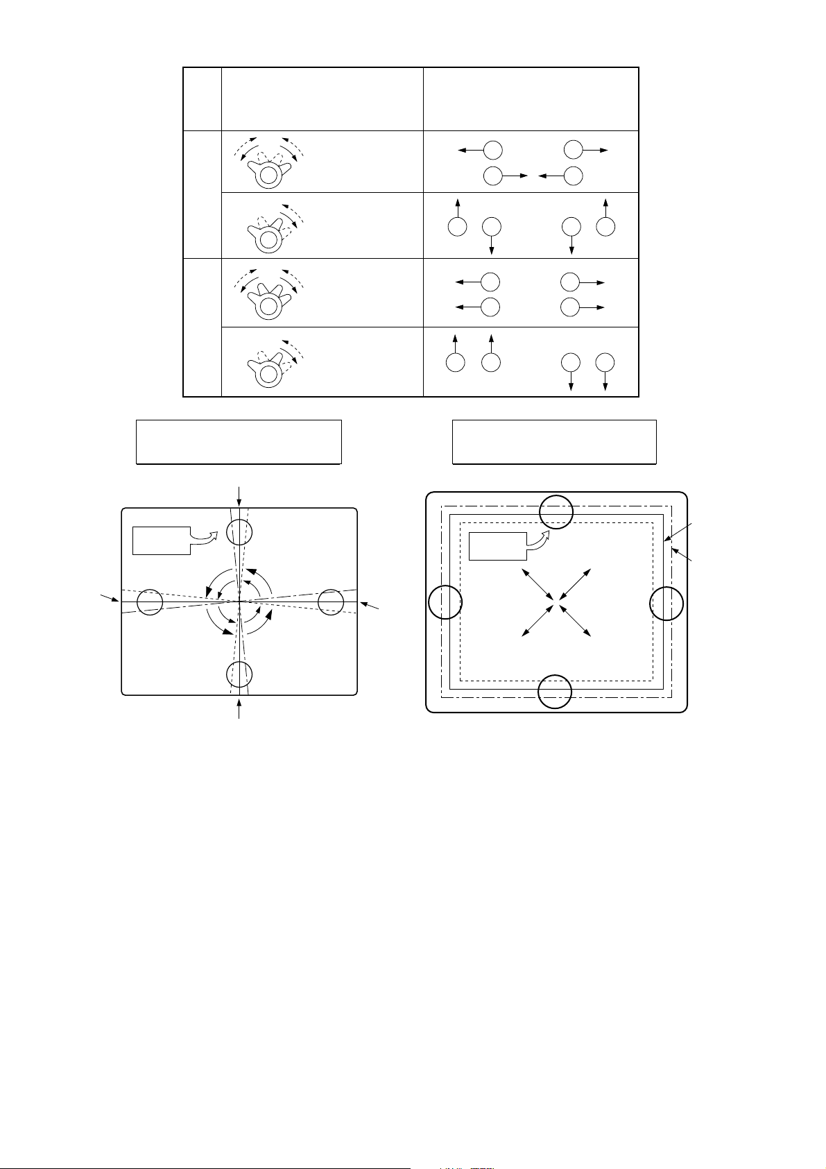
12. While watching the 6 o'clock positions on the screen, rock the
front of the yoke in a vertical (up/down) direction to converge
the red and blue vertical lines. (Fig upper left)
13. Temporarily place a rubber wedge at the 12 o'clock position
to hold the vertical position or the yoke.
14.
Check the 3 o'clock and 9 o'clock areas to confirm that the red
and blue horizontal lines are converged.
If the lines are not converged, slightly offset the vertical tilt of the
yoke (move the rubber wedge if necessary) to equally balance the
convergence error of the horizontal lines at 3 o'clock and 9 o'clock
and the vertical lines at 6 o'clock and 12 o'clock.
15. Place a 1.5 inch piece of glass tape over the rubber foot at
the rear of the 12 o'clock wedge.
16. While watching the 6 o'clock and 12 o'clock areas of the
screen, rock the front of the yoke in the horizontal (left to
right) motion to converge the red and blue horizontal lines.
(Fig. upper right)
17. Temporarily place a rubber wedge at the 5 o'clock and 7
o'clock positions to hold the horizontal position of the yoke.
18. Check the 3 o'clock and 9 o'clock areas to confirm that the
red and blue vertical lines are converged. If the lines are not
converged, slightly offset the horizontal tilt of the yoke (move
the temporary rubber wedges if necessary) to equally
balance the convergence error of the horizontal lines at 6
o'clock and 12 o'clock and the vertical lines at 3 o'clock and 9
o'clock.
19. Using a round magnet confirm purity at the center, right and
left sides and corners. See Purity Adjustment Procedure.
20. Reconfirm convergence and apply a 1.5 inch piece of glass
tape over the rubber foot at the rear of the 5 o'clock and the 7
o'clock wedges.
RED
BLUE
RED BLUE
BLUE
RED
GREEN
GREEN
BLUE RED
GREEN
GREEN
ADJUSTMENT
VIEWING
AREA
UP/DOWN ROCKING OF THE YOKE
CAUSES OPPOSITE ROTATION OF RED
AND BLUE RASTERS
ADJUSTMENT
VIEWING
AREA
RED
RED
GREEN
TV
SCREEN
LEET/RIGHT ROCKING OF THE YOKE
CAUSES OPPOSITE SIZE CHANGE OF
THE RED AND BLUE RASTERS
UP/DOWN ROCKING OF THE YOKE
CAUSES OPPOSITE ROTATION OF RED
AND BLUE RASTERS
LEFT/RIGHT ROCKING OF THE YOKE
CAUSES OPPOSITE SIZE CHANGE OF THE
RED AND BLUE RASTERS
Page 11

- 1 -
943
510
511
150
170
520
104
300
320
330
310
912
120
P801
913
103
102
112
153
400
EXPLODED VIEW
Page 12

- 2 -
EXPLODED VIEW PARTS LIST
LOCA. NO PART NO DESCRIPTIONS
102 341-721E HOLDER,D-COIL(FOR SAFA,L=65)
103 341-721F HOLDER,D-COIL(FOR SAFA,L=130)
104 343-B52A SUPPORTER,PCB
*112
112-C20S (NE) CPT SET A48ECR141X 20"
112-C21G (NE) CPT SET A51EER131X29 21"
120 120-C93H SPEAKER,GENERAL 8 OHM 3/5W 80DB 90
150
150-D02M COIL,DEGAUSSING,CU 20"60T 15OHM
150-D02N COIL,DEGAUSSING,CU 21"60T 12OHM
170
170-A01J CPT EARTH 20"
170-A01K CPT EARTH 21"
3106V00050C CABINET UNIT SCK20F80
300
3106V00061M CABINET UNIT SCK21F80
3106V00050N CABINET UNIT SCL20F80
3106V00061L CABINET UNIT SCL21F80
310
5020V00179B BUTTON,CONTROL 20"
5020V00171B BUTTON,CONTROL 21"
320 320-062E SPRING,KNOB
330
5020V00180B BUTTON,POWER 20"
5020V00170B BUTTON,POWER 21"
400
3809V00073K BACK COVER ASSY 20"
3809V00089K BACK COVER ASSY 21"
6871VMM277B PWB ASSY,MAIN(PC-81A)7,21,04 *MUR-MK 20"
6871VMM277D PWB ASSY,MAIN(PC-81A)7,17,04 *MUR-MK 20"
6871VMM277A PWB ASSY,MAIN(PC-81A)7,21,04 *MUR-MK 21"
520 6871VMM277C PWB ASSY,MAIN(PC-81A)7,17,04 *MUR-MK 21"
6871VMM273A PWB ASSY,MAIN(PC-81A)7,01,04 *NE-FS 20"
6871VMM273C PWB ASSY,MAIN(PC-81A)7,01,04 *NE-FS 21"
6871VMM273B PWB ASSY,MAIN(PC-81A)7,05,04 *NE-FS 20"
912 1PRF0302816 SCREW,TAP D3 L12
913
332-057B SCREW ASSY,HEXAGON HEAD 20"
332-057J SCREW ASSY,HEXAGON HEAD 21"
943 1PTF0403116 SCREW,TRUSS HEAD D4 L16
P801 174-009E CORD,POWER(W/HOLD,HOUSING,L=200,4.0
The components identified by mark are
critical for safety.
Replace only with part number specified.
The parts which are marked with " *" are
Local parts.
LG Electronics North of England LTD.
BRITLEY ROAD, WASHINGTON
TYNE & WEAR NE38 9DE
UNITED KINGDOM
LEGNE CTV SPARE PARTS DEPT.
TEL : (44-191) 418-3355
FAX : (44-191) 418-3351
We are supposed to supply the local parts for CTV spares to you from U.K.
In case of the local parts marked with "NE" on your SERVICE MANUAL,
please place an order to the above address in U.K.
ADDRESS
DEPARTMENT
Page 13

REPLACEMENT PARTS LIST
The components identified by mark is
critical for safety.
Replace only with part number specified.
LOCA. NO PART NO DESCRIPTION
IC01
IC02
IC03
IC201
IC301
IC501
IC601
IC603
IC604
IC701
IC801
IC802
IC803
IC804
IC805
IC901
Q01
Q02
Q04
Q101
Q103
Q111
Q112
Q115
Q201
Q202
Q203
Q231
Q252
Q401
Q402
Q501
Q502
Q503
Q504
Q505
Q51
Q510
Q512
Q541
Q542
Q601
Q691
Q701
Q801
Q802
Q804
Q805
0ISO881819A
0IAL241600B
0ISS754200A
0IHA405200A
0IPH835150A
0IPH884212A
0ISG200600A
0ISA701600A
0ITF448800A
0IPH528100H
0ISK570700A
0ISH123200B
0ISS780500J
0ISS780800H
0IKE780500K
0IPH610700A
0TR387500AA
0TR102009AG
0TR102009AG
0TR102009AG
0TR102009AG
0TR387500AA
0TR387500AA
0TR388109AA
0TR387500AA
0TR387500AA
0TR387500AA
0TR150400BA
0TR387500AA
0TR320709AA
0TR249900AA
0TR387500AA
0TR150400BA
0TR150400BA
0TR387500AA
0TR387500AA
0TR945009AA
0TR150400BA
0TR387500AA
0TR387500AA
0TR387500AA
0TR102009AG
0TR387500AA
0TR387500AA
0TR102709AA
0TR120209AD
0TR945009AA
0TR320209AA
IC,LG8818-19A(CXP86441-533S) 52SD
IC,AT24C16-10PC 8D EEPROM 16K
IC,KA7542Z RESET TO92 TP 4.2V
IC,CD4052B 16P DIP DIFF-4-CH MUX
IC,TDA8351/N5 9P,SIP BK V/OUT(W/O
IC,TDA8842(S1)/N2 56P,SDIP BK MUL
IC,TDA2006,SOUND
IC,LA7016 8S ANALOG S/W
IC,U4488B 16DIP BK SIF+AM DEMODUL
IC,SAA5281ZP/H 52SDIP BK TXT DECO
IC,STR/S5707(LF.953) 9P SMPS-CNTR
IC,PC123 FY2PHOTO COUPLER
IC,KA78L05AZ TO-92 TP 5V REGULATO
IC,KA78R08 4P,TO-220F BK LOW DROP
IC,KIA7805PI 3P(TO-220IS) 5V,1A
IC,TDA6107Q SIP9 BK VIDEO OUT AMP
TR,2SC3875S(ALY)
TR,KRC102S SOT-23
TR,KRC102S SOT-23
TR,KRC102S SOT-23
TR,KRC102S SOT-23
TR,2SC3875S(ALY)
TR,2SC3875S(ALY)
TR,KTC3881
TR,2SC3875S(ALY)
TR,2SC3875S(ALY)
TR,2SC3875S(ALY)
TR,2SA1504S(ASY)
TR,2SC3875S(ALY)
TR,KTC3207,TP(KTC2482)
TR,KTD2499 TO-3P(H)IS
TR,2SC3875S(ALY)
TR,2SA1504S(ASY)
TR,2SA1504S(ASY)
TR,2SC3875S(ALY)
TR,2SC3875S(ALY)
TR,KSC945C-Y,TP,SS
TR,2SA1504S(ASY)
TR,2SC3875S(ALY)
TR,2SC3875S(ALY)
TR,2SC3875S(ALY)
TR,KRC102S SOT-23
TR,2SC3875S(ALY)
TR,2SC3875S(ALY)
TR,KTC1027-Y TP(KTC2235),KEC
TR,KSR1202 TP SAMSUNG TO92S
TR,KSC945C-Y,TP,SS
TR,KTC3202-TP-Y (KTC1959)KEC
LOCA. NO PART NO DESCRIPTION
DB801
D101
D111
D112
D301
D402
D403
D501
D502
D503
D504
D505
D506
D507
D508
D509
D510
D602
D701
D702
D703
D704
D741
D742
D743
D744
D802
D803
D804
D805
D806
D821
D823
D824
D827
D901
D902
D903
D904
ZD01
ZD101
ZD102
ZD231
ZD501
ZD741
ZD742
ZD801
ZD904
C02
0DD260000BD
0DD414809ED
0DD859009AA
0DD859009AA
0DD414809ED
0DD150009CA
0DD414809ED
0DD414809ED
0DD414809ED
0DD414809ED
0DD414809ED
0DD414809ED
0DD414809ED
0DD859009AA
0DD859009AA
0DD859009AA
0DD859009AA
0DD414809ED
0DD414809ED
0DD414809ED
0DD414809ED
0DD414809ED
0DD060009AC
0DD200009AH
0DD060009AC
0DD414809ED
0DD100009AM
0DD060009AC
0DD060009AC
0DD060009AC
0DD100009AM
0DD300009AC
0DD200009AH
0DD150009CA
0DD060009AC
0DD400309AD
0DR210009AA
0DR210009AA
0DR210009AA
0DZ560009CF
0DZ560009CF
0DZ330009DF
0DZ120009AF
0DZ180009AG
0DZ820009AH
0DZ820009AH
0DZ680009BB
0DZ750009AG
0CE475DK618
DIODE,BRIDGE D2SBA60
DIODE,DS4148
DIODE,MA859
DIODE,MA859
DIODE,DS4148
DIODE,RGP15J
DIODE,DS4148
DIODE,DS4148
DIODE,DS4148
DIODE,DS4148
DIODE,DS4148
DIODE,DS4148
DIODE,DS4148
DIODE,SILICON MA859
DIODE,SILICON MA859
DIODE,SILICON MA859
DIODE,SILICON MA859
DIODE,DS4148
DIODE,DS4148
DIODE,DS4148
DIODE,DS4148
DIODE,DS4148
DIODE,TVR06J 0.6A/600V 250NS
DIODE,RU2AMV
DIODE,TVR06J 0.6A/600V 250NS
DIODE,DS4148
DIODE,EU1ZV
DIODE,TVR06J 0.6A/600V 250NS
DIODE,TVR06J 0.6A/600V 250NS
DIODE,TVR06J 0.6A/600V 250NS
DIODE,EU1ZV
DIODE,RU3AMV
DIODE,RU2AMV
DIODE,RGP15J
DIODE,TVR06J 0.6A/600V 250NS
DIODE,IN4003A RECT
DIODE,RECTIFIER BAV21 DO-35 200V
DIODE,RECTIFIER BAV21 DO-35 200V
DIODE,RECTIFIER BAV21 DO-35 200V
DIODE,ZENER MTZJ5.6B TP ROHM-K
DIODE,ZENER MTZJ5.6B TP ROHM-K
DIODE,ZENER MTZJ33B TP ROHM-K
DIODE,ZENER MTZJ12B TP ROHM-K
DIODE,ZENER MTZJ18B TP ROHM-K
DIODE,ZENER MTZJ8.2B TP ROHM-K
DIODE,ZENER MTZJ8.2B TP ROHM-K
DIODE,ZENER MTZJ6.8B TP ROHM-K
DIODE,ZENER MTZJ7.5B TP ROHM-K
C,ELECTROLYTIC 4.7UF STD 50V M
IC
TRANSISTOR
DIODE
CAPACITOR
- 18 -
Page 14

- 19 -
LOCA. NO PART NO DESCRIPTION
C08
C09
C101
C104
C105
C106
C107
C108
C11
C111
C112
C114
C116
C12
C20
C201
C202
C203
C205
C207
C208
C22
C23
C233
C252
C301
C302
C303
C304
C305
C306
C307
C308
C401
C403
C405
"(21")
C406
C407
C409
C410
C501
C502
C504
C507
C510
C513
C514
C516
C517
C518
C521
0CE225DK618
0CE106DF618
0CE475DK618
0CE226DF618
0CE476DK618
0CN1040K949
0CN2230H949
0CE107DH618
0CE106DF618
0CN1030F679
0CN1030F679
0CE476DF618
0CN1030F679
0CE335DK618
0CE107DF618
0CE225DK618
0CE225DK618
0CE2251K636
0CE476DF618
0CE106DF618
0CE475DK618
0CN2230H949
0CE104DK618
0CE227DF618
0CE475DK618
0CN1010K519
0CN1040K949
0CE226DN618
0CE476DN618
0CQ3321N509
0CQ1041N509
0CQ1531N509
0CQ1031N509
181-013C
0CK1020W515
181-015H
181-015P
0CN3310K519
0CE225DP618
0CE105DP618
0CE105DP618
0CE476DF618
0CE106DH618
0CQ1041N509
0CE225DK618
0CE107DF618
0CQ1042K439
0CQ1042K439
0CN2230H949
0CN2230H949
0CN2230H949
0CC2710K415
C,ELECTROLYTIC 2.2UF STD 50V M
C,ELECTROLYTIC 10UF STD 16V M
C,ELECTROLYTIC 4.7UF STD 50V M
C,ELECTROLYTIC 22UF STD 16V M
C,ELECTROLYTIC 47UF STD 50V M
C,TUBULA(HIGH DIELE) 0.1M 50V Z
C,TUBULA(HIGH DIELE) 22000P 25V Z F
C,ELECTROLYTIC 100UF STD 25V M
C,ELECTROLYTIC 10UF STD 16V M
C,TUBULA 10000P 16V M
C,TUBULA 10000P 16V M
C,ELECTROLYTIC 47UF STD 16V M
C,TUBULA 10000P 16V M
C,ELECTROLYTIC 3.3UF STD 50V M
C,ELECTROLYTIC 100UF STD 16V M
C,ELECTROLYTIC 2.2UF STD 50V M
C,ELECTROLYTIC 2.2UF STD 50V M
C,ELECTROLYTIC 2.2UF SM 50V M
C,ELECTROLYTIC 47UF STD 16V M
C,ELECTROLYTIC 10UF STD 16V M
C,ELECTROLYTIC 4.7UF STD 50V M
C,TUBULA 22000P 25V Z
C,ELECTROLYTIC 0.1UF STD 50V M
C,ELECTROLYTIC 220UF STD 16V M
C,ELECTROLYTIC 4.7UF STD 50V M
C,TUBULA(HIGH DIELE) 100PF 50V K
C,TUBULA(HIGH DIELE) 0.1M 50V Z
C,ELECTROLYTIC 22UF STD 100V M
C,ELECTROLYTIC 47UF STD 100V M
C,POLYESTER(MYLAR) 0.0033U 100V K
C,POLYESTER(MYLAR) 0.1MF 100V L
C,POLYESTER(MYLAR) 0.015MF 100V K
C,POLYESTER(MYLAR) 0.01U 100V K
C,MPP 200V 0.39uF J
C,CERAMIC(HIGH DIELE) 1000PF 500V K
C,MPP 1600V 0.0082uF H
C,MPP 1600V 0.0075uF H
C,TUBULA(HIGH DIELE) 330P 50V K
C,ELECTROLYTIC 2.2UF STD 160V M
C,ELECTROLYTIC 1UF STD 160V M
C,ELECTROLYTIC 1UF STD 160V M
C,ELECTROLYTIC 47UF STD 16V M
C,ELECTROLYTIC 10UF STD 25V M
C,POLYESTER(MYLAR) 0.1MF 100V L
C,ELECTROLYTIC 2.2UF STD 50V M
C,ELECTROLYTIC 100UF STD 16V M
C,POLYESTER(MYLAR) 0.1UF S 50V J
C,POLYESTER(MYLAR) 0.1UF S 50V J
C,TUBULA(HIGH DIELE) 22000P 25V Z F
C,TUBULA(HIGH DIELE) 22000P 25V Z F
C,TUBULA(HIGH DIELE) 22000P 25V Z F
C,CERAMIC(TEMP COMP) 270P 50V J
LOCA. NO PART NO DESCRIPTION
C522
C523
C524
C526
C530
C531
C533
C538
C539
"
C543
C544
C545
C548
C601
C602
C603
C604
C606
C608
C614
C632
C656
C657
C659
C661
C691
C692
C693
C694
C695
C703
C705
C707
C708
C709
C711
C712
C714
C743
C744
C745
C746
C747
C748
C749
C751
C801
C802
C803
C804
C805
0CC2710K415
0CC6200K415
0CQ4731N509
0CE227DF618
0CE225DK618
0CE104DK618
0CE105DK618
0CQ1041N455
0CSZVTA001F
0CSZVTA001G
0CE106DH618
0CQ3342K439
0CE224DK618
0CE684DK618
0CE475DK618
0CE108DJ618
0CQ3921N409
0CE106DH618
0CE475DK618
0CQ1542K439
0CE108DJ618
0CE106DK618
0CE475DK618
0CE107DF618
0CE475DK618
0CE2251K636
0CN1030F679
0CE107DF618
0CE475DK618
0CE475DK618
0CQ4721N509
0CE107DD618
0CX8R20K509
0CQ1042K439
0CQ1042K439
0CQ1042K439
0CE476DF618
0CE476DF618
0CE106DH618
0CK4710W515
0CE106DR618
0CK4710W515
0CE337BH618
0CK4710W515
0CE476DN618
181-009V
0CQ1031N509
0CK10201515
0CK10201515
0CK10201515
0CK10201515
181-001E
C,CERAMIC(TEMP COMP) 270P 50V J
C,CERAMIC(TEMP COMP) 62PF 50V J
C,POLYESTER(MYLAR) 0.047U 100V K
C,ELECTROLYTIC 220UF STD 16V M
C,ELECTROLYTIC 2.2UF STD 50V M
C,ELECTROLYTIC 0.1UF STD 50V M
C,ELECTROLYTIC 1UF STD 50V M
C,POLYESTER(MYLAR) 0.1000UF 100V J
C,TANTALUM 0.6UF 35V K *CK-
C,TANTALUM 2.2UF 25V K *CL-
C,ELECTROLYTIC 10UF STD 25V M
C,POLYESTER(MYLAR) 0.33UF S 50V J
C,ELECTROLYTIC 0.22UF STD 50V M
C,ELECTROLYTIC 0.68UF STD 50V M
C,ELECTROLYTIC 4.7UF STD 50V M
C,ELECTROLYTIC 1000UF STD 35V M
C,POLYESTER(MYLAR) 0.0039U 100V J
C,ELECTROLYTIC 10UF STD 25V M
C,ELECTROLYTIC 4.7UF STD 50V M
C,POLYESTER(MYLAR) 0.15UF S 50V J
C,ELECTROLYTIC 1000UF STD 35V M
C,ELECTROLYTIC 10UF STD 50V M
C,ELECTROLYTIC 4.7UF STD 50V M
C,ELECTROLYTIC 100UF STD 16V M
C,ELECTROLYTIC 4.7UF STD 50V M
C,ELECTROLYTIC 2.2UF SM 50V M
C,TUBULA(HIGH DIELE) 0.01MF 16V M
C,ELECTROLYTIC 100UF STD 16V M
C,ELECTROLYTIC 4.7UF STD 50V M
C,ELECTROLYTIC 4.7UF STD 50V M
C,POLYESTER(MYLAR) 0.0047U 100V K
C,ELECTROLYTIC 100UF STD 10V M
C,TUBULA(T.C) 8.2P 50V K
C,POLYESTER(MYLAR) 0.1UF S 50V J
C,POLYESTER(MYLAR) 0.1UF S 50V J
C,POLYESTER(MYLAR) 0.1UF S 50V J
C,ELECTROLYTIC 47UF STD 16V M
C,ELECTROLYTIC 47UF STD 16V M
C,ELECTROLYTIC 10UF STD 25V M
C,CERAMIC(HIGH DIELE) 470PF 500V K
C,ELECTROLYTIC 10UF STD 250V M
C,CERAMIC(HIGH DIELE) 470PF 500V K
C,ELECTROLYTIC 330UF KME 25V M
C,CERAMIC(HIGH DIELE) 470PF 500V K
C,ELECTROLYTIC 47UF STD 100V M
C,PP 200V 0.047UF K
C,POLYESTER(MYLAR) 0.01U 100V K
C,CERAMIC(HIGH DIELE) 1000P 1KV K
C,CERAMIC(HIGH DIELE) 1000P 1KV K
C,CERAMIC(HIGH DIELE) 1000P 1KV K
C,CERAMIC(HIGH DIELE) 1000P 1KV K
CAPACITOR CE 400V 120UF M
The components identified by mark are
critical for safety.
Replace only with part number specified.
Page 15

- 20 -
LOCA. NO PART NO DESCRIPTION
C806
C807
C808
C809
C81
C810
C811
C812
C813
C814
C820
C822
C823
C824
C826
C827
C829
C832
C837
C843
C844
C853
C904
C905
C906
C907
J162
L01
L02
L03
L04
L05
L06
L101
L102
L111
L112
L113
L201
L202
L241
L250
L251
L254
L257
L258
L290
L291
L292
L293
0CE107DH618
0CE106BN618
0CN1020K519
0CE107DH618
0CE476DF618
0CE227DF618
181-120K
181-120K
181-091Z
0CE108DH618
0CE477DJ618
0CK47101515
181-091Q
0CE108DH618
181-091Q
0CE227DP61A
0CE1071P61A
0CE227DF618
0CE227DF618
0CE477DH618
0CE227DF618
0CQZVBK002D
0CQZVBK002A
0CE106DR618
0CE2261R618
181-033S
0LA0102K119
0LA0102K119
0LA0122K119
0LA0102K119
0LA0102K119
0LA0102K119
0LA0102K119
150-C01G
0LA0102K139
150-C01A
0LA0102K119
0LA0102K119
0LA0102K119
0LA0102K119
0LA1000K119
0LA1000K119
0LA1000K119
0LA0102K119
125-123A
125-022K
0LA1000K119
0LA1000K119
125-123A
125-022K
C,ELECTROLYTIC 100UF STD 25V M
C,ELECTROLYTIC 10UF KME 100V M
C,TUBULA(HIGH DIELE) 1000PF 50V K
C,ELECTROLYTIC 100UF STD 25V M
C,ELECTROLYTIC 47UF STD 16V M
C,ELECTROLYTIC 220UF STD 16V M
CAPACITOR ACT 4KV E 222M TP10
CAPACITOR ACT 4KV E 222M TP10
CAPACITOR 2KV R 821K TP7.5
C,ELECTROLYTIC 1000UF STD 25V M
C,ELECTROLYTIC 470UF STD 35V M
C,CERAMIC(HIGH DIELE) 470P 1KV K
CAPACITOR 1KV R 471K TP5
C,ELECTROLYTIC 1000UF STD 25V M
CAPACITOR 1KV R 471K TP5
C,ELECTROLYTIC 220UF STD 160V M
C,ELECTROLYTIC 100UF SM 160V M
C,ELECTROLYTIC 220UF STD 16V M
C,ELECTROLYTIC 220UF STD 16V M
C,ELECTROLYTIC 470UF STD 25V M
C,ELECTROLYTIC 220UF STD 16V M
C,POLYESTER A.C 275V 0.47UF K
C,POLYESTER A.C 275V 0.1UF M
C,ELECTROLYTIC 10UF STD 250V M
C,ELECTROLYTIC 22M SM 250V M
CAPACITOR 2KV B 122K TP7.5
INDUCTOR,10UH K
INDUCTOR,10UH K
INDUCTOR,12UH K
INDUCTOR,10UH K
INDUCTOR,10UH K
INDUCTOR,10UH K
INDUCTOR,10UH K
COIL,CHOKE 1.0UH A 1105
INDUCTOR,10UH K
COIL,CHOKE 0.29UH A
INDUCTOR,10UH K
INDUCTOR,10UH K
INDUCTOR,10UH K
INDUCTOR,10UH K
INDUCTOR,100UH K
INDUCTOR,100UH K
INDUCTOR,100UH K
INDUCTOR,10UH K
CORE,FERRITE BFD3565R2F
CORE,FERRITE 1UH
INDUCTOR,100UH K
INDUCTOR,100UH K
CORE,FERRITE BFD3565R2F
CORE,FERRITE 1UH
LOCA. NO PART NO DESCRIPTION
L301
L302
L402
L501
L502
L503
L504
L505
L506
L507
L509
L510
L511
L512
L513
L601
L651
L691
L692
L693
L701
L702
L742
L801
L803
L804
L805
L821
L822
L823
L824
L851
L901
T401
T801
FR601
FR704
"(21")
FR741
FR742
FR743
FR823
FR824
FR827
FR901
J80
R01
R03
R08
R09
0LA0102K139
0LA0102K139
150-L01Z
0LA0331K119
0LA0102K119
0LA0681K119
0LA0102K139
0LA0331K119
125-022K
125-123A
125-022K
0LA0102K139
0LA0561K119
0LA0561K119
0LA0561K119
0LA0102K119
0LA0102K119
150-E16C
0LA0102K119
0LA0122K119
0LA0331K119
0LA0102K119
0LA0221K139
125-022K
125-022K
125-123A
125-022K
150-C02F
150-C02F
125-123A
125-123A
150-F06H
150-C02A
151-C02H
151-B06Y
0RF0201K607
180-D02N
180-D02G
0RF0101H609
0RF0470J607
0RF0470J607
0RF0470J607
0RF0470H609
0RF0331K607
180-D02G
0RD1003F609
0RD1000F609
0RD1001F609
0RD4701F609
0RD1002F609
INDUCTOR,10UH K
INDUCTOR,10UH K
COIL,H-LINEARITY 97UH
INDUCTOR,3.3UH K 2.3*3.4 TP
INDUCTOR,10UH K
INDUCTOR,6.8UH K
INDUCTOR,10UH K
INDUCTOR,3.3UH K 2.3*3.4 TP
CORE,FERRITE 1UH
CORE,FERRITE BFD3565R2F
CORE,FERRITE 1UH
INDUCTOR,10UH K
INDUCTOR,5.6UH K
INDUCTOR,5.6UH K
INDUCTOR,5.6UH K
INDUCTOR,10UH K
INDUCTOR,10UH K
COIL,VAR,07S 1B 38.9MHZ
INDUCTOR,10UH K
INDUCTOR,12UH K
INDUCTOR,3.3UH K 2.3*3.4 TP
INDUCTOR,10UH K
INDUCTOR,2.2UH A +-10%
CORE,FERRITE 1UH
CORE,FERRITE 1UH
CORE,FERRITE BFD3565R2F
CORE,FERRITE 1UH
COIL,CHOKE 82UH R1217
COIL,CHOKE 82UH R1217
CORE,FERRITE BFD3565R2F
CORE,FERRITE BFD3565R2F
COIL,LINE FILTER SQE2930 30MH
COIL,CHOKE 10UH R0814
TRANSFORMER,H-DRIVE,EI-19,BULK
TRANSFORMER,SMPS EER4215 STR5707N
R,FUSIBLE 2 2W 5%
R,RNF RND(S) CR 2W 2.4 J TA31
R,RNF RND(S) CR 2W 1.2 J TA31
R,FUSIBLE 1.0 1/2W 5
R,FUSIBLE 0.47 1W 5%
R,FUSIBLE 0.47 1W 5%
R,FUSIBLE 0.47 1W 5%
R,FUSIBLE 0.47 1/2W 5
R,FUSIBLE 3.30 2W 5% TA62
R,RNF RND(S) CR 2W 1.2 J
R,CARBON FILM 100K 1/6W 5
R,CARBON FILM 100 1/6W 5
R,CARBON FILM 1.0K 1/6W 5
R,CARBON FILM 4.7K 1/6W 5
R,CARBON FILM 10K 1/6W 5
COIL & TRANSFORMER
RESISTOR
The components identified by mark are
critical for safety.
Replace only with part number specified.
Page 16

- 21 -
LOCA. NO PART NO DESCRIPTION
R10
R101
R104
R105
R106
R116
R14
R15
R17
R20
R201
R202
R203
R207
R212
"
R22
R23
R236
R239
R24
R241
R242
R244
R25
R257
R26
R27
R28
R29
R290
R291
R301
R302
R304
R305
R306
R307
"(21")
R31
R37
R401
R402
R403
R404
R405
R406
R427
R46
R47
R48
R508
0RD1001F609
0RD1202F609
0RD1000F609
0RD1000F609
0RD4702F609
0RD4702F609
0RD4701F609
0RD1601F609
0RD4702F609
0RD1002F609
0RD1001F609
0RD1001F609
0RD1002F609
0RD4700F609
0RD1001F609
0RD1000F609
0RD1002F609
0RD1001F609
0RD1003F609
0RD1001F609
0RD1000F609
0RD1000F609
0RD3002F609
0RD1800F609
0RD1000F609
0RD1000F609
0RD1000F609
0RD1000F609
0RD1000F609
0RD1000F609
0RD2200H609
0RD2200H609
0RN2001F409
0RD3303F609
0RN0680J607
0RD0222F609
0RS2200J607
0RN5601F409
0RN1802F409
0RD2701F609
0RD1002F609
0RN0151H609
0RS1002K607
0RD0912F609
0RD4700F609
0RS3301J607
0RD0392H609
180-B01U
0RD5601F609
0RD5601F609
0RD1000F609
0RD0472F609
R,CARBON FILM 1.0K 1/6W 5
R,CARBON FILM 12K 1/6W 5
R,CARBON FILM 100 1/6W 5
R,CARBON FILM 100 1/6W 5
R,CARBON FILM 47K 1/6W 5
R,CARBON FILM 47K 1/6W 5
R,CARBON FILM 4.7K 1/6W 5
R,CARBON FILM 1.6K 1/6W 5
R,CARBON FILM 47K 1/6W 5
R,CARBON FILM 10K 1/6W 5
R,CARBON FILM 1.0K 1/6W 5
R,CARBON FILM 1.0K 1/6W 5
R,CARBON FILM 10K 1/6W 5
R,CARBON FILM 470 1/6W 5
R,CARBON FILM 1.0K 1/6W 5 *CK-
R,CARBON FILM 100 1/6W 5 *CL-
R,CARBON FILM 10K 1/6W 5
R,CARBON FILM 1.0K 1/6W 5
R,CARBON FILM 100K 1/6W 5
R,CARBON FILM 1.0K 1/6W 5
R,CARBON FILM 100 1/6W 5
R,CARBON FILM 100 1/6W 5
R,CARBON FILM 30K 1/6W 5
R,CARBON FILM 180 1/6W 5
R,CARBON FILM 100 1/6W 5
R,CARBON FILM 100 1/6W 5
R,CARBON FILM 100 1/6W 5
R,CARBON FILM 100 1/6W 5
R,CARBON FILM 100 1/6W 5
R,CARBON FILM 100 1/6W 5
R,CARBON FILM 220 1/2W 5
R,CARBON FILM 220 1/2W 5
R,METAL FILM 2K 1/6W 1%
R,CARBON FILM 330K 1/6W 5
R,METAL FILM OXIDE 0.68 1W 5% TA62
R,CARBON FILM 22 1/6W 5
R,METAL FILM OXIDE 220 1W 5%
R, METAL FILM 5.60K 1/6W 1%
R, METAL FILM 18K 1/6W 1%
R,CARBON FILM 2.7K 1/6W 5
R,CARBON FILM 10K 1/6W 5
R,METAL FILM 1.5 1/2W 5
R,METAL FILM OXIDE 10K 2W 5%
R,CARBON FILM 91 1/6W 5
R,CARBON FILM 470 1/6W 5
R,METAL FILM OXIDE 3.30K 1W 5%
R,CARBON FILM 39 1/2W 5
R,CEMENT RS RECT S 5W 4.7K J
R,CARBON FILM 5.6K 1/6W 5
R,CARBON FILM 5.6K 1/6W 5
R,CARBON FILM 100 1/6W 5
R,CARBON FILM 47 1/6W 5
LOCA. NO PART NO DESCRIPTION
R511
R512
R521
R522
R525
R529
R530
R532
R533
R534
R537
R538
R542
R543
R545
R550
R555
R556
R557
R568
R58
R601
R602
R605
R609
R69
R693
R71
R72
R745
R746
R747
R748
R749
R750
R752
R80
R801
R802
R803
R804
R805
R806
R807
R808
R809
R81
R810
R812
R82
R820
R822
0RD1800F609
0RD3300F609
0RD2200F609
0RD2200F609
0RD1002F609
0RD1000F609
0RD1000F609
0RD1001F609
0RD1001F609
0RD1001F609
0RD1003F609
0RD5601F609
0RD1001F609
0RD2201F609
0RD1001F609
0RD2702F609
0RN3902F409
0RD1201F609
0RD5100F609
0RD5600F609
0RD1002F609
0RD0331H609
0RD6802F609
0RD3001F609
0RD1003F609
0RD3300F609
0RD1001F609
0RD1000F609
0RD1000F609
0RD0222H609
0RD1001F609
0RS8201H609
0RD5601F609
0RD2203H609
0RD4701H609
0RD1201H609
0RD1000F609
0RS2202K607
0RS2202K607
0RD3902H609
0RD1001F609
0RD1601F609
0RS0472J607
0RN0121H609
180-A01J
180-C02H
0RD1000F609
0RD1202H609
0RS0272H609
0RD1000F609
0RD1301H609
0RD1002F609
R,CARBON FILM 180 1/6W 5
R,CARBON FILM 330 1/6W 5
R,CARBON FILM 220 1/6W 5
R,CARBON FILM 220 1/6W 5
R,CARBON FILM 10K 1/6W 5
R,CARBON FILM 100 1/6W 5
R,CARBON FILM 100 1/6W 5
R,CARBON FILM 1.0K 1/6W 5
R,CARBON FILM 1.0K 1/6W 5
R,CARBON FILM 1.0K 1/6W 5
R,CARBON FILM 100K 1/6W 5
R,CARBON FILM 5.6K 1/6W 5
R,CARBON FILM 1.0K 1/6W 5
R,CARBON FILM 2.2K 1/6W 5
R,CARBON FILM 1.0K 1/6W 5
R,CARBON FILM 27K 1/6W 5
R, METAL FILM 39K 1/6W 1%
R,CARBON FILM 1.2K 1/6W 5
R,CARBON FILM 510 1/6W 5
R,CARBON FILM 560 1/6W 5
R,CARBON FILM 10K 1/6W 5
R,CARBON FILM 3.3 1/2W 5
R,CARBON FILM 68K 1/6W 5
R,CARBON FILM 3.0K 1/6W 5
R,CARBON FILM 100K 1/6W 5
R,CARBON FILM 330 1/6W 5
R,CARBON FILM 1.0K 1/6W 5
R,CARBON FILM 100 1/6W 5
R,CARBON FILM 100 1/6W 5
R,CARBON FILM 22 1/2W 5
R,CARBON FILM 1.0K 1/6W 5
R,METAL FILM OXIDE 8.2K 1/2W 5
R,CARBON FILM 5.6K 1/6W 5
R,CARBON FILM 220K 1/2W 5
R,CARBON FILM 4.7K 1/2W 5
R,CARBON FILM 1.2K 1/2W 5
R,CARBON FILM 100 1/6W 5
R,METAL FILM OXIDE 22K 2W 5%
R,METAL FILM OXIDE 22K 2W 5%
R,CARBON FILM 39K 1/2W 5
R,CARBON FILM 1.0K 1/6W 5
R,CARBON FILM 1.6K 1/6W 5
R,METAL FILM OXIDE 47 1W 5%
R,METAL FILM OXIDE 1.2 1/2W 5 TA52
R,RW ROUND G 2W 0.43 J TA31(63)
R,CARBON COMPOSIT RC 1/2W 8.2M K
R,CARBON FILM 100 1/6W 5
R,CARBON FILM 12K 1/2W 5
R,METAL FILM OXIDE 27 1/2W 5
R,CARBON FILM 100 1/6W 5
R,CARBON FILM 1.3K 1/2W 5 TA52
R,CARBON FILM 10K 1/6W 5
The components identified by mark are
critical for safety.
Replace only with part number specified.
Page 17

- 22 -
LOCA. NO PART NO DESCRIPTION
R824
R825
R828
R829
R84
R842
R844
R851
R86
R87
R901
R902
R903
R907
R908
R909
R911
R913
SW01
SW02
SW03
SW04
SW05
SW06
SW851
T101
T103
T501
T502
X501
X502
X701
Z101
Z103
Z102
Z651
Z652
A1
A1
A2
A2
A2
A2
0RD4701F609
0RD4701F609
0RS0431J607
0RD1001F609
0RD1000F609
0RD0182H609
0RS0472H609
180-A03C
0RD1000F609
0RD1000F609
0RD2200F609
0RD2200F609
0RD2200F609
0RS1501H609
0RS1501H609
0RS1501H609
0RD2204H609
0RD1000F609
140-315A
140-315A
140-315A
140-315A
140-315A
140-315A
6600VM2002A
166-C06D
166-C06D
166-C02E
166-C02C
156-A01V
156-A01C
156-A02X
166-A01B
166-A01L
6200VQS001D
166-B02C
166-B02E
3828VA0159L
3828VA0159J
6710V00009L
6710V00009K
6710V00017N
6710V00017Z
132-199D
R,CARBON FILM 4.7K 1/6W 5
R,CARBON FILM 4.7K 1/6W 5
R,METAL FILM OXIDE 4.30 1W 5% TA62
R,CARBON FILM 1.0K 1/6W 5
R,CARBON FILM 100 1/6W 5
R,CARBON FILM 18 1/2W 5
R,METAL FILM OXIDE 47 1/2W 5
R,RW RECT G 7W 2.20 J
R,CARBON FILM 100 1/6W 5
R,CARBON FILM 100 1/6W 5
R,CARBON FILM 220 1/6W 5
R,CARBON FILM 220 1/6W 5
R,CARBON FILM 220 1/6W 5
R,METAL FILM OXIDE 1.5K 1/2W 5
R,METAL FILM OXIDE 1.5K 1/2W 5
R,METAL FILM OXIDE 1.5K 1/2W 5
R,CARBON FILM 2.2M 1/2W 5
R,CARBON FILM 100 1/6W 5
SWITCH,TACT VERT
SWITCH,TACT VERT
SWITCH,TACT VERT
SWITCH,TACT VERT
SWITCH,TACT VERT
SWITCH,TACT VERT
SWITCH,PUSH SDKEA3 IEC 4A/128A250V 6.
FILTER(CIRC),TRAP MKT40.4MA110P-TF01
FILTER(CIRC),TRAP MKT40.4MA110P-TF01
FILTER,TRAP TPS6.5MB-TF21
FILTER,TRAP TPS5.5MB-TF21
CRYSTAL,4.433619 SER.PF 80 OHM BULK
CRYSTAL,3.579545 90 OHM
CRYSTAL,STD SUNNY RADIAL 27.0MHZ 25PPM
FILTER,0FWK3953M
FILTER,0FWL9453M
FILTER(CIRC),SAW OFWK9260M 38.9MHZ SIF
FILTER,B.P FILTER SFSH5.5MCB-TF21
FILTER,B.P FILTER SFSH6.5MCB-TF21
MANUAL,OWNERS MK LG HU/EN 009K/017N TX
MANUAL,OWNERS FS GS FR 009L/017Z TX
REMOTE CONTROLLER GS
REMOTE CONTROLLER LG
REMOTE CONTROLLER MONO W/O TXT
REMOTE CONTROLLER MONO W/O TXT
ANTENNA,ROD(W/ADAPTER L=650)
LOCA. NO PART NO DESCRIPTION
F801
LD01
JA201
PA01
PJ241
P901
SG901
TH851
TU101
"
T701
"
VD801
X01
303-F62A
131-098B
4930V00048A
381-091A
106-047F
6613V00006B
6620VBC001A
165-004A
163-054F
6700VPF005B
6700VPF005A
6174Z-8005E
6174Z-8005G
164-003D
166-E05C
COVER TUNER
FUSE,4A/250V HBC TIME DELAY 5X20
HOLDER,LED ASSY
SOCKET,SCART JACK 21PIN
PRE-AMP,SBX1940-72(38.0KHZ) MESH
JACK ASSY,2P+EAR(PJ6062B)
SOCKET,CPT 29.1 PHI SINGLE(PCS629-03A)
SPARK GAP AG20PT 152F-L3N/S-23
THERMISTOR,PTC J502P84D140M290Q 220V
TUNER,TU8PSD01DA LGEC PAL DIN D/K 38
TUNER,TU8PSD01DB LGEC PAL DIN BG
FBT,FTSPN13-T8005E 20"
FBT,FTSPN13-T8005G 21"
VARISTOR,SVC 561D-14A
RESONATOR,RESO, CST8.00MTW-TF01
SWITCH
CRYSTAL & FILTER
MISCELLANEOUS
ACCESSORIES
The components identified by mark are
critical for safety.
Replace only with part number specified.
Page 18

AUDIO AMP
R.G.B AMP. &
CPT DRIVE
TDA6107Q
FBT
VERTICAL AMP.
TDA8351Q
45V
200V
16V
AFC
ABL
HEATER
+B
HDT
C
RGB(TV,TXT,OSD)
IF1
IF2
TUNER
SDA
SCL
TEXT DECODER
SAA5281
SIF TRAP
5.5/6.0/6.5
MHZ
TXT RGB
EXT.
RGB
19 V-OUT
‹
FM
‹
8V
SFE 5.5M
SFE 6.5M
‹
OSD
RGB
MICOM
CXP83624
EEPROM
SDA
SCL
‹
AV-1 SCART
A-OUT
A-IN
TDA2006
SAW I
‹
‹
47
40
46
VCD
TDA8842/8841
55 FM(AF) OUT
15 AUDIO
OUT
13 CVBS 6 VIDEO
IN OUT
1 SIF-IN
2 EXT
AUDIO
RGB
OUT
17 V1-IN
11 V2-IN
8 SDA
7 SCL
VA
VB
H-DRIVE
IF-IN
38 CVBS
OUT
IK
AUDIO 2
CD4052B
H/P
AV2-IN(MONO)
A2
V2
IK
‹
QPSC
U4488B
1
2
FM
SDA
SCL
‹
SAW III
LA7016
L/L S/W
‹
SAW II
16 15 12 7
6
AM
AM SOUND OPTION
SYSTEM
B/G
I
B/G+L/L
B/G+D/K
SAW I
G1966M
J1952M
K3953M
K2955M
SAW II
K9260M
SAW III
L9453M
VCD
TDA8841
TDA8841
TDA8842
TDA8842
‹
‹
POS/NEG
11
AGC
118V
AUDIO B+
B+
8V
REG.
25V
(Max. 4W)
12V
STR-S5707
(SANKEN)
5V
REG.
5V
SPK.
AV-2
Page 19

Service Sheet of PC-81A
P/N : 3854VA0042A-S
DATE : 98.10.10
Video
Audio
Chroma
 Loading...