

LG 575N, 575C, CB575BN, CB575BC ADJUSTMENT

ADJUSTMENT
- 14 -
GENERAL INFORMATION
All adjustment are thoroughly checked and corrected
when the monitor leaves the factory, but sometimes several adjustments may be required.
Adjustment should be following procedure and after warming up for a minimum of 30 minutes.
• Alignment appliances and tools.
- IBM compatible PC.
- Programmable Signal Generator.
(eg. VG-819 made by Astrodesign Co.)
- EPROM or EEPROM with saved each mode data.
- Alignment Adaptor and Software.
- Digital Voltmeter.
- White Balance Meter.
- Luminance Meter.
- High-voltage Meter.
AUTOMATIC AND MANUAL DEGAUSSING
The degaussing coil is mounted around the CDT so that
automatic degaussing when turn on the monitor. But a
monitor is moved or faced in a different direction, become
poor color purity cause of CDT magnetized, then
press
DEGAUSS on the OSD menu.
ADJUSTMENT PROCEDURE & METHOD
-Install the cable for adjustment such as Figure 1and run
the alignment program on the DOS for IBM compatible PC.
-Set external Brightness and Contrast volume to max position.
1. Adjustment for B+ Voltage.
1) Display cross hatch pattern at Mode 3.
2) Adjust voltage to 194V
±
0.5Vdc with VR901.
2. Adjustment for High-Voltage.
1) Display cross hatch pattern at Mode 3.
2) Adjust FBT voltage to 24kV
±
0.1Vdc with
VR701.
3. Adjustment for Horizontal Raster Center.
1) Display cross hatch pattern at Mode 3.
2) Adjust the raster should be center of the screen with
SW701.
3. Adjustment for Factory Mode (Preset Mode).
1) Display cross hatch pattern at Mode 1.
2) Run alignment program for StudioWorks 575N, 575C
on the IBM compatible PC.
3) Power button of the monitor turn off
→ turn on.
4) COMMAND → START → Y(Yes) command.
5) DIST. ADJ. → TILT command.
6) Adjust tilt as arrow keys to be the best condition.
7) DIST. ADJ. → BALANCE command.
8) Adjust balance of side-pincushion as arrow keys to
be the best condition.
9) DIST. ADJ. → BALANCE command.
10)
Adjust parallelogram as arrow keys to be the best
condition.
11)
DIST. ADJ. → FOS. ADJ command.
12)
Adjust V-SIZE as arrow keys to 200±1mm.
13)
Adjust V-POSITION as arrow keys to center of the
screen.
14)
Adjust H-SIZE as arrow keys to 270±1mm.
15)
Adjust H-POSITION as arrow keys to center of the
screen.
16)
Adjust S-PCC (Side-Pincushion) as arrow keys to be
the best condition.
17)
Adjust TRAPEZOID as arrow keys to be the best
condition.
18)
Display from Mode 1 to Mode 6 and repeat above
from number
12)
to
17)
.
19)
PRESET EXIT → Y (Yes) command.
4. Adjustment for White Balance and Luminance.
1) Set the White Balance Meter.
2) Press the DEGAUSS on the OSD menu for demagnetization of the CDT.
3) Set SUB-Brightness to 110(decimal) and G-BIAS to
130(decimal), and R-BIAS and B-BIAS to min position.
4) Display color 0,0 pattern at Mode 3.
5) COLOR ADJ. → LUMINANCE command of the
alignment program.
6) COLOR ADJ. → BIAS ADJ. command of the alignment program.
7) Adjust screen control on the FBT to 0.2±0.05FL of
the raster luminance. If it’s not green color, the monitor must repair.
8) Adjust R-BIAS and B-BIAS command to x=0.281
±
0.002 and y=0.311±0.002 on the White Balance
Meter with PC arrow keys.
9)
Display color 15,0 box pattern (70x70mm) at Mode 3.
10)
Set Contrast and SUB-Contrast to 200(decimal)
position.
11)
DRIVE ADJ command.
12)
Set G-DRIVE to 160 (decimal) at DRIVE of the alignment program.
- 15 -
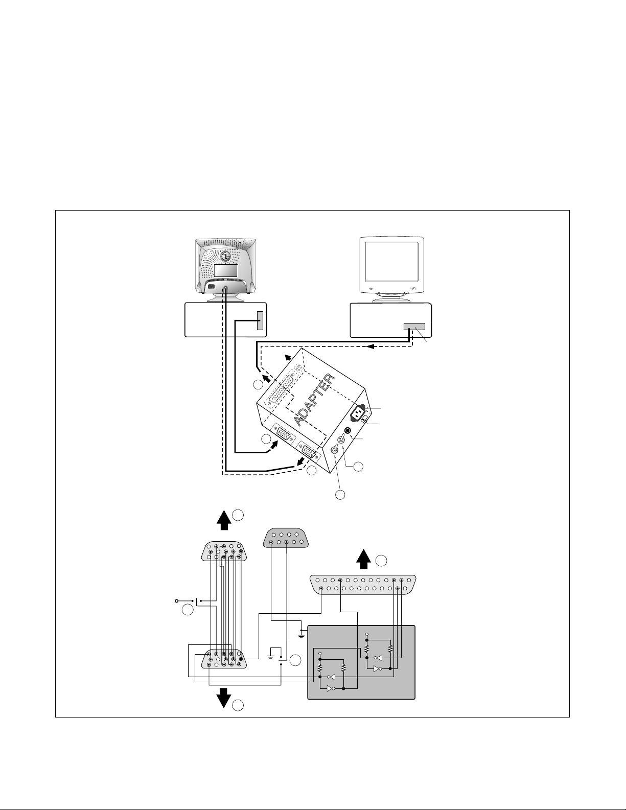
Figure 1. Cable Connection
13)
Adjust R-DRIVE and B-DRIVE command to white
balance x=0.281
±
0.002 and y=0.311±0.002 on the
White Balance Meter with PC arrow keys.
14)
Adjust SUB-CONTRAST command to 55±0.5FL of
the color 15,0 box pattern (70x70mm) luminance at
mode 3 and save in color 1.
15)
Display color 15,0 full white patten at Mode 3.
16)
COLOR ADJ. → LUMINANCE → ABL command.
17)
Adjust ABL to 40±0.5FL of the luminance.
18)
Exit from the program.
5. Adjustment for Focus.
1) Display H character in full screen at Mode 4.
2) Adjust Focus control on the FBT that focus should be
the best condition.
220
Monitor to be
adjusted
Video
Signal
Generator
IBM
Compatible PC
Parallel Port
Power inlet (required)
Power LED
ST Switch
Power Select Switch
(110V/220V)
Control Line
Not used
RS232C
PARALLEL
V-SYNC
POWER
ST
VGS
MONITOR
E
E
V-Sync On/Off Switch
(Switch must be ON.)
F
F
A
A
B
B
C
C
15
10
5
5
69
1
1
1
14
13
25
6
5V
5V
5V
4.7K
4.7K
4.7K
74LS06
74LS06
OFF ON
OFF
ON
11
 Loading...