

LG LH-C6230P, LH-C6230LGEDG, LH-C6230LGEES, LH-C6230LGEPT, LH-C6230LGEIS Service Manual
...Page 1

SERVICE MANUAL MODELS : LH-C6230P/C6231P/LH-C6230S/LH-C6230W/LH-C6231W/LH-C6230X/LH-C6230Y/C6231Y
DVD/CD/VCR RECEIVER
Home Cinema System
SERVICE MANUAL
P/N : 3829RDT033C JULY, 2003
MODELS: LH-C6230P/C6231P (LGEDG/LGEES/LGEPT/LGEIS)
LH-C6230S (LGEFS/STUH) LH-C6230W (LGESA/LGEGF)
LH-C6231W (LGEAP) LH-C6230X (MOSCOW)
LH-C6230Y/C6231Y (LGEPL/LGEMK)
Page 2

- 1-1 -
SECTION 1. GENERAL
• PRODUCT SAFETY SERVICING GUIDELINES FOR VIDEO PRECAUTIONS
........................
1-2
• SERVICING PRECAUTIONS........................................................................................................ 1-5
• ESD PRECAUTIONS
...................................................................................................................
1-6
• SPECIFICATIONS
.......................................................................................................................
1-7
SECTION 2. AUDIO PART
• AMP ELECTRICAL TROUBLESHOOTING GUDIE
.....................................................................
2-1
• BLOCK DIAGRAM......................................................................................................................... 2-2
• AUDIO SCHEMATIC DIAGRAMS
...............................................................................................
2-4
• WIRING DIAGRAM
....................................................................................................................
2-10
• AUDIO VOLTAGE SHEET (IC&TR) ............................................................................................ 2-12
• PRINTED CIRCUIT DIAGRAM ................................................................................................... 2-14
SECTION 3. VCR PART
• ELECTRICAL ADJUSTMENT PROCEDURES
............................................................................
3-1
• VCR ELECTRICAL TROUBLESHOOTING
...................................................................................
3-2
• VCR SHEMATIC DIAGRAMS ..................................................................................................... 3-17
• VCR VOLTAGE SHEET (IC&TR)................................................................................................ 3-29
• PRINTED CIRCUIT DIAGRAMS ................................................................................................. 3-31
SECTION 4. MECHANSIM OF VCR PART
.......................................................................
4-1
SECTION 5. DVD PART
• DVD ELECTRICAL TROUBLESHOOTING................................................................................... 5-1
• DETAILS AND WAVEFORMS ON SYSTEM TEST AND DEBUGGING ...................................... 5-7
• DVD PART SCHEMATIC DIAGRAMS ........................................................................................ 5-21
• VOLTAGE SHEET (IC&TR) ........................................................................................................ 5-29
• PRINTED CIRCUIT DIAGRAM ................................................................................................... 5-31
SECTION 6. MECHANSIM OF DVD PART
.......................................................................
6-1
SECTION 7. EXPLODED VIEWS PART
...........................................................................
7-1
• Cabinet and Main frame ................................................................................................................ 7-1
• Speaker ........................................................................................................................................ 7-3
SECTION 8. REPLACEMENT PARTS LIST
.....................................................................
8-1
CONTENTS
Page 3
- 1-2 -
SECTION 1. GENERAL PART
CAUTION : DO NOT ATTEMPT TO MODIFY THIS PRODUCT IN ANY WAY,
NEVER PERFORM CUSTOMIZED INSTALLATIONS WITHOUT MANUFACTURER S APPROVAL. UNAUTHORIZED MODIFICATIONS WILL NOT ONLY
VOID THE WARRANTY, BUT MAY LEAD TO YOUR BEING LIABLE FOR ANY
RESULTING PROPERTY DAMAGE OR USER INJURY.
SERVICE WORK SHOULD BE PERFORMED ONLY AFTER YOU ARE
THOROUGHLY FAMILIAR WITH ALL OF THE FOLLOWING SAFETY
CHECKS AND SERVICING GUIDELINES. TO DO OTHERWISE,
INCREASES THE RISK OF POTENTIAL HAZARDS AND INJURY TO THE
USER.
WHILE SERVICING, USE AN ISOLATION TRANSFORMER FOR PROTECTION FROM A.C. LINE SHOCK.
SAFETY CHECKS
AFTER THE ORIGINAL SERVICE PROBLEM HAS BEEN CORRCTED. A
CHECK SHOULD BE MADE OF THE FOLLOWING.
SUBJECT : FIRE & SHOCK HAZARD
1. BE SURE THAT ALL COMPONENTS ARE POSITIONED IN SUCH A WAY
AS TO AVOID POSSIBILITY OF ADJACENT COMPONENT SHORTS.
THIS IS ESPECIALLY IMPORTANT ON THOSE MODULES WHICH ARE
TRANSPORTED TO AND FROM THE REPAIR SHOP.
2. NEVER RELEASE A REPAIR UNLESS ALL PROTECTIVE DEVICES
SUCH AS INSULATORS, BARRIERS, COVERS, SHIELDS, STRAIN
RELIEFS, POWER SUPPLY CORDS, AND OTHER HARDWARE HAVE
BEEN REINSTALLED PER ORIGINAL DESIGN. BE SURE THAT THE
SAFETY PURPOSE OF THE POLARIZED LINE PLUG HAS NOT BEEN
DEFEATED.
3. SOLDERING MUST BE INSPECTED TO DISCOVER POSSIBLE COLD
SOLDER JOINTS, SOLDER SPLASHES OR SHARP SOLDER POINTS.
BE CERTAIN TO REMOVE ALL LOOSE FOREIGN PARTICLES.
4. CHECK FOR PHYSICAL EVIDENCE OF DAMAGE OR DETERIORATION
TO PARTS AND COMPONENTS. FOR FRAYED LEADS, DAMAGED
INSULATION (INCLUDING A.C. CORD). AND REPLACE IF NECESSARY
FOLLOW ORIGINAL LAYOUT, LEAD LENGTH AND DRESS.
5. NO LEAD OR COMPONENT SHOULD TOUCH A RECIVING TUBE OR
A RESISTOR RATED AT 1 WATT OR MORE. LEAD TENSION AROUND
PROTRUNING METAL SURFACES MUST BE AVOIDED.
6. ALL CRITICAL COMPONENTS SUCH AS FUSES, FLAMEPROOF
RESISTORS, CAPACITORS, ETC. MUST BE REPLACED WITH EXACT
FACTORY TYPES, DO NOT USE REPLACEMENT COMPONENTS
OTHER THAN THOSE SPECIFIED OR MAKE UNRECOMMENDED CIRCUIT MODIFICATIONS.
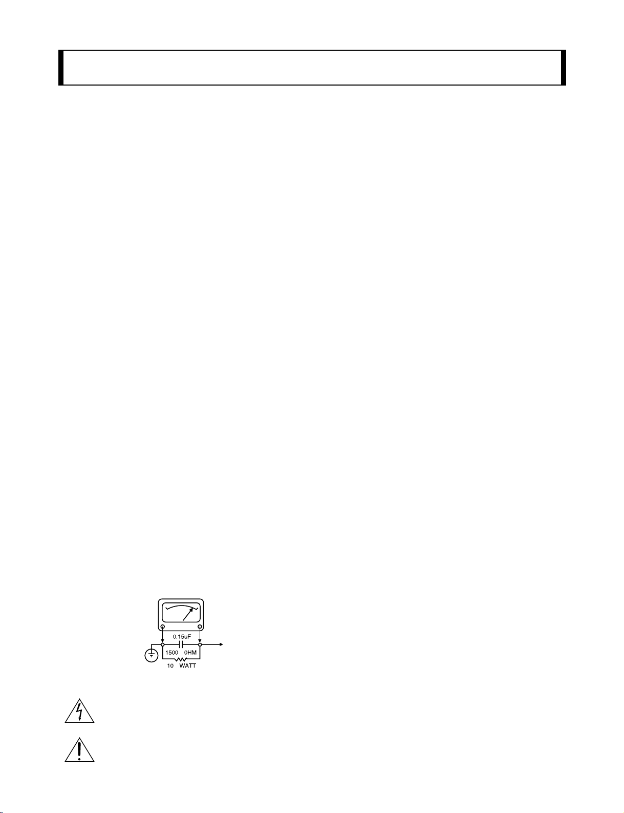
7. AFTER RE-ASSEMBLY OF THE SET ALWAYS PERFORM AN A.C.
LEAKAGE TEST ON ALL EXPOSED METALLIC PARTS OF THE CABINET, (THE CHANNEL SELECTOR KNOB, ANTENNA TERMINALS. HANDLE AND SCREWS) TO BE SURE THE SET IS SAFE TO OPERATE
WITHOUT DANGER OF ELECTRICAL SHOCK. DO NOT USE A LINE
ISOLATION TRANSFORMER DURING THIS TEST USE AN A.C. VOLTMETER, HAVING 5000 OHMS PER VOLT OR MORE SENSITIVITY, IN
THE FOLLOWING MANNER; CONNECT A 1500 OHM 10 WATT RESISTOR, PARALLELED BY A .15 MFD. 150.V A.C TYPE CAPACITOR
BETWEEN A KNOWN GOOD EARTH GROUND (WATER PIPE, CONDUIT, ETC.) AND THE EXPOSED METALLIC PARTS, ONE AT A TIME.
MEASURE THE A.C. VOLTAGE ACROSS THE COMBINATION OF 1500
OHM RESISTOR AND .15 MFD CAPACITOR. REVERSE THE A.C. PLUG
AND REPEAT A.C. VOLTAGE MEASUREMENTS FOR EACH EXPOSED
METALLIC PART. VOLTAGE MEASURED MUST NOT EXCEED 75
VOLTS R.M.S. THIS CORRESPONDS TO 0.5 MILLIAMP A.C ANY
VALUE EXCEEDING THIS LIMIT CONSTITUTES A POTENTIAL SHOCK
HAZARD AND MUST BE CORRECTED IMMEDIATELY.
SUBJECT: GRAPHIC SYMBOLS
THE LIGHTNING FLASH WITH APROWHEAD SYMBOL. WITHIN
AN EQUILATERAL TRIANGLE, IS INTENDED TO ALERT THE
SERVICE PERSONNEL TO THE PRESENCE OF UNINSULATED
DANGEROUS VOLTAGE THAT MAY BE OF SUFFICIENT MAG-
NITUDE TO CONSTITUTE A RISK OF ELECTRIC SHOCK.
THE EXCLAMATION POINT WITHIN AN EQUILATERAL TRIAN-
GLE IS INTENDED TO ALERT THE SERVICE PERSONNEL TO
THE PRESENCE OF IMPORTANT SAFETY INFORMATION IN
SERVICE LITERATURE.
SUBJECT : X-RADIATION
1. BE SURE PROCEDURES AND INSTRUCTIONS TO ALL SERVICE PERSONNEL COVER THE SUBJECT OF X-RADIATION. THE ONLY POTENTIAL SOURCE OF X-RAYS IN CURRENT T.V. RECEIVERS IS THE PICTURE TUBE. HOWEVER, THIS TUBE DOES NOT EMIT X-RAYS WHEN
THE HIGH VOLTAGE IS AT THE FACTORY SPECIFIED LEVEL. THE
PROPER VALUE IS GIVEN IN THE APPLICABLE SCHEMATIC. OPERATION AT HIGHER VOLTAGES MAY CAUSE A FAILURE OF THE PICTURE TUBE OR HIGH VOLTAGE SUPPLY AND, UNDER CERTAIN CIRCUMSTANCES, MAY PRODUCE RADIATION IN EXCESS OF DESIRABLE LEVELS.
2. ONLY FACTORY SPECIFIED C.R.T. ANODE CONNECTORS MUST BE
USED. DEGAUSSING SHIELDS ALSO SERVE AS X-RAY SHIELD IN
COLOR SETS, ALWAYS RE-INSTALL THEM.
3. IT IS ESSNTIAL THAT SERVICE PERSONNEL HAVE AVAILABLE AN
ACCURATE AND RELIABLE HIGH VOLTAGE METER. THE CALIBRA
TION OF THE METER SHOULD BE CHECKED PERIODICALLY
AGAINST A REFERENCE STANDARD, SUCH AS THE ONE AVAILABLE
AT YOUR DISTRIBUTOR.
4. WHEN THE HIGH VOLTAGE CIRCUITRY IS OPERATING PROPERLY
THERE IS NO POSSIBILITY OF AN X-RADIATION PROBLEM. EVERY
TIME A COLOR CHASSIS IS SERVICED. THE BRIGHTNESS SHOULD
BE RUN UP AND DOWN WHILE MONITORING THE HIGH VOLTAGE
WITH A METER TO BE CERTAIN THAT THE HIGH VOLTAGE DOES
NOT EXCEED THE SPECIFIED VALUE AND THAT IT IS REGULATING
CORRECTLY, WE SUGGEST THAT YOU AND YOUR SERVICE ORGANIZATION REVIEW TEST PROCEDURES SO THAT VOLTAGE REGULATION IS ALWAYS CHECKED AS A STANDARD SERVICING PROCEDURE. AND THAT THE HIGH VOLTAGE READING BE RECORDER ON
EACH CUSTOMER S INVOICE.
5. WHEN TROUBLESHOOTING AND MAKING TEST MEASUREMENTS IN
A PRODUCT WITH A PROBLEM OF EXCESSIVE HIGH VOLTAGE,
AVOID BEING UNNECESSARILY CLOSE TO THE PICTURE TUBE AND
THE HIGH VOLTAGE SUPPLY. DO NOT OPERATE THE PRODUCT
LONGER THAN IS NECESSARY TO LOCATE THE CAUSE OF EXCES
SIVE VOLTAGE.
6. REFER TO HV. B+ AND SHUTDOWN ADJUSTMENT PROCEDURES
DESCRIBED IN THE APPROPRIATE SCHEMATIC AND DIAGRAMS
(WHERE USED).
SUBJECT: IMPLOSION
1. ALL DIRECT VIEWED PICTURE TUBES ARE EQUIPPED WITH AN INTE
GRAL IMPLOSION PROTECTION SYSTEM, BUT CARE SHOULD BE
TAKEN TO AVOID DAMAGE DURING INSTALLATION, AVOID
SCRATCHING THE TUBE. IF SCRATCHED REPLACE IT.
2. USE ONLY RECOMMENDED FACTORY REPLACEMENT TUBES.
SUBJECT : TIPS ON PROPER INSTALLATION
1. NEVER INSTALL ANY PRODUCT IN A CLOSED-IN RECESS, CUBBYHOLE OR CLOSELY FITTING SHELF SPACE. OVER OR CLOSE TO
HEAT DUCT, OR IN THE PATH OF HEATED AIR FLOW.
2. AVOID CONDITIONS OF HIGH HUMIDITY SUCH AS: OUTDOOR PATIO
INSTALLATIONS WHERE DEW IS A FACTOR, NEAR STEAM RADIATORS WHERE STEAM LEAKAGE IS A FACTOR, ETC.
3. AVOID PALCEMENT WHERE DRAPERIES MAY OBSTRUCT REAR
VENTING. THE CUSTOMER SHOULD ALSO AVOID THE USE OF DECORATIVE SCARVES OR OTHER COVERINGS WHICH MIGHT
OBSTRUCT VENTILATION.
4. WALL AND SHELF MOUNTED INSTALLATIONS USING A COMMERCIAL MOUNTING KIT. MUST FOLLOW THE FACTORY APPROVED
MOUNTING INSTRUCTIONS A PRODUCT MOUNTED TO A SHELF OR
PLATFORM MUST RETAIN ITS ORIGINAL FEET (OR THE EQUIVALENT
THICKNESS IN SPACERS) TO PROVIDE ADEQUATE AIR FLOW
ACROSS THE BOTTOM, BOLTS OR SCREWS USED FOR FASTENERS
MUST NOT TOUCH ANY PARTS OR WIRING. PERFORM LEAKAGE
TEST ON CUSTOMIZED INSTALLATIONS.
5. CAUTION CUSTOMERS AGAINST THE MOUNTING OF A PRODUCT ON
SLOPING SHELF OR A TILTED POSITION, UNLESS THE PRODUCT IS
PROPERLY SECURED.
6. A PRODUCT ON A ROLL-ABOUT CART SHOULD BE STABLE ON ITS
MOUNTING TO THE CART. CAUTION THE CUSTOMER ON THE HAZARDS OF TRYING TO ROLL A CART WITH SMALL CASTERS ACROSS
THRESHOLDS OR DEEP PILE CARPETS.
7. CAUTION CUSTOMERS AGAINST THE USE OF A CART OR STAND
WHICH HAS NOT BEEN LISTED BY UNDERWRITERS LABORATORIES,
INC. FOR USE WITH THEIR SPECIFIC MODEL OF TELEVISION
RECEIVER OR GENERICALLY APPROVED FOR USE WITH T.V. S OF
THE SAME OR LARGER SCREEN SIZE.
8. CAUTION CUSTOMERS AGAINST THE USE OF EXTENSION CORDS,
EXPLAIN THAT A FOREST OF EXTENSIONS SPROUTING FROM A SINGLE OUTLET CAN LEAD TO DISASTROUS CONSEQUENCES TO
HOME AND FAMILY.
PRODUCT SAFETY SERVICING GUIDELINES FOR VIDEO PRODUCTS
A.C. VOLTMETER
GOOD EARTH GROUND
SUCH AS THE WATER
PIPE. CONDUIT. ETC
PLACE THIS PROBE
ON EACH EXPOSED
METAL PART
Page 4
NOTES REGARDING HANDLING OF THE PICK-UP
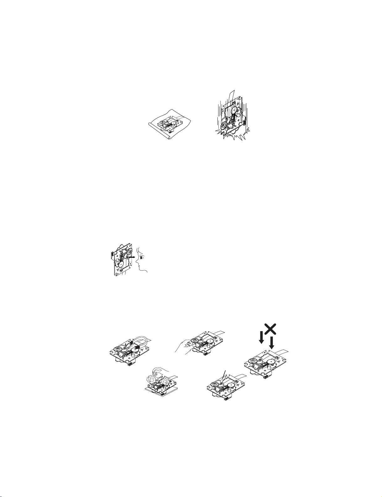
1. Notes for transport and storage
1) The pick-up should always be left in its conductive bag until immediately prior to use.
2) The pick-up should never be subjected to external pressure or impact.
2. Repair notes
1) The pick-up incorporates a strong magnet, and so should never be brought close to magnetic materials.
2) The pick-up should always be handled correctly and carefully, taking care to avoid external pressure and
impact. If it is subjected to strong pressure or impact, the result may be an operational malfunction and/or
damage to the printed-circuit board.
3) Each and every pick-up is already individually adjusted to a high degree of precision, and for that reason
the adjustment point and installation screws should absolutely never be touched.
4) Laser beams may damage the eyes!
Absolutely never permit laser beams to enter the eyes!
Also NEVER switch ON the power to the laser output part (lens, etc.) of the pick-up if it is damaged.
5) Cleaning the lens surface
If there is dust on the lens surface, the dust should be cleaned away by using an air bush (such as used
for camera lens). The lens is held by a delicate spring. When cleaning the lens surface, therefore, a
cotton swab should be used, taking care not to distort this.
6) Never attempt to disassemble the pick-up.
Spring by excess pressure. If the lens is extremely dirty, apply isopropyl alcohol to the cotton swab. (Do
not use any other liquid cleaners, because they will damage the lens.) Take care not to use too much of
this alcohol on the swab, and do not allow the alcohol to get inside the pick-up.
- 1-3 -
Storage in conductive bag
Drop impact
NEVER look directly at the laser beam, and don’t let
contact fingers or other exposed skin.
Magnet
How to hold the pick-up
Pressure
Pressure
Cotton swab
Conductive Sheet
Page 5
- 1-4 -
NOTES REGARDING COMPACT DISC PLAYER REPAIRS
1. Preparations
1) Compact disc players incorporate a great many ICs as well as the pick-up (laser diode). These
components are sensitive to, and easily affected by, static electricity. If such static electricity is high
voltage, components can be damaged, and for that reason components should be handled with care.
2) The pick-up is composed of many optical components and other high-precision components. Care must
be taken, therefore, to avoid repair or storage where the temperature of humidity is high, where strong
magnetism is present, or where there is excessive dust.
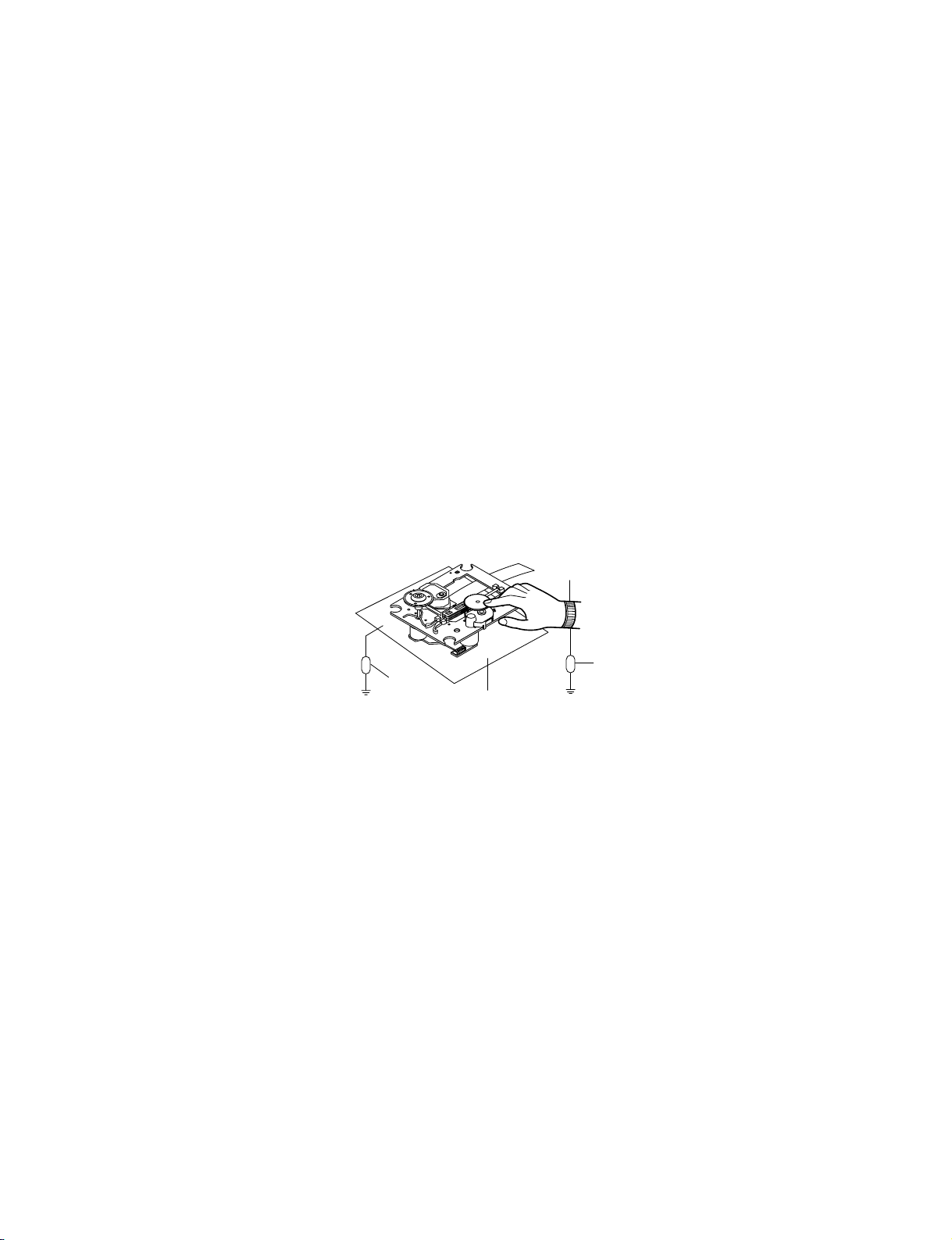
2. Notes for repair
1) Before replacing a component part, first disconnect the power supply lead wire from the unit
2) All equipment, measuring instruments and tools must be grounded.
3) The workbench should be covered with a conductive sheet and grounded.
When removing the laser pick-up from its conductive bag, do not place the pick-up on the bag. (This is
because there is the possibility of damage by static electricity.)
4) To prevent AC leakage, the metal part of the soldering iron should be grounded.
5) Workers should be grounded by an armband (1MΩ)
6) Care should be taken not to permit the laser pick-up to come in contact with clothing, in order to prevent
static electricity changes in the clothing to escape from the armband.
7) The laser beam from the pick-up should NEVER be directly facing the eyes or bare skin.
Armband
Conductive
Sheet
Resistor
(1 Mohm)
Resistor
(1 Mohm)
Page 6

- 1-5 -
SERVICING PRECAUTIONS
CAUTION : Before servicing the COMBI HOME THEATER
SYSTEM covered by this service data and its supplements
and addends, read and follow the
SAFETY PRECAUTIONS.
NOTE
: if unforeseen circumstances create conflict between
the following servicing precautions and any of the safety precautions in this publications, always follow the safety precautions.
Remembers Safety First:
General Servicing Precautions
1. Always unplug the COMBI HOME THEATER SYSTEM AC
power cord from the AC power source before:
(1) Removing or reinstalling any component, circuit board,
module, or any other assembly.
(2) Disconnection or reconnecting any internal electrical
plug or other electrical connection.
(3) Connecting a test substitute in parallel with an elec-
trolytic capacitor.
Caution : A wrong part substitution or incorrect
polarity installation of electrolytic capacitors may result
in an explosion hazard.
2. Do not spray chemicals on or near this COMBI HOME
THEATER SYSTEM or any of its assemblies.
3. Unless specified otherwise in this service data, clean
electrical contacts by applying an appropriate contact
cleaning solution to the contacts with a pipe cleaner,
cotton-tipped swab, or comparable soft applicator.
Unless specified otherwise in this service data, lubrication
of contacts is not required.
4. Do not defeat any plug/socket B+ voltage interlocks with
whitch instruments covered by this service manual might
be equipped.
5. Do not apply AC power to this COMBI HOME THEATER
SYSTEM and/or any of its electrical assemblies unless all
solid-state device heat sinks are cerrectly installed.
6. Always connect test instrument ground lead to the
appropriate ground before connection the test instrument
positive lead. Always remove the test instrument ground
lead last.
Insulation Checking Procedure
Disconnect the attachment plug from the AC outlet and turn
the power on. Connect an insulation resistance meter(500V)
to the blades of the attachment plug. The insulation resistance between each blade of the attachment plug and accessible conductive parts (Note 1) should be more than 1Mohm.
Note 1 : Accessible Conductive Parts including Metal panels, Input terminals, Earphone jacks, etc.
Electrostatically Sensitive (ES) Devices
Some semiconductor (solid state) devices can be damaged
easily by static electricity. Such components commonly are
called Electrostatically Sensitive (ES) Devices. Examples of
typical ES devices are integrated circuits and some field
effect transistors and semiconductor chip components.
The following techniques should be used to help reduce the
incidence of component damage caused by static electricity.
1. Immediately before handling any semiconductor component or semiconductor-equipped assembly, drain off any
electrostatic charge on your body by touching a known
earth ground. Alternatively, obtain and wear a commercially available discharging wrist strap device, which
should be removed for potential shock reasons prior to
applying power to the unit under test.
2. After removing an electrical assembly equipped with ES
devices, place the assembly on a conductive surface such
as aluminum foil, to prevent electrostatic charge buildup or
exposure of the assembly.
3. Use only a grouned-tip soldering iron to solder or unsolder
ES devices.
4. Use only an anti-static solder removal device. Some
solder removal devices not classified a anti-static can
generate electrical charges sufficient to damage ES
devices.
5. Do not use freon-propelled chemicals. These can
generate electrical charge sufficient to damage ES
devices.
6. Do not remove a replacement ES device from its protec
tive package until immediately before you are ready to
install it. (Most replacement ES devices are packaged with
leads electrically shorted together by conductive foam,
aluminum foil, or comparable conductive material).
7. Immediately before removing the protective material from
the leads of a replacement ES device, touch the protective
material to the chassis or circuit assembly into which the
device will be installed.
Caution : Be sure no power is applied to the chassis or
circuit, and observe all other safety precautions.
8. Minimize bodily motions when handling unpackaged
replacement ES devices. (Normally harmless motion such
as the brushing together of your clothes fabric or the lifting
of your foot from a carpeted floor can generate static electricity sufficient to damage an ES device.)
Page 7
- 1-6 -
ESD PRECAUTIONS
Electrostatically Sensitive Devices (ESD)
Some semiconductor (solid state) devices can be damaged easily by static electricity. Such components
commonly are called Electrostatically Sensitive Devices (ESD). Examples of typical ESD devices are integrated
circuits and some field-effect transistors and semiconductor chip components. The following techniques should
be used to help reduce the incidence of component damage caused by static electricity.
1. Immediately before handling any semiconductor component or semiconductor-equipped assembly, drain off
any electrostatic charge on your body by touching a known earth ground. Alternatively, obtain and wear a
commercially available discharging wrist strap device, which should be removed for potential shock reasons
prior to applying power to the unit under test.
2. After removing an electrical assembly equipped with ESD devices, place the assembly on a conductive
surface such as aluminum foil, to prevent electrostatic charge buildup or exposure of the assembly.
3. Use only a grounded-tip soldering iron to solder or unsolder ESD devices.
4. Use only an anti-static solder removal device. Some solder removal devices not classified as "anti-static" can
generate electrical charges sufficient to damage ESD devices.
5. Do not use freon-propelled chemicals. These can generate electrical charges sufficient to damage ESD
devices.
6. Do not remove a replacement ESD device from its protective package until immediately before you are ready
to install it. (Most replacement ESD devices are packaged with leads electrically shorted together by
conductive foam, aluminum foil or comparable conductive materials).
7. Immediately before removing the protective material from the leads of a replacement ESD device, touch the
protective material to the chassis or circuit assembly into which the device will by installed.
CAUTION : BE SURE NO POWER IS APPLIED TO THE CHASSIS OR CIRCUIT, AND OBSERVE ALL OTHER
SAFETY PRECAUTIONS.
8. Minimize bodily motions when handing unpackaged replacement ESD devices. (Otherwise harmless motion
such as the brushing together of your clothes fabric or the lifting of your foot from a carpeted floor can
generate static electricity sufficient to damage an ESD device).
CAUTION. GRAPHIC SYMBOLS
THE LIGHTNING FLASH WITH APROWHEAD SYMBOL. WITHIN AN EQUILATERAL
TRIANGLE, IS INTENDED TO ALERT THE SERVICE PERSONNEL TO THE PRESENCE OF
UNINSULATED “DANGEROUS VOLTAGE” THAT MAY BE OF SUFFICIENT MAGNITUDE TO
CONSTITUTE A RISK OF ELECTRIC SHOCK.
THE EXCLAMATION POINT WITHIN AN EQUILATERAL TRIANGLE IS INTENDED TO
ALERT THE SERVICE PERSONNEL TO THE PRESENCE OF IMPORTANT SAFETY
INFORMATION IN SERVICE LITERATURE.
Page 8

- 1-7 -
SPECIFICATIONS
General
Power requirements AC230V ~ , 50 Hz
Power consumption 130 W
Dimensions (approx.) 430 X 90 X 350 mm (w x h x d)
Mass (approx.) 8 kg (17.6 lbs)
Operating temperature 5ßC to 40ßC (41ßF to 104ßF )
Timer 24-hour display type
Operating humidity 5 % to 90 %
DVD Section
Laser Semiconductor laser, wavelength 650 nm
Signal system PAL/NTSC
Frequency response DVD (PCM 96 kHz): 8 Hz to 44 kHz
DVD (PCM 48 kHz): 8 Hz to 20 kHz
CD: 8 Hz to 20 kHz
Signal-to-noise ratio More than 65 dB (ANALOG OUT connectors only)
Harmonic distortion Less than 1.0%
Dynamic range More than 60 dB (DVD)
More than 60 dB (CD)
Outputs
S-VIDEO OUT (Y) 1.0 V (p-p), 75 ohms, negative sync, Mini DIN 4-pin x 1
(C) 0.3 V (p-p) 75 ohms
VCR Section
Head system 4 heads helical scan azimuth system
Maximum recording time SP: 4 h (E-240 tape), LP: 8 h (E-240 tape)
Rewind time About 180 min (E-180 tape)
Input level VIDEO: 1.0 V(p-p), 75 ohms, unbalanced
AUDIO: -6.0 dBm, more than 10 kohms (SCART)
-6.0 dBm, more than 47 kohms (RCA)
Output level VIDEO: 1.0 V(p-p), 75 ohms, unbalanced
Signal-to-noise ratio VIDEO: More than 43 dB
AUDIO: More than 72 dB (Hi-Fi)
More than 42 dB (Mono)
Dynamic range AUDIO: More than 85 dB
Tuner Section
Tuning range FM: 87.5 - 108.0 MHz
AM: 522 - 1611 kHz
Intermediate frequency FM: 10.7 MHz
AM: 450 kHz
Amplifier Section
Stereo mode 20W + 20W (4 ohm at 1 kHz, THD 10%)
Surround mode Front: 20W + 20W (THD 10%)
Centre: 20W
Surround: 20W + 20W (4 ohm at 1 kHz, THD 10%)
Subwoofer: 40W (8 ohm at 30 Hz, THD 10%)
Page 9

- 1-8 -
Speakers
Satellite (LHS-C6230T)
Type 1 Way 1 Speaker
Impedance 4‰
Frequency Response 130 - 20,000 Hz
Sound Pressure Level 83 dB/W (1m)
Rated Input Power 20W
Max Input Power 40W
Net Dimensions (W x H x D) 88 x 100 x 95 mm
Net Weight 0.54 kg
Passive Subwoofer (LHS-C6230W)
Type 1 Way 1 Speaker
Impedance 8‰
Frequency Response 50 - 1,500 Hz
Sound Pressure Level 82 dB/W (1m)
Rated Input Power 40W
Max Input Power 80W
Net Dimensions (W x H x D) 160 x 350 x 325 mm
Net Weight 4.12 kg
Page 10
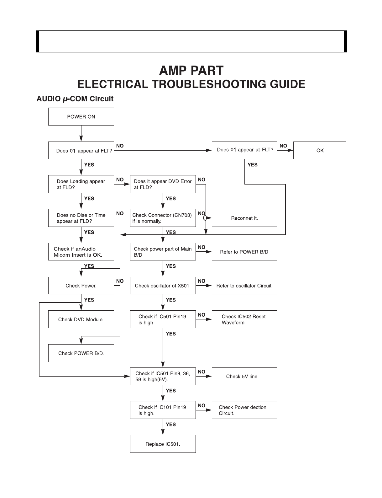
- 2-1 -
SECTION 2. AUDIO PART
Page 11
- 3-1 -
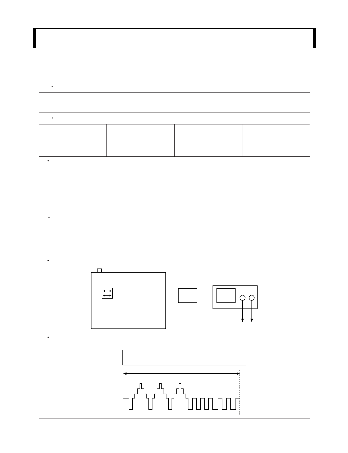
ELECTRICAL ADJUSTMENT PROCEDURES
1. Servo Adjustment
1) PG Adjustment
Test Equipment
Adjustment And Specification
a) OSCILLOSCOPE
b) NTSC MODEL : NTSC SP TEST TAPE
C) PAL MODEL : PAL SP TEST TAPE
MODE
PLAY
Adjustment Procedure
a) Insert the SP Test Tape and play.
Note - Adjust the distance of X, pressing the Tracking(+) or Tracking(-) when the ATR is blink after the
SP Test Tape is inserted.
b) Connect the CH1 of the oscilloscope to the H/SW(W373, W374) and CH2 to the Video Out for the VCR.
c) Trigger the mixed Combo Video Signal of CH2 to the CH1 H/SW(W373, W374), and then check the dis-
tance (time difference), which is from the selected A(B) Head point of the H/SW(W373, W374) signal to
the starting point of the vertical synchronized signal, to 6.5H – 0.5H (416 s, 1H=64 s).
PG Adjustment Method
a-1) Payback the SP standard tape
b-2) Press the 1 key on the Remote controller and the PLAY key on the Front Panel the same time,
then it goes in to Tracking initial mode. (Note : PAL Model 1 key on Remote controller)
c-3) Repeat the above step(No.b-2), then it finishes the PG adjusting automatically.
d-4) Stop the playback, then it goes out to PG adjusting mode after mony the PG data.
CONNECTION
WAVEFORM
V.Out
H/SW(W373, W374)
R/C TRK JIG KEY 6.5 – 0.5H
MEASUREMENT POINT ADJUSTMENT POINT SPECIFICATION
V.Out
H/SW(W373,W374)
OSCILLOSCOPE
CH1 CH2
V.out
H/SW
R/C KEY
(W373, W374)
H/SW
Composite
VIDEO
SECTION 3. VCR PART
Page 12
- 3-2 -
VCR ELECTRICAL TROULBESHOOTING
Page 13
- 3-3 -
Page 14
- 3-4 -
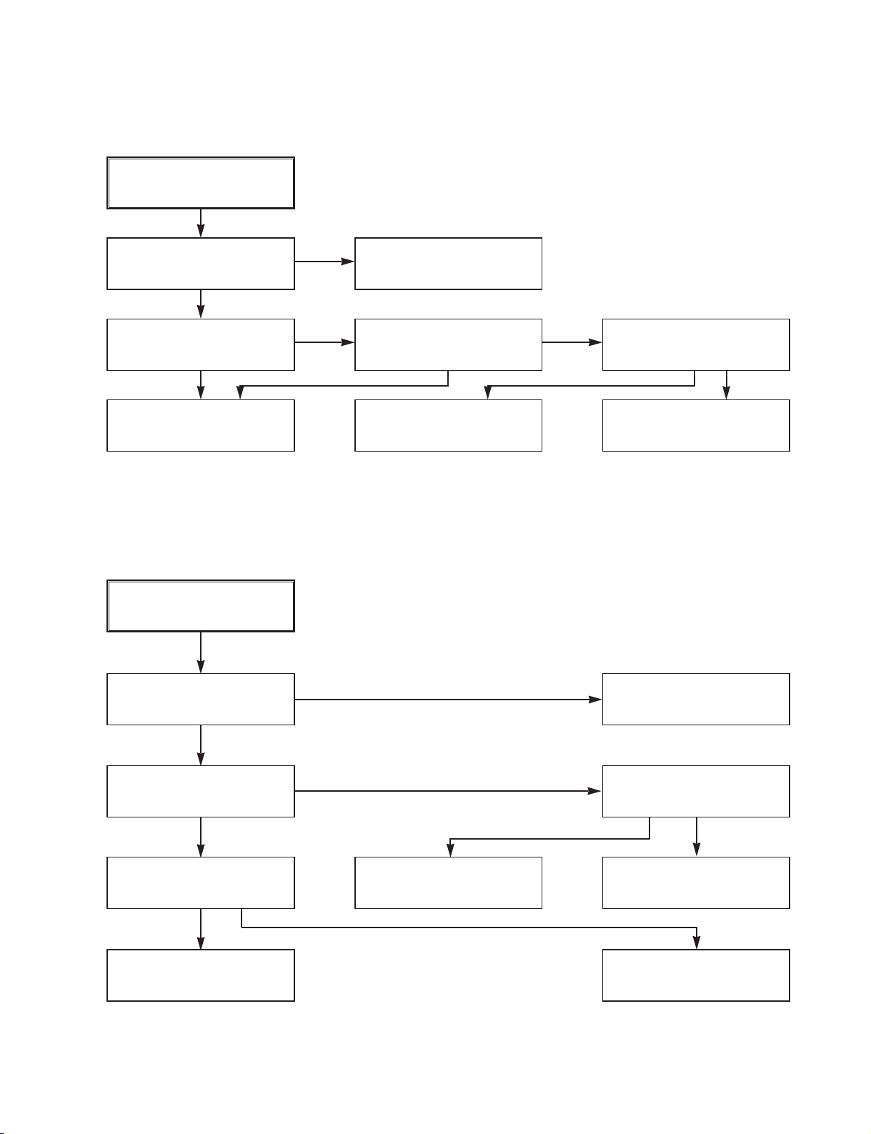
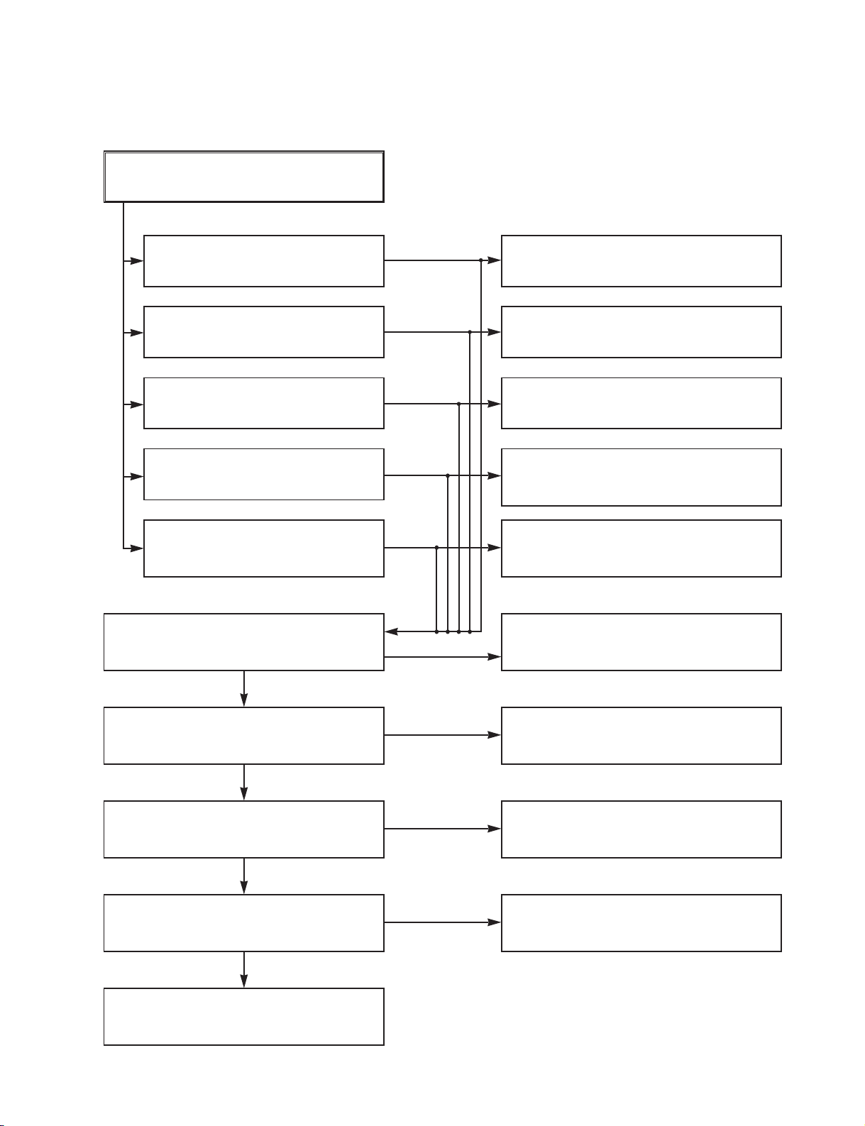
2. SYSTEM/KEY CIRCUIT
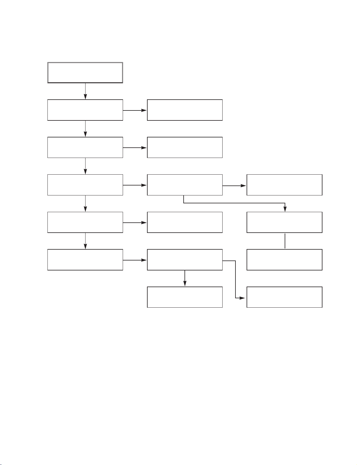
(1) AUTO STOP
(2) The unstable loading of a Cassette tape
Auto Stop
Does the SW25 waveform
appear at the IC501
Pin105?
Do the T-UP Reel Pulses
appear at the IC501 Pin49?
Is 12V applied to the
PMC01 Pin8?
Check the Drum Motor
signal.
Does 5.2V appear at the
RS501?
Check the Power Circuit.
Check the Power.
Is 5.3V applied to the
R544 ?
Refer to SMPS 5.3VA
troubleshooting.
Check the IC501
Pins68, 69, 70, 71.
Do T/UP Reel Pulses
appear at the Q514
Base terminal ?
Replace the T/UP Reel
Sensor (RS501).
Check the CST SW and
the peripheral circuitry.
Replace the IC501.
The unstable loading of a
Cassette tape
Does the H signal appear
at the IC501 Pin30 during
inserting the CST ?
Does the L signal appear
at the IC501 Pin72 during
inserting the CST?
Check the Deck
Mechanism.
Caution :
Auto stop can occur because Grease or Oil is dried up
YES
YES
YES
NO
YES
YES
YES
YES
NO
NO
NO
NO
NO
NO NO
YES
YES YES
Page 15
- 3-5 -
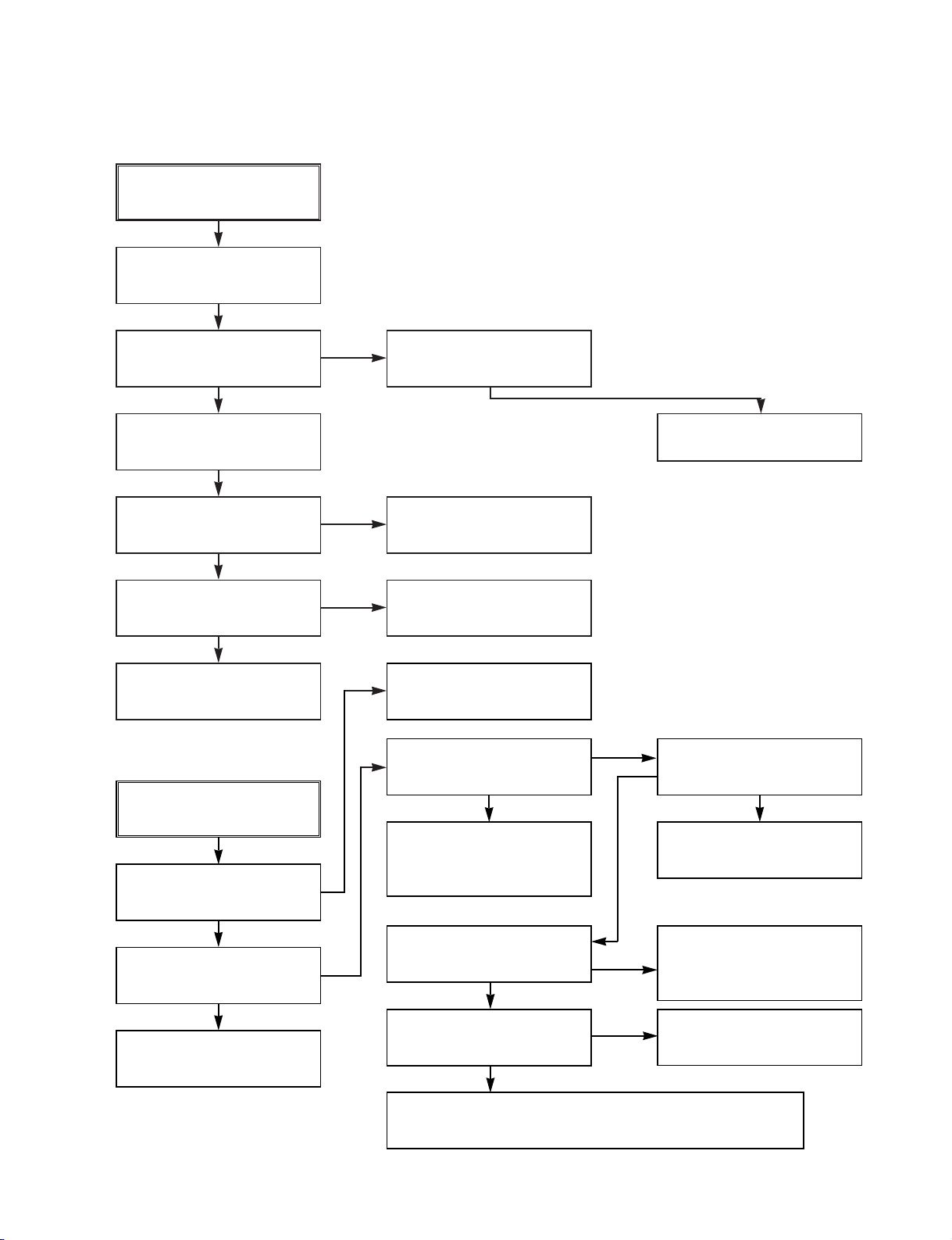
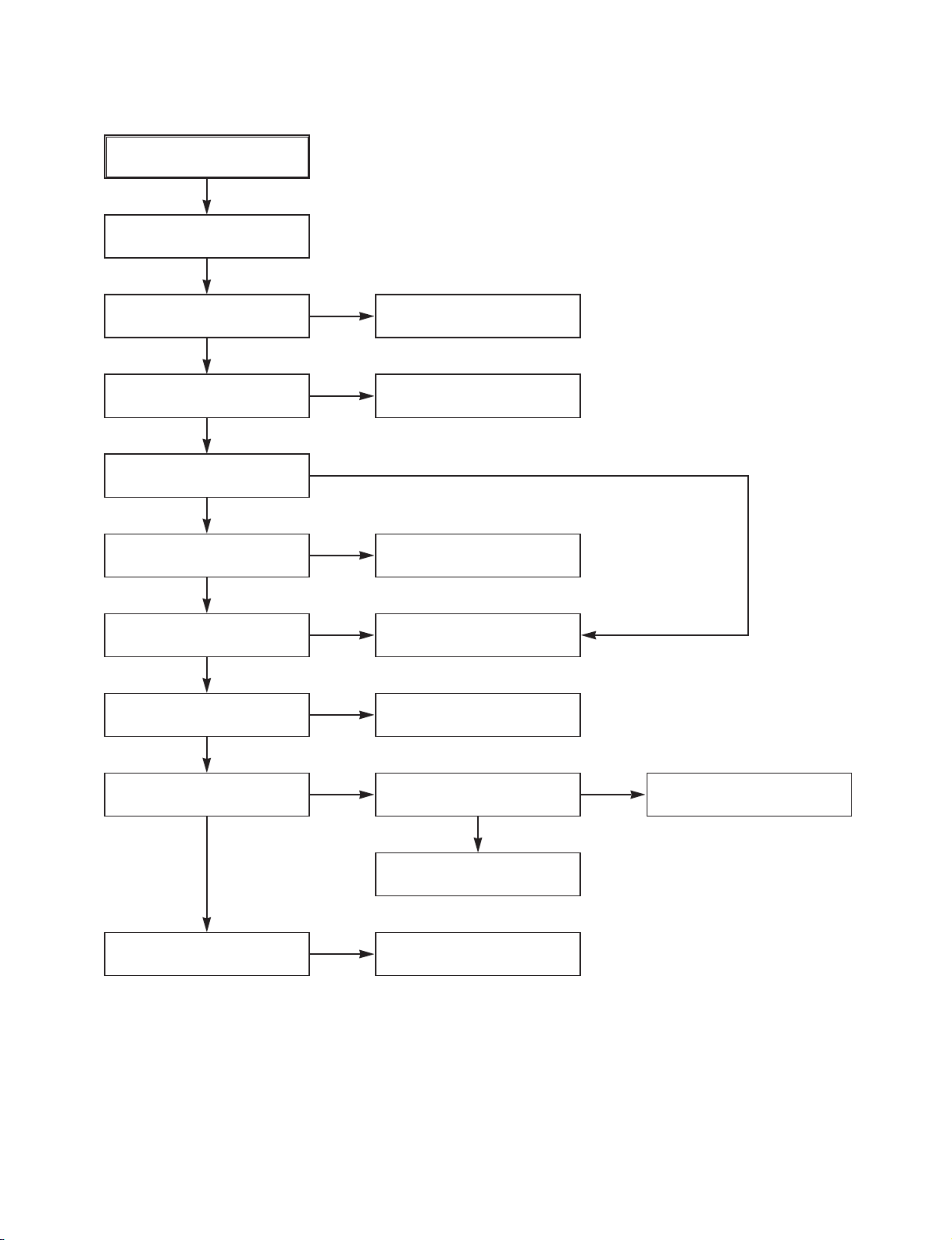
3. SERVO CIRCUIT
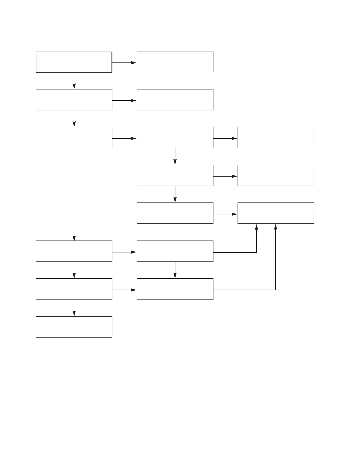
(1) Unstable Video in PB MODE
Unstable Video in
PB Mode.
Does the Noise level of the
screen change
periodically?
Do the CTL pulses appear
at the IC501 Pin8?
Is adjusting the height of
the CTL Head accurate?
Readjust the height of the
CTL Head.
Replace the IC501.
Refer to When the Y signal
doesn t appear on the
screen in PB Mode .
Does the CFG waveform
appear at the IC501
Pin9?
On tracking do the CTL
pulses move?
Does the Video Envelope
waveform appear at the
IC501 Pin24?
Replace the IC501.
YES
YES
YES
YES
YES
YES
NO
NO
NO
NO
(2) When the Drum Motor
(2) doesn t run.
Do the DFG Pulses appear
at the PMC01 Pin11?
Replace the Cap M.
Aren t the foil patterns and
the Components between
IC501 Pin104 and PMC01
Pin11 short?
Replace the IC501.
Refer to (2)
No 12VA of Power section
Do the Drum PWM Pulses
appear at the IC501
Pin107?
Aren t the foil patterns and
the Components between
IC501 Pin107 and PMC01
Pin12 short?
Do the DFG Pulses appear
at the IC501 Pin104?
Do the Drum PWM Pulses
appear at the IC501
Pin107?
Aren t the connecting patterns and the Components
between IC501 Pin107 and PMC01 Pin12 short?
When the Drum Motor
doesn t run,
Does 12V appear at the
PMC01 Pin8?
Does 2.8V appear at the
PMC01 Pin12?
Check the connector
(PMC01) and the Drum
Motor Ass y.
NO
YES
YES
YES
NO
NO
NO
NO
NO
YES
YES
YES
Page 16
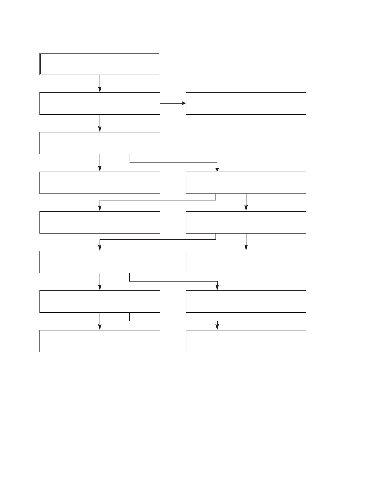
- 3-6 -
Does the CFG signal appear at the
PMC01 Pin1?
Does the PWM signal appear at the
IC501 Pin108?
Does 2.8V appear at the PMC01?
Check the PMC01 and the Capstan
Motor Ass y.
Does the Capstan PWM signal appear at
the IC501 Pin108?
Aren t the foil patterns and Components
between IC501 Pin108 and PMC01
Pin9 short?
Does the CFG signal come into the
IC501 Pin9?
Aren t the foil patterns and Components
between IC501 Pin108 and PMC01
Pin9 short?
(3) When the Capstan Motor doesn t run,
NO
NO
NO
YES
YES
YES
When the Capstan Motor doesn t run,
Does 12VA appear at the PMC01?
YES
Replace the IC501.
YES
NO
NO
YES
Refer to SMPS(CAPSTAN/12Volt)
Trouble Shooting .
Aren t the foil patterns and component
between IC501 Pin9 and PMC01
Pin1 short?
Check the Capstan Motor Ass y.
NO
Page 17
- 3-7 -
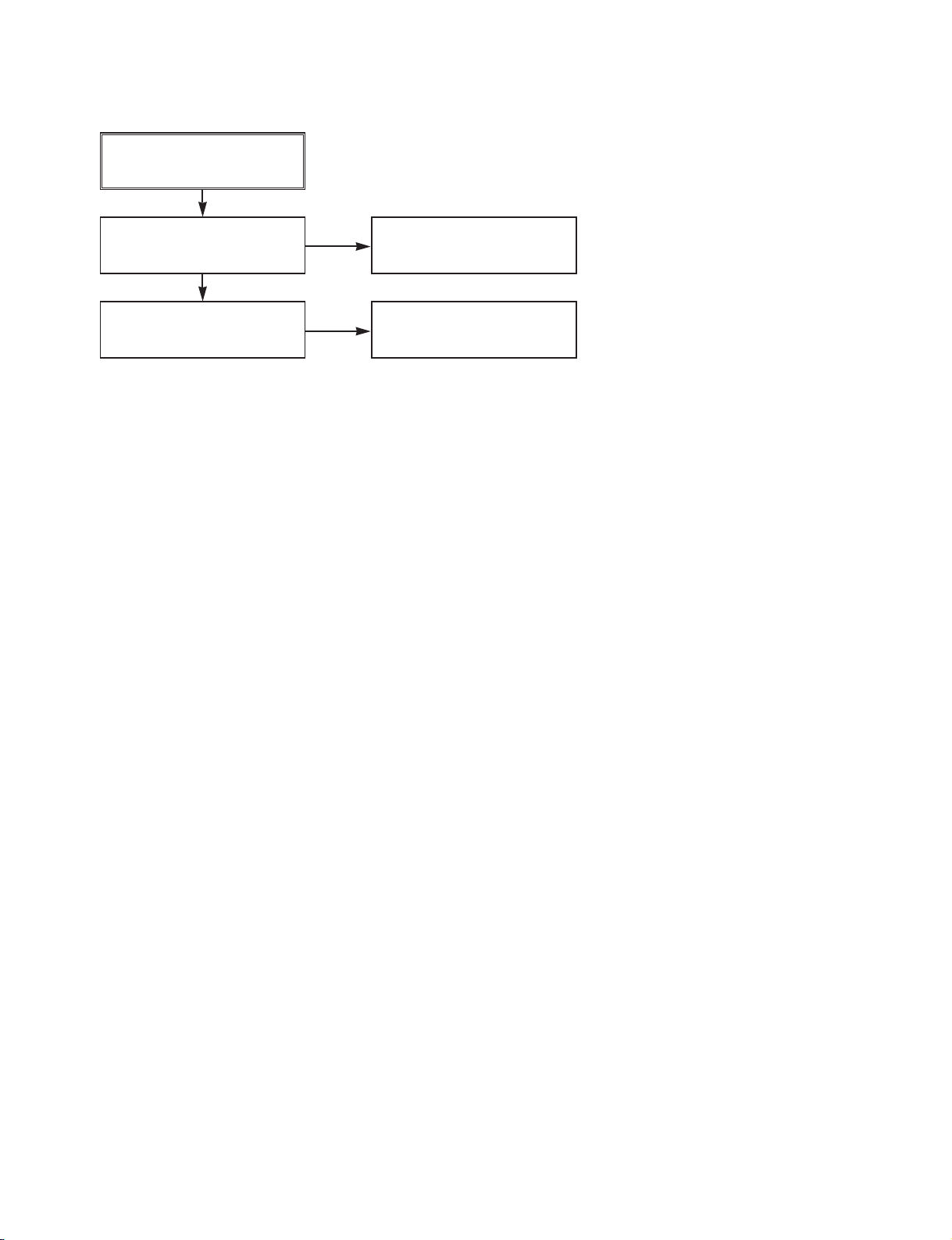
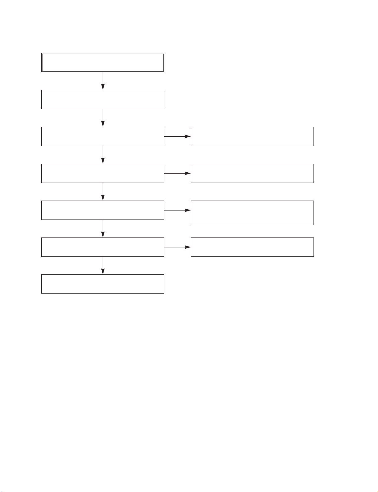
(4) KEY doesn t working
KEY doesn t working.
Is 5V applied to the IC501
Pin36?
Does LED or FLD change
when a function button is
pressed?
Refer to SMPS 5.3VA
Trouble Shooting .
Replace the defective
switches.
YES
NO
NO
Page 18
- 3-8 -
4. Y/C CIRCUIT
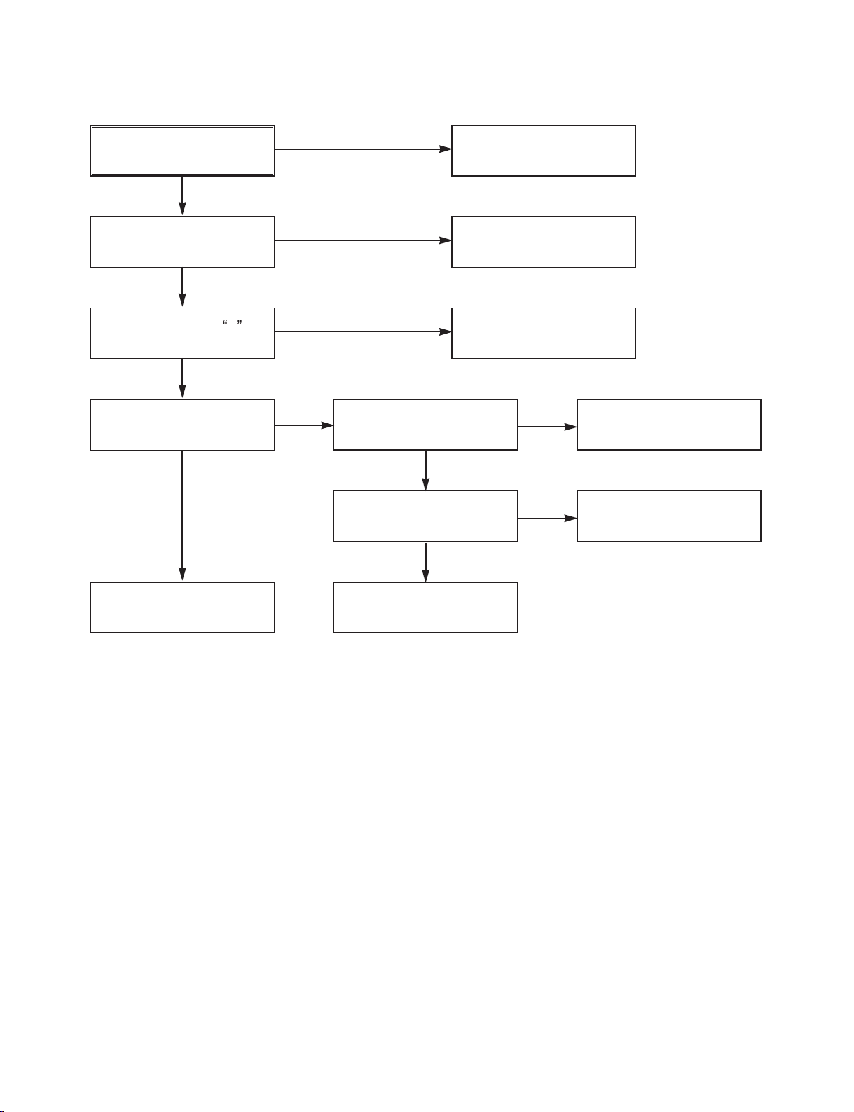
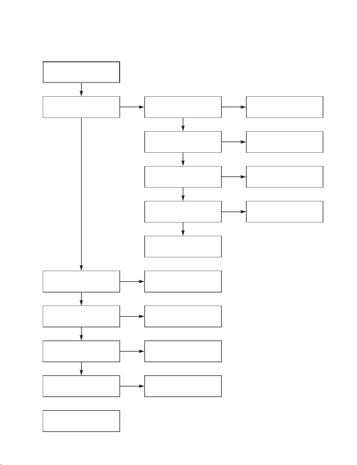
(1) No Video in EE Mode,
No Video in EE Mode
Check the 24Pin of Tuner.
Does the Video signal
appear at the IC301 Pin48?
Is 5V applied to the IC301
Pins18, 24, 42, 55, 72, 91?
Does the Video signal
appear at the IC301 Pin65?
Does the Video signal
appear at the IC501 Pin19?
Does the Video signal
appear at the Emitter terminal of the Q307, Q308?
Check the 5.2VT, 5.3VA
Line. (Power Circuit)
Is I2C BUS signal applied to
the IC301 Pins68, 69?
Check C316. (AGC)
Chck the path of the signal
between the IC301 Pin65
and IC501 Pin17.
Replace the IC301.
Does the 12VT, 5.3VA
appear at the Emitter terminal of the Q804, Q308.
Replace the Q804, Q308.
Check the 12VT, 5.3VA
Line. (Power Circuit)
Check the System Circuit.
(Refer to SYSTEM I
2
C BUS
CHECK Trouble Shooting )
YES
YES
YES
YES
YES
YES
YES
NO
NO
NO
NO
NO
NO
NO
Page 19
- 3-9 -
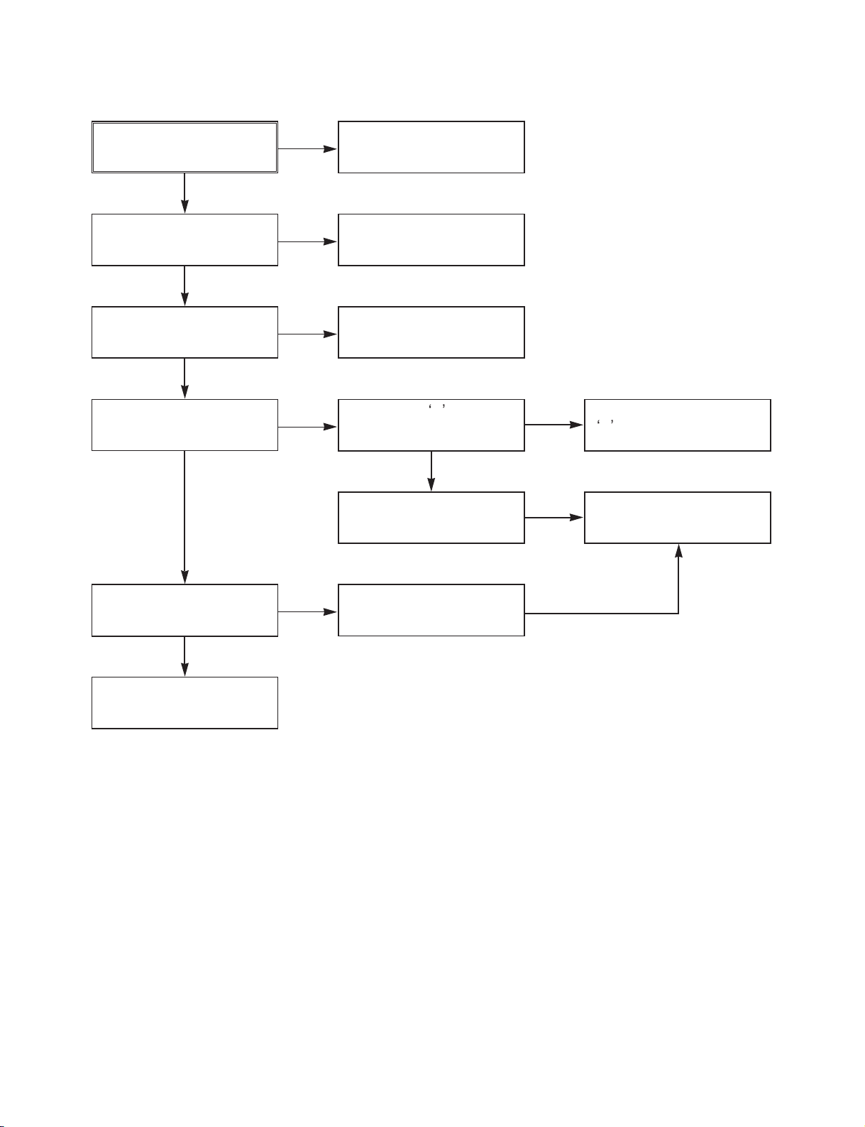
(2) When the Y(Luminance) signal doesn t appear on the screen in PB Mode,
Is 5.2VT, 5.3VA applied to the
IC301 Pins24, 42, 55, 72, 91?
Is the I2C Bus siganl applied
to the IC301 Pins68, 69 ?
Does the normal RF signal
appear at the IC301 Pin78?
Check the line of the 5.2VT,
5.3VA Line. (Power Circuit)
Check the System Circuit.
(IC501 Pin105)
Check the V.H.S/W level.
(Check R303, R304)
Replace the IC301.
Refer to SYSTEM I2C BUS
CHECK Trouble Shooting .
Is the V.H.S/W signal
applied to the IC301 Pin70?
Is V.H.S/W H about 3.4V
at the IC301 Pin70?
Clean the Drum.
Check the path of the
Y(Luminance) RF signal.
(Check C327)
Check the path of the
Y(Luminance) RF signal.
(Check the C312)
Does the Y(Luminance) RF
signal appear at the IC301
Pin76?
Is the Y(Luminance) Video
waveform showed up at
theIC301 Pin43?
Replace the IC301.
NO
NO
NO
NO
NO
NO
NO
NO
YES
YES
YES
YES
YES
YES
YES
YES
YES
Page 20
- 3-10 -
(3) When the C(Color) signal doesn t appear on the screen in PB Mode,
Is 5.2VT/5.3VA applied to the
IC301 Pins24, 42, 55, 72, 91.
Is the Color Rotary signal
applied to the IC301
Pin70?
Check the line of the 5.2VT/
5.3VA Line. (Power Circuit)
Replace the X301.
Check the Color Pass.
Check the Color Rotary
Circuit. (IC501 Pin99 )
Check the Color Rotary
level. (Check the R303)
Does the X301(4.43MHZ)
oscillate?
Replace the IC301.
Does the Color signal
appear at the IC301 Pin21?
Is Color Rotary H
about 3.4V?
Replace the IC301.
NO
NO
NO
YES
YES
YES
YES
NO
NO
NO
YES
Does the Color signal
appear at the IC301
Pin25 ?
Page 21
- 3-11 -
(4) When the Video signal doesn t appear on the screen in REC Mode,
Is the EE signal normal?
Is 5.2VT/5.3VA applied to the
IC301 Pins24,42,55,72,91?
Does the RF signal appear
at the IC301 Pin78?
Check EE Mode.
Check the System of REC
H . (the IC501 Pin47
/ the D301)
Replace the IC301.
Check the line of the 5.2VT/
5.3VA Line.(Power Circuit)
Check PB Mode.
Is the REC H signal
(about 4V) applied to the
IC301 Pin80?
Check the circuit of the
IC301 Pins85, 86.
Check REC Luminance
Pass & Color Pass.
Does PB Mdoe operate
normally?
Does the REC RF signal
appear at the IC301
Pins88,89,94,95?
Check the Drum &
Drum Connector
YES
YES
YES
YES
YES
NO
NO
NO
NO
NO
NO
YES
YES
YES
Page 22
- 3-12 -
5. Hi-Fi CIRCUIT
(A) No Sound(EE Mode)
YES
No Sound.
Check the TU Audio of IC801
Pins1, 3.
Check the DVD Audio of IC801
Pins4, 5.
Check the AV1 Audio of IC801
Pins6, 7.
Check the AV2 Audio of IC801
Pins8, 9.
Check the AV3 Audio of IC801
Pins10, 11.
Check the Vcc of IC801 Pins34, 40,
IC802 Pin4.
YES
Check the IIC Clock and DATA at
IC801 Pins42, 43, IC802 Pins32, 33.
YES
Check the Audio of IC801 Pins16, 17.
YES
Check the Audio of IC802 Pins22, 26.
YES
Check the JK801.
Check the IC751 Pins30, 31.
NO
Check the DVD MODULE.
(P8D01 Pins3, 5).
NO
Check the Scart1 Jack.
(SC901 Scart1 Audio in Pins2, 6).
NO
Check the front Jack.
(PM602 Pins3, 5).
Check the Scart2 Jack.
(SC901 Scart2 Audio in Pins2, 6).
NO
NO
Check the Power 5.2V, 12VT.
YES
NO
Check the IC501 Pins59, 60.
NO
Replace IC801.
Replace IC802.
NO
NO
Page 23
- 3-13 -
(B) Hi-Fi Playback
YES
YES
YES
YES
PB mode
No Sound.
Check the Vcc of IC801
(Pins34, 40)
Check the Hi-Fi Selection switch.
(IC801 Pin41) and the Tape quality.
Is the RF Envelope at
IC801 Pin44 over 2Vp-p?
YES
Check IC801 Pin42(Data),
Pin43(Clock)
YES
Do Audio Signals appear at
IC801 Pin16(L-CH), 17(R-CH)?
YES
Do Audio Signals appear at
IC802 Pin10(L-CH), 16(R-CH)?
YES
YES YES
Do Audio Signals appear at
IC802 Pins22, 26?
Do Audio Signals appear at
JK801?
Check Power 5.2V, 12VT.
NO
Check IC501 Pin25
(A.H/SW)
NO
NO
Check the parts of -COM
(IC501 Pins59, 60)
NO
Check the Connection at
P3D01 Pins7, 9.
NO
Check the A.IN line of
IC802(C808, C809)
NO
Check the Vcc of IC802
Pin4.
Replace IC802.
Check the Jack(JK801)
NO
NO
Check Power.
NO
Page 24
- 3-14 -
(C)
Hi-Fi REC.
It is impossible to record Hi-Fi Audio
signal.
Check Vcc of IC801.(Pins34, 40)
YES
YES
Check IC801 Pin42(Data), Pin43(CLOCK).
YES
Do Audio signals appear at IC801
Pins16, 17?
YES
Do FM Audio signals appear at IC801
Pin36?
YES
Check the Contact Point of Drum
Connector if good then Replace the Drum.
YES
Check Power 5V, 12VT.
NO
Check ports of -COM.
Check Audio input signal of IC801
Pins2, 3(TU.A.), 4, 5(DVD.A.),
6, 7(AVI.A.), 8, 9(AV2.A.), 10, 11(AV3.A.).
NO
Replace IC801.
NO
NO
Page 25
- 3-15 -
6. Tuner/IF CIRCUIT
(A) No Picture on the TV screen
No picture on the TV
screen
Does the Video signal at
the TU701 Pin24.
YES
YES
YES
Is +33V applied to TU701
Pin16?
YES
Is +5V applied to TU701
Pin13?
NO
Does Sync appear at
IC501 Pin111.
NO
Does the Video signal at
the IC501 Pin19.
YES
NO
Does the Video signal at
the IC301 Pin61.
YES
NO
NO
Does the Video signal at
the IC802 Pin30.
Check the signal flow from IC802
Pin30 to SC901 Pin19.
YES
Check 33V line.
NO
Check 5V line.
NO
YES
Does the Clock signal
appear at TU701 Pin11?
Check the lIC Clock Signal
of -COM Pin59.
NO
YES
Does the data signal
appear at TU701 Pin12?
Replace Tuner.
Check the signal flow from
TU701 Pin24 to IC301 Pin48.
Check the signal from IC301
Pin65 to IC501 Pin17.
Check the signal from IC501
Pin19 to IC301 Pin56.
Check the signal from IC501
Pin61 to IC802 Pin1.
Check the lIC Data Signal
of -COM Pin60.
NO
Page 26
- 3-16 -
(B) No Sound
No Sound.
Check the Vcc of IC751 Pins1, 11, 19,
22, 33.
YES
Check 5.2V Line.
NO
Check the Tuner SiF signal at IC751
Pin2.
YES
Check the oscillator of IC751 Pins5, 6.
YES
Check the Audio of IC751 Pins30, 31.
YES
Check the Audio of IC801 Pins2, 3.
YES
Check the Audio of IC801 Pins16, 17.
YES
Check the Audio of IC802 Pins22, 26.
YES
Check the Signal flow from IC802
Pins22, 26, SC901 Pins1, 3.
YES
Check the Tuner SIF of TU701 Pin22.
NO
Replace X751
NO
Check the IIC Clock and Data at IC751
Pins12, 13.
NO
Check the signal flow from IC751
Pins30, 31 to IC801 Pins2, 3.
NO
Check the IIC Clock and Data at IC801
Pins42, 43.
NO
Check the signal flow from IC801
Pins16, 17 to IC802 Pins10, 16.
NO
Page 27
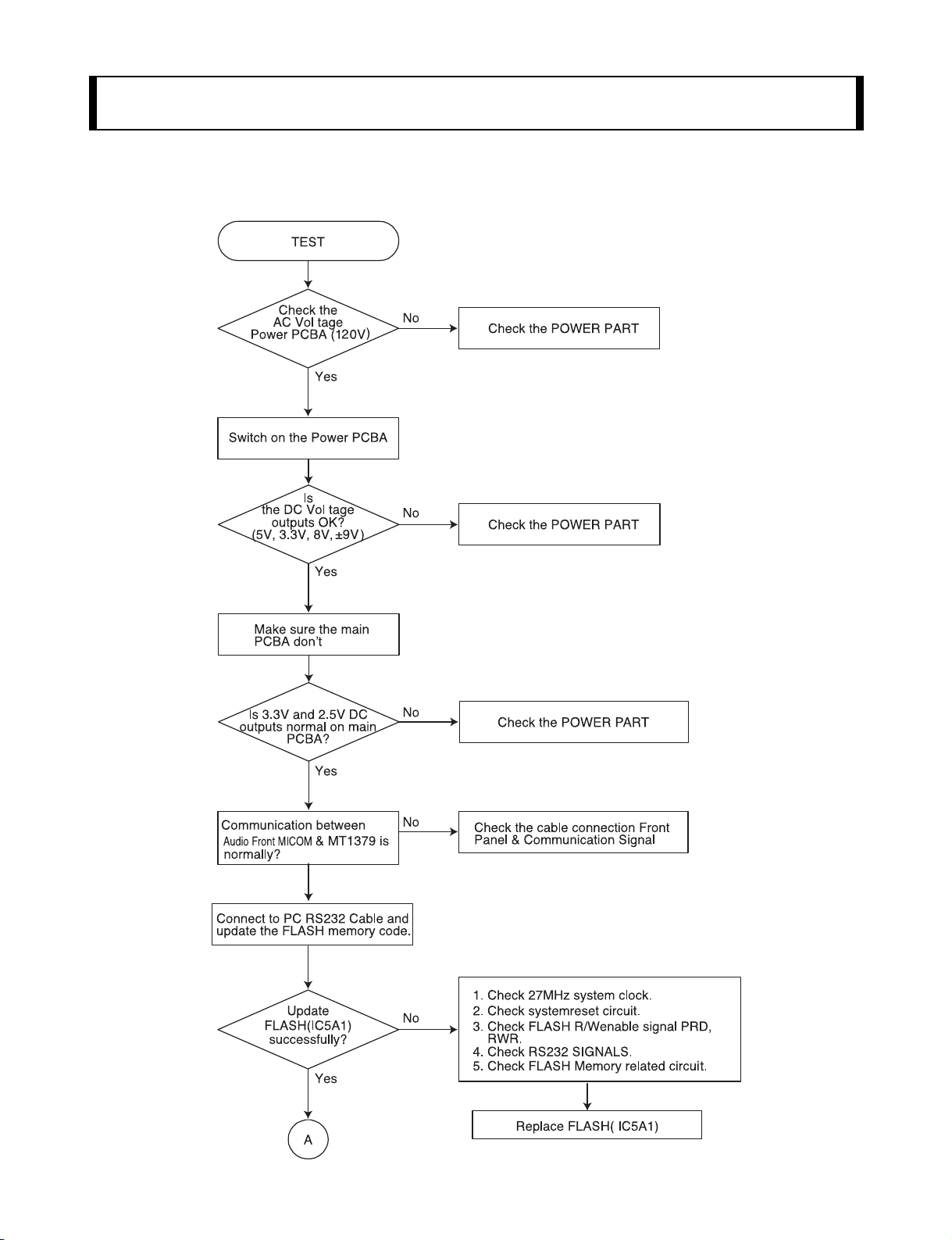
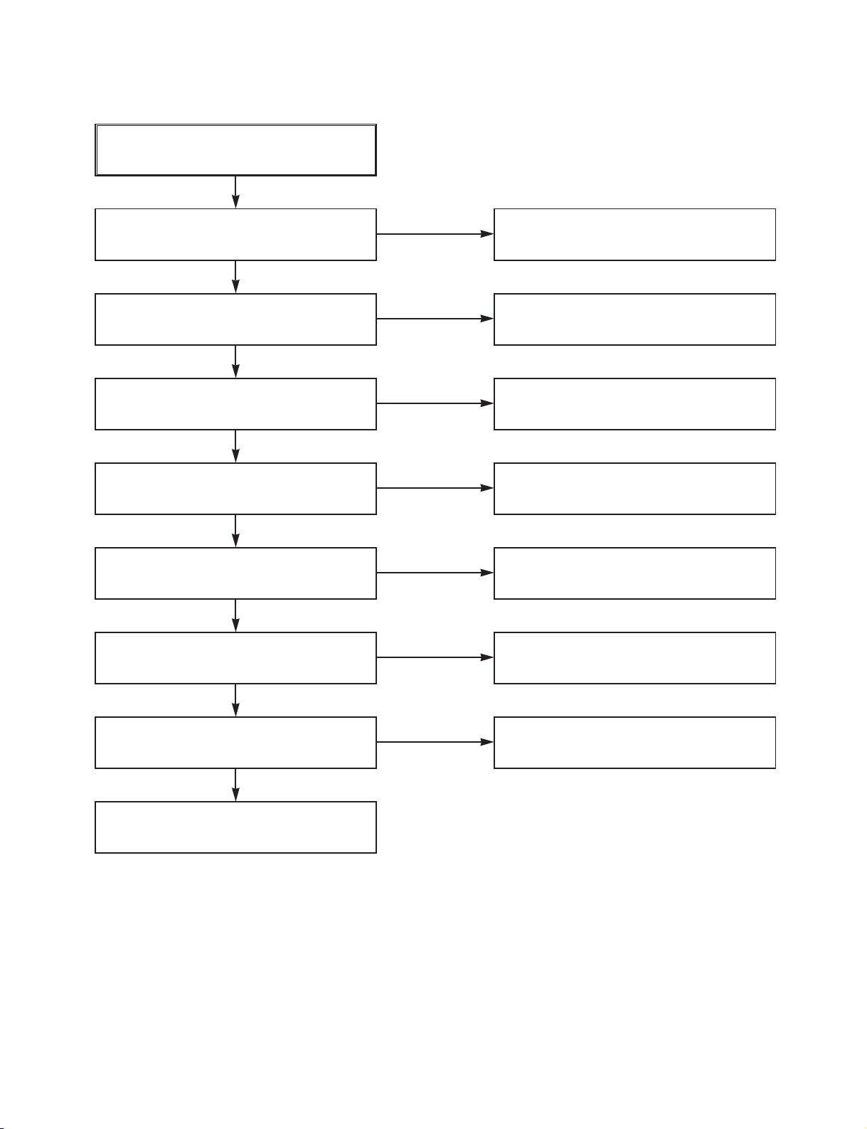
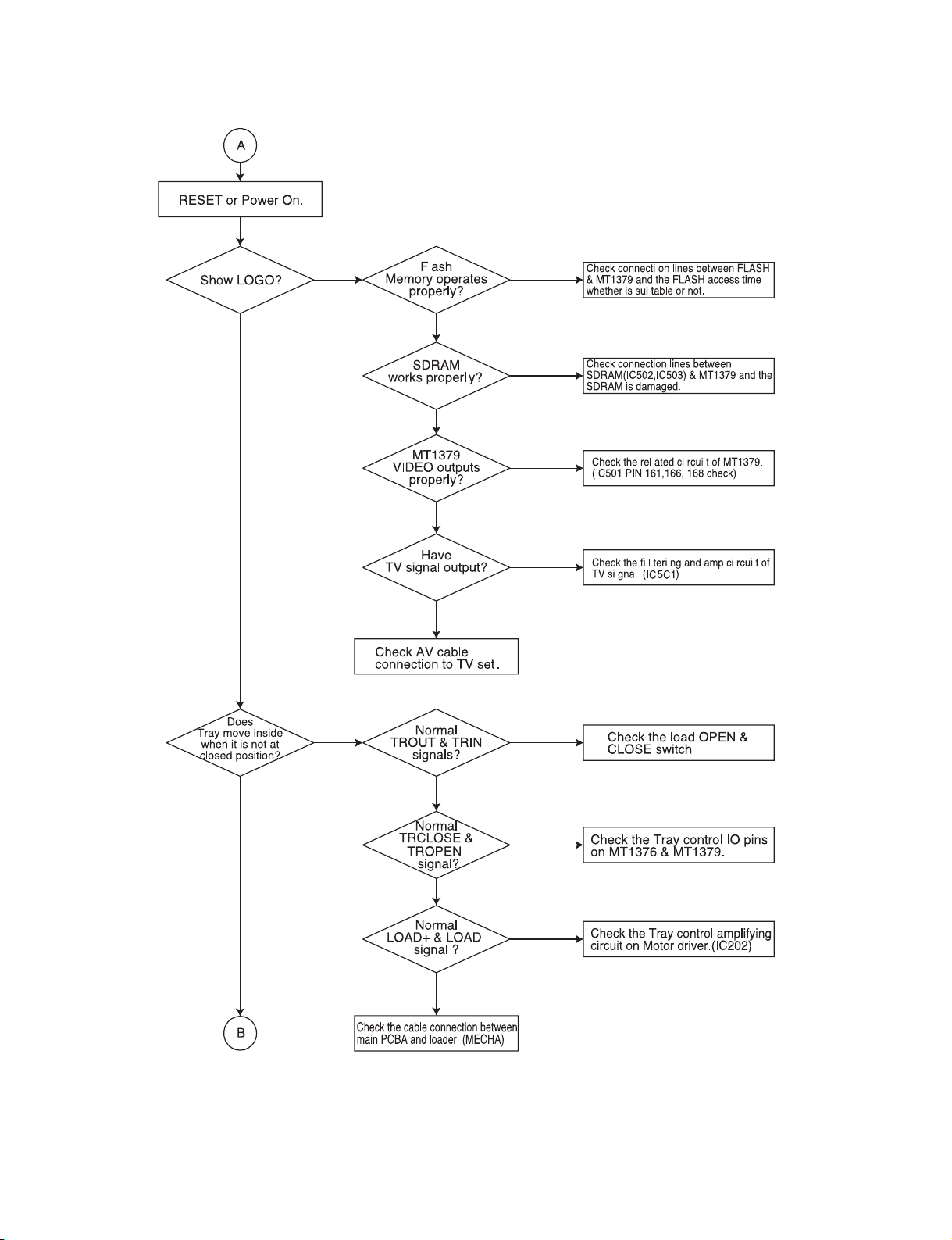
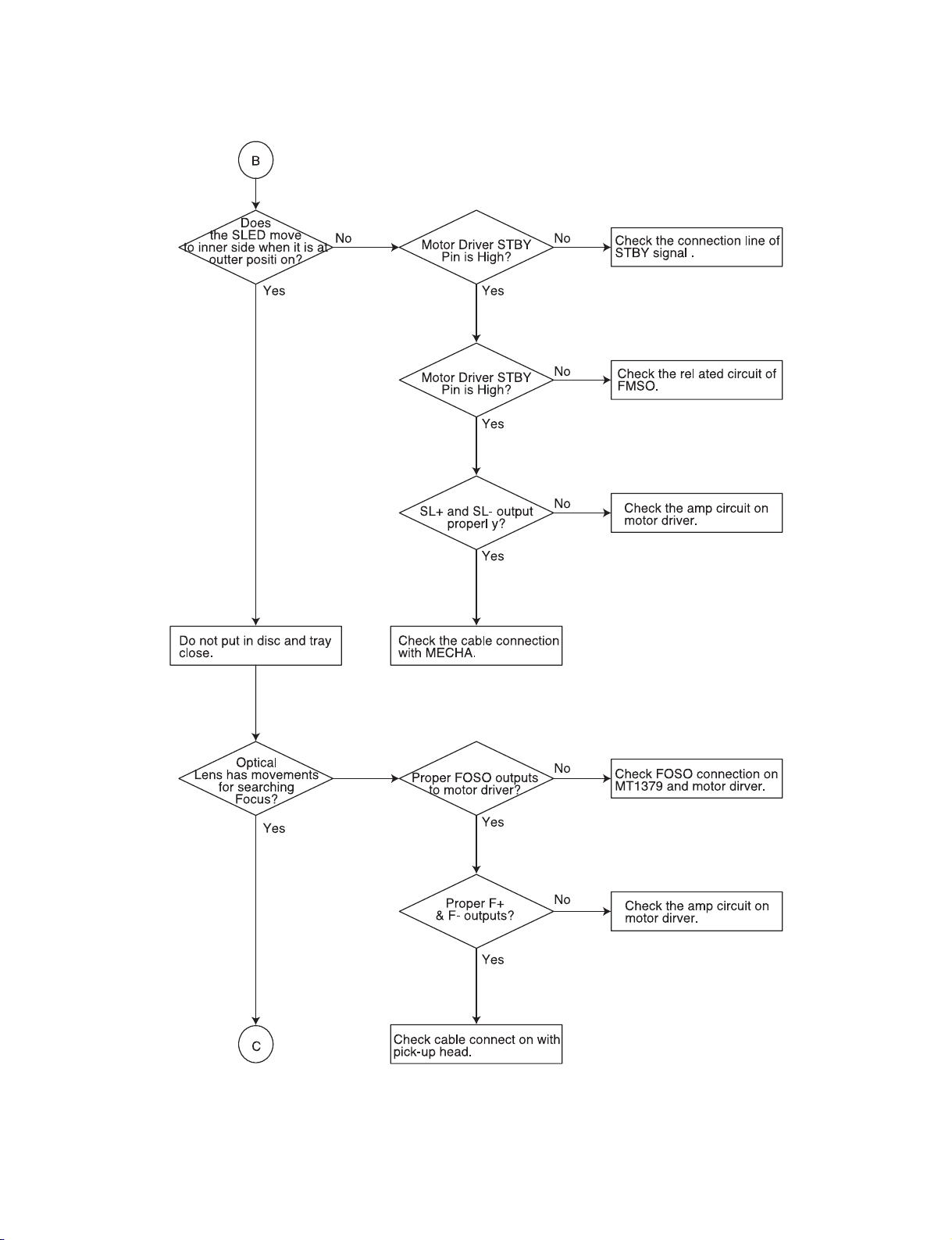
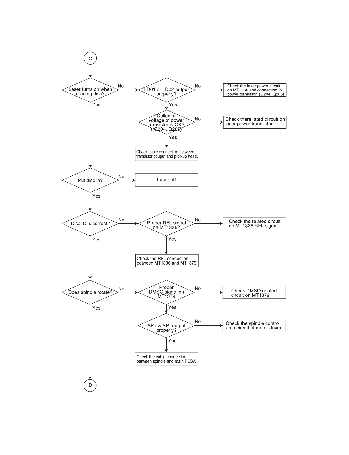
- 5-1 -
DVD ELECTRICAL TROUBLESHOOTING
1. Test & debug flow
SECTION 5. DVD PART
Page 28
- 5-2 -
Page 29
- 5-3 -
Page 30
- 5-4 -
Page 31

- 5-5 -
Page 32

- 5-6 -
Page 33

- 5-7 -
DETAILS AND WAVEFORMS ON SYSTEM TEST
AND DEBUGGING
1. SYSTEM 27MHz CLOCK,RESET,FLASH R/W SIGNAL
1) MT1379 main clock is at 27MHz(X501)
2) MT1336 reset is high active
Page 34

- 5-8 -
3) RS232 waveform during procedure(Downloading)
4) Flash R/W enable signal during download(Downloading)
Page 35

- 5-9 -
2. SDRAM CLOCK
1) MT1379 main clock is at 27MHz(X501)
3. TRAY OPEN/CLOSE SIGNAL
1) Tray open/close waveform
Page 36

- 5-10 -
2) Tray close waveform
3) Tray open waveform
Page 37

- 5-11 -
4. SLED CONTROL RELATED SIGNAL (NO DISC CONDITION)
5. LENS CONTROL RELATED SIGNAL(NO DISC CONDITION)
Page 38

- 5-12 -
6. LASER POWER CONTROL RELATED SIGNAL
(NO DISC CONDITION)
7. DISC TYPE JUDGEMENT WAVEFORM
Page 39

- 5-13 -
Page 40

- 5-14 -
8. FOCUS ON WAVEFORM
Page 41

- 5-15 -
9. SPINDLE CONTROL WAVEFORM (NO DISC CONDITION)
Page 42

- 5-16 -
10. TRACKING CONTROL RELATED SIGNAL(System checking)
Page 43

- 5-17 -
11. RF WAVEFORM
12. MT1379 AUDIO OPTICAL AND COAXIAL OUTPUT (ASPDIF)
Page 44

- 5-18 -
13. MT1379 VIDEO OUTPUT WAVEFORM
1) Full colorbar signal(CVBS)
2) Y
Page 45

- 5-19 -
3) C
14. AUDIO OUTPUT FORM AUDIO DAC
1) Audio related Signal
Page 46

- 5-20 -
MEMO
Page 47

- 7-3 -
• SPEAKER
Satellite speaker
• MODEL: LHS-C6230T
853
852
851
850
861
854
862
A800
LOCA.NO PART NO DESCRIPTION SPECIFICATION REMARKS
850 3701RM0042A NET ASSEMBLY SPK LHS-D6230T L.SILVER
851 6400FTTC02A SPEAKER,FULLRANGE F30C-D366 TOPTONE FULL-RANGE(H
853 3110RMP009A CASE REAR LH-6230TE MOLD STANDARD
854 6871RU4116B PWB(PCB) ASSEMBLY,SUBSET(AUDIO FE-3620TE 2P NEW TERMINAL 150M
855 6871RU9271A PWB(PCB) ASSEMBLY,SUBSET(AUDIO LHS-D6230T FRONT WIRE(5M) R CH
856 6871RU9271B PWB(PCB) ASSEMBLY,SUBSET(AUDIO LHS-D6230T FRONT WIRE(5M)/ L C
857 6871RU9271C PWB(PCB) ASSEMBLY,SUBSET(AUDIO LHS-D6230T CENTER WIRE(5M)/ (G
858 6871RU9271D PWB(PCB) ASSEMBLY,SUBSET(AUDIO LHS-D6230T REAR WIRE(10M) R/CH
859 6871RU9271E PWB(PCB) ASSEMBLY,SUBSET(AUDIO LHS-D6230T REAR WIRE(10M)/ L/C
861 353M025V SCREW,DRAWING + 2 D3.0 L6.0 MSWR3/FZB
862 353M025W SCREW,DRAWING + 2 D3.0 L14.0 MSWR3/FZB
A800 6401RM0045A SPEAKER ASSEMBLY F30C-D384-2 SHIN POONG LHS-D62
RUN DATE : 05.JUNE.2003
Page 48

Passive(Sub) Woofer
• MODEL: LHS-C6230W
852
854
855
853
851
861
LOCA.NO PART NO DESCRIPTION SPECIFICATION REMARKS
851 3720RMF045A PANEL,FRONT FRONT LH-6230WE STANDARD
852 3701RM0043A NET ASSEMBLY SPK LHS-D6230W SILVER STANDARD
853 3091RMW050A CABINET ASSEMBLY ASSY LH-6230WE ALL PB 9T
854 6400WTTJ03A SPEAKER,WOOFER F65C-D365 TOPTONE WOOFER LHS-6
855 6871RU9271F PWB(PCB) ASSEMBLY,SUBSET(AUDIO LHS-D6230W SUB WOOFER 2.5M, OR
861 353M050C SCREW BH 3.5X16 FBK
RUN DATE : 05.JUNE.2003
- 7-4 -
Page 49

BLOCK DIAGRAM
2-2 2-3
Page 50

AUDIO SHEMATIC DIAGRAMS
• U-COM SCHEMATIC DIAGRAM
2-4 2-5
Page 51

• FUNCTION & POWER SCHEMATIC DIAGRAM
2-6 2-7
Page 52

• MAIN AMP SCHEMATIC DIAGRAM
2-8 2-9
Page 53

WIRING DIAGRAM
2-10 2-11
Page 54

AUDIO VOLTAGE SHEET (IC&TR)
[FRONT] [MAIN]
LOC. PART PIN NUM. STOP DVD PLAY
IC501 LC87F57C 1 4.2 4.2
2 5 5
3 0 0
4 0 0
5 0 0
6 0 0
7 0 0
8 0 0
9 5 5
10 0 0
11 0 0
12 0 0
13 0 0
14 0 0
15 0 0
16 0 0
17 0 0
18 0 0
19 5 5
20 2.5 2.5
21 2.5 2.5
22 2.5 2.5
23 2.5 2.5
24 5 5
25 2.5 2.5
26 4.6 4.6
27 2.5 4.6
28 2.5 2.3
29 2.5 2.5
30 2 2.5
31 5 5
32 0 0
33 5 0
34 0 0
35 0 0
36 5 5
37 0 0
38 0 0
39 0 0
40 0 0
41 0 0
42 0 2.3
43 0 0
44 0 2.3
45 0 2.3
46 5 5
47 0.3 2.3
48 0.3 2.3
49 2.5 2.3
50 0 2.3
51 4.4 4.4
52 0.3 0
53 5 5
54 0.3 0.5
55 0.3 0
56 0 0
LOC. PART PIN NUM. STOP DVD PLAY
57 2.3 2.3
58 2.3 2.3
59 4.9 5
60 0 0
61 0 0
62 0 0
63 0 0
64 4 4
LOC. PART PIN NUM. STOP DVD PLAY
IC707 KIA7805 1 11.9 11.9
200
355
IC703 KIA7812 1 18.4 18.4
200
3 11.9 11.9
IC701 KIA7909 1 0 0
2 -18.6 -18.6
3-9-9
IC702 KA7809 1 18.4 18.4
200
399
IC704 KA78R12 1 18.4 18.4
21212
300
455
IC706 KIA7805 1 11 11
200
355
IC705 KIA7805 1 11 11
200
355
D507 D5402 ANODE -0.2 -0.2
CATHODE 11 11
D511 D5402 ANODE -0.2 -0.2
CATHODE 11 11
BD501 KBU6G 1 -18.6 -18.6
200
300
4 18.4 18.4
IC101 KIA4580 1 4.5 4.5
2 4.5 4.5
3 4.5 4.5
400
5 4.5 4.5
6 4.5 4.5
7 4.5 4.5
899
IC102 CS5331A 1 1.4 1.4
2 1.6 1.6
3 1.6 1.6
4 1.5 1.5
5 2.2 2.2
600
755
8 2.2 2.2
IC103 4052 1 0 0
200
300
400
500
600
7 -4.5 -4.5
800
900
10 0 0
LOC. PART PIN NUM. STOP DVD PLAY
11 0 0
12 0 0
13 0 0
14 0 0
15 0 0
16 4.5 4.5
IC105 M60446AFP 5 5.2 5.2
30 -5.3 -5.3
42 5 5
IC200 TDA7265 1 -18.7 -18.7
200
3 18.6 18.6
400
5 9.3 9.3
6 -18.6 -18.6
700
800
900
10 0 0
11 0 0
IC250 TDA7265 1 -18.7 -18.7
200
3 18.6 18.6
400
5 9.3 9.3
6 -18.6 -18.6
700
800
900
10 0 0
11 0 0
IC300 TDA7265 1 -18.7 -18.7
200
3 18.6 18.6
400
5 9.3 9.3
6 -18.6 -18.6
700
800
900
10 0 0
11 0 0
IC400 TDA7265 1 -18.7 -18.7
200
3 18.6 18.6
400
5 9.3 9.3
6 -18.6 -18.6
700
800
900
10 0 0
11 0 0
2-12 2-13
Page 55

PRINTED CIRCUIT DIAGRAM
• MAINAMP & FRONT P.C. BOARD (SOLDER SIDE)
2-14 2-15
Page 56

• MAINAMP & FRONT P.C. BOARD (COMPONENT SIDE)
2-16 2-17
Page 57

• FUNCTION & POWER P.C. BOARD (SOLDER SIDE)
2-18 2-19
Page 58

• FUNCTION & POWER P.C. BOARD (COMPONENT SIDE)
2-20 2-21
Page 59

VCR SHEMATIC DIAGRAMS
• SYSTEM SCHEMATIC DIAGRAM
3-17 3-18
Page 60

• A(AUDIO)/V(VIDEO) SCHEMATIC DIAGRAM
3-19 3-20
Page 61

• POWER SCHEMATIC DIAGRAM
NOTE: Warning
Parts that are shaded are critical With respect
to risk of fire or electrical shock.
NOTE:
1. Shaded(■) parts are critical for safety.Replace only
with specified part number.
2. Voltages are DC-measured with a digital voltmefer
during Play mode.
3-21 3-22
Page 62

• TU/IF. ACSS SCHEMATIC DIAGRAM
3-23 3-24
Page 63

• HIFI/TUNER SCHEMATIC DIAGRAM
3-25 3-26
Page 64

• A/V JACK, SCART SCHEMATIC DIAGRAM
3-27 3-28
Page 65

VCR VOLTAGE SHEET (IC&TR)
MODE
PIN NO.
1 0.9 0 2.2 2.17 0 0 1.78 2.78
2 4.85 4.85 2.2 2.17 0 2.53 0 0
3 0 0 2.2 2.17 9.12 9.06 2.85 2.84
4 0.1 0.1 2.2 2.17 2.48 2.48 0 0
5 0.1 0.1 2.2 2.19 4.8 4.79 2.8 2.83
6 0 0 2.2 2.2 0 2.08 4.73 4.71
7 0.1 0 2.2 0 1.76 0 2 2.02
8 0.1 0 2.2 2.2 0 2.2 0 0
9 0.3 0.9 2.2 2.2 0 0
10 0.68 0.85 2.2 2.2 0 0
11 0.02 3.19 4.7 4.67 0 2.5
12 0.02 0 0.99 0.98 2.5 2.66
13 0.02 0 0.99 0.96 1.72 2.5
14 3.8 3.8 1.85 1.76 2.5 4.74
15 0 2.3 1.54 0.36 4.76 2.52
16 4.47 0 0 0 2.52 0
17 0.15 0 2 2.44 0 0.39
18 4.77 2.38 2.4 2.47 0.56 2.66
19 4.77 2.38 0 0 2.52 2.66
20 4.06 0 2.4 3.33 2.52 2.66
21 4.05 0.1 1.7 2.55 2.52 2.66
22 0 4.85 2.8 3.09 2.52 0
23 0 4.82 4.7 4.7 0.17 2.07
24 0 0 0 0 2.02 0
25 4.84 0 4.03 0 0 2.07
26 4.77 2.5 2.15 2.2 2.02 2.07
27 0 0 1.46 1.8 2.02 0
28 0 0 2.13 2.1 0 0
29 0 0 1.7 2.24 3.33 2.84
30 0 0 2.13 2.13 0 2.84
31 2.5 2.6 4 4 2.52 3.56
32 4.19 4.17 2.13 2.13 4.72 4.71
33 4.23 4.17 2.35 2.35 2.35 2.33
34 0 0 2.8 3.1 2.35 0
35 1.48 1.5 2.77 2.82 0 0
36 1.48 1.4 2.1 2.1 4.76 4.74
37 4.29 4.7 2.17 2.66 4.76 4.74
38 2 2 0 0 4.76 4.74
39 2.11 2 1.72 1.23 4.76 2.33
40 0 0 0 0 4.6 0
41 0 0.1 0.84 0.83 2.52 2.64
42 0 0 2.15 2.15 2.52 2.61
43 0 0 0 0 2.54 2.65
44 2.1 2.2 4.69 4.67 2.54 2.65
45 2.2 2.2 4.72 4.7 0.57 0.41
46 0 0 2.11 2.94 4.76 4.74
47 1.3 1.2 2.84 3.65 2.5 0
48 0 0 2.8 4.23 1.75 2.62
49 0 0 3.79 3.77 3.78 0
50 0.9 2.3 0 2.29 0 0
51 0 0.2 2.11 2.1 1.79 0
52 1.5 2.3 0 4.7 1.22 0
53 4.7 4.7 4.18 4 3.81 0
54 0 1.9 4.18 4.8 9.12 9.06
55 2.17 2.7 0.68 0.8 6.22 0.22
IC501 IC301 IC801 IC302
STOP PLAY STOP PLAY STOP PLAY STOP PLAY
MODE
PIN NO.
56 0.9 2.2 0 0 2.96 0.23
57 0 0 3.07 2.36 2.16 2.1
58 0 0 4.43 0 4.53 0
59 0 0 0.35 0.29 2.54 2.53
60 2.5 2.3 0.65 0.19 3.81 0
61 4.6 4.5 1.07 2.23 3.13 0.22
62 4.3 4.3 0 0 3.86 0
63 4.4 0.1 3.72 3.7 3.8 0
64 0 0.1 0.97 1.23 2.45 0
65 1.1 0.8 1.66 0.72 3.84 0.29
66 4.7 4.75 1.66 0.72 4.03 0.3
67 4.7 4.75 1.66 0.72 3.85 0.3
68 4.7 3.8 1.66 4.62 3.85 0.3
69 4.7 4.7 4.7 4.68 0 0
70 4.2 4.1 0 0 0 0
71 4.8 4.76 0 0 0 0
72 4.8 4.76 1.65 1.65 3.85 0.3
73 4.4 4.4 1.65 1.65 3.85 0
74 0 0 1.65 1.65 0 2.49
75 4.7 0 0 0 3.85 0.2
76 0 2.4 2.19 0 3.15 0.2
77 0 2.4 4.72 4.7 0 0
78 4.5 4.4 2.19 2.18 4.45 4.33
79 4.6 4.6 0 0 0 0
80 0 3.2 2.19 2.18 4.45 4.32
81 0 0
82 3.3 3.3
83 4.4 0
84 0 0
85 1.3 1.2
86 0 1.2
87 3.5 2.18
88 0 0
89 0 0.19
90 0 1.25
91 2.3 2.35
92 0 2.35
93 0 0
94 2.3 2.32
95 2.3 2.32
96 0 2.34
97 0.6 0
98 4.7 4.69
99 0 4.77
100 0.6 0.8
IC501 IC301 IC801 IC302
STOP PLAY STOP PLAY STOP PLAY STOP PLAY
3-29 3-30
Page 66

PRINTED CIRCUIT DIAGRAMS
• TUNER P.C BOARD
3-31 3-32
Page 67

• VCR P.C BOARD
3-33 3-34
Page 68

• VCR P.C BOARD
3-35 3-36
Page 69

DVD PART SCHEMATIC DIAGRAMS
• MPEG SCHEMATIC DIAGRAM
5-225-21
Page 70

• SERVO SCHEMATIC DIAGRAM
5-23 5-24
Page 71

• AUDIO SCHEMATIC DIAGRAM
5-25 5-26
Page 72

• INTERFACE SCHEMATIC DIAGRAM
5-27 5-28
Page 73

VOLTAGE SHEET (IC&TR)
5-29 5-30
Page 74

PRINTED CIRCUIT DIAGRAM
• DVD P.C. BOARD(SOLDER SIDE)
5-31 5-32
Page 75

• DVD P.C. BOARD (COMPONENT SIDE)
5-33 5-34
Page 76

A48
A26
265
A49
A00
A45
A46
285
A47
250
330
276
A42B
A42
284
277
267
A43
283
300
320
264
260
321
AUDIO TUNER
SECTION 7. EXPLODED VIEWS
• CABINET AND MAIN FRAME
NOTE) Refer to “SECTION 7 REPLACEMENT
PARTS LIST” in order to look for the
part number of each part.
7-1 7-2
Page 77

SECTION 4. MECHANSIM OF VCR PART
Page 78

- 4-1 -
DECK MECHANISM PARTS LOCATIONS
4
6
3
2
7
9
5
11
18
16
19
17
19
12
13
15
10
1
31
14
8
15
33
Top View
Bottom View
20
24
23
20
24
22
21
29
30
29
30
25
32
27
26
28
NOTE : When reassembly perform the
procedure in the reverse order.
1 Drum Assembly 3 Screw A-1 T
2 Plate Top 2 Hook A-2 T
2 3 Holder Assembly CST Chassis Hole A-2 T
2 4 Opener Door Chassis Hole A-2 T
5 Bracket Assembly 3 Hook A-2 T
L/D Motor
2,3,4 6 Gear Assembly Rack F/L 1 Hook, Chassis Hole A-2 T
2,3,4,6 7 Arm Assembly F/L Chassis Hole A-2 T
8 Lever Assembly S/W 1 Hook A-2 T
9 Arm Assembly Cleaner Chassis Embossing A-3 T
10 Head F/E Chassis Embossing A-3 T
11 Base Assembly A/C Head 1 Screw A-3 T
2,3 12 Brake Assembly T 1 Hook A-4 T
2,3 13 Brake Assembly RS 1 Hook A-4 T
2,3 14 Arm Assembly Tension 2 Hook A-4 T
2,3,12,13, 15 Reel S/Reel T A-4 T
14
16 Base Assembly P4 Chassis Embossing A-5 T
17 Opener Lid Chassis Embossing A-5 T
17 18 Arm Assembly Pinch Shaft A-5 T
17 19 Lever T/Up / Arm T/Up 1 Hook A-5 T
17,18 20
Belt Capstan/Motor Capstan
3 Screw A-6 B
21 Lever F/R Locking Tab A-6 B
20, 21 22 Clutch Assembly D35 Washer A-6 B
23 Brake Assembly Capstan Locking Tab A-6 B
24 Gear Drive/Gear Cam Washer/Hook A-7 B
25 Gear Sector 1 Hook A-7 B
20,21,23, 26 Plate Slider Shaft Guide A-7 B
24,25
20,21,23, 27 Lever Tension 1 Hook A-7 B
24,25,26
2,3,14,20, 28 Lever Spring Locking Tab A7 B
21,25,23,
24,26
25 29
Gear Assembly P2/Gear Assembly P3
Boss A-8 B
2,3,14,25, 30
Base Assembly P2/Base Assembly P3
Chassis Slot A-8 B
29
2,3,14,25, 31 Base Loading 1 Screw A-9 T
29
2,3,14 32 Base Tension Chassis Embossing A-9 B
2,3,20,21, 33 Arm Assembly Idler Locking Tab A-9 T
22
Starting
No.
Procedure
Part Fixing Type
Fig-
ure
View
1) When reassembling, confirm Mechanism and Mode
Switch Alignment Position (Refer to Page 4-13)
2) When disassembling, the Parts for Starting No. Should
be removed first.
T:Top, B:Bottom
Page 79

- 4-2 -
DECK MECHANISM DISASSEMBLY
(S3)
(S2)
(S2)
(S3)
(A)
Stator
Carbon Brush
Drum Motor
Rotor
Drum Sub Assembly
Drum FPC
(S1)
(S1)
(S1)
Holder FPC
H1
H2
1. Drum Assembly (Fig. A-1-1)
1) Unplug the Drum FPC Connector.
2) Remove three Screws(S1) on bottom side and separate
the Drum assembly.
3) Unhook (H1), (H2) and separate the Holder FPC and
Cap FPC.
1-1. Drum Motor
1) Remove two Screws(S2) and disassemble the Stator of
the Drum Motor.
2) Remove two Screws(S3) and separate the Rotor of the
Drum Motor from the Drum Sub assembly.
NOTE
When reassembling, confirm (A) portion of the Drum Sub
assembly whether the Carbon Brush is in there or not.
Fig. A-1
(Fig. B-1)
Holder FPC
Drum FPC
Cap FPC
Figure in the opposite direction
(Fig. A-1-1)
Page 80

- 4-3 -
DECK MECHANISM DISASSEMBLY
(B)
(E)
(C1)
(C)
Plate Top
Arm Assembly F/L
Spring Lever S/W
Gear Assembly Rack F/L
Chassis
Opener Door
Bracket Assembly L/D Motor
Holder Assembly CST
(B’)
(C’)
(D)
(E’)
(H6)
(A)
(B)
Lever Assembly S/W
(H8)
Fig. A-2
(Fig. A-2-1)
(Fig. A-2-2)
(Fig. A-2-6)
(Fig. A-2-7)
(Fig. A-2-5)
(Fig. A-2-3)
(Fig. A-2-4)
Page 81

- 4-4 -
DECK MECHANISM DISASSEMBLY
2. Plate Top (Fig. A-2-1)
1) Pull the (B) portion of the Plate Top back in direction of
arrow and separate the right side of it.
2) pull the (B ) portion of the Plate Top back in direction of
arrow and separate the left side of it.
(Used tools : (-) type driver, anything tool with sharp
point or flat point.)
NOTE
(1) When reassembling, push the Plate Top after alignment
the two position(C), (C ) as below Fig.
3. Holder Assembly CST (Fig.A-2-2)
1) Move the Holder Assembly CST in direction of arrow and
separate the left side of it first through the (D) position of
the Chassis.
2) Disassemble the right side of the Holder Assembly CST
from each guided hole of the Chassis.
NOTE
When reassembling, insert the (E) part of the Holder
Assembly CST in the (E ) hole of the Chassis first and
assemble the left side of it.
4. Opener Door (Figure. A-2-3)
1) Turn the Opener Door clockwise and remove it through
the guide hole of the Chassis.
5. Bracket Assembly L/D Motor
(Fig. A-2-4)
1) Unplug the Connector(C1).
2) Unhook three Hooks(H3, H4, H5) on bottom side of the
Chassis, lift up the Bracket Assembly L/M and disassemble the Bracket Assembly L/D Motor.
6. Gear Assembly Rack F/L (Fig. A-2-5)
1) Move the Gear Assembly Rack F/L in direction of
arrow(A) and unhook the Hook(H6) pulling back in front.
2) Separate the Gear Rack F/L in direction of arrow(B).
NOTE
When reassembling, align the gear part of the Gear
Assembly Rack F/L with the Gear Drive as below Fig.
7. Arm Assembly F/L (Fig. A-2-6)
1) Move the Arm Assembly F/L in direction of arrow and
separate the left side of it first.
2) Disassemble the Arm Assembly F/L from each guided
hole of the Chassis.
8. Lever Assembly S/W(Fig. A-2-7)
1) Unhook the Hook(H8) in the left side of the Chassis and
remove the Lever Assembly S/W.
(B’)
(C’)
(C)
(B)
(D)
Holder assembly CST
Chassis
Gear Rack F/L
Gear Drive
(H8)
Chassis
(H3)
(H4)
(H5)
Bracket assembly L/M
Page 82

- 4-5 -
DECK MECHANISM DISASSEMBLY
9. Arm Assembly Cleaner (Fig. A-3-1)
1) Breakaway the (A) portion as Fig. A-3-1 from the
embossing of the Chassis, turn the Arm assembly
Cleaner to clockwise direction and lift it up.
10. Head F/E (Fig. A-3-2)
1) Breakaway the (A) portion of the Head F/E from the
embossing of the Chassis, turn it to counterclockwise
direction and lift it up.
11. Base Assembly A/C Head (Fig. A-3-3)
1) Remove the Screw(S4) and lift the Base Assembly A/C
Head up.
(A)
Arm Assembly
Cleaner
Base Assembly A/C Head
(S4)
Head F/E
(A)
Chassis
Fig. A-3
(Fig. A-3-1)
(Fig. A-3-3)
(Fig. A-3-2)
Page 83

- 4-6 -
DECK MECHANISM DISASSEMBLY
Brake Assembly T
Spring TB
(H9)
Reel T
Brake Assembly RS
Spring RS
Arm Assembly Tension
Spring Tension
Reel S
Base Tension
(H11)
(H12)
Chassis
(H10)
Fig. A-4
12. Brake Assembly T (Fig. A-4-1)
1) Unhook the Spring TB from the Hook(H9) of the Chassis.
2) Lift the Brake Assembly T up.
13. Brake Assembly RS (Fig. A-4-2)
1) Unhook the Spring RS from the Hook(H10) of the
Chassis.
2) Lift the Brake Assembly T up.
14. Arm Assembly Tension (Fig. A-4-3)
1) Unhook the Spring Tension from the Hook(H11) of the
Arm Assembly Tension.
2) Unhook the Hook(H12) of the Base Tension and lift the
Arm Assembly Tension up.
NOTE
Difference for Springs
15. Reel S / Reel T (Fig. A-4-4)
1) Difference for Reel S / Reel T
Spring TB
Spring RS
Color (Black)
Spring Tension
Reel S Reel T
(Fig. A-4-1)
(Fig. A-4-3)
(Fig. A-4-4)
(Fig. A-4-4)
(Fig. A-4-2)
Page 84

- 4-7 -
DECK MECHANISM DISASSEMBLY
Fig. A-5
16. Base Assembly P4 (Fig. A-5-1)
1) Breakaway the (A) portion of the Base Assembly P4 from
the embossing of the Chassis.
2) Turn the Base Assembly P4 to counterclockwise direction
and lift it up.
17. Opener Lid (Fig. A-5-2)
1) Breakaway the (B) portion of the Opener Lid from the
embossing of the Chassis.
2) Turn the Opener Lid to clockwise direction and lift it up.
18. Arm Assembly Pinch (Fig. A-5-3)
1) Lift the Arm Assembly Pinch up.
NOTE
When reassembling, confirm the (C) portion of the Arm
Assembly Pinch is inserted to the Chassis hole correctly as
Fig.
19. Lever T/up (Fig. A-5-4)/
Arm T/up (Fig. A-5-5)
1) Unhook the Hook(H13) of the bottom Chassis and lift the
Lever T/up up.
2) Lift the Arm T/up up.
(Fig. A-5-2)
(Fig. A-5-1)
(Fig. A-5-3)
(Fig. A-5-5)
(Fig. A-5-4)
(B)
Base Assembly P4
(B)
Opener Lid
Arm
Assembly
Pinch
(C)
(C)
Lever T/up
(H13)
(A)
Arm T/up
(H13)
Chassis
Page 85

- 4-8 -
DECK MECHANISM DISASSEMBLY
Chassis
(S5)
Belt Capstan
Motor Capstan
Washer(W1)
Lever F/R
Clutch Assembly D35
Brake Assembly Capstan
(L1)
(L2)
(L1)
Fig. A-6
20. Belt Capstan (Fig. A-6-1)/
Motor Capstan (Fig. A-6-2)
1) Remove the Belt Capstan.
2) Remove the three Screws(S5) on bottom Chassis and lift
the Motor Capstan up.
21. Lever F/R (Fig. A-6-3)
1) Unlock the Locking Tab(L1) as Fig. A-6-3 and lift the
Lever F/R up.
22. Clutch Assembly D35 (Fig. A-6-4)
1) Remove the Washer(W1) and lift the Clutch Assembly
D35 up.
23. Brake Assembly Capstan
(Fig. A-6-5)
1) Pull the Locking Tab(L2) back in direction of arrow and lift
it up.
(Fig. A-6-1)
(Fig. A-6-2)
(Fig. A-6-3)
(Fig. A-6-5)
(Fig. A-6-4)
Page 86

- 4-9 -
DECK MECHANISM DISASSEMBLY
Gear Drive
Washer (W2)
Gear Cam
Plate Slider
Lever Tension
Lever spring
Base Loading
Gear Sector
(L3)
(H15)
(H16)
(H14)
(A)
Chassis
Gear Drive Hole(C)
Gear Cam Hole(B)
Gear Drive Hole(A)
Fig. A-7
24. Gear Drive (Fig. A-7-1)/
Gear Cam (Fig. A-7-2)
1) Remove the Washer(W2) and lift the Gear Drive up.
2) Unhook the Hook(H14) of the Gear Cam and lift the Gear
Cam up.
NOTE
When reassembling, align the Gear Drive Hole(A) and the
Gear Cam Hole(B) in a straight line after the Gear Drive
Hole(C) is aligned with the Chassis Hole as Fig.
25. Gear Sector (Fig. A-7-3)
1) Unhook the Hook(H15) of the Base Loading on bottom
Chassis and lift the Gear Sector up.
26. Plate Slider (Fig. A-7-4)
1) Just lift the Plate Slider up.
27. Lever Tension (Fig. A-7-5)
1) Unhook the (A) portion of the Lever Tension from the
Hook(H16) of the Chassis.
2) Turn the Lever Tension to counterclockwise direction and
lift it up.
28. Lever Spring (Fig. A-7-6)
1) Unlock the Locking Tab(L3) of the bottom Chassis and lift
the Lever Spring up.
(Fig. A-7-4)
(Fig. A-7-5)
(Fig. A-7-6)
(Fig. A-7-1)
(Fig. A-7-2)
(Fig. A-7-3)
Page 87

- 4-10 -
DECK MECHANISM DISASSEMBLY
Gear Assembly P3
Gear Assembly P2
Base Assembly P2
Base Assembly P3
(A)
(B)
Chassis
Gear Assembly P2 Hole
Gear Sector Hole(A)
Plate Slider Hole(B)
Lever Spring Boss
Gear Assembly P3 Hole
Fig. A-8
29. Gear Assembly P2 (Fig. A-8-1)/
Gear Assembly P3 (Fig. A-8-2)
1) Just lift the Gear Assembly P2 up.
2) Just lift the Gear Assembly P3 up.
NOTE
When reassembling, align the two holes of the Gear
Assembly P2 and P3 in a straight line after confirmation
whether the Gear Sector Hole(A) and the Plate Slider
Hole(B) are aligned or not as Fig.
30. Base Assembly P2 (Fig. A-8-3)/
Base Assembly P3 (Fig. A-8-4)
1) Move the Base Assembly P2 in direction of arrow(A)
along the guide hole of the Chassis and disassemble it
on bottom side.
2) Move the Base Assembly P3 in direction of arrow(B)
along the guide hole of the Chassis and disassemble it
on bottom side.
(Fig. A-8-1)
(Fig. A-8-2)
(Fig. A-8-3)
(Fig. A-8-4)
Page 88

- 4-11 -
DECK MECHANISM DISASSEMBLY
Fig. A-9
31. Base Loading (Fig. A-9-1)
1) Remove the Screw(S7).
2) Lift the Base Loading up.
32. Base Tension (Fig. A-9-2)
1) Breakaway the (A) portion of the Base Tension from the
embossing of the Chassis.
2) Turn the Base Tension to counterclockwise direction and
lift it up.
33. Arm Assembly Idler (Fig. A-9-3)
1) Make narrower the two parts, (B) and (C), as Fig. A-9-3.
2) Lift the Arm assembly Idler up.
NOTE
When disassembling, be careful not to be caught the (D) part
by the Chassis as Fig.
(Fig. A-9-1)
(Fig. A-9-2)
(Fig. A-9-3)
Base Tension
(A)
(S7)
Base Loading
Arm Assembly Idler
(B) (C)
(D)
Chassis
Page 89

- 4-12 -
Page 90

- 4-13 -
DECK MECHANISM ADJUSTMENT
Purpose:To determine if the Mechanism is in the correct position, when a Tape is ejected.
1. Mechanism Alignment Position Check
1) Turn the Power S/W on and eject the Cassette by pressing the Eject Button.
2) Remove the Top Cover and Plate Assembly Top, visually check if the Gear Cam Hole is aligned with the
Chassis Hole as below Fig. C-2.
3) IF not, rotate the Shaft of the Loading Motor to either
clockwise or counterclockwise until the alignment is as
below Fig. C-2.
4) Remove the Screw which fixes the Deck Mechanism and
Main Frame and confirm if the Gear Cam is aligned with
the Gear Drive as below Fig. C-1(A).
5) Confirm if the Mode S/W on the Main P.C.Board is
aligned as below Fig. C-1(B).
6) Remount the Deck Mechanism on the Main P.C.Board
and check each operation.
Gear Cam
Gear Drive
(A)
Mode S/W
(B)
L/D Motor Assembly
Gear Cam
Chassis Hole
Gear Cam Hole
(A)
(B)
(A’)
(B’)
Gear Drive Hole
Test Equipment/ Fixture
Blank tape
Test Conditions (Mechanism
Condition)
Eject Mode (with Cassette ejected)
Check Point
Mechanism and Mode Switch Position
Fig. C-1
Fig. C-2
CHECK DIAGRAM
BOTTOM VIEW
TOP VIEW
Gear Cam (o) and Gear Drive (o) groove alignment
Page 91

- 4-14 -
DECK MECHANISM ADJUSTMENT
Purpose: To insure smooth transport of the tape during each mode of operation.
If the tape transport is abnormal, then check the torque as indicated by the chart below.
2. Preparation for Adjustment (To set the
Deck Mechanism of the loading state
without inserting a cassette tape).
1) Unplug the power cord from the AC outlet.
2) Disassemble the Top Cover and Plate Assembly Top.
3) Plug the power cord into the AC outlet.
4) Turn the power S/W on and push the Lever Stopper of
the Holder Assembly CST to the back for loading the
cassette without tape.
Cover the holes of the End Sensors at the both sides of
the Chassis to prevent a light leak.
Then the Deck Mechanism drives to the Stop Mode.
In this case, the Deck Mechanism can accept inputs of
each mode, however the Rewind and Review operation
can not be performed for more than a few seconds
because the Take-up Reel Table is in the Stop State
and can not be detected the Reel Pulses.
3. Checking Torque
NOTE:
The values are measured by using a Torque Gauge and
Torque Gauge Adaptor with the Torque Gauge affixed.
NOTE:
The torque reading to measure occurs when the tape
abruptly changes direction from Fast Forward to Rewind
Mode, when quick braking is applied to both Reels.
S
R
K
VIDEO
CASSETTE
TORQUE
METER
VHT-303
S
R
K
-
V
H
T
-
S
S
R
K
-
V
H
T
T
300
250
200
150
50
0
300
250
200
150
50
0
100
Test Equipment/ Fixture
¥ Torque Gauge(600g/cm ATG)
¥ Torque Gauge Adaptor
¥ Cassette Torque Meter
SRK-VHT-303
Checking Method
¥ Perform each Deck Mechanism mode without
inserting a cassette tape(Refer to above No.2
Preparation for Adjustment).
¥ Read the measurement of the Take-up or Supply
Reels on the Cassette Torque Meter(Fig. C-3-2).
¥ Attach the Torque Gauge Adaptor to the Torque
Gauge and then read the value of it(Fig. C-3-1).
Fig. C-3-2
Fig. C-3-1
Torque Gauge
Torque Gauge
Adaptor
Reel Table
Item
Fast Forward Torque
Rewind Torque
Play Take-Up Torque
Review Torque
Mode
Fast Forward
Rewind
Play
Review
Test Equipment
Cassette Torque Gauge
Cassette Torque Gauge
Cassette Torque Meter
Cassette Torque Meter
Measurement Reel
Take-Up Reel
Supply Reel
Take-Up Reel
Supply Reel
Measurement Values
More than 400g/cm
More than 400g/cm
40~100g/cm
120~210g/cm
Test Conditions
(Mechanism Condition)
¥ Play (FF) or Review (REW) Mode
¥ Cassette Torque Meter (SRK-VHT-303)¥ Torque Gauge (600g.cm ATG)
Page 92

- 4-15 -
DECK MECHANISM ADJUSTMENT
4.Guide Roller Height Adjustment
Adjustment Procedure
1) Confirm if the tape runs along the tape guide line of the
Lower Drum.
2) If the tape runs the bottom of the guide line, turn the
Guide Roller Height Adjustment Screw to clockwise
direction.
3) If it runs the top, turn to counterclockwise direction.
4) Adjust the height of the Guide Roller to be guided to the
guide line of the Lower Drum from the starting and ending point of the Drum.
Purpose: To regulate the height of the tape so that the bottom of the tape runs along the
tape guide line on the Lower Drum.
Test Equipment/ Fixture
Post Height Adjusting Driver
Test Conditions (Mechanism Condition)
Play or Review Mode
Adjustment Point
Guide Roller Height Adjustment
screws on the Supply and Take-Up
Guide Rollers.
Fig. C-4-1
Upper Flange
Guide Roller
Retaining Screw
Guide Roller Height
Adjustment screw
ADJUSTMENT DIAGRAM
Test Equipment/Fixture
Oscilloscope
Alignment Tape
Post Height Adjusting
Driver
Test Equipment Connection Points
CH-1:PB RF Envelope
CH-2:NTSC: SW 30Hz
PAL: SW 25Hz
Head Switching Output
Point
RF Envelope Output
Point
Test Conditions VCR(VCP) State
Play an Alignment Tape
Adjustment Point
Guide Roller Height
Adjustment Screws
Fig. C-4-2
Fig. C-4-3
P3 POST
ADJUSTMENT
P2 POST
ADJUSTMENT
Turn the Roller Guide Height
Adjustment Screw slightly
to flatten the waveform.
Tracking Control at center
RF ENVELOPE OUTPUT TEST POINT
OSCILLOSCOPE
HEAD SWITCHING OUTPUT TEST
POINT
Turn(Move) the Tracking
Control to both directions
4-1. Preliminary Adjustment
4-2. Precise Adjustment
Adjustment Procedure
1) Play an Alignment Tape after connecting the probe of the
Oscilloscope to the RF Envelope Output Test Point and
Head Switching Output Test Point.
2) Tracking Control(in PB Mode) : Center Position(When
this adjustment is performed after the Drum Assembly
has been replaced, set the Tracking Control so that the
RF Output is Maximum).
3) Height Adjustment Screw : Flatten the RF waveform.
(Fig. C-4-2)
4) Turn(Move) the Tracking Control(in PB Mode) clockwise
and counterclockwise.(Fig. C-4-3)
5) Check that any drop of RF Output is uniform at the start
and end of the waveform.
NOTE
If the adjustment is excessive or insufficient the tape will
jam or fold.
Waveform Diagrams
Connection Diagram
Page 93

- 4-16 -
DECK MECHANISM ADJUSTMENT
5. Audio/Control (A/C) Head Adjustment
10.9
Purpose: To insure that the tape passes accurately over the Audio and Control Tracks in
exact alignment of the both Record and Playback Modes.
Test Equipment/ Fixture
Blank Tape
Screw Driver(+) Type 5mm
Play the blank tape
Test Conditions (Mechanism Condition)
Adjustment Point
Tilt Adjustment Screw(C)
Height Adjustment Screw(B)
Azimuth Adjustment Screw(A)
Fig. C-5-1
A/C Head Base
Fig. C-5-2
Height Adjustment
Screw(B)
Tilt Adjustment
Screw(C)
Azimuth Adjustment
Screw(A)
X-Value Adjustment
Hole
Fixed Screw
Fig. C-5-3
A/C Head
Tape
Tape
0.2~0.25mm
P4
5-1. Preliminary Adjustment (Height and Tilt Adjustment)
Perform the Preliminary Adjustment, when there is no Audio Output Signal with the Alignment Tape.
1) Initially adjust the Base Assembly A/C Head as shown
Fig. C-5-1 by using the Height Adjustment Screw(B).
2) Play a blank tape and observe if the tape passes accurately over the A/C Head without tape curling or folding.
3) If folding or curling is occured then adjust the Tilt
Adjustment Screw(C) while the tape is running to resemble Fig. C-5-3.
4) Reconfirm the tape path after Playback about 4~5 seconds.
NOTE
Ideal A/C head height occurs when the tape runs between
0.2~0.25mm above the bottom edge of the A/C Head core.
Adjustment Procedure/Diagrams
A/C Head Assembly
Page 94

- 4-17 -
DECK MECHANISM ADJUSTMENT
Purpose: To obtain compatibility with the other VCR(VCP) Models.
5-2. Confirm that the tape passes smoothly
between the Take-up Guide and Pinch
Roller(using a mirror or the naked eye).
1) After completing Step 5-1.(Preliminary Adjustment), check
that the tape passes around the Take-up Guide and Pinch
Roller without folding or curling at the top or bottom.
(1) If folding or curling is observed at the bottom of the
Take-up Guide then slowly turn the Tilt Adjustment
Screw(C) in the clockwise direction.
(2) If folding or curling is observed at the top of it then
slowly turn the Tilt Adjustment Screw(C) in the
counterclockwise direction.
NOTE:
Check the RF envelope after adjusting the A/C Head, if the
RF waveform differs from Fig. C-5-4, performs Precise
Adjustment to flat the RF waveform.
Test Equipment/ Fixture
Oscilloscope
Alignment Tape(SP)
Screw Driver(+) Type 5mm
Connection Point
Audio output jack
Test Conditions
(Mechanism Condition)
Play an Alignment Tape
1KHz, 7KHz Sections
Adjustment Point
Azimuth Adjustment Screw(A)
Height Adjustment Screw(B)
1) Connect the probe of the oscilloscope to Audio Output
Jack.
2) Alternately adjust the Azimuth Adjustment Screw(A) and
the Tilt Adjustment Screw(C) for maximum output of the
1KHz and 7KHz segments, while maintaining the flattest
envelope differential between the two frequencies.
Adjustment Procedure
5-3. Precise Adjustment (Azimuth adjustment)
6. X-Value Adjustment
Fig. C-5-4
1KHZ
Oscilloscope
Alignment Tape(SP only)
Screw Driver(+) Type 5mm
CH-1: PB RF Envelope
CH-2: NTSC: SW 30Hz
PAL: SW 25Hz
Head Switching Output
Test Point
RF Envelope Output Test
Point
Test Conditions
(Mechanism Condition)
Play an Alignment Tape
Adjustment PointConnection PointTest Equipment/ Fixture
Adjustment Procedure
1) Release the Automatic Tracking to run long enough for
tracking to complete it s cycle.
2) Loosen the Fixed Mounting Screw and move the Base
Assembly A/C Head in the direction as shown in the diagram to find the center of the peak that allows for the maximum waveform envelope.
This method should allow the 31 m Head to be centrally
located over the 58 m tape track.
3) Tighten the Base Assembly A/C Head mounting Screw.
7KHZ
A:Maximum
B:Maximum
Left
Right
Groove at the
Base A/C
Height Adjustment Screw(B)
Tilt Adjustment Screw(C)
Azimuth Adjustment
Screw(A)
X-Value Adjustment Hole
Fixed Screw
RF ENVELOPE OUTPUT TEST POINT
OSCILLOSCOPE
HEAD SWITCHING OUTPUT TEST POINT
Connection Diagram
Adjustment Diagram
CH-1
CH-2
Page 95

- 4-18 -
DECK MECHANISM ADJUSTMENT
Purpose: To correct for shift in the Roller Guide and X value after replacing the Drum.
8-2. Checking for tape curling or jamming
Test Equipment/ Fixture
T-160 Tape
T-120 Tape
Specification
Be sure there is no tape jamming or curling at
the begining, middle or end of the tape.
VCR(VCP) State
Run the CUE, REV, Play mode at the
beginning and the end of the tape.
Test Conditions (Mechanism Condition)
1) Confirm that the tape runs smoothly around the roller
guides, Drum and A/C Head Assemblies while abruptly
changing operating modes from Play to CUE or REV.
This is to be checked at the begining, middle and end
sections of the tape.
2) Confirm that the tape passes over the A/C Head
Assembly as indicated by proper audio reproduction and
proper tape counter performance.
Checking Procedure
7. Adjustment after Replacing Drum Assembly (Video Heads)
Test Equipment/ Fixture
Oscilloscope
Alignment Tapes
Blank Tape
Post Height Adjusting Driver
Screw Driver(+) Type 5mm
Connection Point
CH-1: PB RF Envelope
CH-2: NTSC: SW 30Hz
PAL: SW 25Hz
Head Switching Output
Test Point
RF Envelope Output Test Point
Test Conditions
(Mechanism Condition)
Play the Blank Tape
Play an Alignment Tape
Adjustment Points
Guide Roller Precise
Adjustment
Switching Point
Tracking Preset
X-Value
Checking/Adjustment Procedure
Play a blank tape and check for tape curling or creasing around
the Roller Guide. If there is a problem then follow the procedure
4. "Guide Roller Height" and 5. "Audio Control(A/C) Head
Adjustment".
RF ENVELOPE OUTPUT TEST POINT
OSCILLOSCOPE
HEAD SWITCHING OUTPUT TEST
POINT
Connection Diagram
Waveform
V1/V MAX E0.7
V2/V MAX E0.8
RF ENVELOPE OUTPUT
Fig. C-7
8. Check the Tape Travel after Reassembling Deck Assembly.
8-1. Checking Audio and RF Locking Time during playback and after CUE or REV (FF/REW)
Test Equipment/ Fixture
Oscilloscope
Alignment Tapes(with 6H
3KHz Color Bar Signal)
Stop Watch
Specification
RF Locking Time: Less than 5
sec.
Audio Locking Time:Less than
10sec
Test Equipment
Connection Points
CH-1: PB RF Envelope
CH-2: Audio Output
RF Envelope Output Point
Audio Output Jack
Test Conditions
(Mechanism Condition)
Play an Alignment Tape
(with 6H 3kHz Color Bar
Signal)
Checking Procedure
Play an Alignment Tape then change the operating mode to
CUE or REV and confirm if the unit meets the above listed
specifications.
NOTES:
1) CUE is the forward search mode
2) REV is the backward search mode
3) Refer to the Play mede
V1
V
V2
CH1 CH2
Connection Points
Page 96

- 4-19 -
MAINTENANCE/INSPECTION PROCEDURE
(3) F/E Head
(5) Drum Assembly
(Video Head)
(4) Base
Assembly P2
(2) Tension Post
(1) Supply Reel
(6) Base Assembly P3
1. Check before starting repairs
The following faults can be remedied by cleaning and oiling. Check the needed lubrication and the conditions of
cleanliness in the unit.
Check with the customer to find out how often the unit is
used, and then determine that the unit is ready for inspection and maintenance. Check the following parts.
Phenomenon Inspection
Replacement
Color beats Dirt on Full-Erase Head
o
Poor S/N, no color Dirt on Video Head
Vertical or
Horizontal jitter
Dirt on Audio/Control Head
Dirt on Pinch Roller
NOTE
If locations marked with o do not operate normally after
cleaning, check for wear and replace.
See the EXPLODED VIEWS at the end of this manual as
well as the above illustrations and see the Greasing (Page
4-21, 22) for the sections to be lubricated and greased.
o
o
o
o
Dirt on Video Head
Dirt on tape transport system
Low volume,
Sound distorted
Tape does not run.
Tape is slack
o
In Review and
Unloading (off mode),
the tape is rolled up
loosely.
Clutch Assembly D35
torque reduced
Cleaning Drum and
transport system
Fig. C-9-3
(7) A/C Head
(8) P4 Post
(10) Pinch Roller
(11) Take-up Guide Post
(9) Capstan Shaft
(12) Take-up Reel
* No. (1)~(12) Indicates the Tape Path to be traveled from Supply Reel to Take-up Reel.
Fig. C-9-1 Top View
Fig. C-9-2 Bottom View
F/E Head
Video Head
A/C Head
Pinch Roller
Belt Capston
Clutch
Assembly D35
Fig. C-9-3 Tape Transport System
Page 97

- 4-20 -
MAINTENANCE/INSPECTION PROCEDURE
2. Required Maintenance
The recording density of a VCR(VCP) is much higher than
that of an audio tape recorder. VCR(VCP) components must
be very precise, at tolerances of 1/1000mm, to ensure compatibility with the other VCRs. If any of these components are
worn or dirty, the symptoms will be the same as if the part is
defective. To ensure a good picture, periodic inspection and
maintenance, including replacement of worn out parts and
lubrication, is necessary.
3. Scheduled Maintenance
Schedules for maintenance and inspection are not fixed
because they vary greatly according to the way in which the
customer uses the VCR(VCP), and the environment in which
the VCR(VCP) is used.
But, in general home use, a good picture will be maintained
if inspection and maintenance is made every 1,000 hours.
The table below shows the relation between time used and
inspection period.
Table 1
4. Supplies Required for Inspection and
Maintence
(1) Grease : Kanto G-311G (Blue) or equivalent
(2) Isopropyl Alcohol or equivalent
(3) Cleaning Patches
(4) Grease : Kanto G-381(Yellow)
5. Maintenance Procedure
5-1) Cleaning
(1) Cleaning video head
First use a cleaning tape. If the dirt on the head is too
stubborn to remove by tape, use the cleaning patch. Coat
the cleaning patch with Isopropyl Alcohol. Touch the
cleaning patch to the head tip and gently turn the
head(rotating cylinder) right and left.
(Do not move the cleaning patch vertically. Make sure
that only the buckskin on the cleaning patch comes into
contact with the head. Otherwise, the head may be damaged.)
Thoroughly dry the head. Then run the test tape. If lsopropyl Alcohol remains on the video head, the tape may
be damaged when it comes into contact with the head
surface.
(2) Clean the tape transport system and drive system, etc, by
wiping with a cleaning patch wetted with Isopropyl
Alcohol.
NOTES:
1 It is the tape transport system which comes into contact
with the running tape. The drive system consists of those
parts which moves the tape.
2 Make sure that during cleaning you do not touch the tape
transport system with excessive force that would cause
deformation or damage to the system.
About 1
year
One hour
Two hours
Three hours
When
inspection is
necessary
Average
hours used
per day
About 18
months
About 3
years
Fig. C-9-4
Drum
(Rotating Cylinder)
Head Tip
Coat With Isopropyl Alcohol
Touch this section of cleaning
patch to the head tip and gently
turn the Drum (Rotating Cylinder)
Cleaning Patch
Page 98

- 4-21 -
MAINTENANCE/INSPECTION PROCEDURE
5-2) Greasing
(1) Greasing guidelines
Apply grease, with a cleaning patch. Do not use excessive grease. It may come into contact with the tape
transport or drive system. Wipe excessive grease and
clean with cleaning patch wetted in Isopropyl Alcohol.
(2) Periodic greasing
Grease specified locations every 5,000 hours.
NOTE:Greasing Points
3
5
7
6
1
7
2
4
1) Loading Path Inside & Top side
2) Base Assembly P2, P3 stopper
3) Shaft
4) L/D Motor Gear Wheel Part
5) Arm Take-up Rubbing Sections
6)Reel S,T shaft(G381:Yellow)
7) Arm Assembly F/L Rotating
Sections
Guide Rail
Base Loading
Gear Drive
Gear Sector
Gear Cam
Gear Part
Chassis (Left Side)
Chassis (Right Side)
5
7
8
1
2
6
4
3
Slider Guide
Slider Guide
1) Loading Path Inside & Top side
2) Base Assembly P2,P3 stopper
3) Shaft
4) Shaft
5) Clutch Assembly D35 Shaft
6) Plate Slider Guide Sections
7) Plate Slider Guide Sections
8) Gear Assembly P2, P2 Rubbing
Sections
Chassis (Top)
Chassis (Bottom)
Gear Rack F/L
Plate Slider
Page 99

- 4-22 -
MAINTENANCE/INSPECTION PROCEDURE
Lever, F/R, Base, Tension GEAR AY, P2 & P3
Lever, F/R Base, Tension
Arm Tension
Guide Hole
Clutch
(G-754. Yellow)
Boss Cam
Page 100

- 4-23 -
MECHANISM TROUBLESHOOTING GUIDE
Auto REW doesn’t work.
Is the output of END sensor of
supply side "H"?
H : more than 3.5V
L : less than 0.7V~1V
Is the voltage across IR LED
between 0.8~1.5V?
Replace the IR LED.
Is the Vcc. voltage of End
sensor 5V?
Check the syscon power.
Replace the End sensor.
Check the syscon circuit.
NO
YES
YES
YES
YES
NO
NO
1.Deck Mechanism
A.
NO
NO
NO
No F/R modes.
Is the present mode
F/R Mode?
Is the mode SW assembled
correctly? (refer to page 4-13.)
Is the normal voltage supplied to
the Capstan Motor Vcc1, Vcc2?
Does terminal voltage(Vctl) of
Capstan Motor supply side more
than 4V?
Check the servo, power
circuits.
Replace the Capstan Motor.
Does the Capstan Motor rotate?
Do the T/Up, Supply Reel
rotate?
Check the syscon circuit.
YES
YES
YES
YES
YES
YES
B.
 Loading...