

LG Single A, ATNH243PLAD, LCN245HV, ATNH423MLAD, LCN425HV Svc Manual
...
Single "A" Air Conditioner
SVC MANUAL(General)
MODEL : Single "A"-Inverter Type
CAUTION
Before Servicing the unit, read the safety precautions in General SVC manual.
Only for authorized service personnel.
Internal Use Only
http://biz.lgservice.com

- 1 -
Copyright ©2009 LG Electronics. Inc. All right reserved.
Only for training and service purposes
LGE Internal Use Only
Air Conditioner Service Manual
CONTENTS
Part 1 General Information..........................................................................................................2
1. Safety Precautions........................................................................................................3
2. Model Line up................................................................................................................6
3. Nomenclature ................................................................................................................7
Part 2 Functions & Controls........................................................................................................8
1. List of Functions & Controls........................................................................................9
2. Air flow.........................................................................................................................11
3. Air purifying.................................................................................................................13
4. Installation Functions.................................................................................................16
5. Reliability .....................................................................................................................19
6. Convenience Functions & Controls .........................................................................20
Part 3 Control logic....................................................................................................................31
1. Compressor.................................................................................................................32
2. Step(frequency) control..............................................................................................34
3. Reversing valve operaton ..........................................................................................37
4. Discharge pipe control ...............................................................................................38
5. Input Current Control..................................................................................................39
6. Outdoor Fan Control...................................................................................................41
7. Defrost Control............................................................................................................43
8. LEV Control .................................................................................................................44
9. Oil restoration operation ............................................................................................50
10. Compressor warm-up control logic ........................................................................50
11. Heat sink control.......................................................................................................51
Part 4 Test Run ..........................................................................................................................52
1. Check before Test Run ...............................................................................................53
2. Test Run Flow chart ....................................................................................................54
Part 5 Trouble Shooting Guide ................................................................................................56
1. Self-diagnosis Function .............................................................................................57
2. Pump Down .................................................................................................................59
3. Evacuation...................................................................................................................60
4. Gas Charging...............................................................................................................61
5. Cycle Part.....................................................................................................................62
6. Electronic Parts...........................................................................................................63

- 2 -
Copyright ©2009 LG Electronics. Inc. All right reserved.
Only for training and service purposes
LGE Internal Use Only
1. Safety Precautions ............................................................................................................3
2. Model Line up .....................................................................................................................6
3. Nomenclature......................................................................................................................7
Part 1 General Information
Part 1 General Information
- 3 -
Copyright ©2009 LG Electronics. Inc. All right reserved.
Only for training and service purposes
LGE Internal Use Only
1. Safety Precautions
1.1 Cautions in Repair
To prevent injury to the user or other people and property damage, the following instructions must be followed.
■ Incorrect operation due to ignoring instruction will cause harm or damage. The seriousness is classified by the following indications.
This symbol indicates the possibility of death or serious injury.
This symbol indicates the possibility of injury or damage to properties only.
■ Meanings of symbols used in this manual are as shown below.
Be sure not to do.
Be sure to follow the instruction.
Dangerous Voltage
Be sure to disconnect the power cable plug from the plug socket before disassembling the equipment for a repair.Internal components and circuit boards are at
main potential when the equipment is connected to the power cables. This voltage is extremely dangerous and may cause death or severe injury if come in contact with it.
Do not touch the discharging refrigerant gas during the repair work.
The discharging refrigerant gas.The refrigerant gas can cause frostbite.
Release the refrigerant gas completely at a well-ventilated place first.
Otherwise, when the pipe is disconnected, refrigerant gas or refrigerating
machine oil discharges and it Can cause injury.
When the refrigerant gas leaks during work, execute ventilation. If the refrigerant
gas touches to a fire, poisonous gas generates. A case of leakage of the refrigerant and the closed room full with gas is dangerous because a shortage of oxygen
occurs. Be sure to execute ventilation.
When removing the front panel or cabinet, execute short-circuit and discharge
between high voltage capacitor terminals. If discharge is not executed, an electric
shock is caused by high voltage resulted in a death or injury.
Do not turn the air-conditioner ON or OFF by plugging or unplugging the power
plug. There is risk of fire or electrical shock.
Part 1 General Information
- 4 -
Copyright ©2009 LG Electronics. Inc. All right reserved.
Only for training and service purposes
LGE Internal Use Only
Do not turn on the breaker under condition that front panel and cabinet are
removed.
Be sure to earth the air conditioner with an earthing conductor connected to the
earthing terminal.
Conduct repair works after checking that the refrigerating cycle section has
cooled down sufficiently. Otherwise, working on the unit, the hot refrigerating
cycle section can cause burns.
Do not tilt the unit when removing panels. Otherwise, the water inside the unit
can spill and wet floor.
Do not use the welder in a well-ventilated place. Using the welder in an enclosed
room can cause oxygen deficiency.
Be sure to turn off power switch before connect or disconnect connector, or parts
damage may be occurred.
Do not use a defective or underrated circuit breaker. Use the correctly rated
breaker and fuse. Otherwise there is a risk of fire or electric shock.
Install the panel and the cover of control box securely. Otherwise there is risk of
fire or electric shock due to dust, water etc.
Indoor/outdoor wiring connections must be secured tightly and the cable should
be routed properly so that there is no force pulling the cable from the connection
terminals. Improper or loose connections can cause heat generation or fire.
Do not touch, operate, or repaire the product with wet hands. Hoding the plug by
hand when taking out. Otherwise there is risk of electric shock or fire.
Part 1 General Information
- 5 -
Copyright ©2009 LG Electronics. Inc. All right reserved.
Only for training and service purposes
LGE Internal Use Only
1.2 Inspections after Repair
Check to see if the parts are mounted correctly and wires are connected.
Improper installation and connections can cause an electric shock or an injury.
Check the installation platform or frame has corroded. Corroded installation platform or frame can cause the unit to fall, resulting in injury.
Be sure to check the earth wire is correctly connected.
After the work has finished, be sure to do an insulation tset to check the resistance is 2[Mohm] or more between the charge section and the non-charge metal
section (Earth position). If the resistance value is low, a disaster such as a leak or
electric shock is caused at user’s side.
Check the drainage of the indoor unit after the repair. If drainage is faulty the
water to enter the room and wet floor.
Check to see if the power cable plug is not dirty or loose. If the plug is dust or
loose it can cause an electrical shock or fire.
Do not use a joined power cable or extension cable, or share the same power
outlet with other electrical appliances. otherwise, it can cause an electrical shock,
excessive heat generation or fire.
Do not insert hands or other objects through the air inlet or outlet while the product is operating. There are sharp and moving parts that could cause personal
injury.
Do not block the inlet or outlet of air flow. It may cause product failure
Part 1 General Information
- 6 -
Copyright ©2009 LG Electronics. Inc. All right reserved.
Only for training and service purposes
LGE Internal Use Only
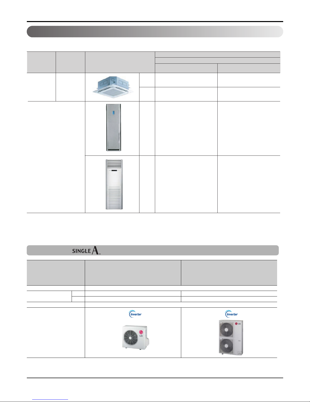
2. Model line up
2.1 Indoor units
2.2 Outdoor units
DC Inverter (1Ø)
DC Inverter
AUUW243D
[LUU245HV]
AUUW423D
[LUU425HV]
No. of connectable indoor units 1
Total capacity index of Btu/h 24,000 42,000
connectable indoor units kW 7.1 12.5
Power supply 1Ø, 208-230V, 60Hz
Chassis
24,000(7.1) 42,000(12.5)
ATNH243PLAD
[LCN245HV]
ATNH423MLAD
[LCN425HV]
APNH2433LAD
[LFN245HV]
APNH423TLAD
[LFN425HV]
Category Type
Model Name
Capacity, Btu/h(kW)
Chassis
4way
Ceiling
cassette
Floor Standing
TP
TM
P3
PT
* High Efficiency Indoor Units
- 7 -
Copyright ©2009 LG Electronics. Inc. All right reserved.
Only for training and service purposes
LGE Internal Use Only
Part 1 General Information
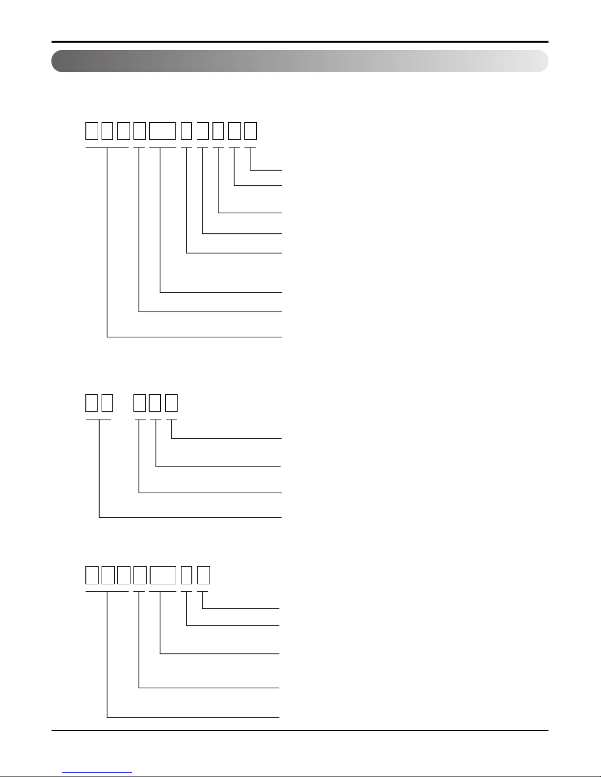
3. Nomenclature
• Global Model Name
3.1 Indoor unit s
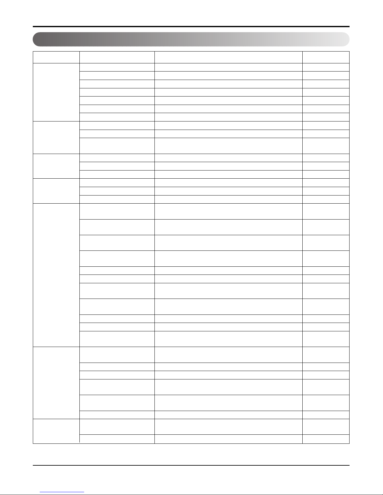
3.2 Decoration panel(For ceiling cassette models)
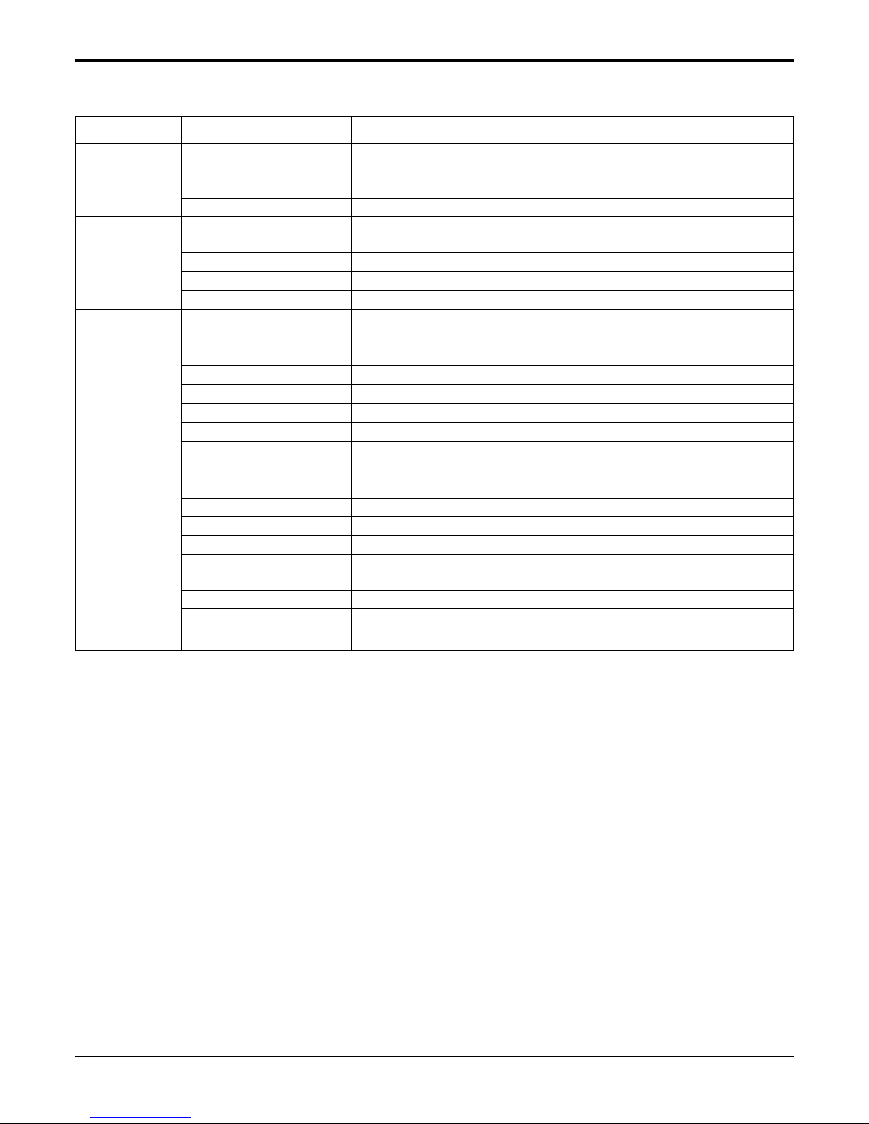
3.3 Outdoor units
A T NH 2 4 3 P L AD
Serial Number
Functions
A : Basic C : Plasma Air Purifier E: Elevation grille
Look : Basic
Chassis Name
Electrical Ratings
6:1
G: 1Ø 220V~240V, 50/60Hz
3: 1Ø 208V~230V, 60Hz
Ø,220V-240V,50Hz 8:3 Ø,380V-415V,50Hz
Capacity code
Model Type
C: Cooling Only H: Heat Pump
R410A Universal Indoor Unit
ATN : Universal Ceiling Cassette Type Indoor Unit
ABN : Universal Ceiling Concealed Duct Type Indoor Unit
AVN : Universal Ceiling & Floor Type Indoor Unit
A U UH 1 8 6A
Serial Number
Electric Standard (Phase, Volts, Freq)
6:1
3: 1Ø 208V~230V, 60Hz
Ø,220V-240V,50Hz 8:3 Ø ,380V-415V,50Hz
Capacity code
Model Type
C : Cooling Only H : Heat Pump W: Inverter Heat Pump
R410A Universal Outdoor Unit
PT- H E A
Functions
A: Basic C:For Indoor Unit with Plasma Air Purifier.
Indoor Unit Chassis
Model Type
C : Cooling Only H : Heat Pump U: Universal
Decoration Panel of Ceiling Cassette Type Indoor Unit

- 8 -
Copyright ©2009 LG Electronics. Inc. All right reserved.
Only for training and service purposes
LGE Internal Use Only
Part 2 Functions & Controls
Part 2 Functions & Controls
1. List of Functions & Controls ...........................................................................................9
2. Air flow ............................................................................................................................11
2.1 Auto swing (left & right) ...............................................................................................11
2.2 Auto swing (up & down) ..............................................................................................11
2.3 Chaos swing (up/down)...............................................................................................11
2.4 Air flow step.................................................................................................................12
2.5 Chaos wind (auto wind)...............................................................................................12
2.6 Jet Cool Mode Operation ............................................................................................12
2.7 Swirl wind Swing .........................................................................................................12
3. Air purifying ....................................................................................................................13
3.1 PLASMA Air Purifying System ....................................................................................13
4. Installation Functions ....................................................................................................16
4.1 Installer Setting -E.S.P.................................................................................................16
4.2 High Ceiling operation.................................................................................................17
5. Reliability ........................................................................................................................19
5.1 Hot start ......................................................................................................................19
5.2 Self-diagnosis Function...............................................................................................19
5.3 Soft dry operation........................................................................................................19
6. Convenience Functions & Controls .............................................................................20
6.1 Auto changeover operation ........................................................................................20
6.2 Child Lock Function.....................................................................................................24
6.3 Forced operation .........................................................................................................26
6.4 Timer(On/Off) ..............................................................................................................26
6.5 Two Thermistor Control ...............................................................................................27
6.6 Filter Sign clear ...........................................................................................................28
- 9 -
Copyright ©2009 LG Electronics. Inc. All right reserved.
Only for training and service purposes
LGE Internal Use Only
Part 2 Functions & Controls
1. List of Functions & Controls
Auto swing (left & right) Optional
Auto swing (up & down) Optional
Chaos swing (up & down) Optional
Airflow steps (fan/cool/heat)
Chaos wind (auto wind) Optional
Jet cool (Power wind)
Swirl wind Swing Optional
Deodorizing filter
Plasma air purifier Optional
Pre-filter
(washable/anti-fungus)
Drain pump Optional
E.S.P. control Optional
High ceiling operation Optional
Hot start
Self diagnosis
Soft dry operation
Auto changeover
Optional
Auto clean
Optional
Auto operation
(artificial intelligence)
Auto restart operation
Child lock Optional
Forced operation
Group control
Sleep mode
Timer (on/off)
Timer (weekly)
Two thermistor control
Optional
Standard wired remote
controller
Deluxe wired remote controller Optional
Simple wired remote controller
Wired remote Controller
(for hotel use)
Wireless remote controller
(simple)
Wireless LCD remote control Optional
General central controller
(Non LGAP)
Dry contact
Category Function Description Remark
Horizontal Airflow Direction control
Vertical Airflow Direction control
Vertical Airflow Direction control
Indoor Fan speed Control
Indoor Fan speed Control by chaos pattern
Powerful cooling mode
Distribute & stir the Air inside.
Air filtration using Deodorizing filter
Air filtration using plasma filter
Air filtration using pre-filter
Drain water pump
Changeable External Static Pressure
Function to Control the Air Volume by Ceiling Height
To prevent cold wind blow on heating mode start
Error code displays
Dehumidification
Cooling mode is automatically changed to heating mode and
vice verse
After cooling operation, this function makes the
evaporator dry
Air volume & set temp. are automatically selected for comfort
on Cooling/Heating mode
When power returns after a power failure, unit restarts in the
previous operating mode
Protect the unit operation without approval
Operation without remote controller
Where several products are linked, one specific control
device can control a specific number of products.
Air volume & set temp. are automatically changed for com-
fortable sleep
Operation by Timer setting
Operation by weekly reservation
Option to control temperature by referring thermistor in the
Indoor unit or the LCD wired remote.
Standard wired remote controller
Deluxe wired remote controller
Simple wired remote controller
Wired remote controller (for hotel use)
Wireless remote controller (simple)
Wireless LCD remote control
General central controller
Dry contact
Airflow
Installation
Air purifying
Reliability
Convenience
Individual control
CAC network
function
- 10 -
Copyright ©2009 LG Electronics. Inc. All right reserved.
Only for training and service purposes
LGE Internal Use Only
Part 2 Functions & Controls
Network Solution (LGAP)
PDI
(Power Distribution Indicator)
PI 485
Zone control
Low ambient operation
Space Control Optional
Auto Elevation Optional
Outdoor Normal
Comp. control
EEV control
FAN control
Oil Return Control
Oil equalizing
Sump Heating
Protection Control
Inverter protection
Defrost / Deicing
High pressure switch Optional
Low pressure switch
Phase protection
Restart delay
Optional
(3-minutes)
Self diagnosis
Soft start Optional
Test function
Category Function Description Remark
Network Solution (LGAP)
PDI (power distribution indicator)
Network control using PI 485 (Internet)
control the operation of the Air conditioning unit where each
zone
For operation at low temp.
Vanes angle can be controlled by pair.
Grille is automatically down to clean
Outdoor Control
Compressor Control
EEV Control
FAN control
Oil Return Control
Oil equalizing Control
Sump Heating Control
Protection Control
Inverter protection
Condenser frost prevention
Detect high pressure for safety
Detect low pressure for safety
Misconnection prevention for three phase
For overload prevention
Error code displays
Soft start for compressor
Test operation
CAC network
function
Special Function
& KIT
Other
Functions
& Controls
Notes: The Exploded View part has the particular Function table for each model.
- 11 -
Copyright ©2009 LG Electronics. Inc. All right reserved.
Only for training and service purposes
LGE Internal Use Only
Part 2 Functions & Controls
2. Air flow
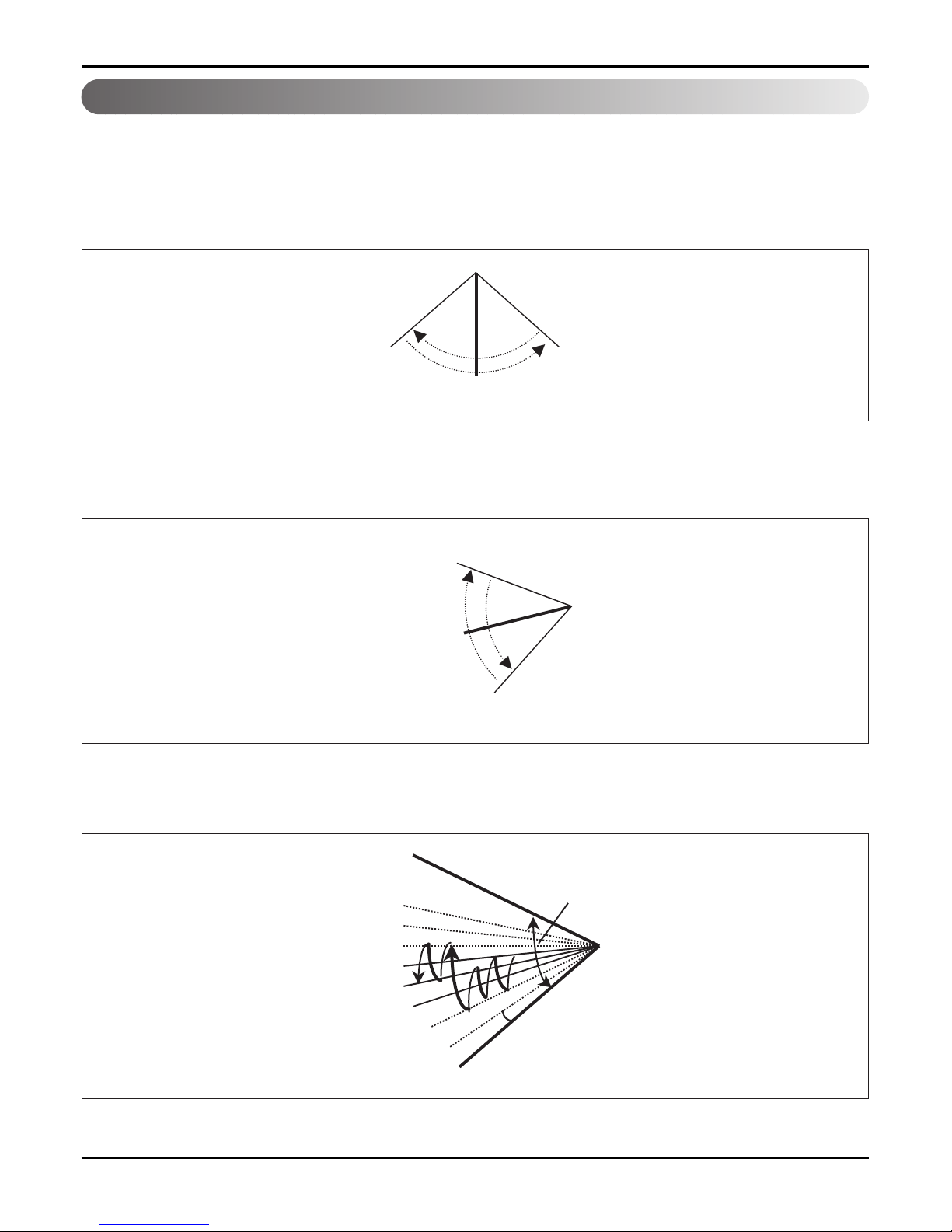
2.1 Auto swing (left & right)
RightLeft
110° ~ 120°
Open
Close
110° ~ 120°
Mode2
Mode3
Mode4
Mode5
Mode6
Mode7
Mode8
Mode9
OPEN
CLOSED
7~8°
110~120°
• By the horizontal airflow direction control key input, the left/right louver automatically operates with the auto swing or it
is fixed to the desired direction.
2.2 Auto swing (up & down)
• By the auto swing key input, the upper/lower vane automatically operates with the auto swing or it is fixed to the
desired direction.
2.3 Chaos swing (up/down)
• By the Chaos swing key input, the upper/lower vane automatically operates with the chaos swing or it is fixed to the
desired direction.
* Some Models are different with swing width and swing pattern.
NOTE: Some Models are different by swing width and swing pattern.
- 12 -
Copyright ©2009 LG Electronics. Inc. All right reserved.
Only for training and service purposes
LGE Internal Use Only
Part 2 Functions & Controls
2.4 Air flow step
• Indoor fan motor control have 6 steps.
• Air volume is controlled "SH", "H", "Med", Low" by remote controller.
• "LL" step is selected automatically in Hot start operation.
2.5 Chaos wind (auto wind)
• When "Auto" step selected and then operated, the high, medium, or low speed of the airflow mode is operated for
2~15 sec. randomly by the Chaos Simulation
2.6 Jet Cool Mode Operation
• While in heating mode or Fuzzy operation, the Jet Cool key cannot be input.
When it is input while in the other mode operation (cooling, dehumidification, ventilation), the Jet Cool mode is operated.
• In the Jet Cool mode, the indoor fan is operated at super-high speed for 30 min. at cooling mode operation.
• In the Jet Cool mode operation, the room temperature is controlled to the setting temperature, 18°C.
• When the sleep timer mode is input while in the Jet Cool mode operation, the Jet Cool mode has the priority.
• When the Jet Cool key is input, the upper/lower vanes are reset to those of the initial cooling mode and then operated
in order that the air outflow could reach further.
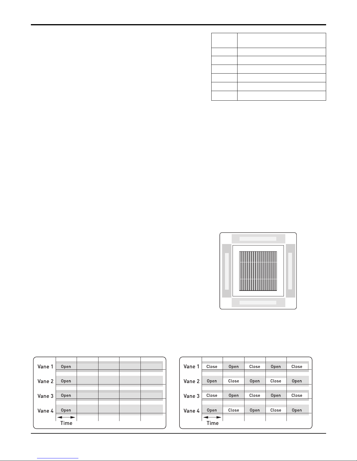
2.7 Swirl wind Swing
• It is the function for comfort cooling/heating operation.
• The diagonal two louvers are opened the more larger
than the other louvers. After one minute, it is opposite.
• Comparison of Air Flow Types
4-Open (conventional) Swirl Swing (New)
LL Very low, In heating mode
L Low
M Med
H High
SH Super high
Auto Chaos wind
Step Discription
Vane 4
Vane 2
Vane 1 Vane 3
- 13 -
Copyright ©2009 LG Electronics. Inc. All right reserved.
Only for training and service purposes
LGE Internal Use Only
Part 2 Functions & Controls
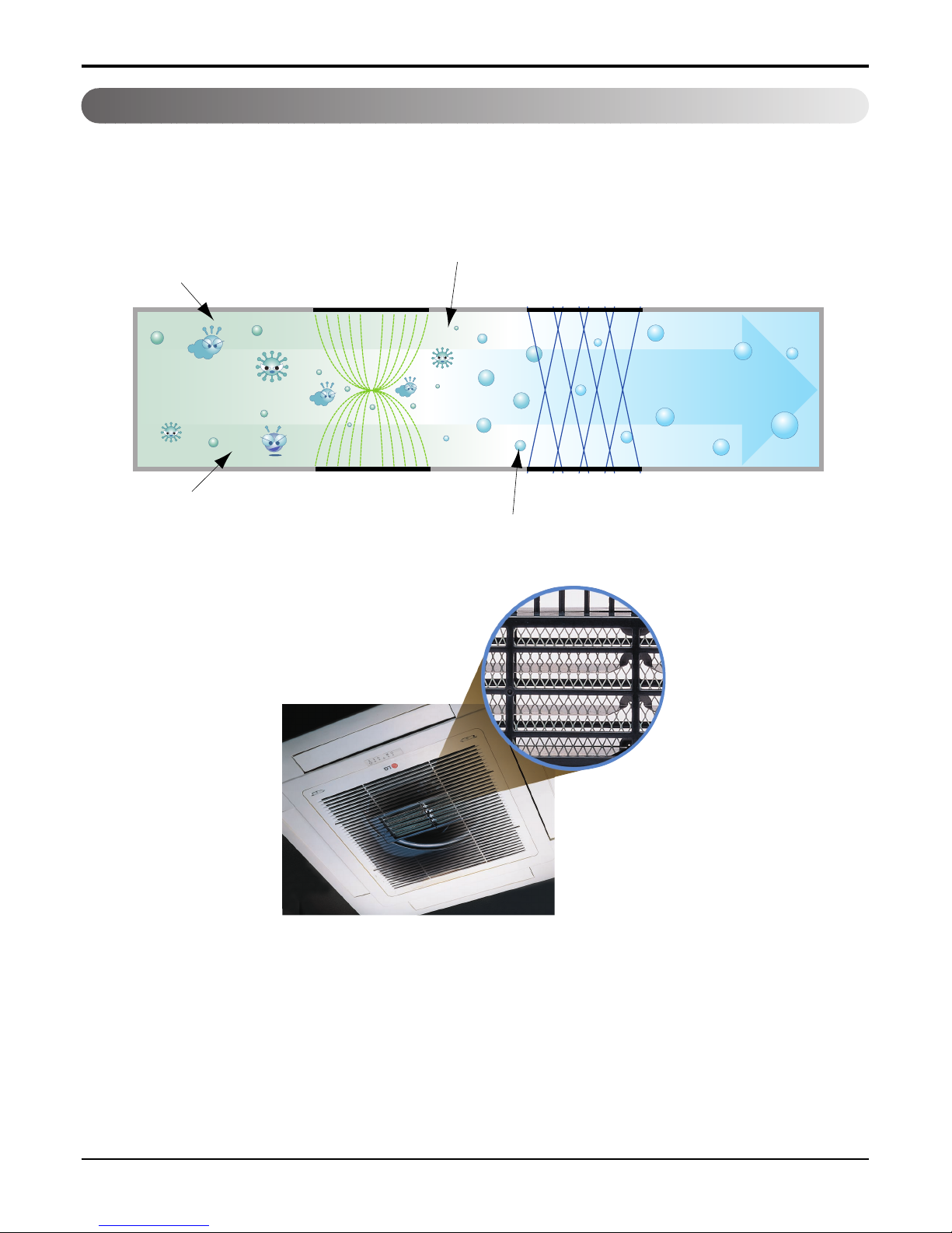
3.1 PLASMA Air Purifying System
The PLASMA Air Purifying System not only removes microscopic contaminants and dust, but also removes house
mites, pollen, and pet fur to help prevent allergic diseases like asthma. This filter that can be used over and over again
by simply washing with water.
3. Air purifying
Ionizer
Photo-Catalyst Coated Mesh
Dust particles
Odour
Dust electrode discharge
Odour molecule
Generating plasma
+
+
+
+
Polluted Air
Purified fresh Air
+4.8KV discharge
+
- 14 -
Copyright ©2009 LG Electronics. Inc. All right reserved.
Only for training and service purposes
LGE Internal Use Only
Part 2 Functions & Controls
- 15 -
Copyright ©2009 LG Electronics. Inc. All right reserved.
Only for training and service purposes
LGE Internal Use Only
- 16 -
Copyright ©2009 LG Electronics. Inc. All right reserved.
Only for training and service purposes
LGE Internal Use Only
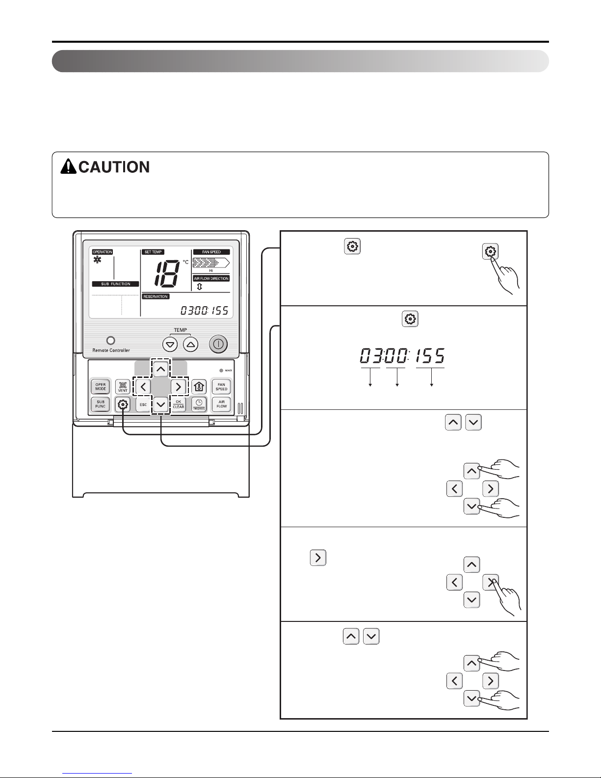
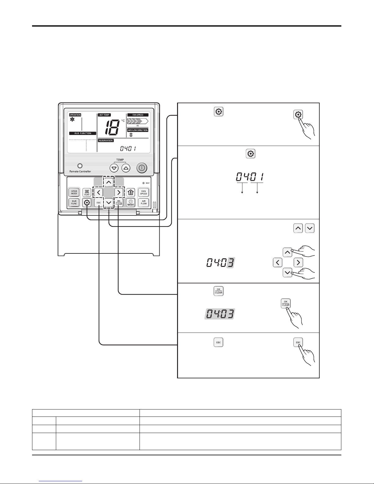
4.1 Installer Setting -E.S.P.
4. Installation Functions
Function Code ESP valueESP step
Press button for 4 seconds
to enter the installer setting
mode until timer segment
display “01:01”.
1
Repeat pressing button to select
Function code 03.
2
Set ESP step by pressing button.
(01: very low, 02: low, 03: medium, 04:
high. 05: power)
3
Move to ESP setting by pressing
button.
4
Press button to select ESP
value(0~255).
5
What is an E.S.P function?
This is the function that decides the strength of the wind for each wind level and because this function is to make the installation
easier, please do not use this function when using the remote controller.
If you set ESP incorrectly, the air conditioner may malfunction.
This setting must be carried out by a certificated-technician.
This function is used for only Duct product.
- 17 -
Copyright ©2009 LG Electronics. Inc. All right reserved.
Only for training and service purposes
LGE Internal Use Only
Part 2 Functions & Controls
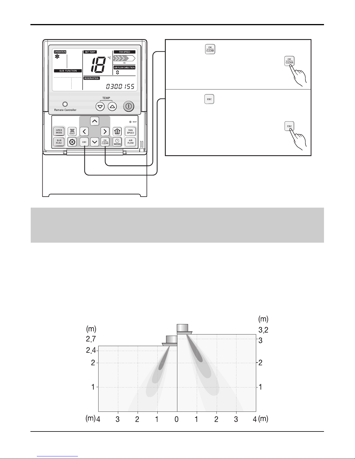
Press button to save or release.
6
Press button to exit or the system
will automatically exit after 25 seconds
without any input.
7
❊ Weak and Power setting is not available for some products.
❊ Because the ESP value is already appropriately set when manufactured from the factory, it is recommended that you do
not change the ESP value.
4.2 High Ceiling operation
Function to Control the Air Volume by Ceiling Height Control of the air intensity has been made possible by employing a
height-control algorithm for the interior fan.
According to the height of the installation, it provides variability of indoor fan motor rpm. If the height of installation is low
then you can adjust low rpm of indoor fan motor. On the other hand if the height of the installation is high you can adjust
high rpm of indoor fan motor. Selection of speed can be done by slide switch at the back of the LCD wired remote.
Installation on the
normal-height ceiling
installation on the
higher ceiling
- 18 -
Copyright ©2009 LG Electronics. Inc. All right reserved.
Only for training and service purposes
LGE Internal Use Only
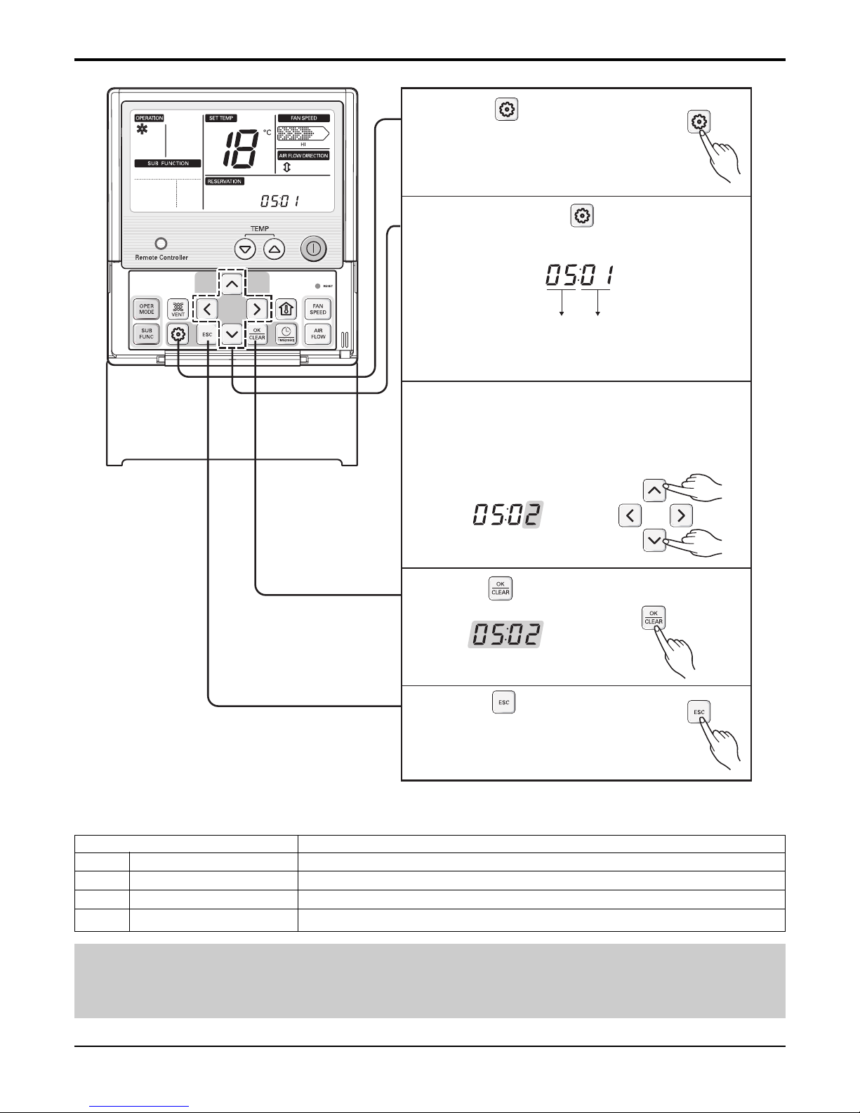
Function Code Ceiling height
Press button for 4 seconds
to enter the installer setting
mode until timer segment
display “01:01”.
1
Repeat pressing button to select
Function code 05.
Ex) Setting Ceiling Height as 'Standard'.
2
Select ceiling height value by pressing
button.
(01:Low, 02:Standard, 03:High,
04:Super high)
3
Press button to save or release.
4
Press button to exit or
system will automatically exit
after 25 seconds without any
input.
5
❊ Ceiling height setting is available only for some products.
❊ Ceiling height of ‘Super high’ function may not exist depending on the indoor unit.
❊ Refer to the product manual for more details.
Ceiling Height Level Description
01 Low Decrease the indoor airflow rate 1 step from standard level
02 Standard Set the indoor airflow rate as standard level
03 High Increase indoor airflow rate 1 step from standard level
04 Super high Increase indoor airflow rate 2 steps from standard level
<Ceiling Height Selection Table>
Part 2 Functions & Controls
- 19 -
Copyright ©2009 LG Electronics. Inc. All right reserved.
Only for training and service purposes
LGE Internal Use Only
Part 2 Functions & Controls
5.1 Hot start
• When heating is started, the indoor fan is stopped or very slow to prevent the cold air carry out
• When the temp. of heat exchanger reach 30°C(model by model), indoor fan is started.
5.2 Self-diagnosis Function
• The air conditioner installed can self-diagnosed its error status and then transmits the result to the central control.
Therefore, a rapid countermeasure against failure of the air conditioner allows easy management and increases the
usage life of air conditioner.
• Refer to trouble shooting guide.
5.3 Soft dry operation
• When the dehumidification operation input by the remote control is received, the intake air temperature is detected and
the setting temp is automatically set according to the intake air temperature.
• While compressor off, the indoor fan repeats low airflow speed and stop.
• While the intake air temp is between compressor on temp. and compressor off temp., 10-min dehumidification opera-
tion and 4-min compressor off repeat.
Compressor ON Temp. ➔ Setting Temp+0.5°C
Compressor OFF Temp. ➔ Setting Temp-0.5°C
• The indoor fan speed is automatically set to the low, so the shift of the indoor fan speed is impossible because of
already being set to the best speed for Dry Operation by Micom Control.
5. Reliability
Intake air Temp. Setting Temp.
26°C ≤ intake air temp. 25°C
24°C ≤ intake air temp.< 26°C intake air temp. -1°C
22°C ≤ intake air temp. < 24°C intake air temp. -0.5°C
18°C ≤ intake air temp. < 22°C intake air temp.
intake air temp. < 18°C18°C
- 20 -
Copyright ©2009 LG Electronics. Inc. All right reserved.
Only for training and service purposes
LGE Internal Use Only
Part 2 Functions & Controls
6. Convenience Functions & Controls
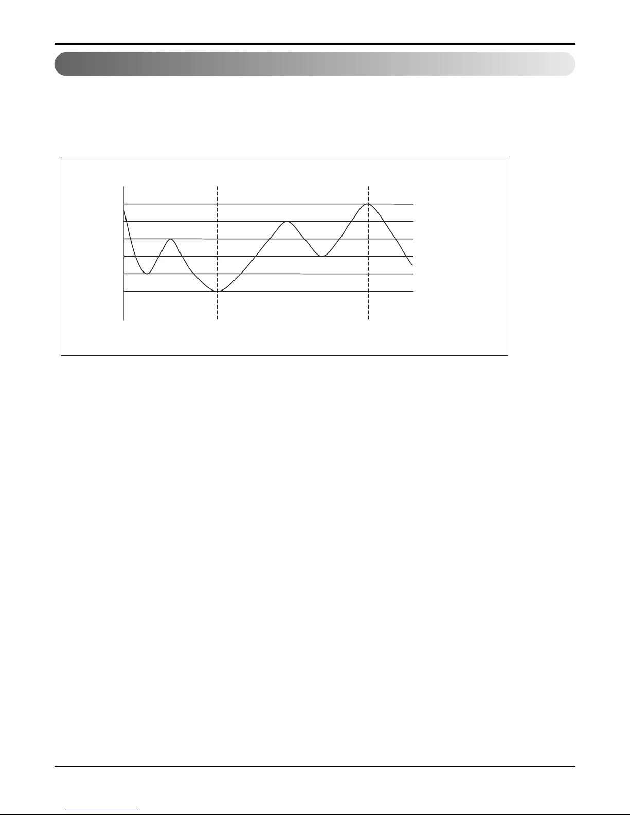
6.1 Auto changeover operation
• The air conditioner changes the operation mode automatically to keep indoor temperature.
• When room temperature vary over ±2°C with respect to setting temperature, air conditioner keeps the room tempera-
ture in ±2°C with respect to setting temperature by auto change mode.
SET Temp.
+0.5°C
-0.5°C
-2°C
+4°C
+2°C
Cooling
operation
Heating operation Cooling
operation
Cooling thermo off
Heating thermo off
Switching point
Switching point
- 21 -
Copyright ©2009 LG Electronics. Inc. All right reserved.
Only for training and service purposes
LGE Internal Use Only
Part 2 Functions & Controls
■ Cooling & heating Opeattions
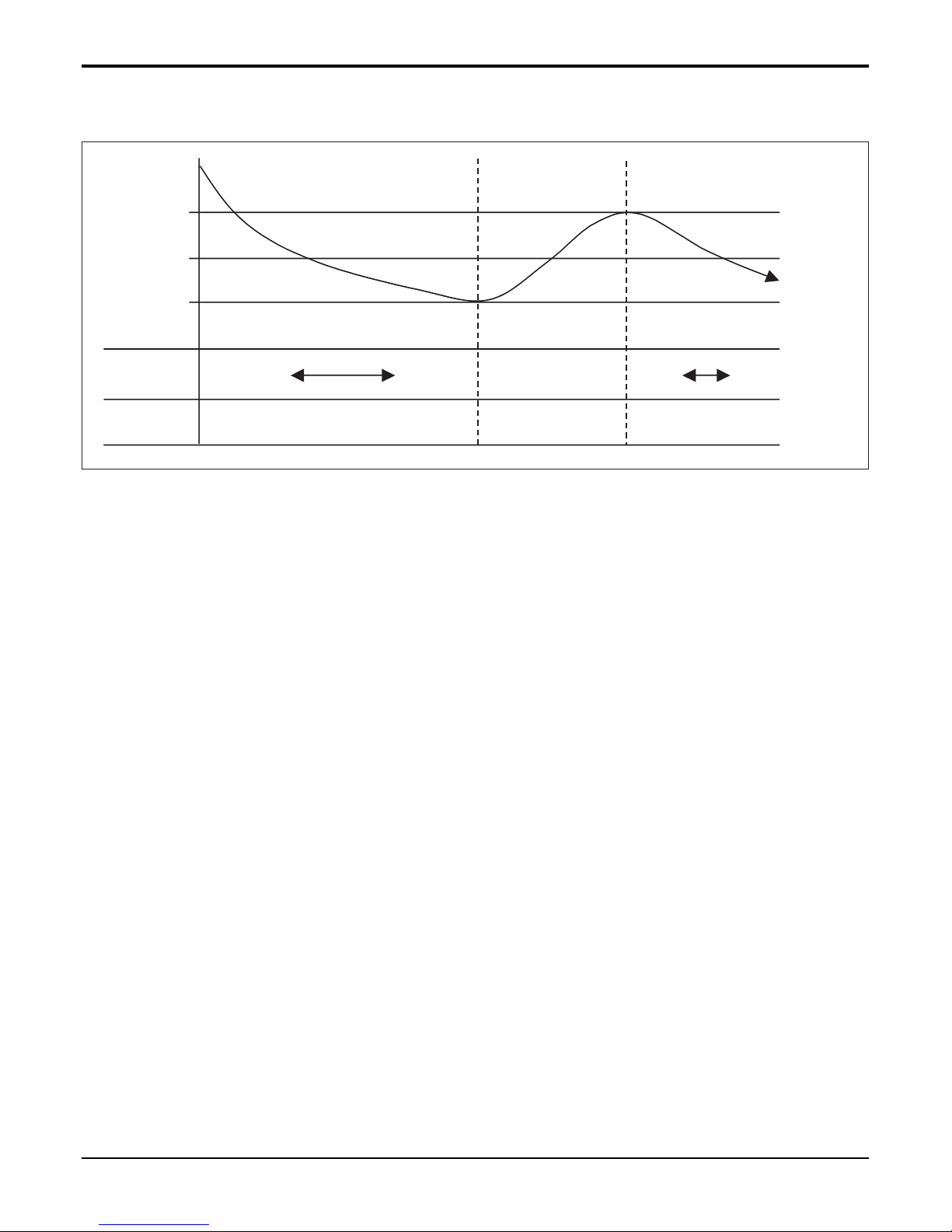
6.1.1 Cooling Mode
Setting
Temp.
-0.5°C.
+0.5°C.
Comp. OFF
Comp. ON Comp. OFF Comp. ON
INV. Comp.
Frequency
Constant
Comp.
Low
High Low
Thermo.
ON
Thermo
OFF
High
• Operating frequency of compressor depends on the load condition, like the difference between the room temp. and the
set temp., frequency restrictions.
• If the compressor operates at some frequency, the operating frequency of compressor cannot be changed within 30
seconds. ( not emergency conditions)
• Compressor turned off when
- intake air temperature is in between ±0.5°C of the setting temp. limit for three minutes continuously.
- intake air temperature reaches below 1.0°C of the temperature of setting temp..
• Compressors 3 minutes time delay.
- After compressor off, the compressor can restart minimum 3 minutes later.
- Compressor operating range is form 40% to 110% of rated condition.
- 22 -
Copyright ©2009 LG Electronics. Inc. All right reserved.
Only for training and service purposes
LGE Internal Use Only
Part 2 Functions & Controls
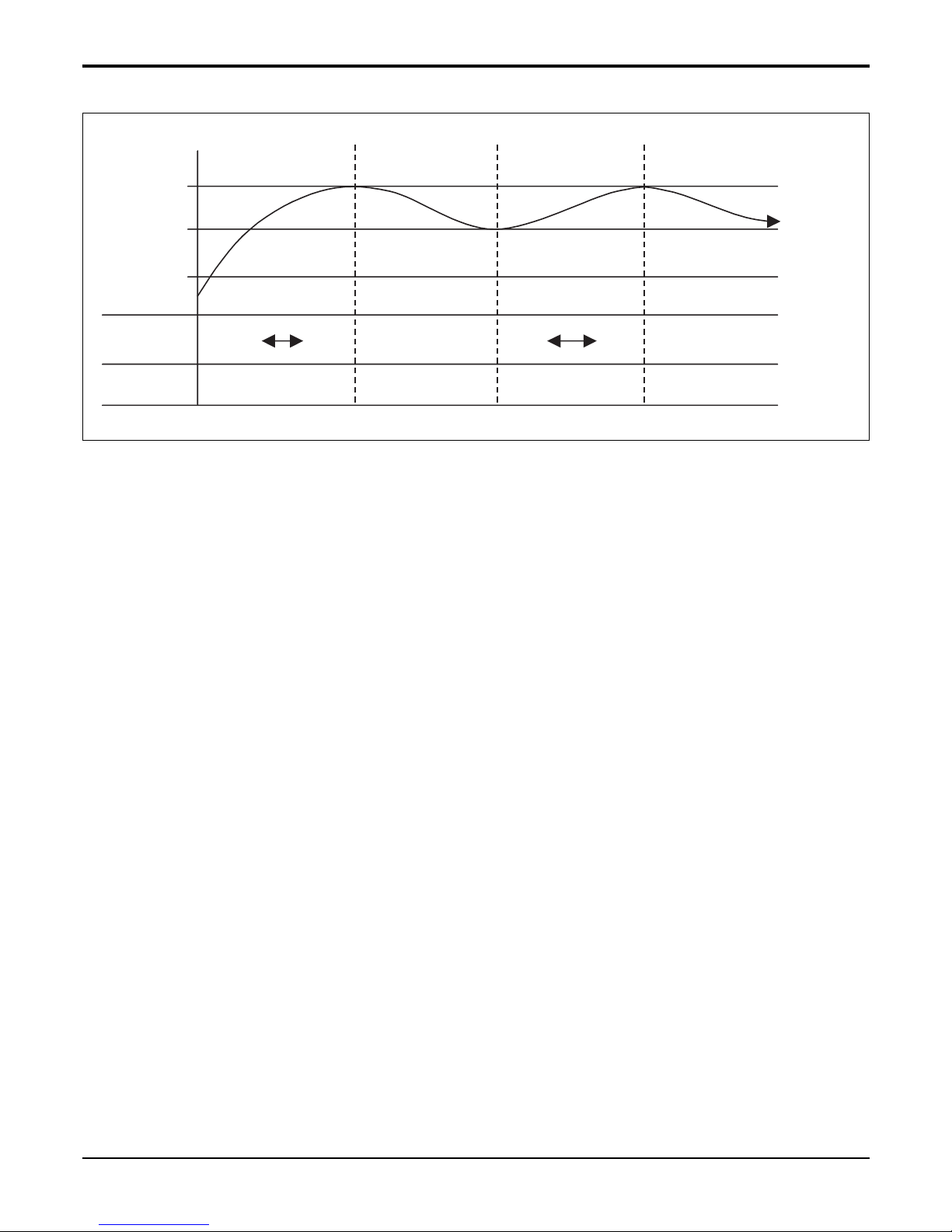
6.1.2 Heating Mode
+2°C.
+4°C.
Comp. OFF
Comp. ON Comp. OFF Comp. ON Comp. OFF
INV. Comp.
Frequency
Constant
Comp.
Low
High LowHigh Comp. OFF
Thermo
ON
Thermo
OFF
Setting
Temp.
• Operating frequency of compressor depend on the load condition, The difference between the room temp. and set
temp., frequency restrictions.
• If compressor operates at some frequency, the operating frequency of compressor cannot be changed within 30 sec-
onds.
• Condition of compressor turned off
- When intake air temperature reaches +4°C above the setting temperature.
• Condition of compressor turned on
- When intake air temperature reaches +2°C above the setting temperature.
* Condition of indoor fan turned off
- While in compressor on : indoor pipe temp. < 20°C (Option)
- While in compressor off : indoor pipe temp. < 30°C (Option)
• While in defrost control, between the indoor and outdoor fans are turned off.
• Compressor 3 minutes delay
- After compressor off, the compressor can restart minimum 3 minutes later.
NOTE: Some Models are different by temperature of thermo ON/OFF.
- 23 -
Copyright ©2009 LG Electronics. Inc. All right reserved.
Only for training and service purposes
LGE Internal Use Only
Part 2 Functions & Controls
* Some Models are different with temperature of indoor fan ON/OFF
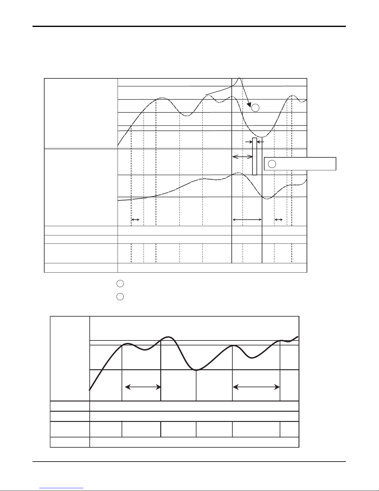
■ Heating Mode Operation Details
The unit will operate according to the setting by the remote controller and the operation diagram is shown as following.
COMP
Outdoor fan
Indoor fan
4way valve
Setting Temperature
+2°C
(Thermo ON)
Setting Temperature
+4°C
(Thermo OFF)
Indoor unit
Heat-Exchanger
temperature
1min
Minimum
3min
1min
3min
Setting
fan
speed
Setting
fan
speed
Setting
fan
speed
ON
ON
ON
ON
Low
LowLowLow
Low
Lo
OffOffOff
ON
OFF
OFF
Low fan during 10sec
A
A
B
B
Intake Air Temperature
• Compressor-off interval : - While the indoor Heat-Exchanger temperature is higher than 27°C, fan operates
at low speed, when it becomes lower than 26°C fan stops.
- For eleminating latent heat-loss, fan operates at low speed for 10 seconds periodically.
(Option)36°C
(Option)34°C
(Option)29°C
(Option)27°C
(Option)16°C
ON
ON
Off Off
Low
Low
1min1min
(Option)
20°C
(Option)
27°C
(Option)
33°C
Indoor unit
Heat-Exchanger
temperature
Setting fan
speed
Setting fan
spped
Compressor
Outdoor fan
Indoor fan
4way Valve
ON
SET
FAN
ROOM
SET
FAN
ROOM
FAN
SPEED
ON
OFF
MODE
SET
FAN
ROOM
SET
FAN
ROOM
FAN
SPEED
ON
OFF
MODE
- 24 -
Copyright ©2009 LG Electronics. Inc. All right reserved.
Only for training and service purposes
LGE Internal Use Only
Part 2 Functions & Controls
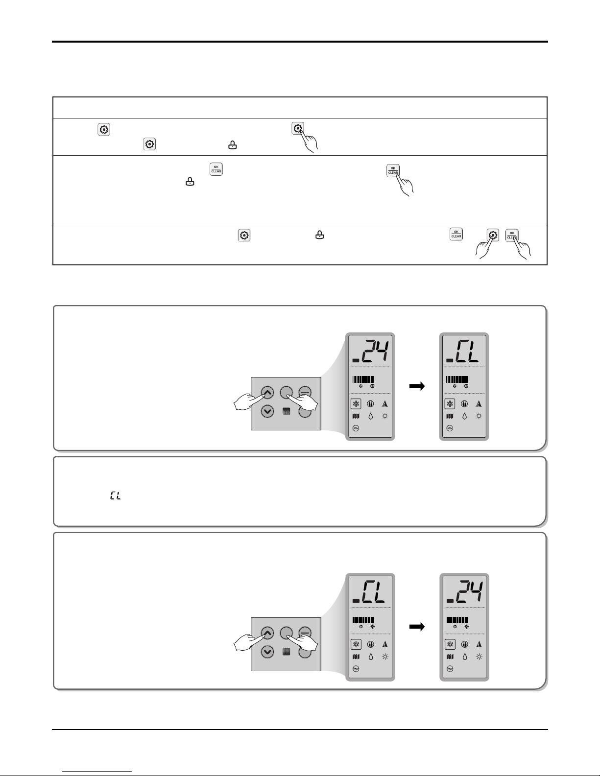
6.2 Child Lock Function
This function is to prevent children or other people from using indoor.
• Press button.
• Repeat pressing button until the icon flash.
• When the button flashing, press button to set this function.
• When setting this function, icon
will be displayed whenever entering any operation except for Room
temperature access. However, it is possible to control normally by
wireless remote controller.
To release this setting, keep pressing button until icon flash and then enter
button.
Touched the fan speed and high temperature setting keys simultaneously
for 3 seconds.
The display key will be locked with beep after 3 seconds.
1
During Child Lock Operation
➊ Whenever you Touch any key on Display panel, it will immediately display
“ ”, which means Display panel is Locked.
❷ All the key on the indoor unit Display panel will not work.
❸ But the key on the remote controller will work.
2
For releasing child lock Operation
Press the fan speed and high temperature setting keys simultaneously for 3 seconds again.
The unit will respond with beep, Child Lock Operation will removed.
3
1. Ceiling cassette type
2-1. Floor Standing type_P3
Part 2 Functions & Controls
- 25 -
Copyright ©2009 LG Electronics. Inc. All right reserved.
Only for training and service purposes
LGE Internal Use Only
Auto restart
In case the power comes on again after a power failure, Auto Restarting Operation is the function to operate procedures automatically to the previous operating conditions.
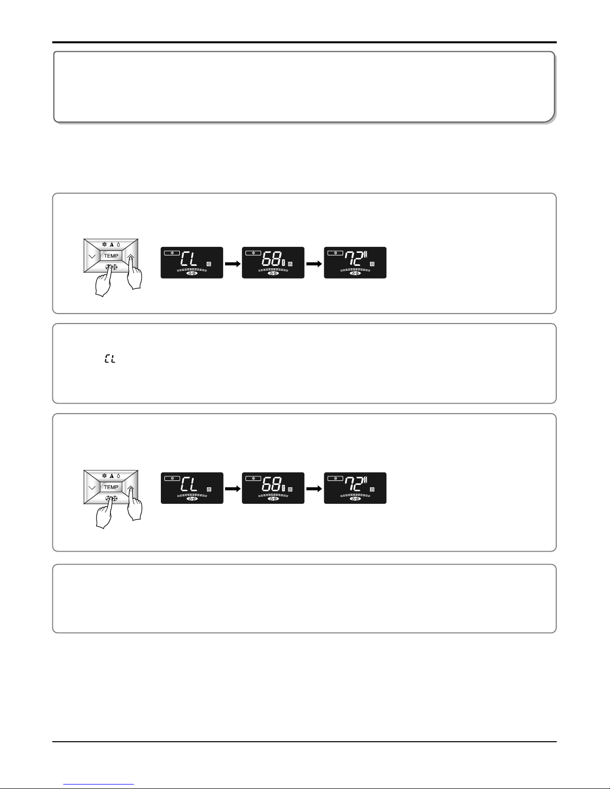
2-2. Floor Standing type_PT
Press the fan speed button and High temperature setting buttons simultaneously for 3 seconds.
The unit will respond with beep.
1
2
3
After 3 second,
it will shift
After 3 seconds,
it will shift
After pressing
the buttons
it will shift
immediately
After 3 seconds,
it will shift
During Child Lock Operation
➊ Whenever you press any Button, it will immediately display
“ ”, which means Button is Locked.
❷ All the Button on the indoor unit will not work.
❸ But the Button on the remote controller will work.
For releasing child lock Operation
Press the fan speed button and High temperature setting buttons simultaneously for 3 seconds.
The unit will respond with beep, Child Lock Operation will removed.
Auto restart
In case the power comes on again after a power failure, Auto Restarting Operation is the function to operate procedures automatically to the previous operating conditions.
6.4 Sleep Timer Operation
• When the sleep time is reached after <1,2,3,4,5,6,7,0(cancel) hr> is input by the remote control while in appliance
operation, the operation of the appliance stops.
• While the appliance is on pause, the sleep timer mode cannot be input.
• While in cooling mode operation, 30 min later since the start of the sleep timer, the setting temperature increases by
1°C. After another 30 min elapse, it increases by 1°C again.
• When the sleep timer mode is input while in cooling cycle mode, the airflow speed of the indoor fan is set to the low.
• When the sleep timer mode is input while in heating cycle mode, the airflow speed of the indoor fan is set to the medi-
um.
6.5 Timer(On/Off)
6.5.1 On-Timer Operation
• When the set time is reached after the time is input by the remote control, the appliance starts to operate.
• The timer LED is on when the on-timer is input. It is off when the time set by the timer is reached.
• If the appliance is operating at the time set by the timer, the operation continues.
While in Fuzzy operation, the airflow speed of the indoor fan is automatically selected according to the temperature.
6.5.2 Off-Timer Operation
• When the set time is reached after the time is input by the remote control, the appliance stops operating.
• The timer LED is on when the off-timer is input. It is off when the time set by the timer is reached.
• If the appliance is on pause at the time set by the timer, the pause continues.
Part 2 Functions & Controls
- 26 -
Copyright ©2009 LG Electronics. Inc. All right reserved.
Only for training and service purposes
LGE Internal Use Only
6.3 Forced operation
• To operate the appliance by force in case when the remote control is lost, the forced operation selection switch is on
the main unit of the appliance, and operate the appliance in the standard conditions.
• The operating condition is set according to the outdoor temp. and intake air temperature as follows.
• The unit select the last operation mode in 3 hours.
• Operating procedures when the remote control can't be used is as follows :
- The operation will be started if the ON/OFF button is pressed.
- If you want to stop operation, re-press the button.
Indoor temp.
over 24°C
21~24°C
below 21°C
Setting temp.
22°C
22°C
22°C
Setting speed of
indoor fan
High speed
Operating Mode
Cooling
Healthy Dehumidification
Heating
- 27 -
Copyright ©2009 LG Electronics. Inc. All right reserved.
Only for training and service purposes
LGE Internal Use Only
Part 2 Functions & Controls
6.6 Two Thermistor Control
There may be a significant difference between temperature taken at the installed product indoor temperature. Two thermistor control provides option to control temperature by referring any of the two temperatures.
With help of the slide switch at the back of the wired remote controller, selection of the thermistor for controlling the unit
can be One thermistor is in the Indoor unit & the one is in the LCD wired remote.
■ Two Thermistor System
Function Code Thermistor setting
Press button for 4 seconds
to enter the installer setting
mode until timer segment
display “01:01”.
1
Set Thermistor mode by pressing
button. (01: Remote Controller,
02: Indoor, 03: 2TH)
3
Press button to save or release.
4
Press button to exit or
system will automatically exit
after 25 seconds without any
input.
5
Repeat pressing button to select
Function code 04.
Ex) Setting Thermistor as '2TH'.
2
❊ Therefore system will use value that sensed from indoor unit or remote controller
<Thermistor Table>
Temperature sensor location Function
01 Remote controller Operation in remote controller Temperature sensor
02 Indoor unit Operation in indoor unit temperature sensor
03 2-Thermistor(2TH)
Operation in lower temperature after comparing the temperature between the indoor
unit and remote controller
 Loading...