

LG ATNH246FLFB, ATNH186ELFB, ATNH486DLFB, AVNH126ELAB, ATNH606DLFB Service Manual
...
LG
Synchro
Air Conditioner
SERVICE MANUAL
LG
CAUTION
website http://www.lgservice.com
e-mail http://www.lgeservice.com/techsup.html
• BEFORE SERVICING THE UNIT, READ THE SAFETY
PRECAUTIONS IN THIS MANUAL.
• ONLY FOR AUTHORIZED SERVICE PERSONNEL.

2 Synchro Air Conditioner
Synchro Air Conditioner Service Manual
TABLE OF CONTENTS
Model Number Nomenclature......................................................................3
Safety Precautions .......................................................................................4
Model Names...............................................................................................11
External Appearance ..................................................................................12
Dimensions .................................................................................................13
Product Specifications...............................................................................22
Combination table ......................................................................................27
Installation...................................................................................................28
Operation ....................................................................................................63
Control Devices and Function...................................................................78
Schematic Diagram ....................................................................................91
Piping Diagrams .......................................................................................105
Troubleshooting Guide.............................................................................112
(3-way) Valve ............................................................................................133
Exploded View & Replacement Parts List ..............................................137
Service Manual 3
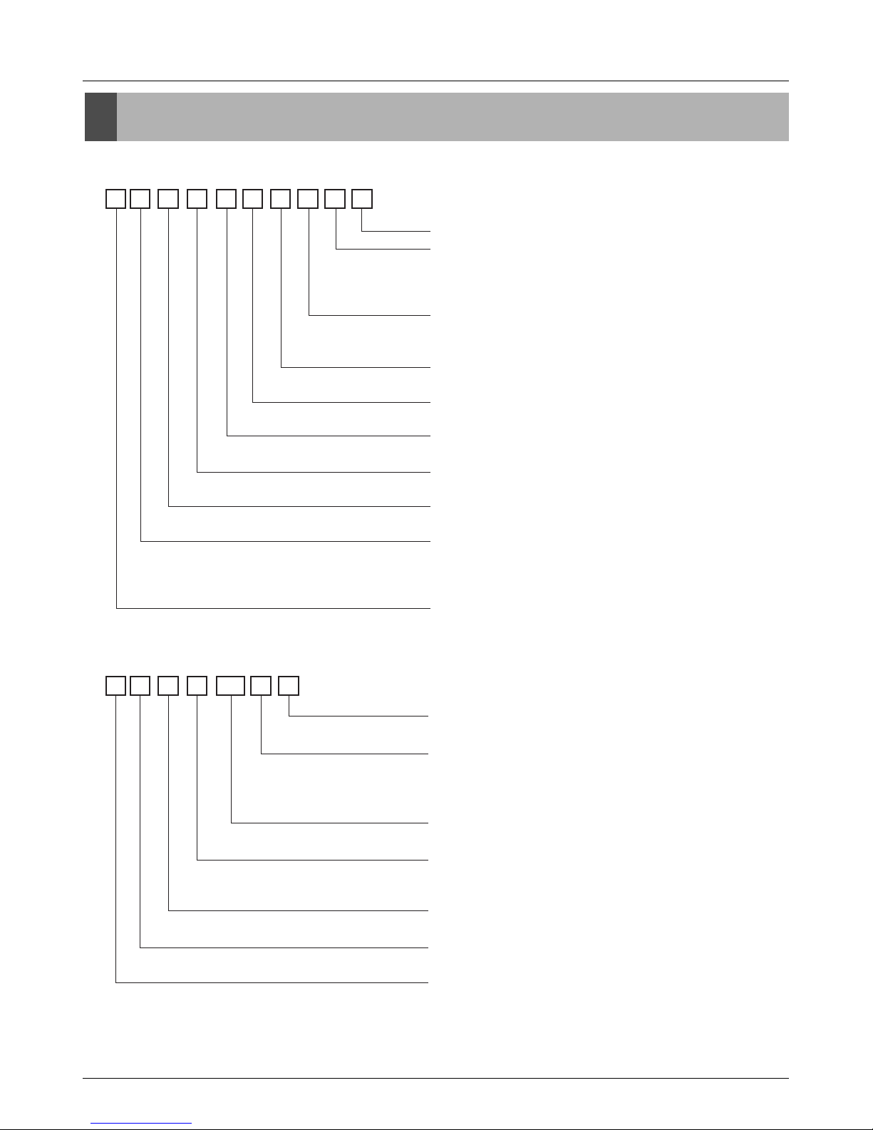
Model Number Nomenclature
Model Number Nomenclature
Indoor Unit
Outdoor Unit
A T N H 18 6 E L F B
Serial Number
Function
A : Basic
E : E/Grille
F : Plasma + Elevation grille
Panel type
Cassette L : Basic panel, W : Wooden panel
Duct : L
Chassis type
Cassette : E/F/D, Convertible : E/B, Duct : H/G/R
Electrical Rating
6 : 1Ø 220-240V ,50Hz
Nominal Cooling Capacity in Btu/h
Ex)18,000Btu/h '18', 24,000Btu/h '24'
Model Type
H : Heat Pump
Unit Type
N : Indoor Unit U : Outdoor Unit
Indoor Unit Type
T : Ceiling Cassette
V : Ceiling&Floor(Convertible)
B : Ceiling Concealed Duct
Refrigerent Type
A : R410A, L : R22
A U U H 100 8 0
Air Discharge Type
0 : Top discharge, A : Side discharge
Electrical Rating(Volt/Hertz/Phase)
1 : 115 / 60 / 1 2 : 220 / 60 / 1
3 : 208-230 / 60 / 1 5 : 200-220 / 50 / 1
6 : 220-240 / 50 / 1 8 : 380-415 / 50 / 3
Nominal Cooling Capacity in Btu/h
Ex)72,000Btu/h '72', 100,000Btu/h '100'
Model Type
W : DC Inverter Heat Pump(MPS Inverter)
H : Conventional Heat Pump(MPS Variable)
Unit Type
N : Indoor Unit, U : Outdoor Unit
Indoor Unit Type
2/3/4 : Multi Room, U : Universal, B : Duct, T : Cassette
Refrigerent Type
A : R410A, L : R22

Service Manual 11
Model Names
Model Names
Indoor Unit
Outdoor Unit
Branch Kit
TE
Ceiling Cassette 4-Way TF
TD
Ceiling & Floor(Convertible)
VE
VB
BH
Ceiling Concealed Duct BG
BR
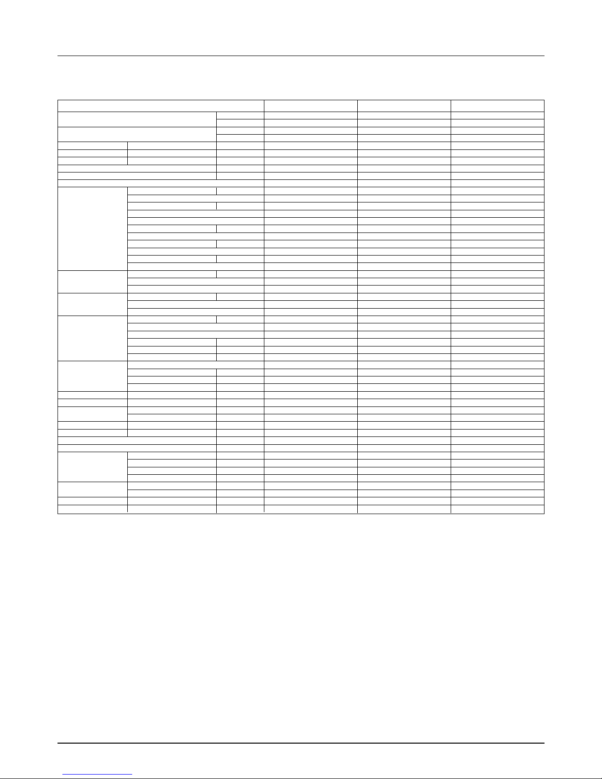
Model Name
Nominal Capacity[Btu/h(Kw)]
Chassis
Name
Type
12,000
(3.5)
18,000
(5.3)
24,000
(7.0)
30,000
(8.8)
36,000
(10.6)
48,000
(14.1)
60,000
(17.6)
ATNH126ELFB ATNH186ELFB - - - -
- - ATNH246FLFB ATNH306FLFB - -
- - - - ATNH366DLFB ATNH486DLFB ATNH606DLFB
AVNH126ELAB - - - - -
- AVNH186BLAB AVNH246BLAB AVNH306BLAB - -
- ABNH186HLAB ABNH246HLAB - - -
- - - ABNH306GLAB ABNH366GLAB -
- - - - - ABNH486RLAB ABNH606RLAB
Indoor Unit
MPS Inverter UY AUUW4860 AUUW6060 - -
UH AUUH488B - - -
MPS Variable UY - - AUUH 7280 -
UW - - - AUUH10080
Model Name
Nominal Capacity[Btu/h(Kw)]
Type
Chassis
Name
48,000
(14.0)
60,000
(17.6)
72,000
(21.1)
100,000
(29.0)
Outdoor Unit
Name of accessory
Model No. Indoor classification Capacity Ratio(%) Remark
PMUB11A
"Synchro" Duo
50:50(1:1)
PMUB23A 40:60(2:3) Unbalance type
Branch Kit
PMUB111A 33:33:33(1:1:1)
PMUB112A "Synchro" Trio 25:25:50(1:1:2) Unbalance type
PMUB122A 20:40:40(1:2:2) Unbalance type
PMUB1111A "Synchro" Quartet 25:25:25:25(1:1:1:1)
12 Synchro Air Conditioner
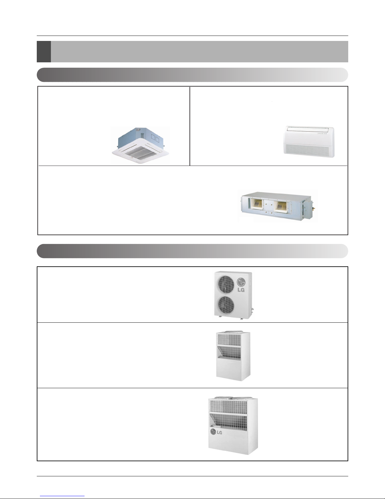
External Appearance
External Appearance
Indoor Unit
Outdoor Unit
Ceiling Cassette-4Way Ceiling & Floor(Convertible)
Ceiling Concealed Duct
ATNH126ELFB / ATNH186ELFB
ATNH246FLFB / ATNH306FLFB
ATNH366DLFB / ATNH486DLFB
ATNH606DLFB
AVNH126ELAB / AVNH186BLAB
AVNH246BLAB / AVNH306BLAB
ABNH186HLAB / ABNH246BHLAB
ABNH306GLAB / ABNH366BGLAB
ABNH486RLAB / ABNH606RLAB
AUUW4860 / AUUW6060
AUUH7280
AUUH488B
AUUH10080
Service Manual 13
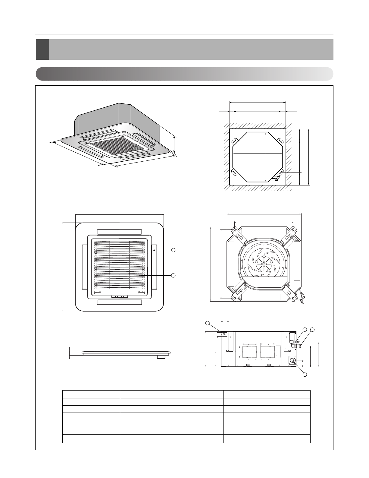
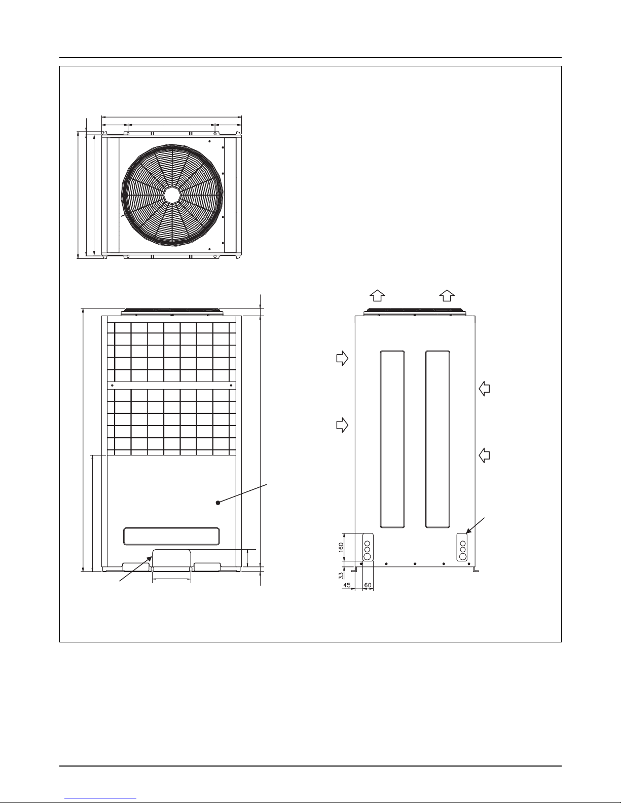
Dimensions
Dimensions
Indoor Unit
CLOSE OPEN OPEN CLOSE
269
670
30
570
269
190.5
160
52
90
90
120.4
30
521
670
570
450
40
110 110
670
670
4
132
5
6
Unit:mm
570 Unit size
570 Unit size
450 (Hanging bolt)
7575
600 (Ceiling opening)
600 (Ceiling opening)
521(Hanging bolt)
39.5
39.5
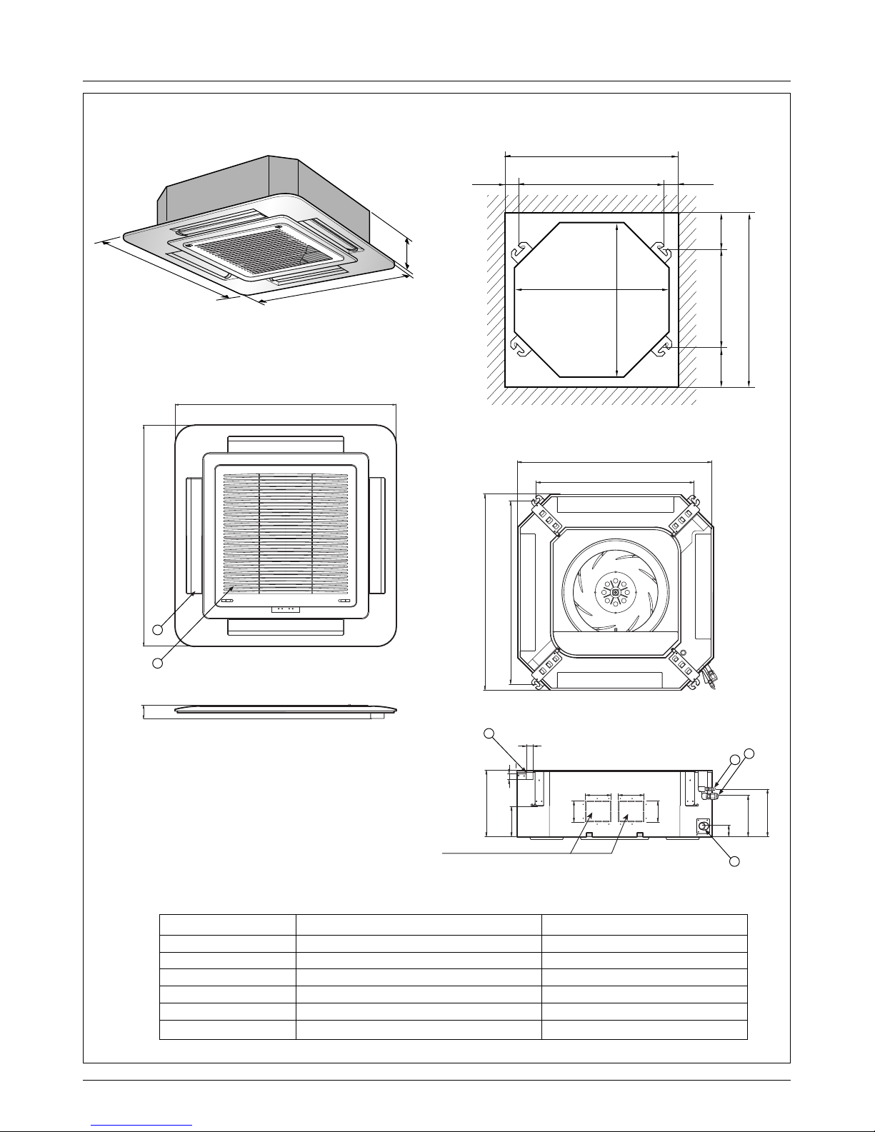
1. Cassette Type - TE(12K/18K)
(unit : mm)
Number Name Descripition
1 Liquid pipe connection ø6.35 flare
2 Gas pipe connection
12k: ø9.52, 18k: ø12.7 flare
3 Drain pipe connection
4 Power supply connection
5 Air discharge grill
6 Air suction grill
14 Synchro Air Conditioner
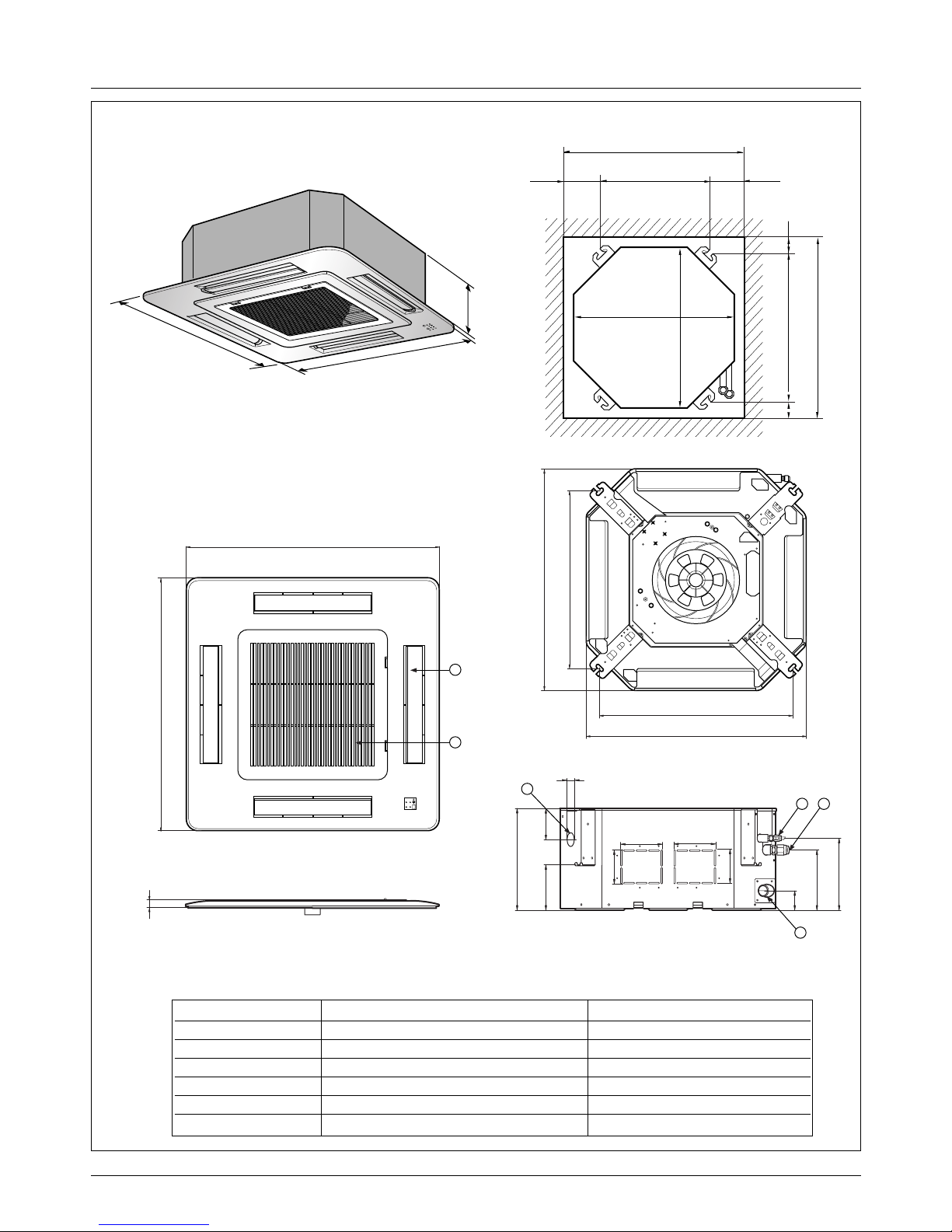
Dimensions
2. Cassette Type - TF (24K/30K)
292
850
850
850
850
744
658
572
744
292
212
150
54
90
90
192 117
70
110 110
4
132
5
6
Unit:mm
744 Unit size
744 Unit size
658 (Hanging bolt)
6666
790 (Ceiling opening)
790 (Ceiling opening)
572(Hanging bolt)
109
109
30
(unit : mm)
Number Name Descripition
1 Liquid pipe connection ø6.35 flare
2 Gas pipe connection
24K: ø12.7, 30K: ø15.88 flare
3 Drain pipe connection
4 Power supply connection
5 Air discharge grill
6 Air suction grill
Service Manual 15
Dimensions
288
950
950
950
950
290
210.5
180
52
140
40
110
30
90
90
110
55
840
785
840
678
Fresh Air Inlet
Unit:mm
840 Unit size
840 Unit size
672 (Hanging bolt)
101.5101.5
875 (Ceiling opening)
875 (Ceiling opening)
785 (Hanging bolt)
45
45
4
5
6
1
3
2
(unit : mm)
Number Name Descripition
1 Liquid pipe connection
36K: ø6.35, 48K/60K: ø9.52 flare
2 Gas pipe connection
36K: ø15.88, 48K/60K: ø19.05 flare
3 Drain pipe connection
4 Power supply connection
5 Air discharge grill
6 Air suction grill
3. Cassette Type - TD(36K/48K/60K)
16 Synchro Air Conditioner
Dimensions
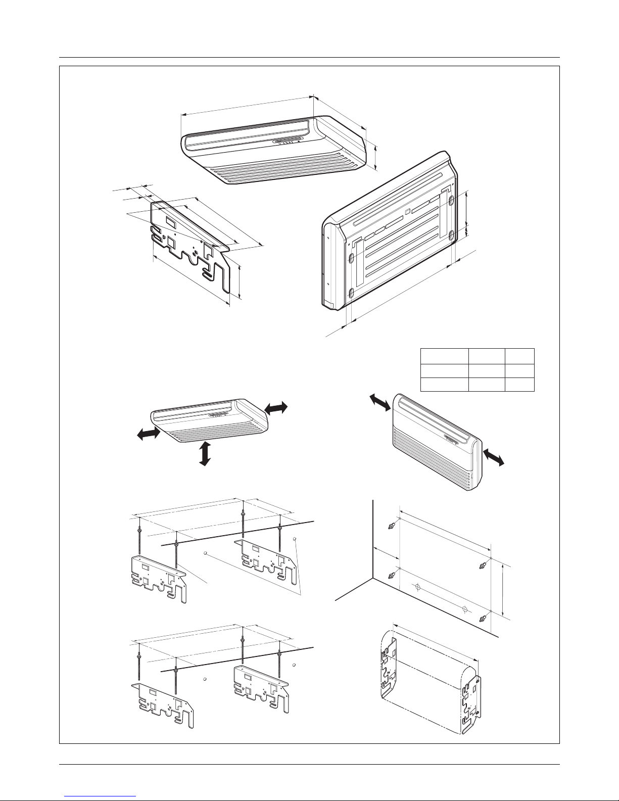
Ø 12.7Ø 6.3518k, 24k
Ø 15.88Ø 6.3530k
GasLiquidModel
1. Pipe Specification(mm)
Note:
1200
205
615
R
More than
20cm
More than eye-level
More than
20cm
R
(Ceiling installation)
R
More than
20cm
More than
20cm
(Floor/Wall installation)
(Rear Side)
(Unit: mm)
1076
Suspension bolt
(W3/8 or M10)
Center-line for the
piping hole
265
1236
265
1076
more than
260
265
1236
392
265
468
63
Ø10 Stud Bolt hole
38
175
(Installation Plate)
250
128
36
36
1
076
4. Ceiling & Floor(Convertible) - VB(18K/24K), VE(12K)
Service Manual 17
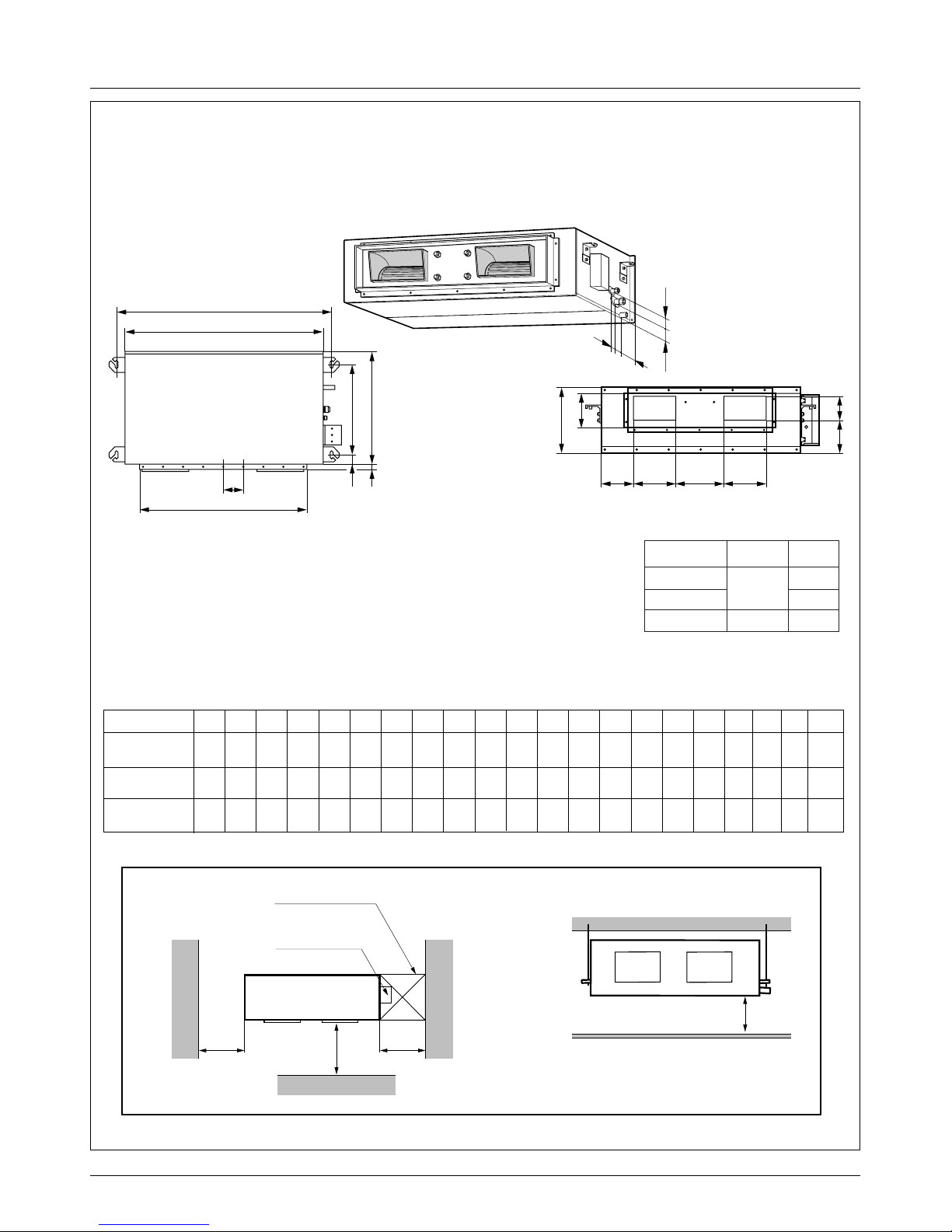
Dimensions
Top view
(unit: mm)
Front view
600600
Front
Inspection hole
※Suitable dimension "H" is necessary
to get a slope to drain as figure.
(600X600)
Control box
1000
H
l
i
h
j
k
A
H
CD
EF
B
(G)
ab c d
K
J
fe
Ø 12.7
Ø 15.88
Ø 6.35
Ø 9.52
18, 24k
30, 36
Ø 19.05
48, 60k
k
GasLiquidModel
1. Pipe Specification(mm)
Note:
C D E F (G) H J K a b c d e f h i j k l
355 45.5 450 30 87 750 163 260 61.5 243 212.3 243 110 130 52 66 81 30 158.5
355 45.5 450 30 87 830 186 298 229.5 243 232 243 116 160 53 59 81 19 158.5
477 56 590 30 120 1006 294 380 215 279 241 279 185 168 51 98 83 17 172
Capacity A B
932 882
1232 1182
1282 1230
ABNH186HLAB
ABNH246HLAB
ABNH306GLAB
ABNH366GLAB
ABNH486RLAB
ABNH606RLAB
(Unit: mm)
5. Ceiling Concealed Duct - BH(18K/24K), BG(30K/36K), BR(48K/60K)

18 Synchro Air Conditioner
Dimensions
AUUW48/6060
Air
inlet
Air
inlet
Air outlet
Service Panel
(Unit : mm)
Knockout hole
(For the control wiring,
the power supply,
refrigerant connecting
pipe)
Knockout hole
(For the control wiring, the power supply,
refrigerant connecting pipe)
153
15
690
144463
100
220
1507
670
730
153
806
500(bolt hole)
700(bolt hole)
Outdoor Unit
Service Manual 19
Dimensions
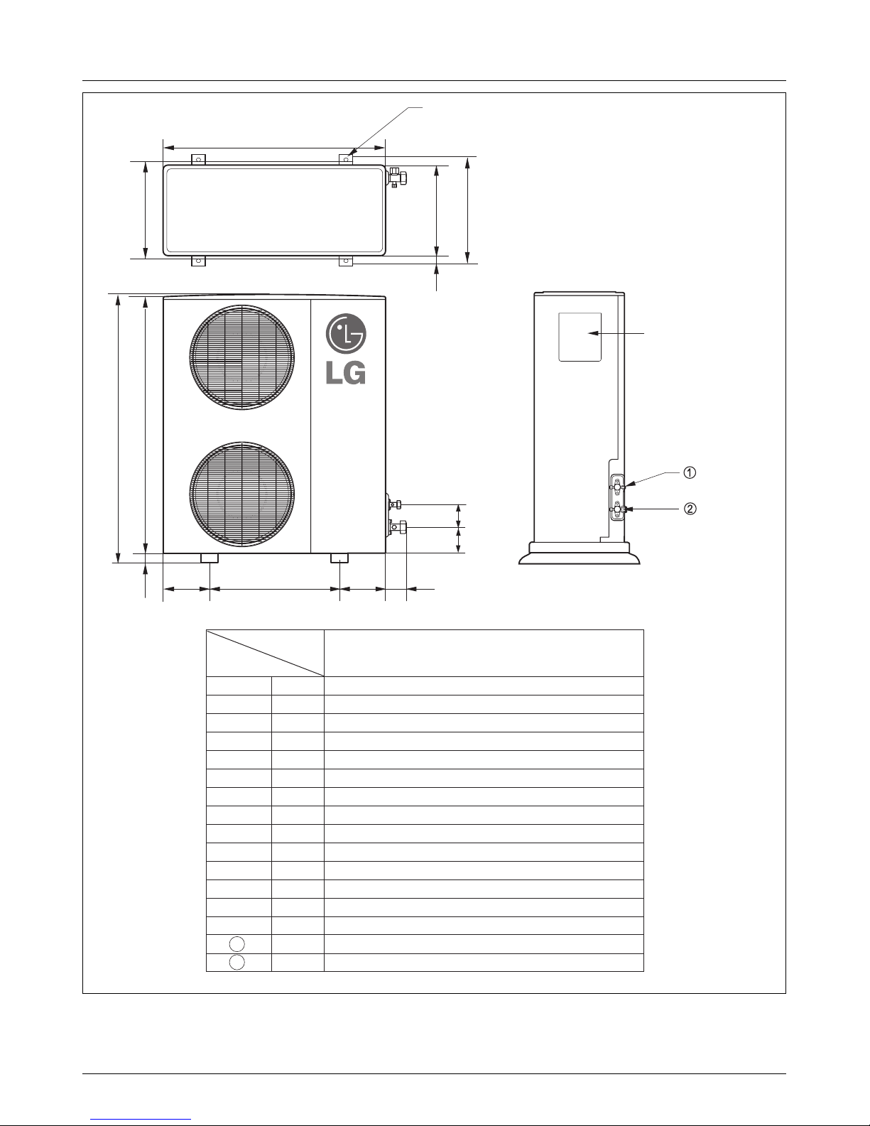
AUUH488B
L6L7 L8 L9
L4
H
L11
L10
L5
W
D
L1
L2
L3
Gas side
3-way valve
Control cover
Liquid side
3-way valve
4-hole for anchor bolts
Wmm 900
Hmm 1
,165
Dmm
370
L1 mm
460
L2 mm
45
L3 mm
410
L4 mm
1,135
L5 mm
30
L6 mm
550
L7 mm
175
L8 mm
175
L9 mm
112
L10 mm
120
L11
1
2
mm
83
mm Ø9.52
mm Ø19.05
AUUH488B
Model
Dimensions
20 Synchro Air Conditioner
Dimensions
AUUH7280
Air
inlet
Air
inlet
Air outlet
Service Panel
(Unit : mm)
Knockout hole
(For the control wiring,
the power supply,
refrigerant connecting
pipe)
Knockout hole
(For the control wiring, the power supply,
refrigerant connecting pipe)
153
15
690
40
144428
100
220
1512
670
730
153
806
500(bolt hole)
700(bolt hole)

Service Manual 21
Dimensions
45
33 160
60
15
190 900(bolt hole)
1280
190
700(bolt hole)
730
690
670
1555
63 1444
48
100
Air
inlet
Air
inlet
Air outlet
Service Panel
Knockout hole
Knockout hole
(For the control wiring, the power supply,
refrigerant connecting pipe)
(For the control wiring,
the power supply,
refrigerant connecting
pipe)
AUUH10080
22 Synchro Air Conditioner
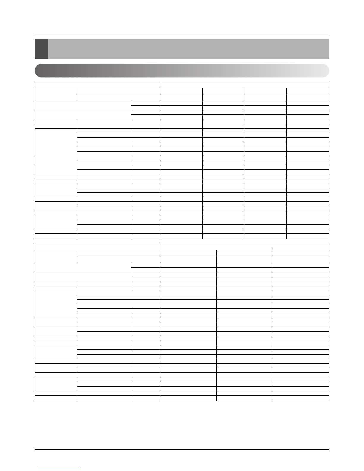
Product Specifications
3024(3517) 4536(5275) 6048(7033) 7056(8205)
12000 18000 24000 28000
3478(4044) 5116(5949) 6955(8089) 8114(9437)
13800 20300 27600 32200
9.5/8/7(336/283/247) 13/12/11(459/424/388) 15/14/13(523/494/459) 19/17/15(671/600/550)
18~30/16~30 18~30/16~30 18~30/16~30 18~30/16~30
18.3 22.4 40.3 48.6
IC-9630LGAE IC-9630LGAC OBM-3502P2 OBM-4105P2
6666
75 90 121 146
0.35 0.75 0.53 0.67
2.5/440 2.5/440 4/440 4/440
Turbo Fan Turbo Fan Turbo Fan Turbo Fan
1/13.0(330) 1/13.0(330) 1/15.0(382) 1/15.0(382)
670/620/550 720/670/620 600/540/480 650/600/550
670/620/550 720/670/620 600/540/480 650/600/550
38 / 35 / 32 41 / 39 / 37 43 / 41 / 39 45 / 42 / 39
Thermistor Thermistor Thermistor Thermistor
0.275(7.0) 0.275(7.0) 0.275(7.0) 0.275(7.0)
19 19 21 21
2R11C 2R11C 2R12C 2R12C
1.2 2.4 3 3.3
22.4*10.5*22.4 (570*269*570) 22.4*10.5*22.4 (570*269*570) 29.3*11.5*29.3 (744*292*744) 29.3*11.5*29. (744*292*744)
26.4*1.2*26.4 (670*30*670) 26.4*1.2*26.4 (670*30*670) 33.5*1.2*33.5 (850*30*850) 33.5*1.2*33.5 (850*30*850)
19(41.9) 19(41.9) 24(52.9) 24(52.9)
1/4(6.35) 1/4(6.35) 1/4(6.35) 1/4(6.35)
3/8(9.52) 1/2(12.7) 1/2(12.7) 5/8(15.88)
1.26(32) 1.26(32) 1.26(32) 1.26(32)
25.2*13.0*25.2 (640*330*640) 25.2*13.0*25.2 (640*330*640) 32.6*14.4*32.6 (828*365*828) 32.6*14.4*32.6 (828*365*828)
189/378 189/378 84/168 84/168
Rated Cooling Capacity kcal/hr(W)
Btu/hr
Ratedl Heating Capacity kcal/hr(W)
Btu/hr
Air Circulation Indoor(H/M/L)
CMM(CFM)
Setting temperature range °C
Fan motor Output W
Model
No. of Poles
Input W
Running Current A
Capacitor µF/Vac
Fan Type
No. Used / Diameter EA/inch(mm)
Fan RPM Cooling(H/M/L) rpm
Heating(H/M/L) rpm
Noise Level
(Sound Press,1m)
H/M/L dBA
Temperature controller
Coil Tube Size (OD) inch(mm)
Fins per inch
No. of Rows & Column
Dehumidification Rate l/h
Dimensions (W*H*D) Indoor inch(mm)
Panel inch(mm)
Net Weight kg(lbs)
Piping Liquid inch(mm)
Connection Gas inch(mm)
Drain hose (ID Ø)mm
Packing Dimension (W*H*D) inch(mm)
Stuffing Quantity
Without(Without) S/Parts 20/40ft
Ceiling Cassette - 4way
ATNH126ELFB
PT-HEC(F)
ATNH186ELFB
PT-HEC(F)
ATNH246FLFB
PT-HFC(F)
ATNH306FLFB
PT-HFC(F)
Indoor Unit Type
Model Indoor unit
Decoration panel
9072(10549) 12095(14067) 14112(16412)
36000 48000 56000
10433(12130) 13305(15474) 15523(18053)
41400 52800 61600
25/23/21(883/812/742) 30/28/26(1059/988/918) 34/32/30(1200/1130/1059)
18~30/16~30 18~30/16~30 18~30/16~30
52.5 58.5 107
IC-1630LGPJ IC-1640LGPH IC-14640LGPM
66 6
175 195 237
0.76 1.5 1.8
4/440 6/400 6/400
Turbo Fan Turbo Fan Turbo Fan
1/18.1(460) 1/18.1(460) 1/18.1(460)
550/510/470 600/555/520 700/650/600
550/510/470 600/555/520 700/650/600
40 / 38 / 36 43 / 41 / 39 50 / 47 / 43
Thermistor Thermistor Thermistor
0.275(7.0) 0.275(7.0) 0.275(7.0)
21 21 21
2R 12C 2R 12C 2R 12C
4 5.5 6.5
33.1*11.3*33.1 (840*288*840) 33.1*11.3*33.1 (840*288*840) 33.1*11.3*33.1 (840*288*840)
37.4*1.2*37.4 (950*30*950) 37.4*1.2*37.4 (950*30*950) 37.4*1.2*37.4 (950*30*950)
32(70.4) 32(70.4) 32(70.4)
1/4(6.35) 3/8(9.52) 3/8(9.52)
5/8(15.88) 3/4(19.05) 3/4(19.05)
1.26(32) 1.26(32) 1.26(32)
36.4*13.8*36.4 (925*350*925) 36.4*13.8*36.4 (925*350*925) 36.4*13.8*36.4 (925*350*925)
72/144 72/144 72/144
Rated Cooling Capacity kcal/hr(W)
Btu/hr
Ratedl Heating Capacity kcal/hr(W)
Btu/hr
Air Circulation Indoor(H/M/L)
CMM(CFM)
Setting temperature range °C
Fan motor Output W
Model
No. of Poles
Input W
Running Current A
Capacitor µF/Vac
Fan Type
No. Used / Diameter EA/inch(mm)
Fan RPM Cooling(H/M/L) rpm
Heating(H/M/L) rpm
Noise Level
(Sound Press,1m)
H/M/L dBA
Temperature controller
Coil Tube Size (OD) inch(mm)
Fins per inch
No. of Rows & Column
Dehumidification Rate l/h
Dimensions (W*H*D) Indoor inch(mm)
Panel inch(mm)
Net Weight kg(lbs)
Piping Liquid inch(mm)
Connection Gas inch(mm)
Drain hose (ID Ø)mm
Packing Dimension (W*H*D) inch(mm)
Stuffing Quantity
Without(Without) S/Parts 20/40ft
Ceiling Cassette - 4way
ATNH366DLFB
PT-HDC(F)
ATNH486DLFB
PT-HDC(F)
ATNH606DLFB
PT-HDC(F)
Indoor Unit Type
Model Indoor unit
Decoration panel
Product Specifications
Indoor Unit
Notes:
1. Capacities are based on the following conditions:
Cooling : - Indoor Temperature 27˚C(80.6˚F) DB / 19˚C(66.2˚F) WB
- Outdoor Temperature 35˚C(95˚F) DB / 24˚C(75.2˚F) WB
- Interconnecting Piping Length 7.5m
- Level Difference of Zero.
Heating : - Indoor Temperature 20˚C(68˚F) DB / 15˚C(59˚F) WB
- Outdoor Temperature 7˚C(44.6˚F) DB / 6˚C(42.8˚F) WB
- Interconnecting Piping Length 7.5m
- Level Difference of Zero.
2. Capacities are Net Capacities.
3. Due to our policy of innovation some specifications may be changed without notification.
Service Manual 23
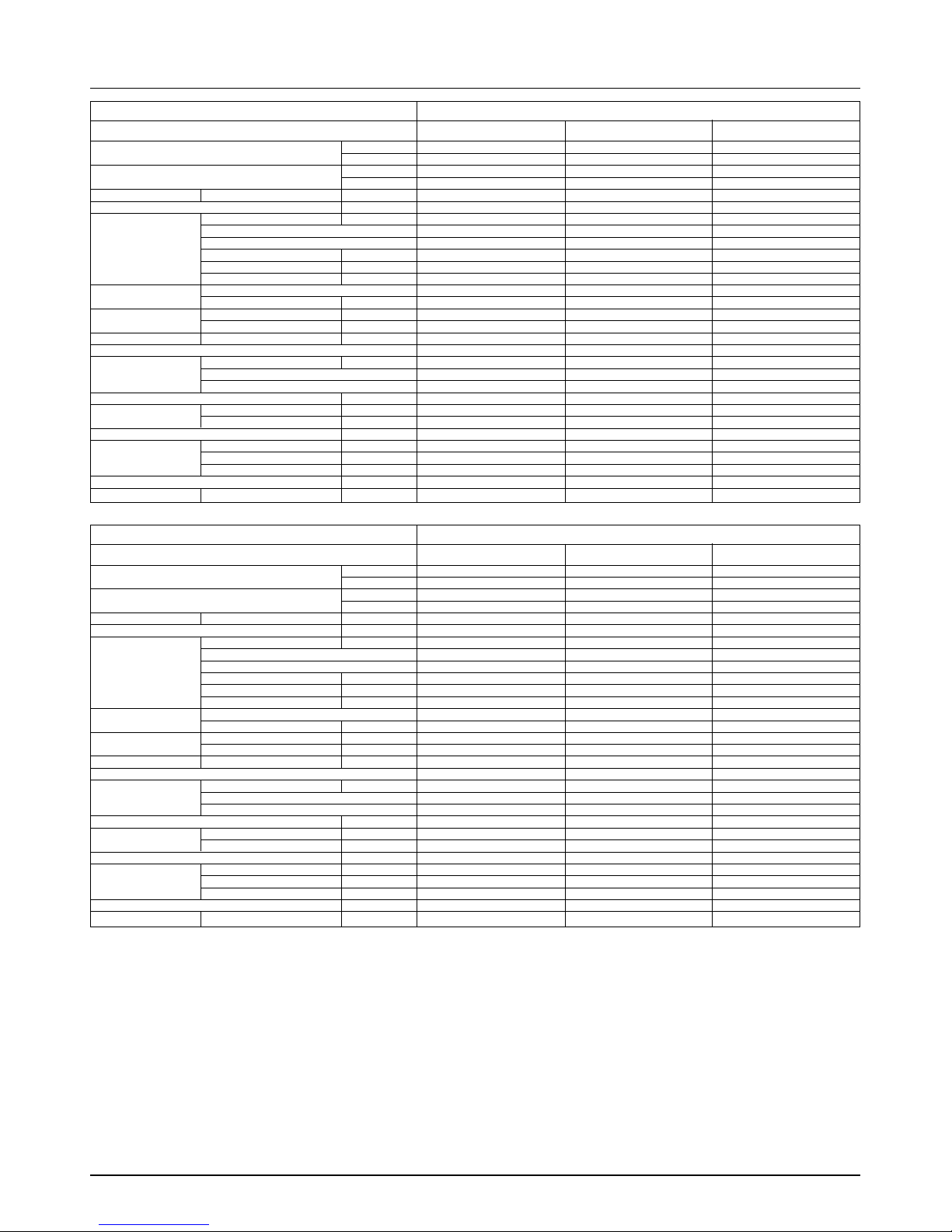
Product Specifications
4536(5275) 6048(7034) 7560(8791)
18000 24000 30000
5116(5949) 6955(8089) 8694(10110)
20300 27600 34500
16.5/14.5/13(583/512/459) 18/16.5/14(636/583/494) 26.5/23/20(936/812/706)
8810
18~30/16~30 18~30/16~30 18~30/16~30
118 118 211
IC-13450LG13C IC-13450LG13C IC-13450LG13J
44 4
180 180 300
0.92 0.92 1.34
6/370 6/370 6/370
Sirocco Fan Sirocco Fan Sirocco Fan
2/6.97(177) 2/6.97(177) 2/6.97(177)
1350/1310/1270 1410/1350/1250 1415/1360/1290
1350/1310/1270 1410/1350/1250 1415/1360/1290
36 / 34 /32 38 / 36 /34 40 / 38 /35
Thermistor Thermistor Thermistor
0.275(7.0) 0.275(7.0) 0.275(7.0)
21 21 21
2R 10C 3R 10C 3R 12C
2 2.5 3.3
34.6*10.2*17.7 (880*260*450) 34.6*10.2*17.7 (880*260*450) 46.5*11.7*17.7 (1180*298*450)
35(77.2) 35(77.2) 38(84)
1/4(6.35) 1/4(6.35) 1/4(6.35)
1/2(12.7) 1/2(12.7) 5/8(15.88)
25.4 25.4 25.4
44.7*13.4*22.0 (1135*340*565) 44.7*13.4*22.0 (1135*340*565) 56.5*14.8*22.9 (1435*375*582)
120/252 120/252 95/191
Rated Cooling Capacity kcal/hr(W)
Btu/hr
Ratedl Heating Capacity kcal/hr(W)
Btu/hr
Air Circulation Indoor(H/M/L)
CMM(CFM)
Setting temperature range °C
Fan motor Output W
Model
No. of Poles
Input W
Running Current A
Capacitor µF/Vac
Fan Type
No. Used / Diameter EA/inch(mm)
Fan RPM Cooling(H/M/L) rpm
Heating(H/M/L) rpm
Noise Level
(Sound Press,1m)
H/M/L dBA
Temperature controller
Coil Tube Size (OD) inch(mm)
Fins per inch
No. of Rows & Column
Dehumidification Rate l/h
Dimensions (W*H*D) Indoor inch(mm)
Panel inch(mm)
Net Weight kg(lbs)
Piping Liquid inch(mm)
Connection Gas inch(mm)
Drain hose (ID Ø)mm
Packing Dimension (W*H*D) inch(mm)
Stuffing Quantity
Without(Without) S/Parts 20/40ft
Ceiling Concealed Duct - High Static
ABNH186HLAB ABNH246HLAB ABNH306GLAB
Indoor Unit Type
Model
9072(10549) 12095(14067) 14112(16412)
36000 48000 56000
10433(12130) 13305(15474) 15523(18053)
41400 52800 61600
32/29/26(1130/1024/918) 40/35/30(1413/1236/1059) 50/45/40(1766/1413/1236)
10 15 15
18~30/16~30 18~30/16~30 18~30/16~30
272 431 431
IC-13470LG13A Y002276-1 Y002276-1
44 4
323 818 818
1.42 3.65 3.65
6/370 15/450 15/450
Sirocco Fan Sirocco Fan Sirocco Fan
2/6.97(177) 2/9.1(230) 2/9.1(230)
1415/1360/1290 1063/1035/983 1113/1063/1035
1415/1360/1290 1063/1035/983 1113/1063/1035
42 / 39 /36 44/42/40 46/44/42
Thermistor Thermistor Thermistor
0.275(7.0) 0.375(9.52) 0.375(9.52)
21 19 19
3R 12C 3R13C 4R13C
4 6 6.5
46.5*11.7*17.7 (1180*298*450) 48.4*15.0*23.2 (1230*380*590) 48.4*15.0*23.2 (1230*380*590)
38(84) 60(132) 60(132)
1/4(6.35) 3/8(9.52) 3/8(9.52)
5/8(15.88) 3/4(19.05) 3/4(19.05)
25.4 25.4 25.4
56.5*14.8*22.9 (1435*375*582) 56.9*17.9*27.6 (1445*455*700) 56.9*17.9*27.6 (1445*455*700)
95/191 57/120 57/120
Rated Cooling Capacity kcal/hr(W)
Btu/hr
Ratedl Heating Capacity kcal/hr(W)
Btu/hr
Air Circulation Indoor(H/M/L)
CMM(CFM)
Setting temperature range °C
Fan motor Output W
Model
No. of Poles
Input W
Running Current A
Capacitor µF/Vac
Fan Type
No. Used / Diameter EA/inch(mm)
Fan RPM Cooling(H/M/L) rpm
Heating(H/M/L) rpm
Noise Level
(Sound Press,1m)
H/M/L dBA
Temperature controller
Coil Tube Size (OD) inch(mm)
Fins per inch
No. of Rows & Column
Dehumidification Rate l/h
Dimensions (W*H*D) Indoor inch(mm)
Panel inch(mm)
Net Weight kg(lbs)
Piping Liquid inch(mm)
Connection Gas inch(mm)
Drain hose (ID Ø)mm
Packing Dimension (W*H*D) inch(mm)
Stuffing Quantity
Without(Without) S/Parts 20/40ft
Ceiling Concealed Duct - High Static
ABNH366GLAB ABNH486RLAB ABNH606RLAB
Indoor Unit Type
Model
Notes:
1. Capacities are based on the following conditions:
Cooling : - Indoor Temperature 27˚C(80.6˚F) DB / 19˚C(66.2˚F) WB
- Outdoor Temperature 35˚C(95˚F) DB / 24˚C(75.2˚F) WB
- Interconnecting Piping Length 7.5m
- Level Difference of Zero.
Heating : - Indoor Temperature 20˚C(68˚F) DB / 15˚C(59˚F) WB
- Outdoor Temperature 7˚C(44.6˚F) DB / 6˚C(42.8˚F) WB
- Interconnecting Piping Length 7.5m
- Level Difference of Zero.
2. Capacities are Net Capacities.
3. Due to our policy of innovation some specifications may be changed without notification.

24 Synchro Air Conditioner
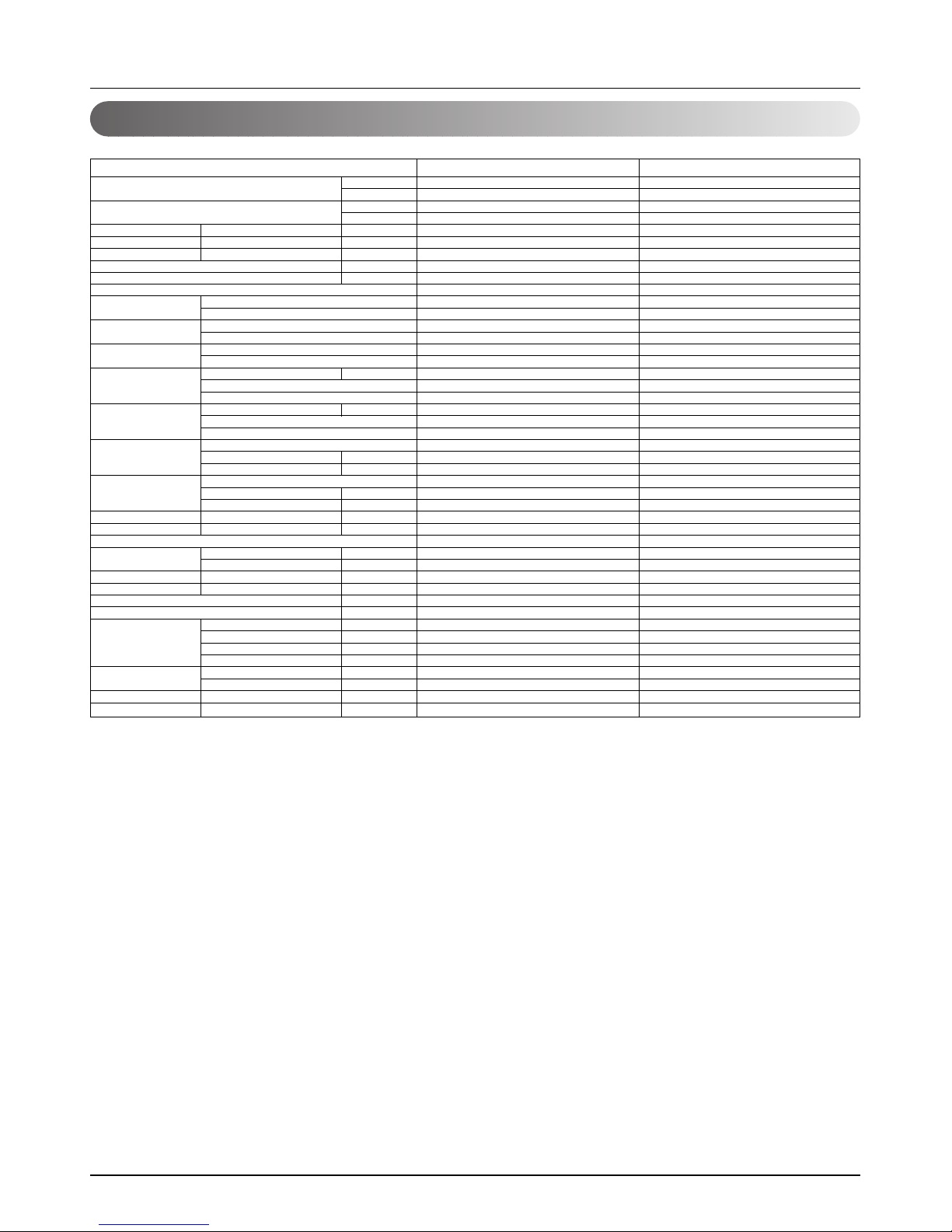
Product Specifications
Rated Cooling Capacity kcal/hr(W)
Btu/hr
Ratedl Heating Capacity kcal/hr(W)
Btu/hr
Air Circulation Indoor(H/M/L)
CMM(CFM)
Setting temperature range °C
Fan motor Output W
Model
No. of Poles
Input W
Running Current A
Capacitor µF/Vac
Fan Type
No. Used / Diameter EA/inch(mm)
Fan RPM Cooling(H/M/L) rpm
Heating(H/M/L) rpm
Noise Level
(Sound Press,1m)
H/M/L dBA
Temperature controller
Coil Tube Size (OD) inch(mm)
Fins per inch
No. of Rows & Column
Dehumidification Rate l/h
Dimensions (W*H*D) Indoor inch(mm)
Net Weight kg(lbs)
Piping Liquid inch(mm)
Connection Gas inch(mm)
Drain hose (ID Ø)mm
Packing Dimension (W*H*D) inch(mm)
Stuffing Quantity
Without(Without) S/Parts 20/40ft
3024(3517) 4536(5274) 6048(7032) 6653(7377)
12000 18000 24000 26400
3478(4044) 5116(5949) 6955(8089) 7635(8880)
13800 20300 27600 30300
10.0/8.3/6.5(353/293/230) 13.5/12/11(477/424/388) 15/13.5/12(530/477/424) 18/16/14(636/564/494)
18~30/16~30 18~30/16~30 18~30/16~30 18~30/16~30
17.5 30 35 42.5
IC-18422LG31A IC-9430LGCG IC-9430LGCE OBM-3019P2
4444
43 53 63 81
0.23 0.23 0.27 0.38
1.5/370 1.5/370 1.5/370 1.5/370
Cross Flow Fan Cross Flow Fan Cross Flow Fan Cross Flow Fan
1/3.7(95) 1/3.1(80) 1/3.1(80) 1/3.1(80)
1240/1120/900 1090/990/890 1160/1060/960 1220/1110/1010
1240/1120/900 1090/990/890 1160/1060/960 1220/1110/1010
40 / 36 / 31 43 / 40 / 37 45 / 42 / 39 45 / 42 / 39
Thermistor Thermistor Thermistor Thermistor
0.197(5.0) 0.275(7.0) 0.275(7.0) 0.275(7.0)
20 18 20 20
2R 12C 2R 12C 2R 14C 2R 14C
1.2 2.3 3.2 3.5
35.4*7.9*19.3 (900*200*490) 47.2*8.1*24.2 (1200*205*615) 47.2*8.1*24.2 (1200*205*615) 47.2*8.1*24.2 (1200*205*615)
12(26.5) 30(66.1) 30(66.1) 30(66.1)
1/4(6.35) 1/4(6.35) 1/4(6.35) 1/4(6.35)
3/8(9.52) 1/2(12.7) 1/2(12.7) 5/8(15.88)
20 20 20 20
38.2*11.2*22.2 (970*285*565) 50.8*11.4*27.4 (1272*290*696) 50.8*11.4*27.4 (1272*290*696) 50.8*11.4*27.4 (1272*290*696)
189/383 102/219 102/219 102/219
Ceiling & Floor (Convertible)
AVNH126ELAB AVNH186BLAB AVNH246BLAB AVNH306BLAB
Indoor Unit Type
Model
Notes:
1. Capacities are based on the following conditions:
Cooling : - Indoor Temperature 27˚C(80.6˚F) DB / 19˚C(66.2˚F) WB
- Outdoor Temperature 35˚C(95˚F) DB / 24˚C(75.2˚F) WB
- Interconnecting Piping Length 7.5m
- Level Difference of Zero.
Heating : - Indoor Temperature 20˚C(68˚F) DB / 15˚C(59˚F) WB
- Outdoor Temperature 7˚C(44.6˚F) DB / 6˚C(42.8˚F) WB
- Interconnecting Piping Length 7.5m
- Level Difference of Zero.
2. Capacities are Net Capacities.
3. Due to our policy of innovation some specifications may be changed without notification.
Service Manual 25
Product Specifications
10600~12100(12300~14000) 12100~13600(14000~15800)
42000~48000 48000~56000
12200~13900(14200~16200) 12200~16200(16200~18900)
48300~55200 55200~64400
1900~5940/1920~6100 2080~7000/2250~7930
8.5~26.6/8.6~27.3 9.3~31.3/10.1~35.5
43 74
1,220~240,50 1,220~240,50
90 ~ 97 90 ~ 97
44
e-Scroll e-Scroll
--
Rotary Rotary
Internal Internal
Rotary Rotary
Internal Internal
7100(250.4) 7100(250.4)
R410A R410A
L.E.V L.E.V
0.276(7.0) 0.276(7.0)
18 18
2R,53C*2 2R,53C*2
ARE676E01 ARE676E01
270 270
10/370 10/370
Propeller Propeller
1/20.7(526) 1/20.7(526)
Top Discharge Top Discharge
90(3179) 90(3179)
59/56 59/56
Invertion cycle Invertion cycle
3/8 (9.52) 3/8 (9.52)
3/4 (19.05) 3/4 (19.05)
31.7*59.5*28.7 (806*1,512*730) 31.7*59.5*28.7 (806*1,512*730)
142(312) 148(326)
3*5.0 3*5.0
4*0.75 (Includes earth) 4*0.75 (Includes earth)
110 110
50 50
60 60
15 15
30 30
11
33.9*61.0*28.7 (860*1,550*730) 33.9*61.0*28.7 (860*1,550*730)
18/39 18/39
Cooling Capacity kcal/hr(W)
Btu/hr
Heating Capacity kcal/hr(W)
Btu/hr
Input Cooling/Heating W
Running Current Cooling/Heating A
Starting Current Cooling/Heating A
Power Supply Ø,V,Hz
Power Factor %
Max. Number of Connectable Indoor Units
Compressor (Inverter) Type
O.L.P Type(model name)
Compressor (Constant-1) Type
O.L.P Type(model name)
Compressor (Constant-2) Type
O.L.P Type(model name)
Refrigerant charge Charge * g(oz)
Type
Control
Coil Tube Size (OD) inch(mm)
Fins per inch
No. of Rows & Column/No.
Fan motor Model
Output W
Capacitor µF/Vac
Fan Type
No. Used / Diameter EA/inch(mm)
Discharge Side / Top
Air Circulation Outdoor CMM(CFM)
Noise Level(H/L) Sound Press,1m dB(A)±1
Defrosting
SVC Valve Liquid inch(mm)
Gas inch(mm)
Dimensions W*H*D inch(mm)
Net Weight Outdoor kg(lbs)
Power Supply Cable No.* mm
2
Interunit Cable No.* mm
2
Max. Interunit Total Piping m
Piping Length Total Main Piping m
Total Branch Piping m
For One Room m
Max. Installation Indoor Unit~Outdoor Unit m
Height Difference Indoor Unit~Indoor Unit m
Packing Dimension W*H*D inch(mm)
Stuffing Quantity With(Without) S/Parts 20/40ft
AUUW4860 AUUW6060
Model
Outdoor Unit
Notes:-
1. Capacities are based on the following conditions:
Cooling: - Indoor Temperature 27˚C(80.6ÜV) DB /19˚C(66.2ÜV) WB
- Outdoor Temperature 35˚C(95ÜV) DB /24˚C(75.2ÜV) WB
Heating: - Indoor Temperature 20˚C(68ÜV) DB / 15˚C(59ÜV) WB
- Outdoor Temperature 7˚C(44.6ÜV) DB / 6˚C(42.8ÜV) WB
Piping Length - Interconnecting Pipe Length 7.5m(25ft)
- Level Difference of Zero
2. * : Full factory charge is shipped in the outdoor unit. Chargeless for 30m of piping length.
3. Due to our policy of innovation some specifications may be changed without notification.
26 Synchro Air Conditioner
Product Specifications
Cooling Capacity kcal/hr(W)
Btu/hr
Heating Capacity kcal/hr(W)
Btu/hr
Input Cooling/Heating W
Running Current Cooling/Heating A
Starting Current Cooling/Heating A
Power Supply Ø,V,Hz
Power Factor %
Number of Connectable Indoor Units
Compressor Locked Rotor Amp. A
Type
Quantity No
Model
Maker
Capacity kcal/hr(Btu/hr)
Motor Type
Motor Input W
Oil Type
Oil Charge cc
O.L.P Type(model name)
Refrigerant Charge * g(oz)
Type
Control
Outdoor Coil Tube Size (OD) inch(mm)
Fins per inch
No. of Rows & Column/No.
Outdoor fan motor Output W
Model
No. Used / No. of Poles
Input W
Running Current A
Capacitor µF/Vac
Outdoor Fan Type
No. Used / Diameter EA/inch(mm)
Discharge Side / Top
Speed rpm
Air Circulation Outdoor CMM(CFM)
Noise Level(Sound Press,1m)
Outdoor dB(A)±1
SVC Valve Liquid inch(mm)
Gas inch(mm)
Dimensions W*H*D inch(mm)
Net Weight Outdoor kg(lbs)
Power Supply Cable No.* mm
2
Connecting Cable No.* mm
2
Max Interunit Total Piping m
Piping Length Total Main Piping m
Total Branch Piping m
For One Room m
Max. Installation Indoor Unit - Outdoor Unit m
Height Difference Indoor Unit - Indoor Unit m
Packing Dimension (W*H*D) inch(mm)
Stuffing Quantity With(Without) S/Parts 20/40ft
12096(14607) 18144(21101) 24192(28135)
48000 72000 96000
13305(15474) 19958(23211) 27820(32355)
52800 79200 110400
5300 / 5050 8000 / 7700 11100 / 11000
10.0 / 9.5 14.7 / 14.4 20 / 19.7
---
3,380~415,50 3,380~415,50 3,380~415,50
82 80 83
Single / Duo / Trio / Quartet Duo / Trio / Quartet Duo / Trio / Quartet
42 at 420V 24 / 27 63 at 420V
Rotary Rotary Scroll
232
GPT330YAA 5JS290PBA21 AR061YAA
LG Matsushita Electric LG
6854(27200) at 50Hz & 380V 6376(25301) at 50Hz & 380V 12625(50100) at 50Hz & 380V
Three Phase Induction Motor Three Phase Induction Motor Three Phase Induction Motor
2550 2680 5330
FVC68D(PVE) FV50S(PVE) FVC68D(PVE)
1200 1130 1800
Internal Type(UBUKATA) IT(Internal Thermostat) Internal Type(UP18TA057)
4200(148.1) 7100(250.4) 7800(275.1)
R-410A R-410A R-410A
L.E.V L.E.V L.E.V
0.276(7.0) 0.276(7.0) 0.276(7.0)
17 17 18
2R 52C
2R 17C + 3R 36C + 2R 17C + 2R 36C 2R 17C + 1R 36C + 2R 17C + 2R 36C
70 271 271
AMR071B9 ARE676E01 ARE676E01
2/6 1/6 2/6
168 429 429
- 1.87 1.87
6/370 10/370 10/370
Propeller Propeller Propeller
2/18.1(460) 1/20.7(526) 2/20.7(526)
Side Discharge Top Discharge Top Discharge
900 850 850
53(1872*2) 90(3179) 185(6533)
56 58 60
3/8 (9.52) 3/8 (9.52) 1/2 (12.7)
3/4 (19.05) 1 (25.4) 1 (25.4)
35.4*45.8*14.5(900*1165*370) 31.5*56.7*27.1(800*1440*690) 50.4*56.7*27.1(1280*1440*690)
105(231) 150(331) 299(659)
5*5.5 (Includes earth) 5*5.5 (Includes earth) 5*5.5 (Includes earth)
4*0.75 (Includes earth) 4*0.75 (Includes earth) 4*0.75 (Includes earth)
110 110 110
50 50 50
60 60 60
15 15 15
30 30 30
111
41.7*48.0*18.3(1060*1220*465) 34.4*61.0*29.7(875*1550*755) 53.1*62.6*29.9(1350*1590*760)
27 / 55 18 / 39 12 / 25
AUUH488B AUUH7280 AUUH10080
Model
Notes:-
1. Capacities are based on the following conditions:
Cooling: - Indoor Temperature 27˚C(80.6ÜV) DB /19˚C(66.2ÜV) WB
- Outdoor Temperature 35˚C(95ÜV) DB /24˚C(75.2ÜV) WB
Heating: - Indoor Temperature 20˚C(68ÜV) DB / 15˚C(59ÜV) WB
- Outdoor Temperature 7˚C(44.6ÜV) DB / 6˚C(42.8ÜV) WB
Piping Length - Interconnecting Pipe Length 7.5m(25ft)
- Level Difference of Zero
2. * : Full factory charge is shipped in the outdoor unit. Chargeless for 30m of piping length.
3. Due to our policy of innovation some specifications may be changed without notification.
Service Manual 27
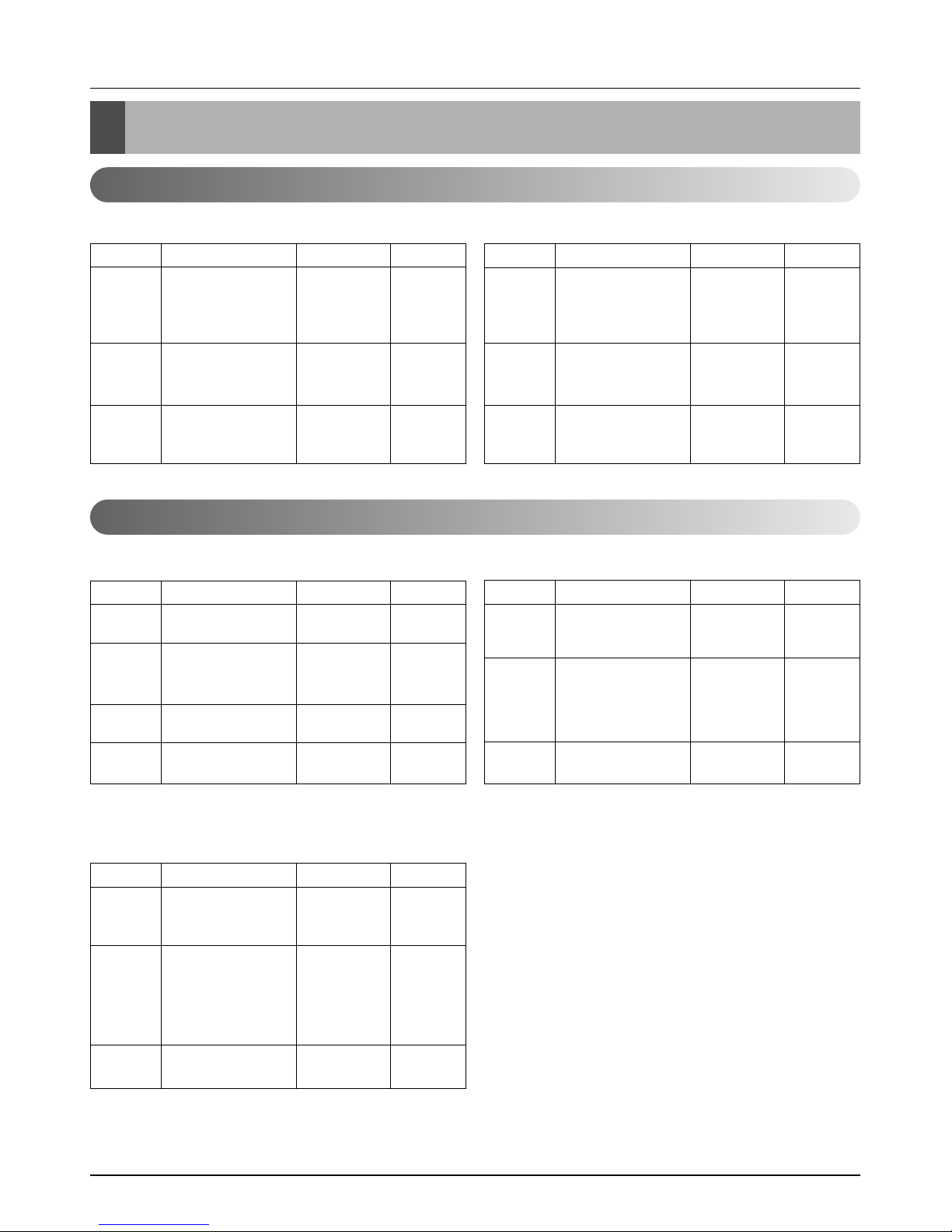
Combination table
Combination table
MPS Inverter
MPS Variable
AUUW4860 AUUW6060
Synchro Combination(k Btu/h) Total(k Btu/h) Branch Kit
Duo(2 Unit)
Trio(3 Unit)
Quartet
(4 Unit)
18 + 24 (2:3)
24 + 24 (1:1)
24 + 30 (2:3)
18 + 18 + 18
(1:1:1)
12 + 12 + 12 + 12
(1:1:1:1)
42
48
54
54
48
PMUB111A
PMUB1111A
PMUB23A
PMUB11A
PMUB23A
Synchro Combination(k Btu/h) Total(k Btu/h) Branch Kit
Duo(2 Unit)
Trio(3 Unit)
Quartet
(4 Unit)
24 + 30 (2:3)
30 + 30 (1:1)
24 + 36 (2:3)
18 + 18 + 24 (1:1:2)
18 +18 +18 (1:1:1)
12 + 12 + 12 + 12
(1:1:1:1)
54
60
60
60
54
48
PMUB112A
PMUB111A
PMUB1111A
PMUB23A
PMUB11A
PMUB23A
AUUH7280AUUH488B
Synchro Combination(k Btu/h) Total(k Btu/h) Branch Kit
Duo(2 Unit)
Trio(3 Unit)
Quartet
(4 Unit)
30 + 36(2:3)
36 + 36(1:1)
18 + 24 + 24(1:2:2)
18 + 18 + 36(1:1:2)
24 + 24 + 24(1:1:1)
24 + 24 + 30(1:1:2)
18 + 18 + 18 + 18
(1:1:1:1)
68
72
66
72
72
78
72
PMUB122A
PMUB112A
PMUB111A
PMUB112A
PMUB1111A
PMUB23A
PMUB11A
Synchro Combination(k Btu/h) Total(k Btu/h) Branch Kit
Single
(1 Unit)
Trio
(3 Unit)
Duo
(2 Unit)
Quartet
(4 Unit)
48
18 + 18 + 18 (1:1:1)
12 + 12 + 12 + 12 (1:1:1:1)
18 + 24 (2:3)
24 + 24 (1:1)
24 + 30 (2:3)
48
54
42
48
54
48
PMUB23A
PMUB11A
PMUB23A
PMUB1111A
PMUB111A
-
AUUH10080
Synchro Combination(k Btu/h) Total(k Btu/h) Branch Kit
Duo(2 Unit)
Trio(3 Unit)
Quartet
(4 Unit)
36 + 48 (2:3)
36 + 60 (2:3)
48 + 48 (1:1)
24 + 24 + 36(1:1:2)
24 + 24 + 30(1:1:2)
30 + 30 + 30(1:1:1)
30 + 30 + 36(1:1:2)
30 + 36 + 36(1:2:2)
24 + 24 +24 + 24
(1:1:1:1)
84
96
96
84
84
90
96
102
96
PMUB112A
PMUB112A
PMUB111A
PMUB112A
PMUB122A
PMUB1111A
PMUB23A
PMUB23A
PMUB11A
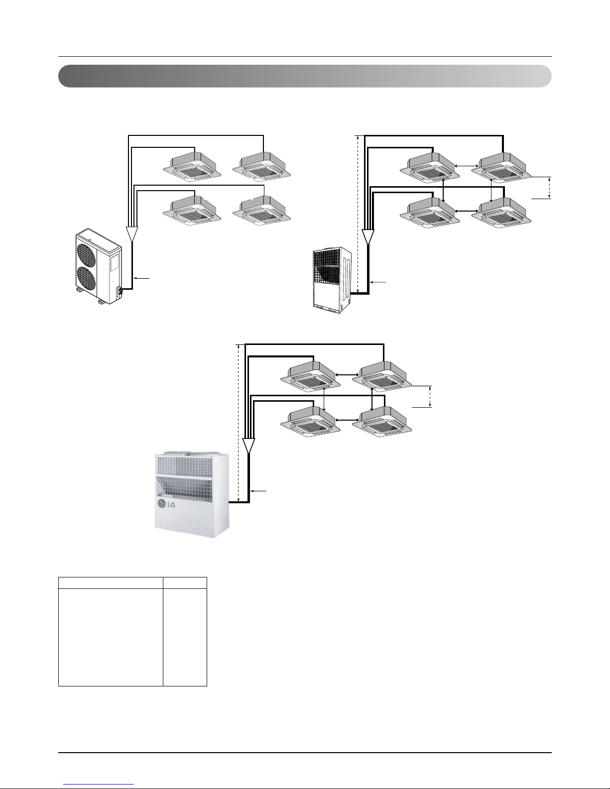
54 Synchro Air Conditioner
Installation
Branch
Main (L1)
h1
b
L2
L3
L4
L5
h2
Branch
Main (L1)
h1
b
L2
L3
L4
L5
h2
L1
L2
L3
L4
L5
Outdoor
Unit
Indoor Unit
Piping length and the elevation
Install the branch pipe so that pipe length and difference between high and low will not exceed below SPEC.
AUUW4860/AUUW6060/AUUH7280
AUUH488B
AUUH10080
• When installing the branch pipe, direction and angle of installation is not limited.
• Take care so that burrs and foreign material may not enter into the cutting surface when connecting.
• Don’t use the liquid pipe by too bending or twisting.
Pipe Length(m)
Total(Main+Branch)
Main Pipe(L1)
Branch Pipe----Total
Each
In out (h1)
In-In (h2)
L1+L2/L3/L4/L5
Indoor-Indoor_(b)
Spec.
110
50
60
15
30
1
65
10
Service Manual 55
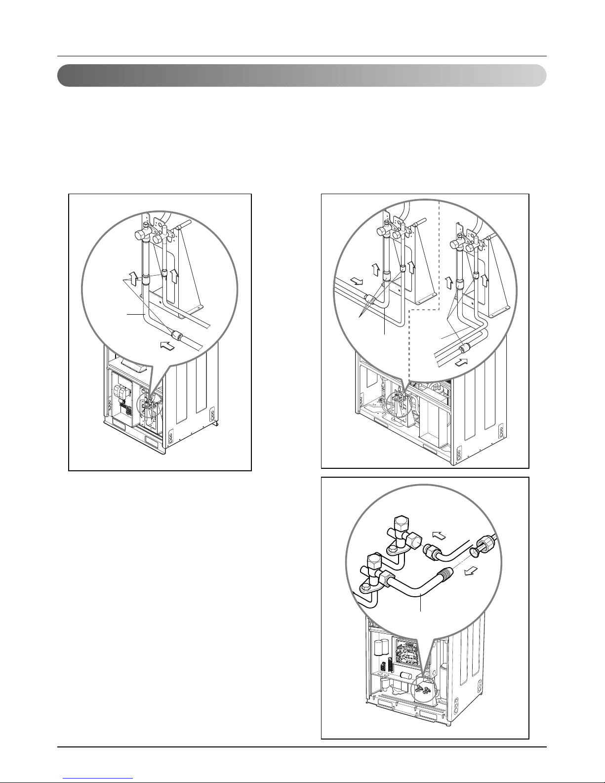
Installation
1. Form the piping according to its routing. Avoid bending and bending back the same piping point more than
three times. (This will result in hardening the pipe.)
2. After deforming the piping, align centers of the union fitting of the indoor unit and the piping, and tighten them
firmly with wrenches.
3. Connect pipe to the service valve or ball valve which is located below the outdoor unit.
4. After completing the piping connection, be sure to check if there is gas leakage in indoor and outdoor connection.
AUUH7280
AUUH10080
Elbow
Welding
Elbow
Elbow
Welding
Welding
AUUW4860AUUW6060
Elbow
Piping Connection
56 Synchro Air Conditioner
Installation
2. AUUH7280/AUUH10080
For additional charging method, see below table.
❈ Note: If total additional charge value after calculation comes out to be negative, then do not consider additional
charge.
CAUTION:
• Rated performance for refrigerant line length of:7.5m
• Capacity is based on standard length and maximum allowance length is on the basis of
reliability.
• Improper refrigerant charge may result in abnormal cycle.
• Oil trap should be installed every 10 meters.
Synchro Refrigerant Additional charging (kg)
Duo
Refrigerant = (L1 - 5) x 0.05 + (L2 + L3 - 20) x A
Tr io
Refrigerant = (L1 - 5) x 0.05 + (L2 + L3 + L4 - 20) x A
Quartet
Refrigerant = (L1 - 5)
x
0.05 + (L2 + L3 + L4 + L5 - 20)
x
A
A
Refrigerant Branch
Pipe (mm)
Ø 6.35
Ø 9.52
0.03 kg/m
0.05 kg/m
(L1=Main Pipe, L2~L5 : Branch Pipe)
1. AUUH488B/AUUW4860/AUUW6060
There is not additional charging of refrigerant by main pipe of 30m below.
For additional charging method, see below table.
❈ Note: If total additional charge value after calculation comes out to be negative, then do not consider additional
charge.
CAUTION:
• Rated performance for refrigerant line length of:7.5m
• Capacity is based on standard length and maximum allowance length is on the basis of
reliability.
• Improper refrigerant charge may result in abnormal cycle.
• Oil trap should be installed every 10 meters.
Synchro Refrigerant Additional charging (kg)
Duo
Refrigerant = (L1-30) x A + (L2+L3-20) x 0.03
Tr i o
Refrigerant = (L1-30) x A + (L2+L3+L4-20) x 0.03
Quartet
Refrigerant = (L1-30)
x A +
(L2+L3+L4+L5-20)
x
0.03
Model
AUUH488B
AUUW4860/AUUW6060
A
0.07
0.05
(L1=Main Pipe, L2~L5 : Branch Pipe)
Refrigerant Additional Charging Method
Service Manual 57
Installation
Branch Kit
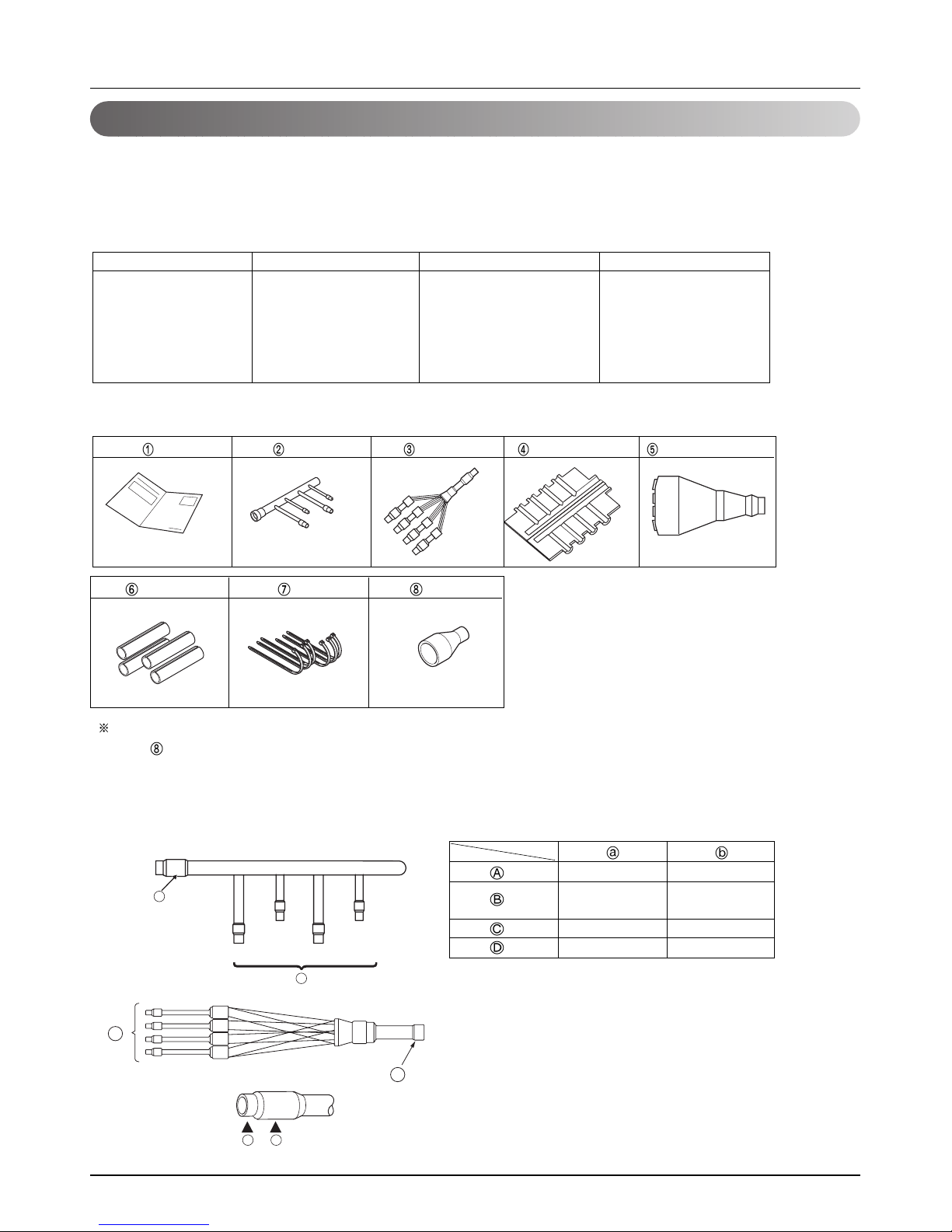
1. Type of branch pipe
Separately use a branch pipe depending on indoor capacity for installation.
Unbalance type of branch pipe must be connected depending on large capacity or small capacity.
2. Accessory for Installation
3. SPEC for branch pipe connection part
• Procure other parts than those specified in this manual in the scene
• No.
parts are used for connection of 48/60k indoor unit.
Indoor Classification
2 UNIT
3 UNIT
4 UNIT
Model Name
PMUB11A
PMUB23A
PMUB122A
PMUB112A
PMUB111A
PMUB1111A
Capacity Ratio(%)
50:50 (1:1)
40:60 (2:3)
20:40:40 (1:2:2)
25:25:50 (1:1:2)
33:33:33 (1:1:1)
25:25:25:25(1:1:1:1)
Remark
Unbalance type
Unbalance type
Unbalance type
Manual Gas pipe Liquid pipe Insulation(Gas pipe) Insulation(Liquid pipe)
Insulation Band Socket
(I.D)
Ø19.05(3/4) Ø25.4(1)
Ø9.52(3/8) Ø12.7(1/2)
Ø12.7(1/2) Ø15.88(5/8)
Ø6.35(1/4) Ø9.52(3/8)
Ø9.52(3/8) Ø12.7(1/2)
a
b
B
A
D
C
(Ø15.88→Ø19.05)
(Gas pipe)
(Liquid pipe)
(): inch
58 Synchro Air Conditioner
Installation
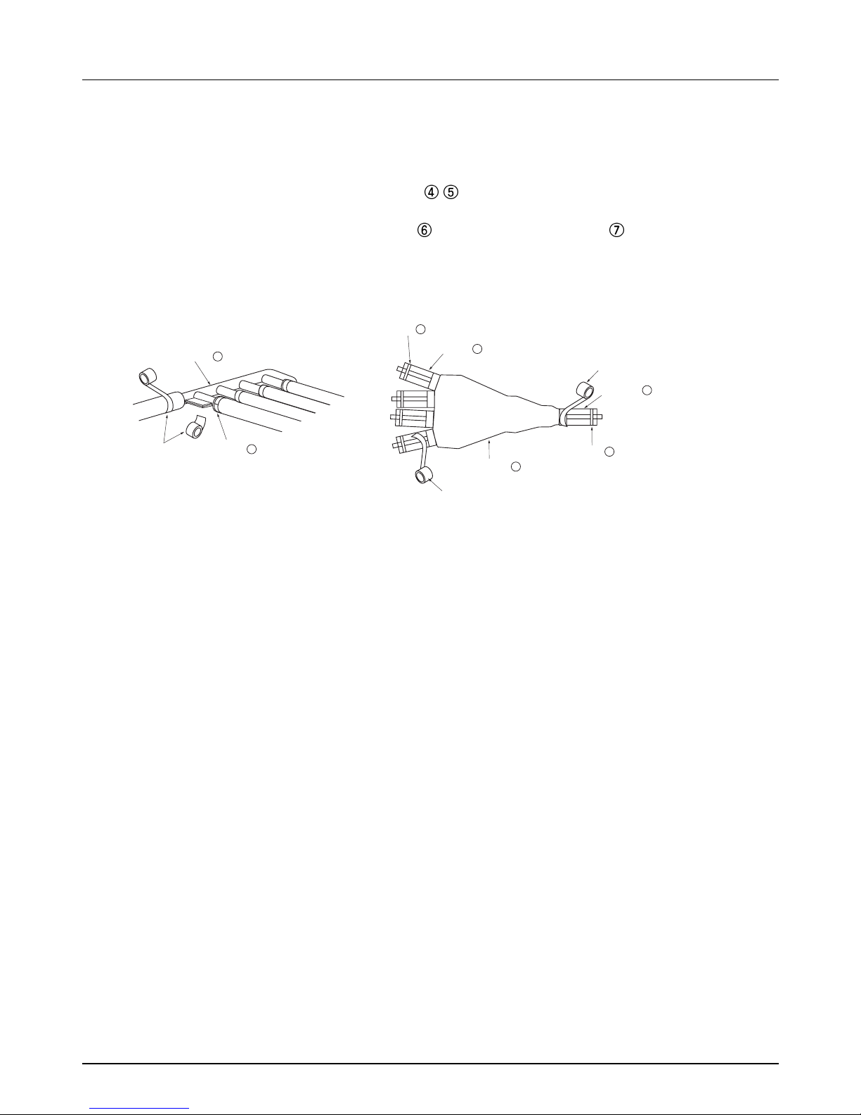
4 .Thermal insulation work
• Securely wrap the refrigerant and the branch pipe by using thermal insulation materials provided.
When using thermal insulation materials released, use withstand heat insulation materials
(thickness of more than 15mm).
• Securely adhere thermal insulation materials
wrapping the branch pipe so that they do not
widen.
After wrapping them with auxiliary materials
, bound them with a band .
• Finish the work by wrapping with a vinyl tape after the insulation material work.
Vinyl Tape
Insulation
4
Band 7
Insulation
6
Insulation
5
Insulation
6
Band 7
Band 7
Vinyl Tape
Vinyl Tape
Service Manual 59
Installation
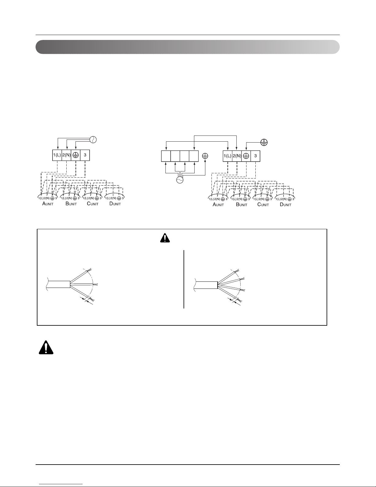
Wiring Connection
1. All wiring must comply with LOCAL REGULATIONS.
2. Select a power source that is capable of supplying the current as required by the air conditioner.
3. Feed the power source to the unit via a distribution switch board designed for this purpose.
4. The terminal screws inside the control box may be loose due to vibration during transport.
Check the screws for loose connection.
(Running the air conditioner with loose connection can overload and damage electrical components.)
5. Always ground the air conditioner with a grounding wire and connector to meet the LOCAL REGULATION.
Terminal Block
(Outdoor Unit)
Power
Input
Terminal Block
(Indoor Unit)
The power cord connected to the outdoor unit should be
complied with the following specifications (Rubber
insulation, type H05RN-F approved by HAR or SAA).
If the supply cord is damaged, it must be replaced by a special cord or assembly available from the manufacturer of its service agent.
The connecting cable connected to the indoor and outdoor
unit should be complied with the following specifications
(Rubber insulation, type H05RN-F approved by HAR or SAA).
CAUTION
20mm
GN/YL
NORMAL
CROSS-SECTIONAL
AREA 1.25mm
2
NORMAL
CROSS-SECTIONAL
AREA 5.5mm
2
20mm
GN/YL
Terminal Block
(Outdoor Unit)
Terminal Block
(Indoor Unit)
RST N
Power
Input
WARNING:
Make sure that the screws of the terminal are free from looseness.
AUUW4860 / AUUW6060
AUUH488B/AUUH7280/AUUH10080
60 Synchro Air Conditioner
Installation
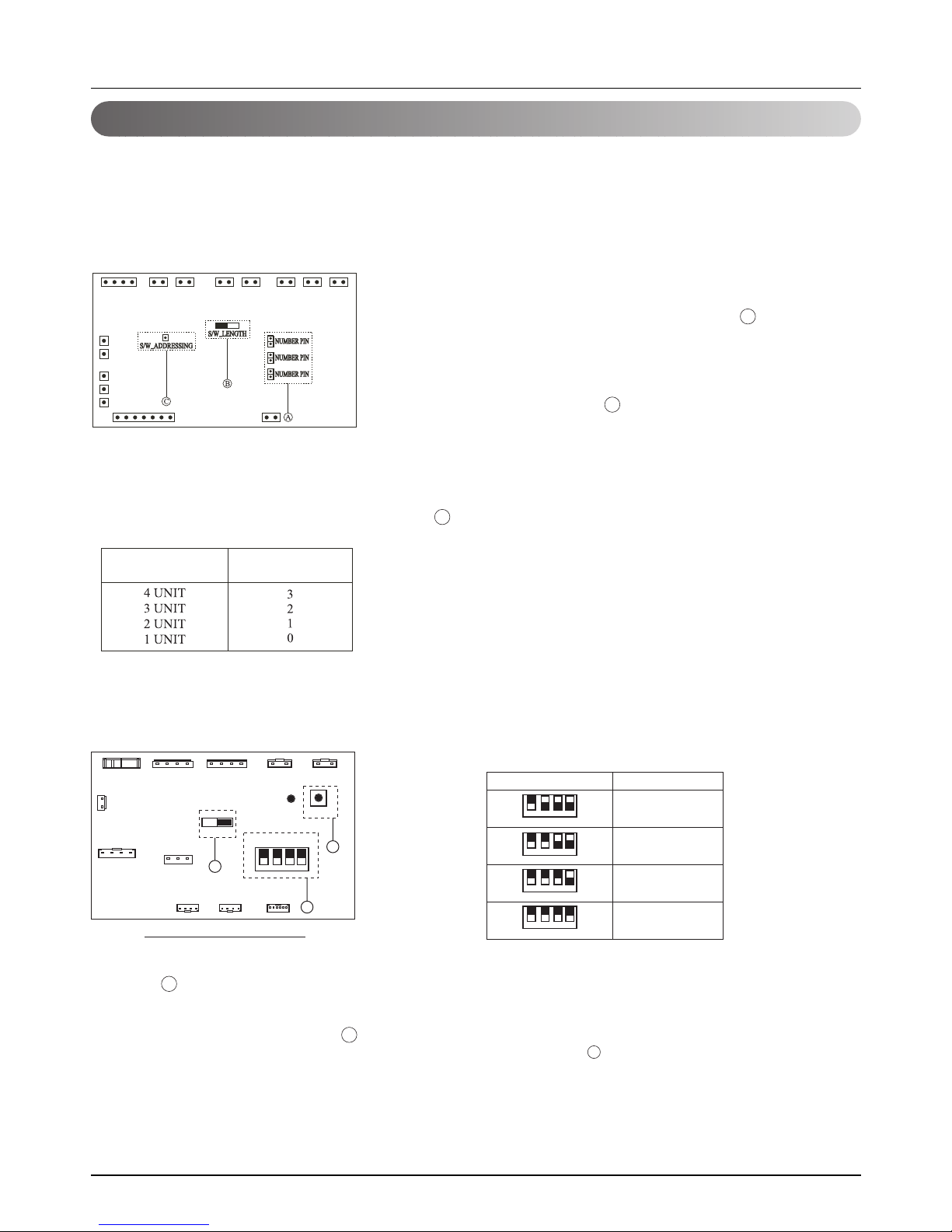
Auto addressing
Auto addressing work should be done for simultaneous operation.
Addressing work assigns address to each Indoor Unit.
When firstly installing product or replacing the Indoor Unit PCB.
3. Auto Addressing Method
Table.a ZONE SW1 Setting
TEST_SW1
LED01T
JIG_SW
1234
ZONE SW1
Main PCB
Main PCB
Fig.a Outdoor PCB diagram
C
B
A
1. JIG_SW Setting
Check the JIG_SW to the right, or not set the JIG_SW to
the right.( A )
2. ZONE SW1 Setting
Set the ZONE SW1 as below Table.a ( B )
❈ S/W1 is not used.
❈ 1 means S/W up.
0 means S/W down.
1. Indoor unit connection numbers separation s/w
Accordingly insert the Number pin numbers as below in
accordance with the indoor unit connection numbers.( A )
(Inserting order is irrespective.)
3. Auto Addressing Method
1) Turn main power on.
2) Press the S/W_ADDRESSING for about
5~7 seconds( C )
3) Turn the Indoor unit on after 1~2minutes after
pressing
the s/w.(If performing the ADDRESSING work at the
PCB, the green LED rapidly flickers.)
2. Operation method of pipe length s/w
Convert the s/w toward "long pipe" direction when
installing more than main pipe of 30m ( B ).
* Work procedure
1) Set JIG_SW and ZONE SW1 correctly.
2) Turn on main power.
3) Press the TEST_SW1 for about 3 seconds within 3minutes After
main power on.( C )
4) After step 3), the LED01T(green LED) rapidly flickers.
When Addressing work is done, green LED is off, else LED stops
flickering and lights continuously.
5) If you fail to perform the Addressing work,
repeat step 2),3).
(Outdoor PCB Board)
Connection
numbers
AUUW4860/AUUW6060
AUUH488B/AUUH7280/AUUH10080
ZONE SW1
Indoor Unit No.
12
34
x0
00
x1
00
x
1
10
2(Duo)
1(Single)
3(Trio)
4(Quartet)
12
3 4
12
3
4
x
1
11
12
3
4
 Loading...