

LG ATNQ30GPLA4 INSTALLATION MANUAL

INSTALLATION MANUAL
CEILING CASSETTE
AIR
CONDITIONER
www.lg.com
Copyright © 2016 - 2019 LG Electronics Inc. All Rights Reserved.
ENGLISH
ESPAÑOL
Please read this installation manual completely before installing the product.
Installation work must be performed in accordance with the national wiring
standards by authorized personnel only.
Please retain this installation manual for future reference after reading it
thoroughly.
P/NO.: MFL70520306
REV.00_190413
• Do not cool excessively indoors. This may be harmful for your health and may consume more
electricity.
• Block sunlight with blinds or curtains while you are operating the air conditioner.
• Keep doors or windows closed tightly while you are operating the air conditioner.
• Adjust the direction of the air flow vertically or horizontally to circulate indoor air.
• Speed up the fan to cool or warm indoor air quickly, in a short period of time.
• Open windows regularly for ventilation as the indoor air quality may deteriorate if the air conditioner
is used for many hours.
• Clean the air filter once every 2 weeks. Dust and impurities collected in the air filter may block the
air flow or weaken the cooling / dehumidifying functions.
For your records
Staple your receipt to this page in case you need it to prove the date of purchase or for warranty
purposes. Write the model number and the serial number here:
Model number :
Serial number :
You can find them on a label on the side of each unit.
Dealer’s name :
Date of purchase :
Here are some tips that will help you minimize the power consumption when you use the air
conditioner. You can use your air conditioner more efficiently by referring to the instructions
below:
TIPS FOR SAVING ENERGY
ENGLISH
TIPS FOR SAVING ENERGY
2
3
IMPORTANT SAFETY INSTRUCTIONS
READ ALL INSTRUCTIONS BEFORE USING THE APPLIANCE.
Always comply with the following precautions to avoid dangerous situations and ensure peak
performance of your product.
WARNING
It can result in serious injury or death when the directions are ignored.
CAUTION
It can result in minor injury or product damage when the directions are ignored.
WARNING
• Installation or repairs made by unqualified persons can result in hazards to you and others.
• Installation MUST conform with local building codes or, in the absence of local codes, with
the Nation Electrical Code NFPA 70/ANSI C1-1003 or current edition and Canadian Electrical
Code Part1 CSA C.22.1.
• The information contained in the manual is intended for use by a qualified service technician
familiar with safety procedures and equipped with the proper tools and test instruments.
• Failure to carefully read and follow all instructions in this manual can result in equipment
malfunction, property damage, personal injury and/or death.
Installation
• Always perform grounding.
- Otherwise, it may cause electrical shock.
• Don’t use a power cable, a plug or a loose socket which is damaged.
- Otherwise, it may cause a fire or electrical shock.
• For installation of the product, always contact the service center or a professional installation
agency.
- Otherwise, it may cause a fire, electrical shock, explosion or injury.
• Securely attach the electrical part cover to the indoor unit and the service panel to the outdoor unit.
- If the electrical part cover of the indoor unit and the service panel of the outdoor unit are not
attached securely, it could result in a fire or electric shock due to dust, water, etc.
• Always install an air leakage breaker and a dedicated switching board.
- No installation may cause a fire and electrical shock.
• Do not keep or use flammable gases or combustibles near the air conditioner.
- Otherwise, it may cause a fire or the failure of product.
• Ensure that an installation frame of the outdoor unit is not damaged due to use for a long time.
- It may cause injury or an accident.
• Do not disassemble or repair the product randomly.
- It will cause a fire or electrical shock.
• Do not install the product at a place that there is concern of falling down.
- Otherwise, it may result in personal injury.
• Use caution when unpacking and installing.
- Sharp edges may cause injury.
Operation
• Do not share the outlet with other appliances.
- It will cause an electric shock or a fire due to heat generation.
• Do not use the damaged power cable.
- Otherwise, it may cause a fire or electrical shock.
• Do not modify or extend the power cable randomly.
- Otherwise, it may cause a fire or electrical shock.
!
!
!
ENGLISH
IMPORTANT SAFETY INSTRUCTIONS

• Take care so that the power cable may not be pulled during operation.
- Otherwise, it may cause a fire or electrical shock.
• Unplug the unit if strange sounds, smell, or smoke comes from it.
- Otherwise, it may cause electrical shock or a fire.
• Keep the flames away.
- Otherwise, it may cause a fire.
• Take the power plug out if necessary, holding the head of the plug and do not touch it with wet
hands.
- Otherwise, it may cause a fire or electrical shock.
• Do not use the power cable near the heating tools.
- Otherwise, it may cause a fire and electrical shock.
• Do not open the suction inlet of the indoor/outdoor unit during operation.
- Otherwise, it may electrical shock and failure.
• Do not allow water to run into electrical parts.
- Otherwise, it may cause the failure of machine or electrical shock.
• Hold the plug by the head when taking it out.
- It may cause electric shock and damage.
• Never touch the metal parts of the unit when removing the filter.
- They are sharp and may cause injury.
• Do not step on the indoor/outdoor unit and do not put anything on it.
- It may cause an injury through dropping of the unit or falling down.
• Do not place a heavy object on the power cable.
- Otherwise, it may cause a fire or electrical shock.
• When the product is submerged into water, always contact the service center.
- Otherwise, it may cause a fire or electrical shock.
• Take care so that children may not step on the outdoor unit.
- Otherwise, children may be seriously injured due to falling down.
CAUTION
Installation
• Install the drain hose to ensure that drain can be securely done.
- Otherwise, it may cause water leakage.
• Install the product so that the noise or hot wind from the outdoor unit may not cause any damage to
the neighbors.
- Otherwise, it may cause dispute with the neighbors.
• Always inspect gas leakage after the installation and repair of product.
- Otherwise, it may cause the failure of product.
• Keep level parallel in installing the product.
- Otherwise, it may cause vibration or water leakage.
• Means for disconnection must be incorporated in the fixed wiring in accordance with the wiring
rules.
Operation
• Avoid excessive cooling and perform ventilation sometimes.
- Otherwise, it may do harm to your health.
• Use a soft cloth to clean. Do not use wax, thinner, or a strong detergent.
- The appearance of the air conditioner may deteriorate, change color, or develop surface flaws.
• Do not use an appliance for special purposes such as preserving animals vegetables, precision
machine, or art articles.
- Otherwise, it may damage your properties.
• Do not place obstacles around the flow inlet or outlet.
- Otherwise, it may cause the failure of appliance or an accident.
!
ENGLISH
IMPORTANT SAFETY INSTRUCTIONS
4
ENGLISH
5
2 TIPS FOR SAVING ENERGY
3 IMPORTANT SAFETY INSTRUCTIONS
6 INSTALLATION PLACES
7 THE INDOOR UNIT INSTALLATION
8 Indoor Unit Drain Piping
9 Wiring Connection
11 OPERATING INSTRUCTION
11 How to insert the Batteries
11 Wireless Remote Controller Maintenance
11 Operating Method
12 INSTALLATION OF DECORATIVE PANEL(ACCESSORY)
14 TEST RUNNING
15 INSTALLATION INSTRUCTIONS
15 Installer Setting - Setting Address of Central Control
15 Installer Setting - Checking Address of Central Control
16 Installer Setting -How to enter installer setting mode
17 Installer Setting - Installer Setting Code Table
TABLE OF CONTENTS
TABLE OF CONTENTS
6
ENGLISH
INSTALLATION PLACES
INSTALLATION PLACES
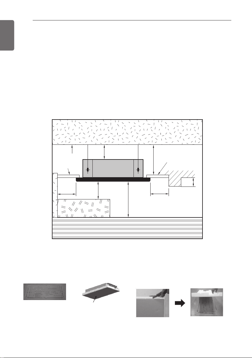
- There should not be any heat source or steam near the unit.
- There should not be any obstacles to prevent the air circulation.
- A place where air circulation in the room will be good.
- A place where drainage can be easily obtained.
- A place where noise prevention is taken into consideration.
- Do not install the unit near the door way.
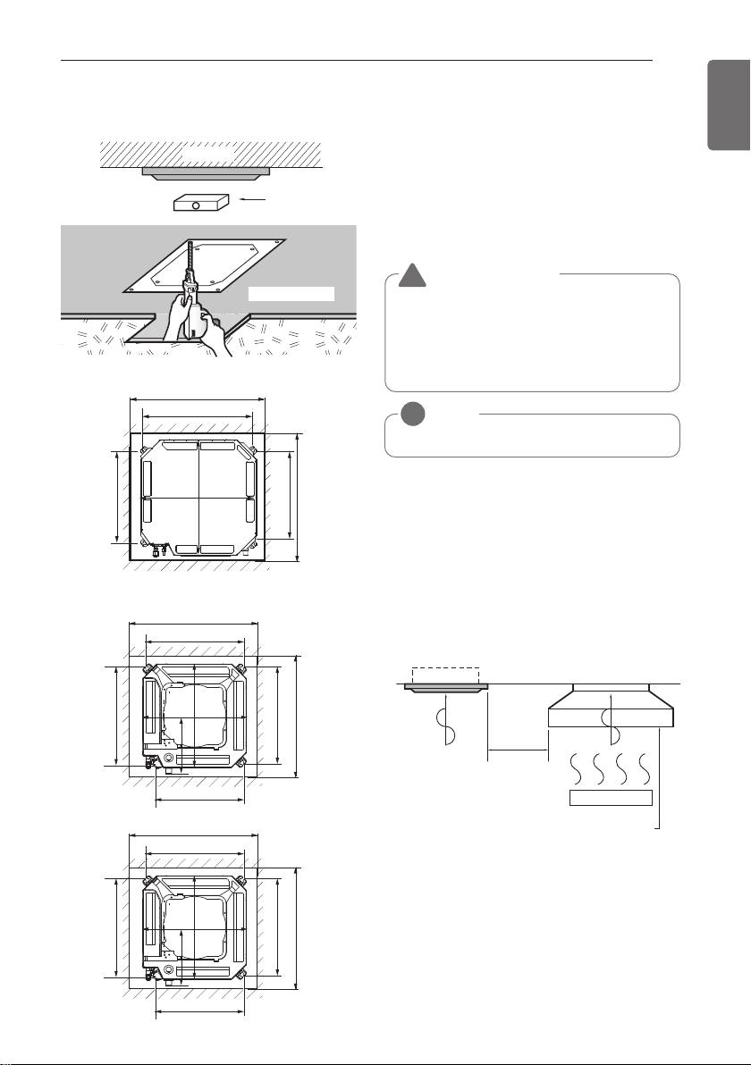
- Ensure the spaces indicated by arrows from the wall, ceiling, or other obstacles.
- The indoor unit must keep the maintenance space.
* Please use an annexed sheet or the
corrugated cardboard on the bottom of
packing as installation sheet.
* When using the bottom sheet, please use it
after separating the installation sheet from
packing of the product floor by using a knife
etc as a picture below.
Annexed sheet
Or
Packing corrugated
cardboard on the
bottom
Ceiling
Ceiling Board
500 or
more
1 000
or more
At least 10
At least 1 800
3 600 or less (TP)
Ceiling Board
800 or less
500 or
more
4 200 or less (TM/TN)
Floor
Unit : mm
300 or less
ENGLISH
7
THE INDOOR UNIT INSTALLATION
Level gauge
Ceiling
Ceiling board
875(Ceiling opening)
787
684
671
875(Ceiling opening)
840
840
Panel size : 950 X 950 mm
Panel size : 700 X 700 mm
585~660(Ceiling opening)
517
461
517
585~660(Ceiling opening)
523
570
570
319
Panel size : 620 X 620 mm
600(Ceiling opening)
517
461
517
600(Ceiling opening)
523
570
570
319
CAUTION
!
• This air-conditioner uses a drain pump.
• Install the unit horizontally using a level
gauge.
• During the installation, care should be
taken not to damage electric wires.
- Select and mark the position for fixing bolts
and piping hole.
- Decide the position for fixing bolts slightly
tilted to the drain direction after considering
the direction of drain hose.
- Drill the hole for anchor bolt on the wall.
NOTE
!
Avoid the following installation location.
1 Such places as restaurants and kitchen
where considerable amount of oil steam
and flour is generated. These may cause
heat exchange efficiency reduction, or
water drops, drain pump mal-function. In
these cases, take the following actions;
- Make sure that ventilation fan is enough
to cover all noxious gases from this place.
- Ensure enough distance from the cooking
room to install the air conditioner in such
a place where it may not suck oily steam.
2 Avoid installng air conditioner in such
places where cooking oil or iron powder is
generated.
3 Avoid places where inflammable gas is
generated.
4 Avoid place where noxious gas is
generated.
5 Avoid places near high frequency
generators.
Cooking table
Air conditioner
Take enough
distance
Use the ventilation fan for smoke-collecting
hood with sufficient capacity.
THE INDOOR UNIT INSTALLATION
[TM/TN/TP Chassis] (Unit:mm)
[TQ/TR Chassis] (Unit:mm)
8
ENGLISH
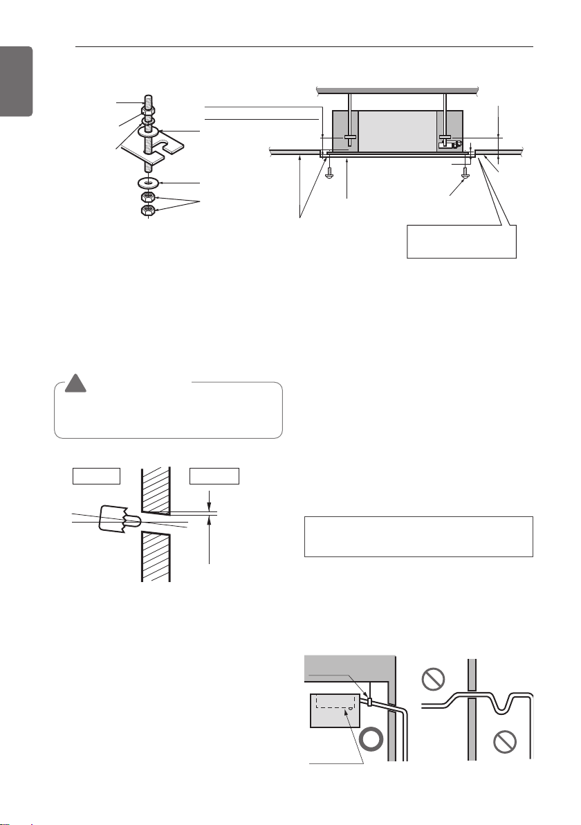
THE INDOOR UNIT INSTALLATION
The following parts is option.
① Hanging Bolt - W 3/8 or M10
② Nut - W 3/8 or M10
③ Spring Washer - M10
④ Plate Washer - M10
Drill the piping hole on the wall slightly tilted to the outdoor side using a Ø 70 hole-core drill.
CAUTION
!
Tighten the nut and bolt to prevent unit
falling.
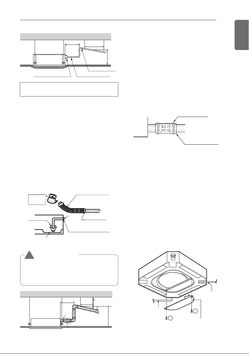
Maintenance
drain port
Upward
routing
not allowed
Pipe clamp
Indoor unit
Indoor Unit Drain Piping
- Drain piping must have down-slope (1/50 to
1/100): be sure not to provide up-and-down
slope to prevent reversal flow.
- During drain piping connection, be careful
not to exert extra force on the drain port on
the indoor unit.
- The outside diameter of the drain connection
on the indoor unit is 32 mm.
- Be sure to execute heat insulation on the
drain piping.
- Install the drain raising pipes at a right
angle to the indoor unit and no more than
300 mm from the unit.
Piping material: Polyvinyl chloride pipe
VP-25 and pipe fittings
Ceiling
Hanging bolt
(W 3/8 or M10)
(W 3/8 or M10)
Nut
Spring washer
(M10)
Wall
Indoor
Keep the length of the bolt
from the bracket to 40 mm
Flat washer for M10
(accessory)
Flat washer for M10
(accessory)
Nut
(W 3/8 or M10)
Outdoor
Ceiling board
Adjust the
same height
Air Conditioner body
Keep the length of 15~18 mm
between the air conditioner
bottom surface and the ceiling
surface
Paper model
for installation
Set screw of
paper model (4 pieces)
Open the ceiling board
along the outer edge of the
paper model
150 mm
Ceiling
board
5~7 mm
ENGLISH
9
THE INDOOR UNIT INSTALLATION
700 or less
1 -1.5 m
Clamp metal(attached) Drain hose(attached)
Drain raising pipe
300 mm or less300 mm or less300 mm or less
Heat insulation material: Polyethylene
foam with thickness more than 8 mm.
Drain test
The air conditioner uses a drain pump to drain
water.
Use the following procedure to test the drain
pump operation:
- Connect the main drain pipe to the exterior
and leave it provisionally until the test comes
to an end.
- Feed water to the flexible drain hose and
check the piping for leakage.
- Be sure to check the drain pump for normal
operating and noise when electrical wiring is
complete.
- When the test is complete, connect the
flexible drain hose to the drain port on the
indoor unit.
HEAT INSULATION
- Use the heat insulation material for the
refrigerant piping which has an excellent
heat-resistance (over 120 °C).
- Precautions in high humidity circumstance:
This air conditioner has been tested
according to the "KS Standard Conditions
with Mist" and confirmed that there is not
any default. However, if it is operated for a
long time in high humid atmosphere (dew
point temperature: more than 23 °C), water
drops are liable to fall. In this case, add heat
insulation material according to the following
procedure:
- Heat insulation material to be prepared...
Adiabatic EPDM or NBR with thickness 10 to
20 mm.
- Stick glass wool on all air conditioners that
are located in ceiling atmosphere.
Wiring Connection
- Open the control box cover and connect the
Remote controller cable and Indoor power
wires.
- Remove the control box cover for electrical
connection between the indoor and outdoor
unit. (Remove screws
①
)
- Use the cord clamper to fix the cord.
Remote
controller
cable
1
1
Connection
cord
between the
indoor unit and
the outdoor
unit
Control box cover
(On which the
Electric Wiring
Connection is put)
CAUTION
!
The supplied flexible drain hose should not
be curved, neither screwed. The curved or
screwed hose may cause a leakage of
water.
Flexible drain hose
Feed
water
Drain Pump
(accessory)
Main
drain pipe
Drain
Glue the joint
port
Drain hose connection
Use the clip (accessory)
Drain pan
Indoor
unit
Fastening band
(accessory)
Refrigerant
piping
Thermal insulator
(accessory)
Max 300 mm
Metal
clamp
Insulation
Hanger
distance
Hanger Bracket
1~15 m
1/50~1/100 slope
Flexible drain hose
Max 700 mm
10
ENGLISH
THE INDOOR UNIT INSTALLATION
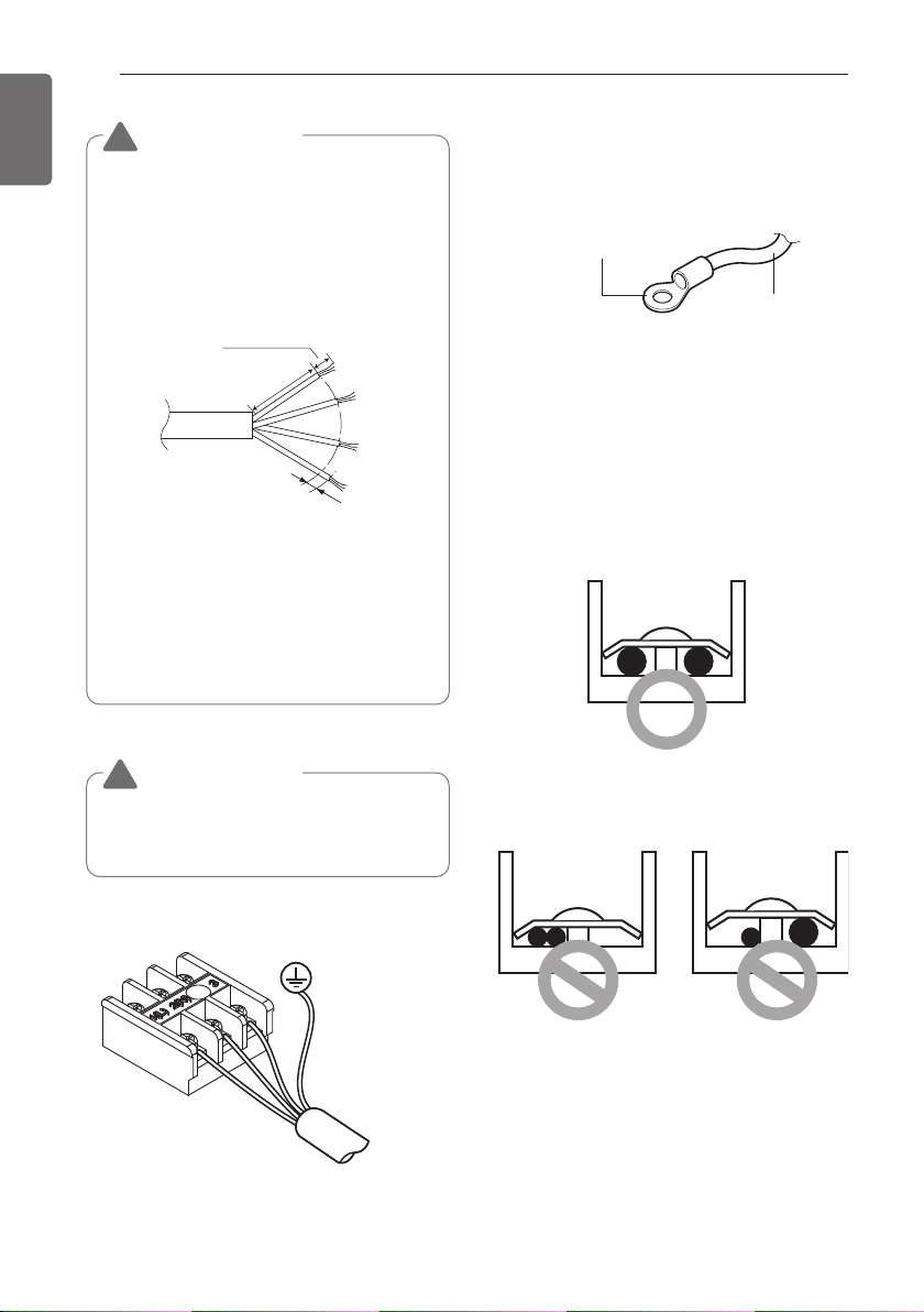
Precautions when laying power
wiring
Use round pressure terminals for connections
to the power terminal block.
When none are available, follow the
instructions below.
- Do not connect wiring of different
thicknesses to the power terminal block.
(Slack in the power wiring may cause
abnormal heat.)
- When connecting wiring which is the same
thickness, do as shown in the figure below.
CAUTION
!
The connecting cable connected to the
indoor and outdoor unit should be
complied with the following specifications
(This equipment shall be provided with a
cable set complying with the national
regulation). (Rubber insulation, type
H05RN-F approved by HAR or SAA).
CAUTION
!
The Power cable connected to the unit
should be selected according to the
following specifications.
If the supply cable is damaged, it must be
replaced by a special cable or assembly
available from the manufacturer of its
service agent.
NORMAL
CROSS-SECTIONAL
AREA 0.75 mm
2
20 mm
35±5 mm
GN/YL
10±3 mm
Power wirer
Round pressure terminal
Connect same thickness
wiring to both sides.
It is forbidden to
connect two to one
side.
It is forbidden to
connect wiring of
different thicknesses.
- For wiring, use the designated power wire
and connect firmly, then secure to prevent
outside pressure being exerted on the
terminal block.
- Use an appropriate screwdriver for tightening
the terinal screws. A screwdriver with a
small head will strip the head and make
proper tighterning impossible.
- Over-tightening the terminal screws may
break them.
ENGLISH
11
OPERATING INSTRUCTION
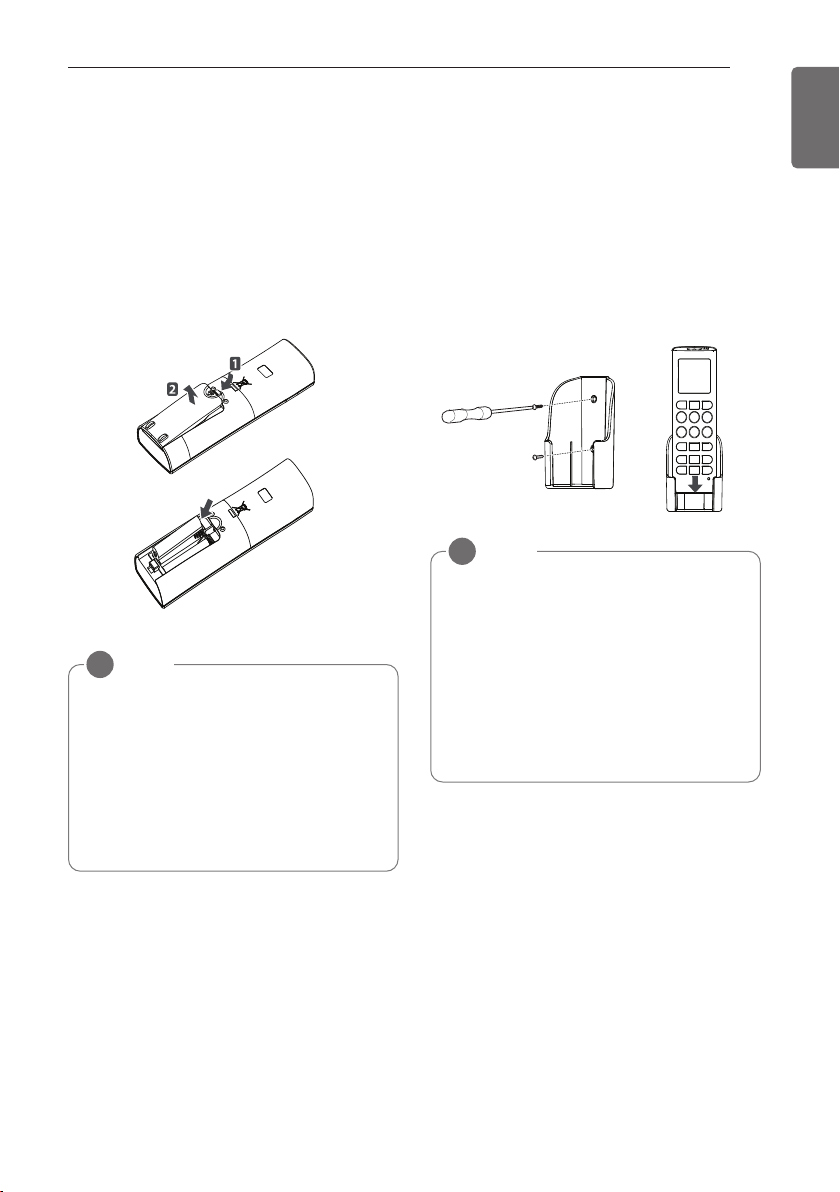
How to insert the Batteries
1 Remove the battery cover by pulling it
according to the arrow direction.
2 Insert new batteries making sure that the
(+) and (-) of battery are installed correctly.
3 Reattach the cover by sliding it back into
position.
Wireless Remote Controller
Maintenance
1 Choose a suitable place where its safe &
easy to reach.
2 Fix the holder to wall etc with the supplied
screws firmly.
3 Slide the remote controller inside the
holder.
Operating Method
1 The signal receiver is inside the unit.
2 Aim the remote controller towards the unit
to operate it. There should not be any
blockage in between.
NOTE
!
• Always use/replace both batteries of
same type.
• If the system is not to be used for a
long time, remove the batteries to save
their working life.
• If the display screen of remote
controller starts, fading replace both of
the batteries.
NOTE
!
• Remote controller should never be
exposed to direct sunlight.
• Signal transmitter & receiver should
always be clean for proper
communication. Use a soft cloth to
clean them.
• In case some other appliances also get
operated with remote control, change
their position or consult your
serviceman.
OPERATING INSTRUCTION
 Loading...