

LG ATNH24GPLE2, ATNH42GMLE2, AUUW24GD2, AUUW42GD2 User Manual
SINGLE ZONE
Heat pump 60Hz/R410A
6CSL0-01B (Replaces 6CSL0-01A)

SINGLE ZONE
• General Information
• Indoor Units
• Outdoor Units
• Design and installation

SINGLE ZONE
Introduction
Preface
New era brings more sophisticated and advanced buildings which in turn demands specialized and optimized direct expan-
sion air conditioning systems. Also energy efficiency, environment friendly, low noise and low maintenance cost are the fea-
tures which are essential for these systems.
As a part of vertical integration LG makes all the key components in house, which gives an edge to LG to make better and
latest technology products with best quality in optimized time.
SINGLE ZONE systems with are equipped with DC inverter technology and R410A refrigerant is perfect solution to various
installation locations.
LG SINGLE ZONE system consists of a single common outdoor unit for single indoor unit, such as ceiling cassette.
This Engineering product data book incorporates information about the product itself, its installation and designing for
SINGLE ZONE system.
The comprehensive study of this book will improve your knowledge about the system and its application in details.
LG Electronics Inc.
Air Conditioning & Energy Solution Company

SINGLE ZONE
Step by step
SINGLE ZONE
system selection process (reference)
(1)
Calculate or obtain the maximum heat load for the area(s) to be air conditioned
(2)
(3)
(4)
1. Air conditioners should not be installed in areas where corrosive gases, such as acid gas
or alkaline gas, are produced.
2. If the outdoor unit is installed close to the sea shore, direct exposure to the sea breeze
should be avoided and choose an outdoor unit with anti-corrosion treatment.
CAUTION
Selection of the control system
Control wiring method
Description of devices
Electrical wiring
Electrical characteristics
Field wiring
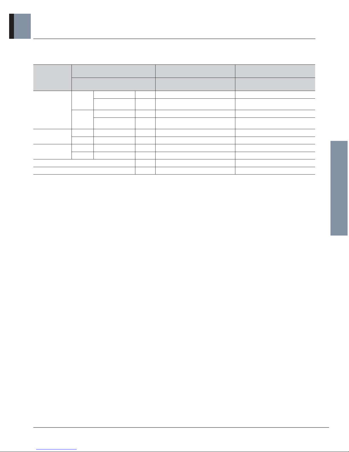
Indoor unit specifications
Outdoor unit specifications
Capacity coefficient factor
Air flow and temperature distributions

SINGLE ZONE
Part 1 General information
1. Model Line up
2. Nomenclature
3. Individual Control System
General Information of
Outdoor Units
SINGLE ZONE
Heat pump 60Hz/R410A _ 1
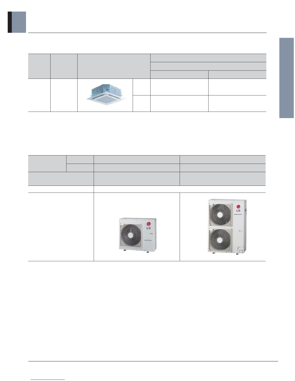
1. Model Line up
1.1 Indoor Units
1.2 Outdoor Units
Nominal Capacity
Btu/h 24,000 42,000
kW 7.03 12.3
Model Names
AUUW24GD2
[LUU247HV]
AUUW42GD2
[LUU427HV]
Power supply 208/230V, 1Ø, 60Hz
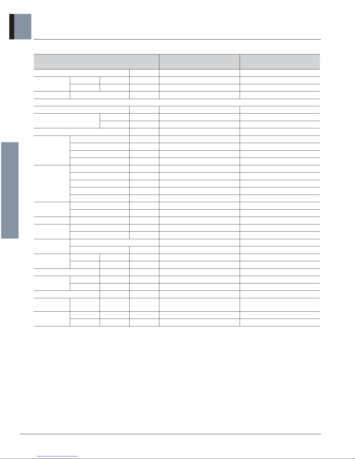
Chassis
Category Type Chassis
Model Name
Capacity, Btu/h(kW)
24,000 (7.03) 42,000 (12.3)
Ceiling
cassette
4way
TP
ATNH24GPLE2
[LCN247HV]
TM
ATNH42GMLE2
[LCN427HV]
General Information of
Outdoor Units
SINGLE ZONE
2 _ Heat pump 60Hz/R410A
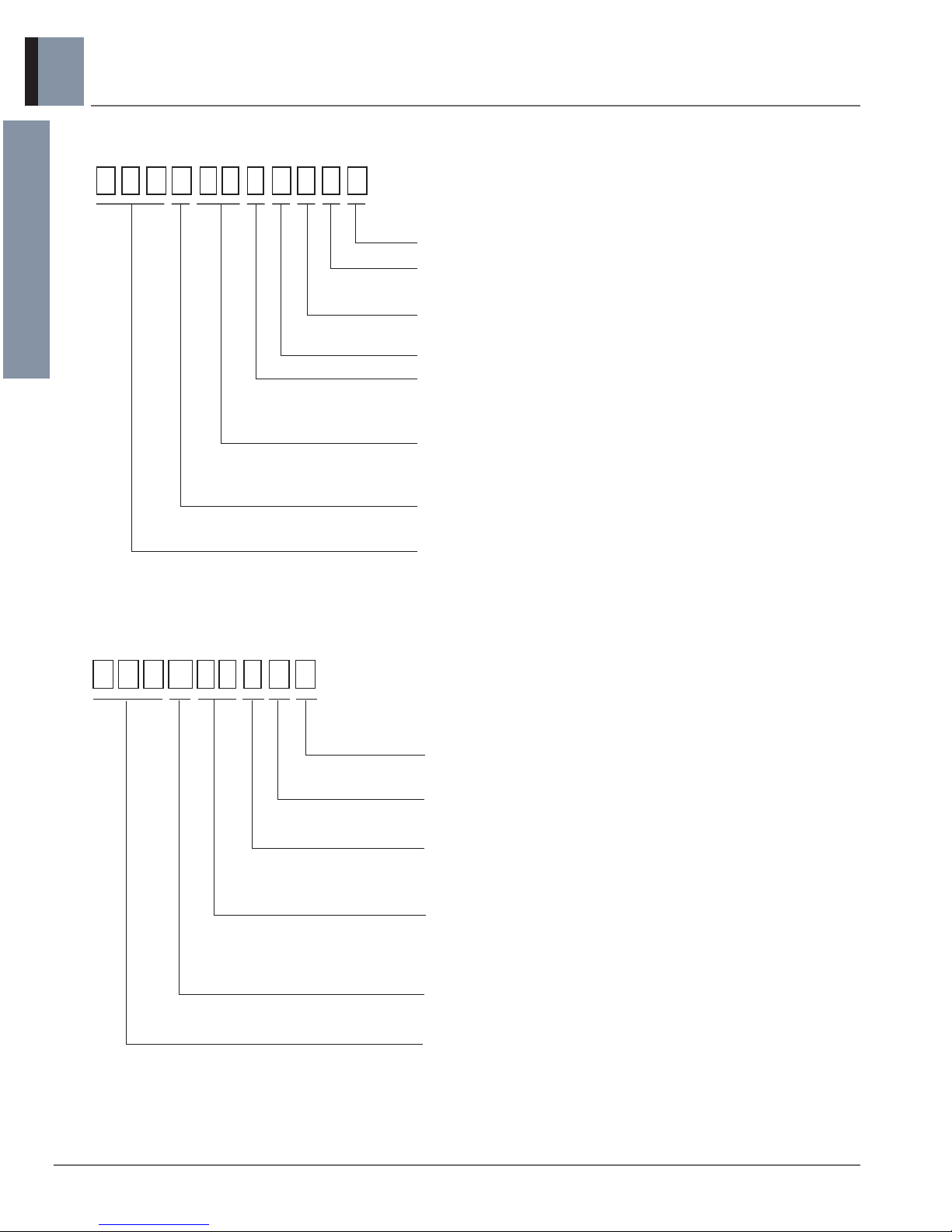
2. Nomenclature
A T N H 2 4 G P L E 2
Serial number
Functions
E : Elevation grille
Look
L : Basic
Chassis name
Electric ratings (Volts, Phase, Freq)
G : 220-240V, 1Ø, 50Hz
208/230V, 1Ø, 60Hz
Nominal cooling capacity in kBtu/h
24 : 24kBtu/h
42 : 42kBtu/h
Model type
H : Heat Pump
Indicates that this is a indoor unit for R410A
ATN : Ceiling cassette type indoor unit
A U U W 2 4 GD2
Model Type
D : Standard Inverter
Serial number
Electric ratings (Volts, Phase, Freq)
G : 220-240V, 1Ø, 50Hz
208/230V, 1Ø, 60Hz
Indicates that this is a
R410A outdoor unit
SINGLE ZONE
Model type
W : Inverter heat pump
Nominal cooling capacity in kBtu/h
24 :
42 :
24kBtu/h
42kBtu/h
2.1 Indoor Units (Global)
2.2 Outdoor Units (Global)

General Information of
Outdoor Units
SINGLE ZONE
Heat pump 60Hz/R410A _ 3
3. Individual Control System
3.1 Control systems (standard)
These controllers will be provided with the respective indoor units.
Type Individual controller Applicable model
Wired remote controller Ceiling cassette
PQRCVSL0QW

SINGLE ZONE
Part 2 Product data
n Indoor units
n Outdoor units

SINGLE ZONE
n Indoor units
Ceiling cassette 4-way
1.1 List of functions
1.2 Specifications
1.3 Dimensions
1.4 Piping diagrams
1.5 Wiring Diagrams
1.6 Air flow and temperature distributions (reference data)
1.7 Sound levels
1.8 Controller

Indoor Units
Heat pump 60Hz/R410A _ 1
1. Ceiling cassette 4-way
SINGLE ZONE
Note
1. * : These functions need to connect the wired remote controller.
O : Applied X : Not applied
Accessory model name : Installed at field, ordered and purchased separately by the corresponding model name, supplied with separate package.
Category Functions
ATNH24GPLE2 [LCN247HV]
ATNH42GMLE2 [LCN427HV]
Air flow
Air supply outlet 4
Airflow direction control (left & right) X
Airflow direction control (up & down) Auto
Auto swing (left & right) X
Auto swing (up & down) O
Airflow steps (fan/cool/heat) 4 / 5 / 4
Chaos wind(auto wind) O
Jet cool/heat O / X
Swirl wind O
Air purifying
Triple filter (Deodorizing) X
Plasma air purifier PTPKM0
Allergy Safe filter X
Long-life prefilter (washable / anti-fungus) O
Installation
Drain pump O
E.S.P. control* X
Electric heater X
High ceiling operation* O
Auto Elevation Grille* PTEGM0
Reliability
Hot start O
Self diagnosis O
Soft dry operation O
Convenience
Auto changeover O
Auto cleaning X
Auto operation(artificial intelligence) X
Auto Restart O
Child lock* O
Forced operation O
Group control* O
Sleep mode O
Timer(on/off) O
Timer(weekly)* O
Two thermistor control* O
Individual
control
Wired remote controller O
Deluxe wired remote controller PQRCUDS0 / PQRCUDS0B / PQRCUDS0S
Simple wired remote controller PQRCVCL0Q / PQRCVCL0QW
Simple Wired remote controller(for hotel use)
PQRCHCA0Q / PQRCHCA0QW
Wireless remote controller PQWRHDF0
CAC network
function
General central controller (Non LGAP) X
Network Solution(LGAP) O
Dry contact PQDSA(1) / PQDSB(1)/PQDSBC / PQDSBNGCM1
PI 485(for Indoor Unit) X
Special
function kit
Zone controller X
CTI(Communication transfer interface) X
Electronic thermostat X
Others
Remote temperature sensor PQRSTA0
Telecom shelter controller X
1.1 List of functions

Indoor Units
2 _ Heat pump 60Hz/R410A
1. Ceiling cassette 4-way
SINGLE ZONE
1.2 Specifications
Notes :
1. Wiring cable size must comply with the applicable local and national code.
2. Due to our policy of innovation some specifications may be changed without notification.
3. Sound Level Values are measured at Anechoic chamber.
Therefore, these values can be increased owing to ambient conditions during operation.
4. Acceptable operating voltage: 187V-253V
Model Name
ATNH24GPLE2
[LCN247HV]
ATNH42GMLE2
[LCN427HV]
Power Supply V, Ø, Hz
Power Input W
Running Current A
Casing Color -
Dimensions Body
W x H x D mm
W x H x D inch
Net Weight Body kg (lbs)
Heat
Exchanger
(Row x Column x Fins per
inch) x No.
-
Face Area m2(ft2)
Fan
Type -
Air Flow Rate
H / M / L m3/min
H / M / L ft3/min
Fan Motor
Type Output W x No.
Dehumidification Rate
l
/h (pts/h)
Sound Pressure Level H / M / L dB(A)
Sound Power Level dB(A)
Piping
Connections
Liquid mm(inch)
Gas mm(inch)
Drain (O.D. / I.D.) mm(inch)
Safety Devices
-
-
Power and Communication Cable (included Earth) No. x mm2(AWG)
Decoration Panel
Model Name Casing Color -
Dimensions
W x H x D mm
W x H x D inch
Net weight kg (lbs)
208/230, 1, 60
60
0.60
-
840 × 204 × 840
33-1/16 x 8-1/32 x 33-1/16
20.5 (45.2)
(2 x 8 x 19) x 1
0.35 (3.77)
Turbo Fan
17.0 / 15.0 / 13.0
600 / 530 / 459
BLDC
60 x 1
2.4 (5.1)
38 / 36 / 34
57
Ø 9.52 (3/8)
Ø 15.88 (5/8)
Ø
32.0(1-1/4) / 25.0(31/32)
Fuse
Thermal Protector for Fan Motor
4C x 0.75 (18)
PT-UMC
Morning Fog
950 × 25 × 950
37-13/32 x 31/32 x 37-13/32
5.0 (11.0)
208/230, 1, 60
120
1.00
-
840 × 288 × 840
33-1/16 x 11-11/32 x 33-1/16
24.6 (54.2)
(2 x 12 x 21) x 1
0.53 (5.65)
Turbo Fan
30.0 / 28.0 / 26.0
1,060 / 989 / 918
BLDC
124 x 1
3.6 (7.7)
46 / 44 / 40
65
Ø 9.52 (3/8)
Ø 15.88 (5/8)
Ø
32.0(1-1/4) / 25.0(31/32)
Fuse
Thermal Protector for Fan Motor
4C x 0.75 (18)
PT-UMC
Morning Fog
950 × 25 × 950
37-13/32 x 31/32 x 37-13/32
5.0 (11.0)
Indoor Units
Heat pump 60Hz/R410A _ 3
1. Ceiling cassette 4-way
SINGLE ZONE
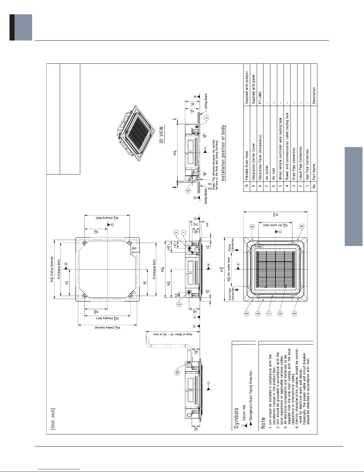
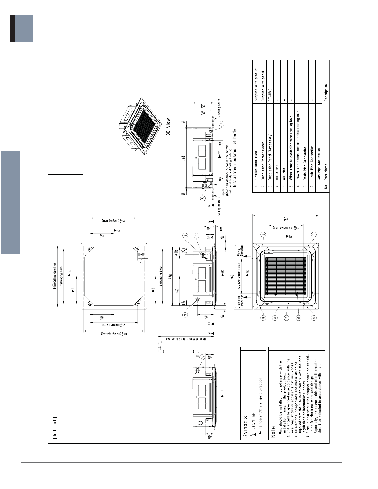
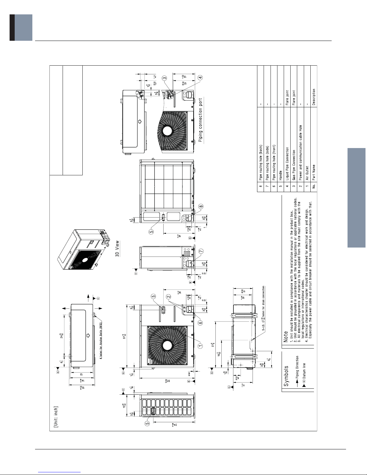
1.3 Dimensions
TP Chassis
ATNH24GPLE2 [LCN247HV]
Indoor Units
4 _ Heat pump 60Hz/R410A
1. Ceiling cassette 4-way
SINGLE ZONE
TM Chassis
ATNH42GMLE2 [LCN427HV]
Indoor Units
Heat pump 60Hz/R410A _ 5
1. Ceiling cassette 4-way
SINGLE ZONE
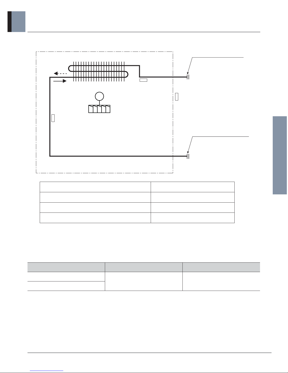
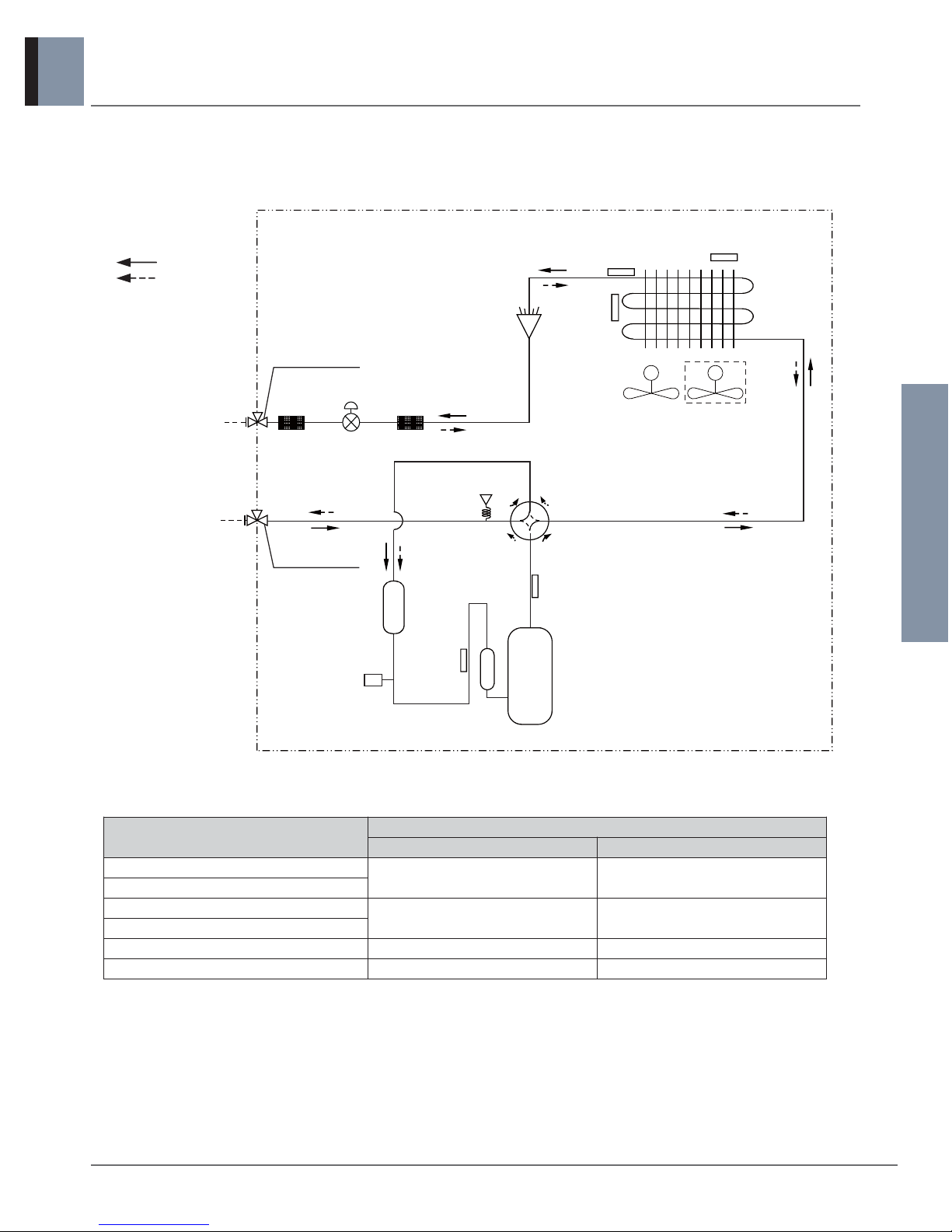
1.4 Piping diagrams
Heat exchanger
Gas pipe connection port
(flare connection)
Liquid pipe connection port
(flare connection)
Turbo fan
Cooling
Heating
M
Thermistor for
suction air
temperature
Thermistor for
Evaporator
outlet temperature
Thermistor for
Evaporator inlet
temperature
n Refrigerant pipe connection port diameters
[Unit:mm(inch)]
Description PCB Connector
Thermistor for suction air temperature CN-ROOM
Thermistor for evaporator inlet temperature CN-PIPE / IN
Thermistor for evaporator outlet temperature CN-PIPE / OUT
Model Gas Liquid
ATNH24GPLE2 [LCN247HV]
Ø15.88(5/8) Ø9.52(3/8)
ATNH42GMLE2 [LCN427HV]
Indoor Units
6 _ Heat pump 60Hz/R410A
1. Ceiling cassette 4-way
SINGLE ZONE
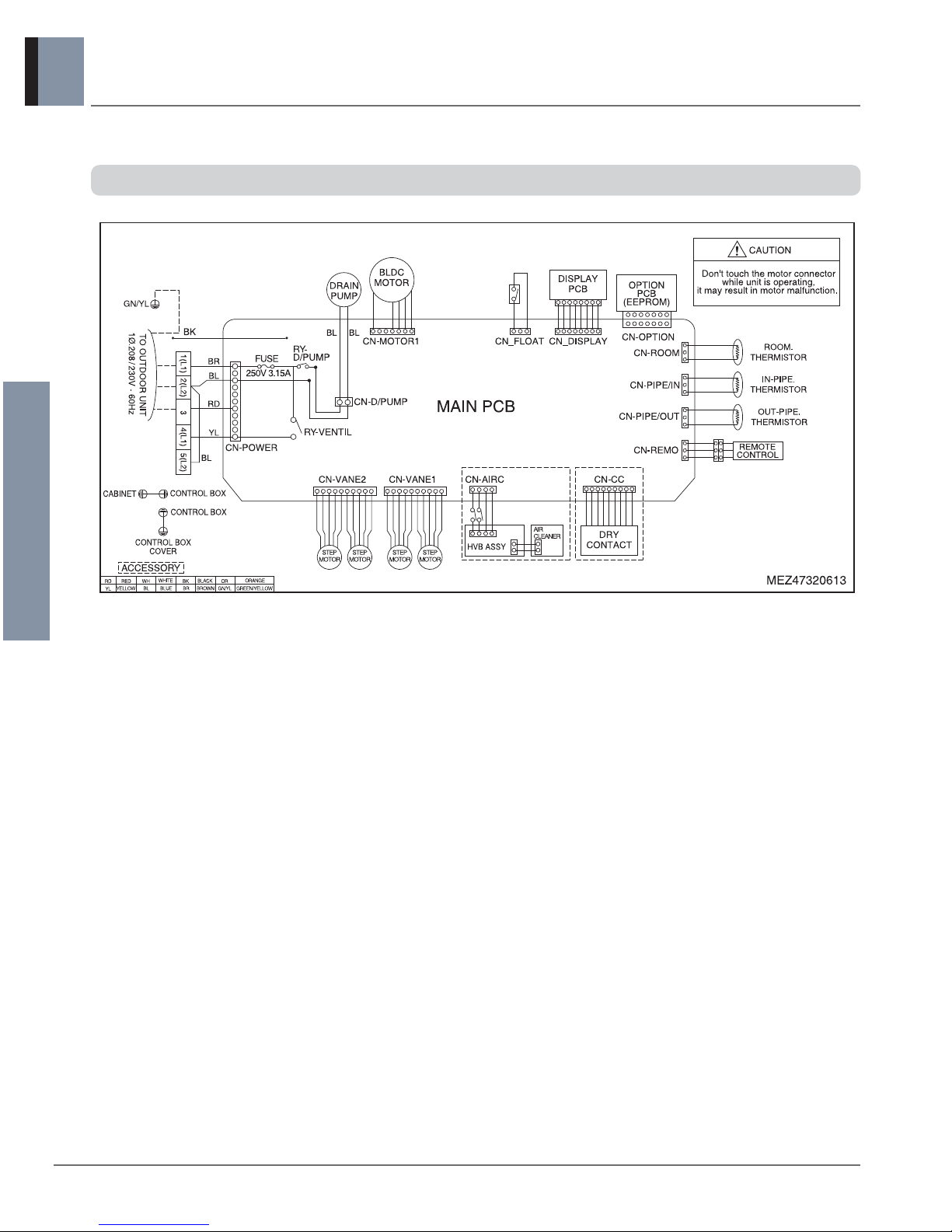
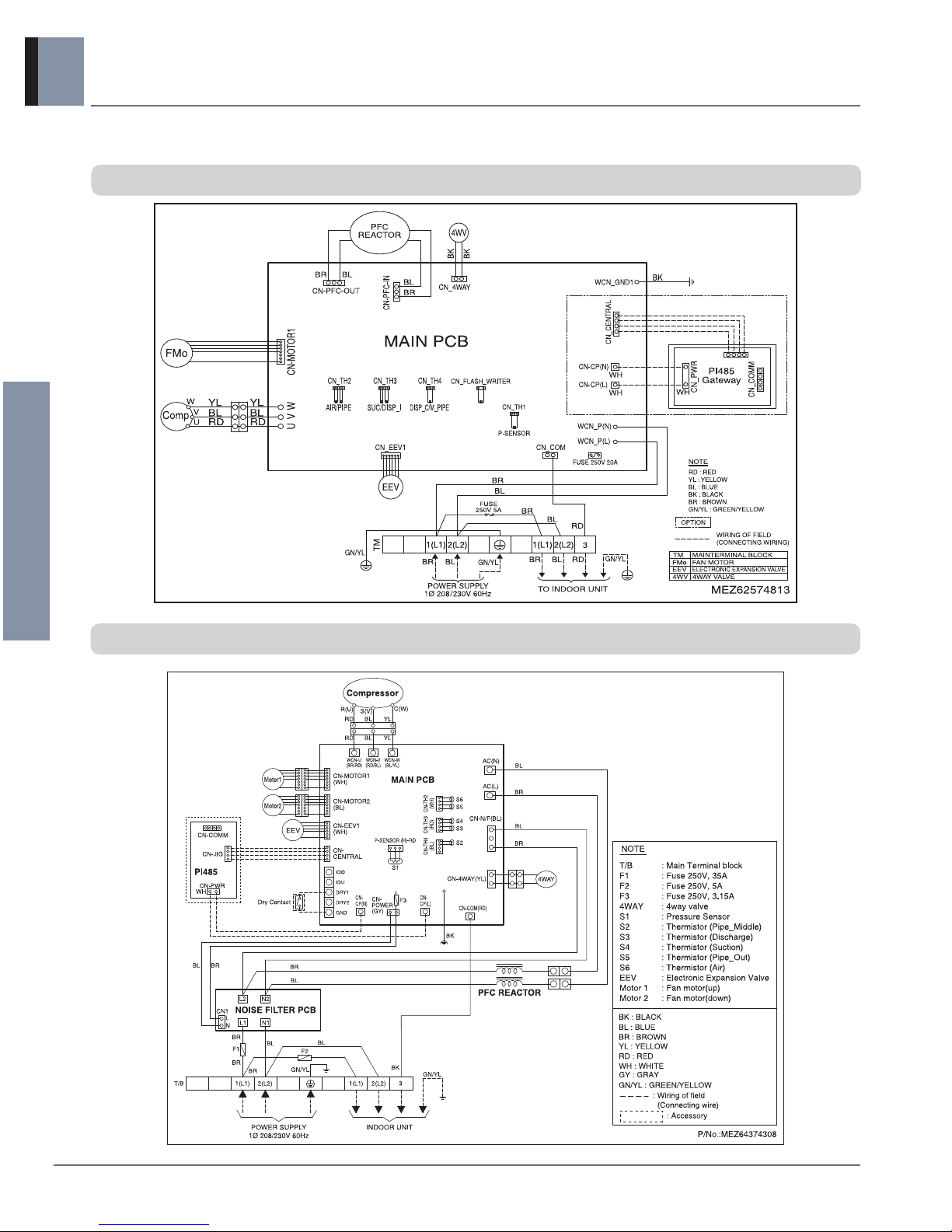
Models : ATNH24GPLE2 [LCN247HV] / ATNH42GMLE2 [LCN427HV]
1.5 Wiring diagrams
Indoor Units
Heat pump 60Hz/R410A _ 7
1. Ceiling cassette 4-way
SINGLE ZONE
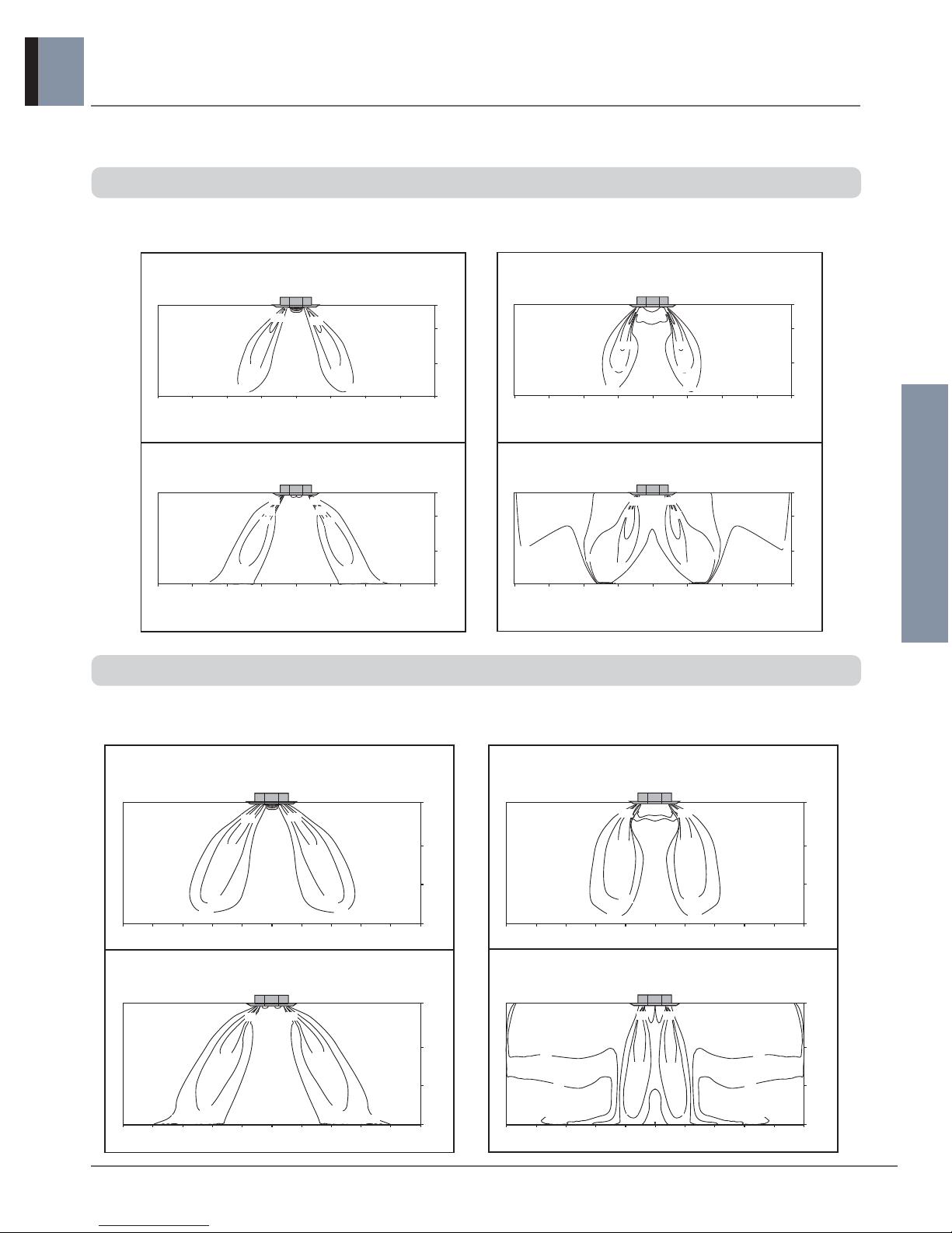
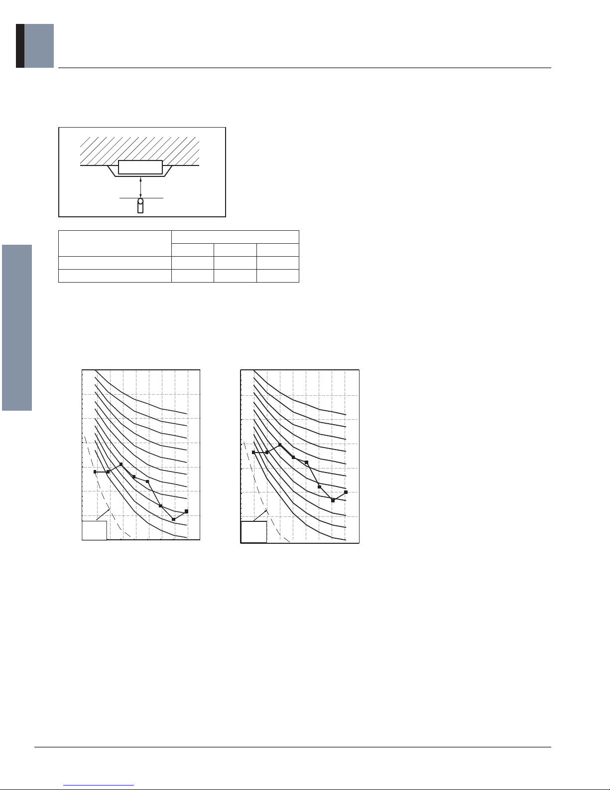
Models : ATNH24GPLE2 [LCN247HV]
Cooling Heating
Discharge angle: 40°
Air velocity [ft/s]
Teftperature [°F]
9ft
7ft
3ft
0ft
13ft10ft10ft13ft 7ft7ft 3ft3ft 0ft
9ft
7ft
3ft
13ft10ft10ft13ft 7ft7ft 3ft3ft 0ft
9ft
7ft
3ft
0ft
13ft10ft10ft13ft 7ft7ft 3ft3ft 0ft
9ft
7ft
3ft
0ft
13ft10ft10ft13ft 7ft7ft 3ft3ft 0ft
6.6
6.6
4.6
4.6
3.3
3.3
Discharge angle: 50°
Air velocity [ft/s]
Teftperature [°F]
91
91
86
86
81
81
75
75
72
72
75
75
6.6 6.6
3.3
3.3
1.6
1.6
68
6464
68
72
72
73
73
1.6 Air flow and temperature distributions (reference data)
Models : ATNH42GMLE2 [LCN427HV]
Cooling Heating
Discharge angle: 40°
Air velocity [ft/s]
Teftperature [°F]
13.1
13.1
9.8
9.8
6.6
6.6
3.3
3.3
Discharge angle: 50°
Air velocity [ft/s]
Teftperature [°F]
10.5ft
0ft
13ft 16ft10ft16ft 7ft3ft3ft 0ft
7ft
3ft
10ft 7ft13ft
10.5ft
13ft 16ft10ft16ft 7ft3ft3ft 0ft
7ft
3ft
10ft 7ft13ft
10.5ft
13ft 16ft10ft16ft 7ft3ft3ft 0ft
7ft
3ft
10ft 7ft13ft
10.5ft
13ft 16ft10ft16ft 7ft3ft3ft 0ft
7ft
3ft
10ft 7ft13ft
75
91
91
75
81
81
86
86
72
72
13.113.1
9.8
9.8
6.6
6.6
3.3
3.3
64
64
68
68
72
72
75
75
Indoor Units
8 _ Heat pump 60Hz/R410A
1. Ceiling cassette 4-way
SINGLE ZONE
1.7 Sound levels
4.9ft
Ceiling
Octave Band Center Frequency (Hz)
Octave Band Sound Pressure Level (0dB = 20μPa)
10
20
30
40
50
60
70
80
63 125 250 500 1000 2000 4000 8000
NC-15
NC-20
NC-25
NC-30
NC-35
NC-40
NC-45
NC-50
NC-55
NC-60
NC-65
Approximate
Hearing
Threshold
Octave Band Center Frequency (Hz)
Octave Band Sound Pressure Level (0dB = 20μPa)
10
20
30
40
50
60
70
80
63 125 250 500 1000 2000 4000 8000
NC-15
NC-20
NC-25
NC-30
NC-35
NC-40
NC-45
NC-50
NC-55
NC-60
NC-65
Approximate
Hearing
Threshold
Overall
Sound pressure level
ATNH24GPLE2 [LCN247HV] ATNH42GMLE2 [LCN427HV]
Notes:
- Sound measured at 4.9ft away from the center of the unit.
- Data is valid at free field condition.
- Data is valid at nominal operation condition.
- Reference accoustic pressure 0dB=20μPa.
- Sound level will vary depending on a range of factors such as
the construction(acoustic absorption coefficient) of particular
room in which the equipment is installed.
- The operating conditions are assumed to be standard.
Model
Sound pressure Levels [dB(A)]
H M L
ATNH24GPLE2 [LCN247HV]
38 36 34
ATNH42GMLE2 [LCN427HV]
46 44 40
Indoor Units
Heat pump 60Hz/R410A _ 9
1. Ceiling cassette 4-way
SINGLE ZONE
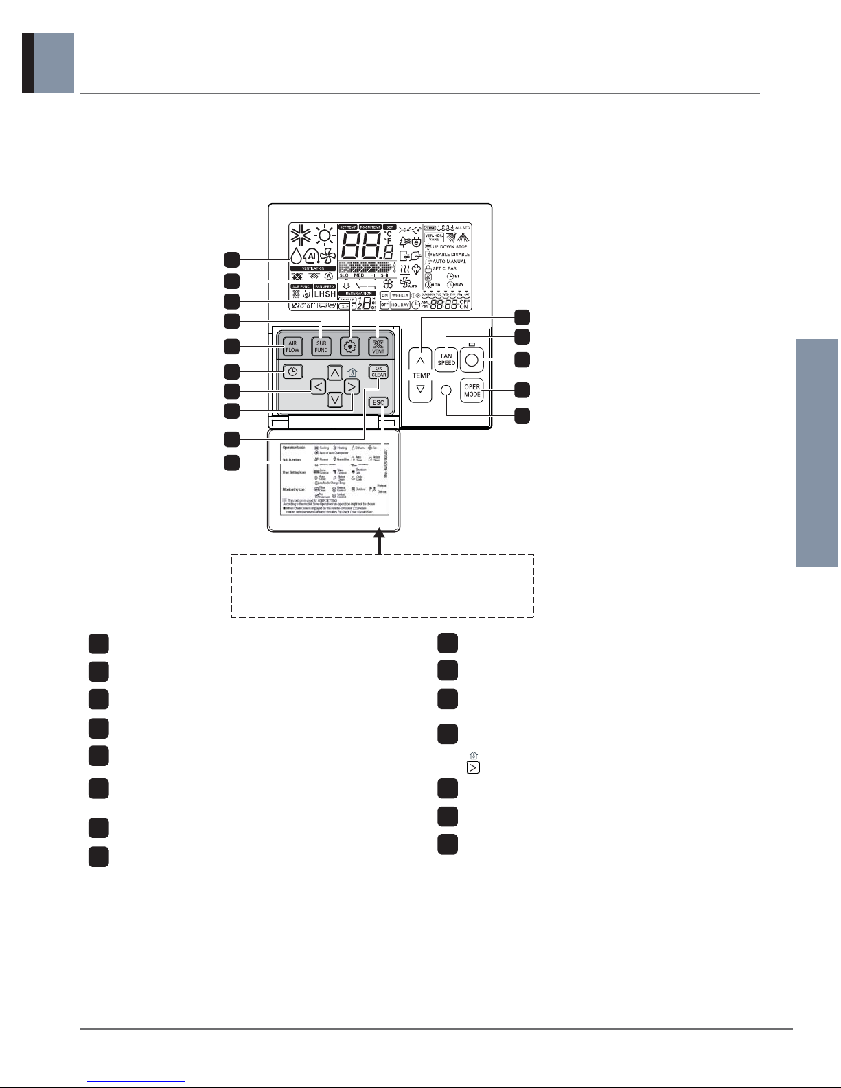
1.8 Controller
Wired remote controller
Model name :
PQRCVSL0QW (White Color_Supplied) / PQRCVSL0 (Black Color_Accessory)
Note :
h Display temperature can be different from actual room temperature if the remote controller is installed at the place where
sun-rays are falling directly or the place nearby heat source.
h The actual product can be different from above contents depending upon model type.
h When using simultaneous operation system, whenever press remote controller button, system will approximately operate
after 1~2 minutes.
1
4
5
7
11
10
9
8
2
3
6
13
12
Please attach the inform label inside of the door.
Please choose proper language depend on your
country.
14
15
OPERATION INDICATION SCREEN
SET TEMPERATURE Button
FAN SPEED Button
ON/OFF Button
OPRATION MODE SELECTION Button
WIRELESS REMOTE CONTROLLER RECEIVER
• Some products don't receive the wireless signals.
AIR FLOW Button
SUBFUNCTION Button
FUNCTION SETTING Button
VENTILATION Button
RESERVATION
UP,DOWN,LEFT,RIGHT Button
• To check the indoor temperature, press
button.
ROOM TEMPERATURE Button
SETTING/CANCEL Button
EXIT Button
1
2
3
4
5
6
7
8
9
10
11
12
13
14
15
h
Some functions may not be operated and displayed depending on the product type.

SINGLE ZONE
n Outdoor units
DC Inverter SINGLE ZONE
1. Power supply
2. List of functions
3. Specifications
4. Dimensions
5. Piping diagrams
6. Wiring diagrams
7. Capacity tables
8. Capacity coefficient factor
9. Operation range
10. Electrical characteristics
11. Field wiring diagram
12. Sound levels
Outdoor Units
Heat pump 60Hz/R410A _ 1
1. DC Inverter SINGLE ZONE
SINGLE ZONE
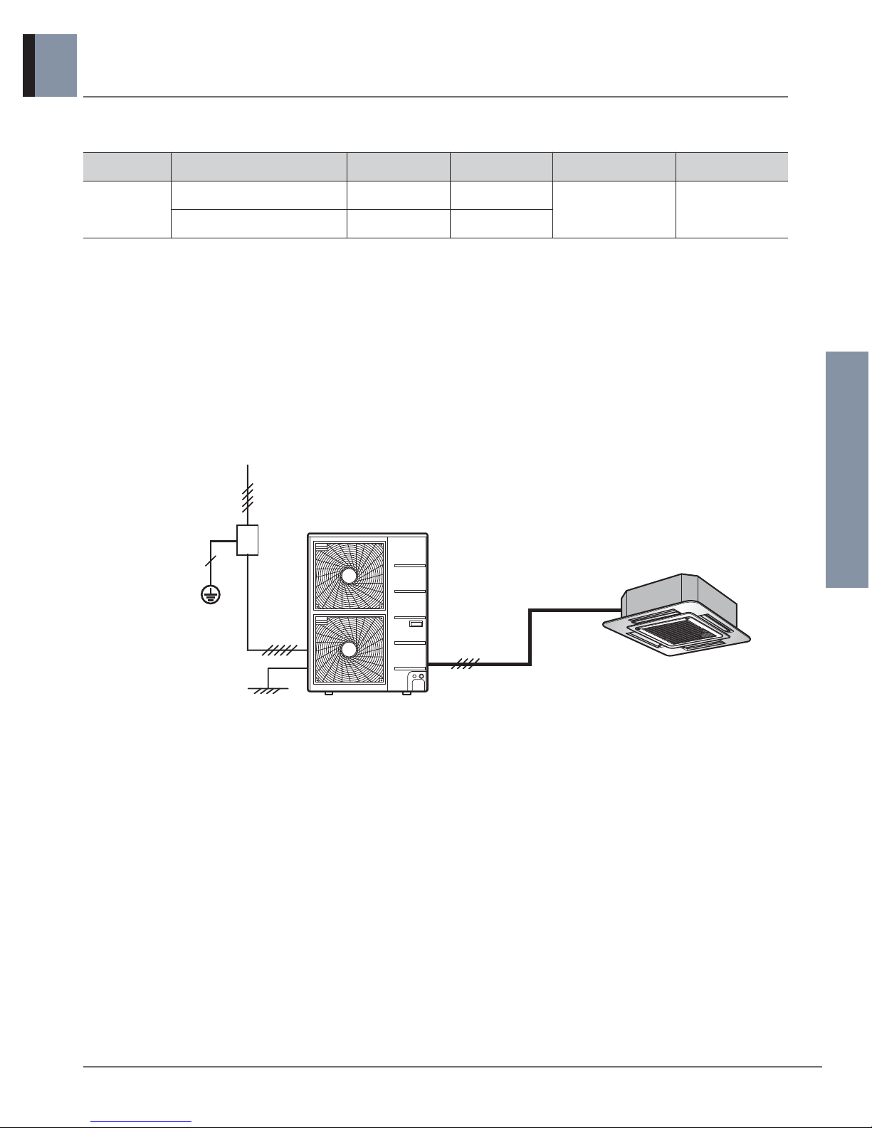
1.1 Power supply
External wiring procedure
- The power supply work is needed only to the outdoor unit. The power supply to the BD unit and the indoor unit is
conducted through the communication wiring. Therefore, the power supply work can be carried out at just one place of the
outdoor unit. It will simplify the work procedure and save cost.
- Wiring cable size must comply with the applicable local and national codes.
Circuit breaker
Earth
Power supply
Outdoor unit
Type Outdoor unit
Capacity (kBtu/h)
Circuit breaker
capacity
Power supply Voltage range
1Phase
Inverter
AUUW24GD2 [LUU247HV] 24.0 30A
208/230V, 1Ø, 60Hz
MIN.:187
MAX.:253
AUUW42GD2 [LUU427HV] 42.0 40A
Outdoor Units
2 _ Heat pump 60Hz/R410A
1. DC Inverter SINGLE ZONE
SINGLE ZONE
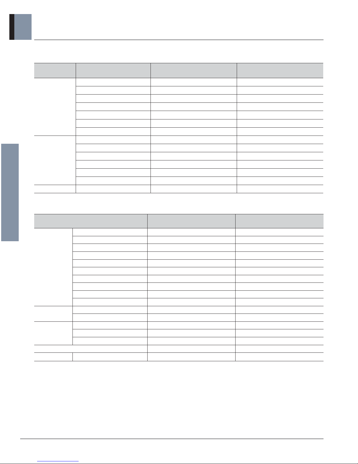
1.2 List of functions
[Note]
• O: Applied, • X: Not applied
Accessory model name : Installed at field, ordered and purchased separately by the corresponding model name, supplied with separate
package.
Device
AUUW24GD2
[LUU247HV]
AUUW42GD2
[LUU427HV]
Central
Controller
Simple Controller
Function controller
Function Scheduler
AC Ez
AC Smart ll
Option Kit (SD card type)
ACP(Advanced Control Platform)
AC Manager
PI485
DO(Digital Output) Kit
BNU (Building
Network Unit)
LONWORKS Gateway
BACnet Gateway
Installation
Y branch
Header branch
Air Guide
ODU Dry Contact
Low Ambient Kit
Category Functions
AUUW24GD2
[LUU247HV]
AUUW42GD2
[LUU427HV]
Reliability
Defrost / Deicing O O
High pressure switch X X
Low pressure switch X X
Phase protection X X
Restart delay (3-minutes) O O
Self diagnosis O O
Soft start O O
Convenience
Test function X X
Night Silent Operation O O
Wiring Error Check X X
Peak Control O O
Mode Lock O O
Forced Operation (Outdoor Unit) O O
Network function Network soluation(LGAP) O O
X
X
X
PQCSZ250S0
PQCSW320A1E
PQCSE341A0 / PQCSE342A0
PQCPA11A0E / PQCPB11A0E
X
PMNFP14A0/PMNFP14A1
PQNFP00T0
PQNFB16A1
PQNFB17B0
X
X
X
X
O (Logical operation)
X
X
X
PQCSZ250S0
PQCSW320A1E
PQCSE341A0 / PQCSE342A0
PQCPA11A0E / PQCPB11A0E
X
PMNFP14A0/PMNFP14A1
PQNFP00T0
PQNFB16A1
PQNFB17B0
X
X
X
PQDSBCDVM0
O (Logical operation)
Outdoor Units
Heat pump 60Hz/R410A _ 3
1. DC Inverter SINGLE ZONE
SINGLE ZONE
1.3 Specifications
Note :
1. All data are based on the following conditions:
- Cooling Temperature : Indoor 27°C(80.6°F) DB / 19°C(66.2°F) WB
Outdoor 35°C(95°F) DB / 24°C(75.2°F) WB
- Heating Temperature : Indoor 20°C(68°F) DB / 15°C(59°F) WB
Outdoor 7°C(44.6°F) DB / 6°C(42.8°F) WB
- Piping Length : Interconnected Pipe Length = 7.6m(25ft)
- Difference Limit of Elevation (Outdoor ~ Indoor Unit) is Zero.
2. Due to our policy of innovation some specifications may be changed without notification.
Combination
Outdoor unit
AUUW24GD2
[LUU247HV]
AUUW42GD2
[LUU427HV]
Indoor unit
ATNH24GPLE2
[LCN247HV]
ATNH42GMLE2
[LCN427HV]
Capacity
Cooling
Min.∼Rated∼Max.
kW 2.84 ~ 7.03 ~ 7.81 5.00 ~ 12.3 ~ 13.8
Min.∼Rated∼Max.
Btu/h 9,700 ~ 24,000 ~ 26,700 17,100 ~ 42,000 ~ 47,100
Heating
Min.∼Rated∼Max.
kW 3.20 ~ 7.91 ~ 8.80 5.00 ~ 13.8 ~ 15.4
Min.∼Rated∼Max.
Btu/h 10,900 ~ 27,000 ~ 30,000 17,100 ~ 47,000 ~ 52,600
Power Input
Cooling Rated kW 1.91 4.07
Heating Rated kW 2.60 4.05
Running Current
Cooling Rated A 10.5 19.0
Heating Rated A 14.2 22.0
EER / COP Btu/h·W 12.56 / - 10.31 / -
SEER / HSPF Btu/h·W 17.00 / 9.70 17.00 / 8.60
Outdoor Units
4 _ Heat pump 60Hz/R410A
1. DC Inverter SINGLE ZONE
SINGLE ZONE
Note :
1. Wiring cable size must comply with the applicable local and national code.
2. Due to our policy of innovation some specifications may be changed without notification.
3. Sound Level Values are measured at Anechoic chamber.
Therefore, these values can be increased owing to ambient conditions during opration.
4. For detailed electrical information, please refer to electric characteristics.
Model Name
AUUW24GD2
[LUU247HV]
AUUW42GD2
[LUU427HV]
Power Supply V , Ø , Hz 208/230, 1, 60 208/230, 1, 60
Starting Current
Cooling Max. A - Heating Max. A - -
Wiring Connections
Power Supply Cable (included Earth)
No. x mm2(AWG)
3C x 2.5 (12) 3C x 5.0 (10)
Casing Color - Warm Gray Warm Gray
Dimensions
W x H x D mm 950 × 834 × 330 950 × 1,380 × 330
W x H x D inch 37-13/32 x 32-27/32 x 13 37-13/32 x 54-11/32 x 13
Net Weight kg (lbs) 60.0 (132.3) 92.0 (202.8)
Compressor
Type - Twin Rotary Twin Rotary
Model Model x No. GJT240MAA x 1 GPT442MBA x 1
Motor type - BLDC BLDC
Motor Output W x No. 2,137 x 1 4,000 x 1
Refrigerant
Type - R410A R410A
Precharged Amount g (oz) 2,000 (70.5) 3,400 (119.9)
Chargeless-Pipe Length m (ft) 7.6 (25.0) 7.6 (25.0)
Additional Charging Volume
g/m (oz/ft) 40 (0.43) 40 (0.43)
Control - Electronic Expansion Valve Electronic Expansion Valve
Refrigerant Oil
Type - FVC68D FVC68D
Charged volume cc x No. 900 x 1 1,300 x 1
Heat Exchanger
(Row x Column x Fins per inch) x No.
- (2 x 38 x 14) x 1 (2 x 32 x 14) x 2
Fan
Type - Propeller Propeller
Air Flow Rate
m3/min(ft3/min) x No.
58(2,048) x 1 55(1,942) x 2
Fan Motor
Type BLDC BLDC
Output W x No. 124.0 x 1 124.0 x 2
Sound Pressure
Level
Cooling Rated dB(A) 48 52
Heating Rated dB(A) 52 54
Sound Power Level
Rated dB(A) 62 67
Piping
Connections
Liquid Outer Dia. mm(inch) Ø 9.52 (3/8) Ø 9.52 (3/8)
Gas Outer Dia. mm(inch) Ø 15.88 (5/8) Ø 15.88 (5/8)
Piping Length Max. m (ft) 50 (164.0) 75 (246.1)
Maximum Height
Difference
Outdoor Unit
~ Indoor Unit
Max. m (ft) 30 (98.4) 30 (98.4)
Operation Range
(Outdoor Temperature)
Cooling Min. ~ Max.
℃ DB (℉ DB)
-15 (5.0) ~ 48 (118.4) -15 (5.0) ~ 48 (118.4)
Heating Min. ~ Max.
℃ WB (℉ WB)
-18 (-0.4) ~ 18 (64.4) -18 (-0.4) ~ 18 (64.4)
Outdoor Units
Heat pump 60Hz/R410A _ 5
1. DC Inverter SINGLE ZONE
SINGLE ZONE
1.4 Dimensions
U4 Chassis
AUUW24GD2 [LUU247HV]

Outdoor Units
6 _ Heat pump 60Hz/R410A
1. DC Inverter SINGLE ZONE
SINGLE ZONE
U3 Chassis
AUUW42GD2 [LUU427HV]
Outdoor Units
Heat pump 60Hz/R410A _ 7
1. DC Inverter SINGLE ZONE
SINGLE ZONE
1.5 Piping diagrams
Refrigerant Flow
Cooling
Heating
MM
Pressure
Sensor
4 way
42k model only
Valve
Discharge
Temperature
Thermistor
Suction
Temperature
Fusible
Plug
Thermistor
Accumulator
Inverter
Compressor
Strainer Strainer
Condenser Out
Temperature
Thermistor
Inlet Air
Temperature
Thermistor
Outdoor Unit
Ø9.52 (3/8)
Flare Connection
Ø15.88 (5/8)
Flare Connection
Condensing
Temperature
Thermistor
Electronic
Expansion Valve
Liquid Side
Piping
Gas Side
Piping
Description
PCB Connector
AUUW24GD2 [LUU247HV] AUUW42GD2 [LUU427HV]
Suction Temperature Thermistor
CN_TH3 CN_TH3
Discharge Temperature Thermistor
Condenser Out Temperature Thermistor
CN_TH2 CN_TH2
Inlet Air Temperature Thermistor
Condensing Temperature Thermistor CN_TH4 CN_TH4
Pressure Sensor CN_TH1 P-SENSOR(H)
Outdoor Units
8 _ Heat pump 60Hz/R410A
1. DC Inverter SINGLE ZONE
SINGLE ZONE
Models : AUUW24GD2 [LUU247HV]
1.6 Wiring diagrams
Models : AUUW42GD2 [LUU427HV]
Outdoor Units
Heat pump 60Hz/R410A _ 9
1. DC Inverter SINGLE ZONE
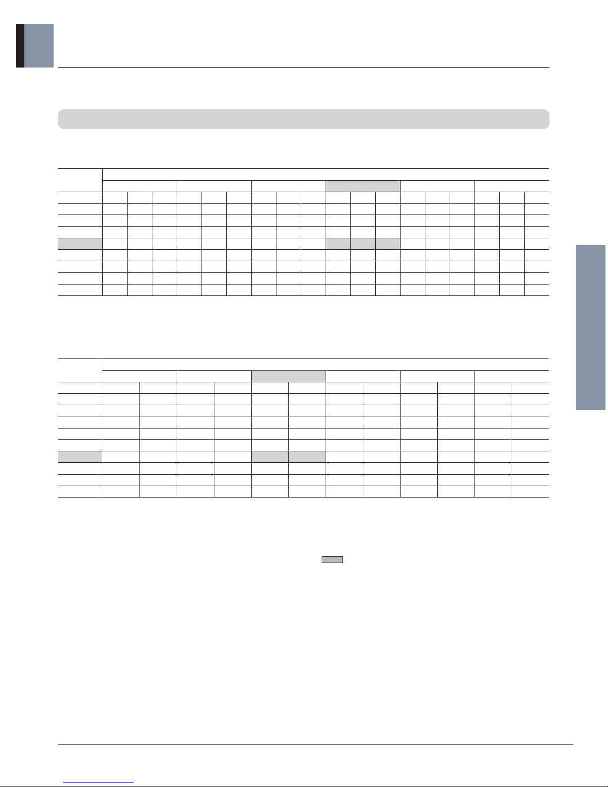
1.7 Capacity tables
Models :
AUUW24GD2 [LUU247HV] + ATNH24GPLE2 [LCN247HV]
• Cooling Capacity
• Heating Capacity
• Symbol
DB : Dry bulb temperature [°F]
WB : Wet bulb temperature [°F]
TC : Total capacity [kBtu/h]
SHC : Sensible capacity [kBtu/h]
PI : Power Input [kW]
(Comp.+ indoor fan motor+outdoor fan motor)
• Notes
1. All capacities are net. A deduction (cooling mode) or an
addition (heating mode) of Capacity due to operating
heat of indoor unit motor is reflected.
2. indicates rated capacity at the standard
temperature condition.
- Heating mode Outdoor conditions : 85%RH.
However, the condition on nominal capacity is
7°CDB/6°CWB(44.6°FDB/42.8°FWB)
3. Direct interpolation is permissible. Do not extrapolate.
4. Capacities are based on the following conditions:
- Interconnecting Piping Length : 7.6m(25ft)
- Level Difference : Zero.
SINGLE ZONE
Outdoor Air
Temperature
Indoor Air Temperature : °FDB / °FWB
68.0 / 57.2 71.6 / 60.8 77.0 / 64.4 80.6 / 66.2 86.0 / 71.6 89.6 / 75.2
°FDB TC SHC PI TC SHC PI TC SHC PI TC SHC PI TC SHC PI TC SHC PI
68.0 23.53 19.68 1.05 24.98 19.94 1.43 26.43 20.11 1.55 27.15 20.29 1.56 29.33 20.70 1.56 30.78 21.08 1.55
77.0 22.51 19.05 1.10 23.95 19.34 1.44 25.39 19.55 1.56 26.11 19.74 1.58 28.28 20.18 1.61 29.72 20.59 1.62
89.6 21.13 18.28 1.48 22.57 18.63 1.75 24.00 18.89 1.83 24.72 19.10 1.85 26.87 19.61 1.90 28.31 20.05 1.93
95.0 20.49 17.66 1.65 21.92 18.03 1.87 23.35 18.31 1.94 24.00 18.48 1.91 26.20 19.05 2.00 27.63 19.50 2.04
104.0 19.59 17.12 1.81 21.02 17.53 1.95 22.45 17.85 1.98 23.16 18.08 1.99 25.30 18.66 2.02 26.73 19.13 2.06
109.4 19.05 16.52 1.78 20.48 16.95 1.86 21.91 17.28 1.86 22.62 17.52 1.85 24.76 18.11 1.87 26.19 18.60 1.91
114.8 18.51 16.01 1.59 19.94 16.46 1.61 21.37 16.81 1.58 22.08 17.06 1.56 24.22 17.67 1.56 25.65 18.16 1.60
118.4 17.43 15.23 1.37 18.80 15.68 1.35 20.17 16.04 1.28 20.85 16.28 1.26 22.91 16.89 1.25 24.28 17.37 1.28
Outdoor Air
Temperature
Indoor Air Temperature : °FDB
60.8 64.4
68.0 69.8 71.6 75.2
°FWB
TC PI TC PI TC PI TC PI TC PI TC PI
-0.4 19.99 2.14 19.65 2.16 19.40 2.18 19.30 2.20 19.22 2.21 18.92 2.26
5.0 20.30 2.12 20.10 2.15 19.96 2.19 19.91 2.21 19.88 2.24 19.64 2.29
14.0 21.36 2.07 21.33 2.12 21.32 2.17 21.32 2.20 21.32 2.23 21.12 2.30
23.0 23.15 2.16 23.18 2.23 23.19 2.29 23.19 2.32 23.18 2.36 22.90 2.42
32.0 24.73 2.33 24.71 2.39 24.65 2.45 24.60 2.49 24.53 2.52 24.33 2.58
42.8 27.45 2.49 27.27 2.55 27.00 2.60 26.83 2.62 26.63 2.65 26.42 2.69
50.0 29.00 2.59 28.64 2.64 28.45 2.68 28.45 2.70 28.41 2.71 27.94 2.74
59.0 31.47 2.76 31.37 2.79 31.43 2.81 31.22 2.81 30.96 2.81 30.61 2.83
64.4 32.94 2.85 32.52 2.86 32.22 2.86 31.80 2.85 31.32 2.84 30.47 2.83

Outdoor Units
10 _ Heat pump 60Hz/R410A
1. DC Inverter SINGLE ZONE
SINGLE ZONE
Models : AUUW42GD2 [LUU427HV] + ATNH42GMLE2 [LCN427HV]
• Cooling Capacity
• Heating Capacity
• Symbol
DB : Dry bulb temperature [°F]
WB : Wet bulb temperature [°F]
TC : Total capacity [kBtu/h]
SHC : Sensible capacity [kBtu/h]
PI : Power Input [kW]
(Comp.+ indoor fan motor+outdoor fan motor)
• Notes
1. All capacities are net. A deduction (cooling mode) or an
addition (heating mode) of Capacity due to operating
heat of indoor unit motor is reflected.
2. indicates rated capacity at the standard
temperature condition.
- Heating mode Outdoor conditions : 85%RH.
However, the condition on nominal capacity is
7°CDB/6°CWB(44.6°FDB/42.8°FWB)
3. Direct interpolation is permissible. Do not extrapolate.
4. Capacities are based on the following conditions:
- Interconnecting Piping Length : 7.6m(25ft)
- Level Difference : Zero.
Outdoor Air
Temperature
Indoor Air Temperature : °FDB / °FWB
68.0 / 57.2 71.6 / 60.8 77.0 / 64.4 80.6 / 66.2 86.0 / 71.6 89.6 / 75.2
°FDB TC SHC PI TC SHC PI TC SHC PI TC SHC PI TC SHC PI TC SHC PI
68.0 41.18 34.00 2.25 43.72 34.45 3.05 46.25 34.74 3.30 47.52 35.05 3.33 51.32 35.75 3.33 53.86 36.41 3.31
77.0 39.39 32.90 2.35 41.91 33.41 3.07 44.44 33.77 3.31 45.70 34.10 3.36 49.48 34.86 3.42 52.01 35.57 3.45
89.6 36.98 31.57 3.15 39.50 32.18 3.72 42.01 32.62 3.90 43.26 32.99 3.95 47.03 33.87 4.04 49.54 34.63 4.12
95.0 35.86 30.51 3.52 38.36 31.14 3.99 40.85 31.62 4.14 42.00 31.92 4.07 45.85 32.91 4.27 48.35 33.68 4.35
104.0 34.29 29.58 3.86 36.78 30.28 4.16 39.28 30.83 4.22 40.53 31.23 4.23 44.28 32.22 4.30 46.78 33.04 4.39
109.4 33.34 28.54 3.79 35.84 29.27 3.96 38.34 29.85 3.96 39.59 30.27 3.95 43.34 31.29 3.99 45.83 32.12 4.07
114.8 32.40 27.65 3.40 34.90 28.42 3.44 37.40 29.04 3.36 38.65 29.46 3.33 42.39 30.52 3.33 44.89 31.37 3.41
118.4 30.50 26.31 2.93 32.90 27.08 2.87 35.30 27.70 2.74 36.50 28.12 2.69 40.09 29.17 2.66 42.49 30.01 2.73
Outdoor Air
Temperature
Indoor Air Temperature : °FDB
60.8 64.4
68.0 69.8 71.6 75.2
°FWB
TC PI TC PI TC PI TC PI TC PI TC PI
-0.4 34.80 3.34 34.21 3.36 33.77 3.40 33.60 3.42 33.46 3.45 32.93 3.51
5.0 35.34 3.30 34.98 3.35 34.75 3.41 34.66 3.45 34.60 3.48 34.19 3.57
14.0 37.18 3.22 37.12 3.30 37.11 3.39 37.11 3.43 37.12 3.48 36.76 3.58
23.0 40.30 3.37 40.35 3.47 40.37 3.57 40.37 3.62 40.35 3.67 39.86 3.77
32.0 43.04 3.62 43.02 3.72 42.91 3.82 42.82 3.87 42.70 3.92 42.36 4.02
42.8 47.77 3.88 47.46 3.97 47.00 4.05 46.70 4.09 46.36 4.12 45.99 4.19
50.0 50.49 4.03 49.86 4.11 49.52 4.17 49.52 4.20 49.46 4.22 48.63 4.26
59.0 54.78 4.30 54.62 4.34 54.71 4.37 54.35 4.38 53.90 4.38 53.29 4.41
64.4 57.34 4.44 56.62 4.46 56.09 4.45 55.36 4.44 54.52 4.42 53.04 4.40
 Loading...