

LG AT-C186PLE1, AT-C246PLE0, AT-C186PLE0, AT-C368NLE0, AT-C488MLE0 Installation Manual
...
INSTALLATION MANUAL
AIR
CONDITIONER
ENGLISH
Please read this installation manual completely before installing
*
the product.
Installation work must be performed in accordance with national wiring
*
standards by authorized personel only.
Please retain this installation manual for future reference after read it
*
throughly.
TYPE : CEILING CASSETTE AIR CONDITIONER
*MFL63260113*
Rev. : 01(05T15)
www.lg.com

Cassette Type Air Conditioner Installation Manual
TABLE OF CONTENTS
Installation
Requirements
Important Safety Instructions
Introduction
Symbols used in this Manual..........5
Features ...........................................5
Installation
Installation Tools...............................6
Selection of the best location.......7
Ceiling opening dimension and
hanging bolt location.......................10
The Indoor Unit Installation
Remote Controller Installation.....12
Remote ControlPreperation.........12
Wiring Connection.......................13
Electrical Wiring...........................14
Connection the cable to
Outdoor Unit................................14
Connection Pipes to the
Indoor Unit...................................15
Installation of Decorative Panel...17
Indoor Unit Drain Piping..............18
Test running................................20
Installation Instruction..................22
Installer Setting - Setting Address
of Central Contral.........................24
........................................5
........................................6
...... .3
..........11
Required Parts Required Tools
•
Connecting cable
•
Pipes: Gas side
Liquid side
•
Hanging Bolt
(W 3/8 or M10 length 650mm)
•
Insulated drain hose
•
Additional Drain hose
(Inner Diameter.............32mm)
•
Horizontal meter
•
Screw driver
•
Electric drill
•
Hole core drill (ø70mm)
•
Flaring Tools set
•
Torque Wrenches
•
Hexagonal Wrench (4mm, 5mm)
•
Gas-leak detector
•
Owner’s Manual
•
Installation Manual
•
Thermometer
•
Manifold gage
•
Vacuum pump
2 Ceiling Cassette Air Conditioner
Important Safety Instructions
Important Safety Instructions
Always comply with the following precautions to avoid dangerous situations and ensure peak
performance of your product
WARNING
!
It can result in serious injury or death when the directions are ignored
CAUTION
!
It can result in minor injury or product damage when the directions are ignored
WARNING
!
• Installation or repairs made by unqualied persons can result in hazards to you and others.
•
The product shall be installed according to the wiring regulations of the corresponding country.
• The information contained in the manual is intended for use by a qualied service technician
familiar with safety procedures and equipped with the proper tools and test instruments.
• Failure to carefully read and follow all instructions in this manual can result in equipment mal-
function, property damage, personal injury and/or death.
Installation
• Do not turn on the breaker or power under condition that front panel, cabinet, top cover, control box
cover are removed or opened.
- it may cause re, electric shock, explosion or death.
• Do not use a defective or underrated circuit breaker. Use this appliance on a dedicated circuit.
- There is risk of re or electric shock.
• For electrical work, contact the dealer, seller, a qualied electrician, or an Authorized Service Center.
- Do not disassemble or repair the product. There is risk of re or electric shock.
• Always ground the product.
- There is risk of re or electric shock.
• Install the panel and the cover of control box securely.
- There is risk of re or electric shock.
• Always install a dedicated circuit and breaker.
- Improper wiring or installation may cause re or electric shock
• Use the correctly rated breaker or fuse.
- There is risk of re or electric shock.
• Do not modify or extend the power cable.
- There is risk of re or electric shock.
• Be cautious when unpacking and installing the product.
- Sharp edges could cause injury. Be especially careful of the case edges and the ns on the con-
denser and evaporator.
• For installation, always contact the dealer or an Authorized Service Center.
- There is risk of re, electric shock, explosion, or injury.
• Do not install the product on a defective installation stand.
- It may cause injury, accident, or damage to the product.
• Be sure the installation area does not deteriorate with age.
- If the base collapses, the air conditioner could fall with it, causing property damage, product failure,
and personal injury.
Installation Manual 3
4 Ceiling Cassette Air Conditioner
Important Safety Instructions
• Do not let the air conditioner run for a long time when the humidity is very high and a door or a window
is left open.
- Moisture may condense and wet or damage furniture.
• Use a vacuum pump or Inert (nitrogen) gas when doing leakage test or air purge. Do not compress
air or Oxygen and Do not use Flammable gases. Otherwise, it may cause fire or explosion.
- There is the risk of death, injury, fire or explosion.
Operation
• Do not store or use flammable gas or combustibles near the product.
- There is risk of fire or failure of product.
CAUTION
!
Installation
• Always check for gas (refrigerant) leakage after installation or repair of product.
- Low refrigerant levels may cause failure of product.
• Install the drain hose to ensure that water is drained away properly.
- A bad connection may cause water leakage.
• Keep level even when installing the product.
- To avoid vibration or water leakage.
• Do not install the product where the noise or hot air from the outdoor unit could damage the neighborhoods.
- It may cause a problem for your neighbors.
• Use two or more people to lift and transport the product.
- Avoid personal injury.
• Do not install the product where it will be exposed to sea wind (salt spray) directly.
- It may cause corrosion on the product. Corrosion, particularly on the condenser and evaporator fins, could
cause product malfunction or inefficient operation.
NOTICE
Introduction
Symbols used in this Manual
This symbol alerts you to the risk of electric shock.
This symbol alerts you to hazards that may cause harm to the
air conditioner.
This symbol indicates special notes.
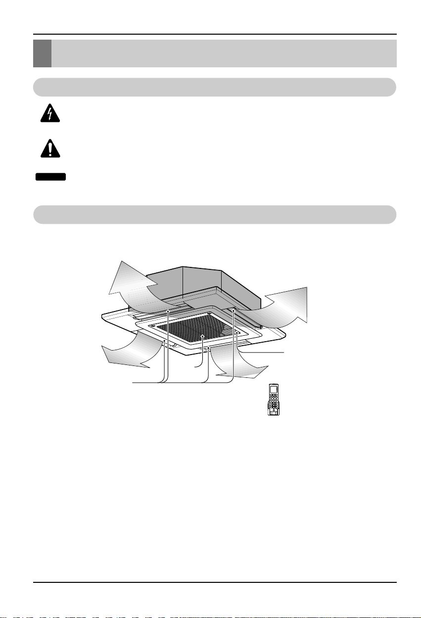
Features
Introduction
Air Outlet
Anti-bacteria filter
Air
Intake
Wireless Remote Controller
Installation Manual 5
Installation
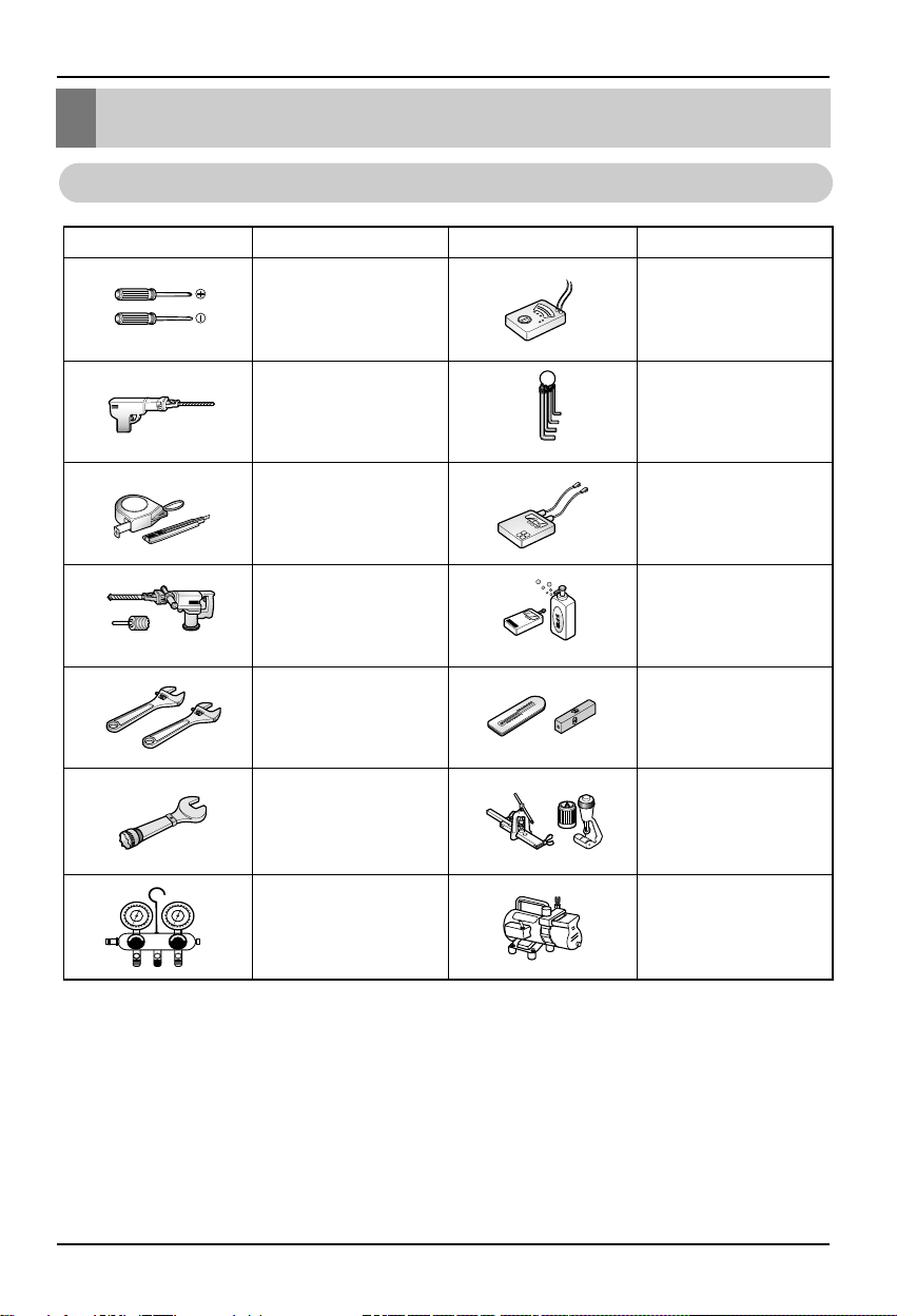
Installation
Installation Tools
Figure FigureName
Screw driver
Electric drill
Measuring tape, Knife
Hole core drill
Spanner
Torque wrench
Name
Ohmmeter
Hexagonal wrench
Ampmeter
Gas-leak detector
Thermometer,
Horizontal meter
Flaring tool set
Manifold gage Vacuum pump
6 Ceiling Cassette Air Conditioner

ecneF ro
selcatsbo
foornuS
ecneF ro
selcatsbo
foornuS
Installation
Selection
of the best location
1) Indoor unit
• There should not be any heat source or steam
near the unit.
• There should not be any obstacles to prevent
the air circulation.
• A place where air circulation in the room will
be good.
• A place where drainage can be easily
obtained.
• A place where noise prevention is taken into
consideration.
• Do not install the unit near the door way.
• Ensure the spaces indicated by arrows from
the wall, ceiling, or other obstacles.
• The indoor unit must keep the maintenance
space.
2) Outdoor unit
• If an awning is built over the unit to prevent
heat radiation from the condenser is not
• There should not be any animals or plants
• Ensure the spaces indicated by arrows from
10
Ceiling
Ceiling Board
50 or
more
or more
erom ro
001
360 or less
At least 180
Floor
direct sunlight or rain exposure, be careful that
restricted.
which could be affected by hot air discharged.
the wall, ceiling, fence or other obstacles.
Ceiling Board
50 or
more
ssel ro 03
Unit:cm
More than
30cm
More than
More than
30cm
30cm
More than 50cm
More than 70cm
More than
30cm
3) Settlement of outdoor unit
• Anchor the outdoor unit with a bolt and nut(ø10mm)
tightly and horizontally on a concrete or rigid mount.
• When installing on the wall, roof or rooftop, anchor the
mounting base securely with a nail or wire assuming the
influence of wind and earthquake.
• In the case when the vibration of the unit is conveyed to
the hose, secure the unit with an anti-vibration rubber.
More than
More than
30cm
30cm
More than 50cm
More than 70cm
Bolt
More than 50cm
(Service space)
Tubing connection
Installation Manual 7
Installation
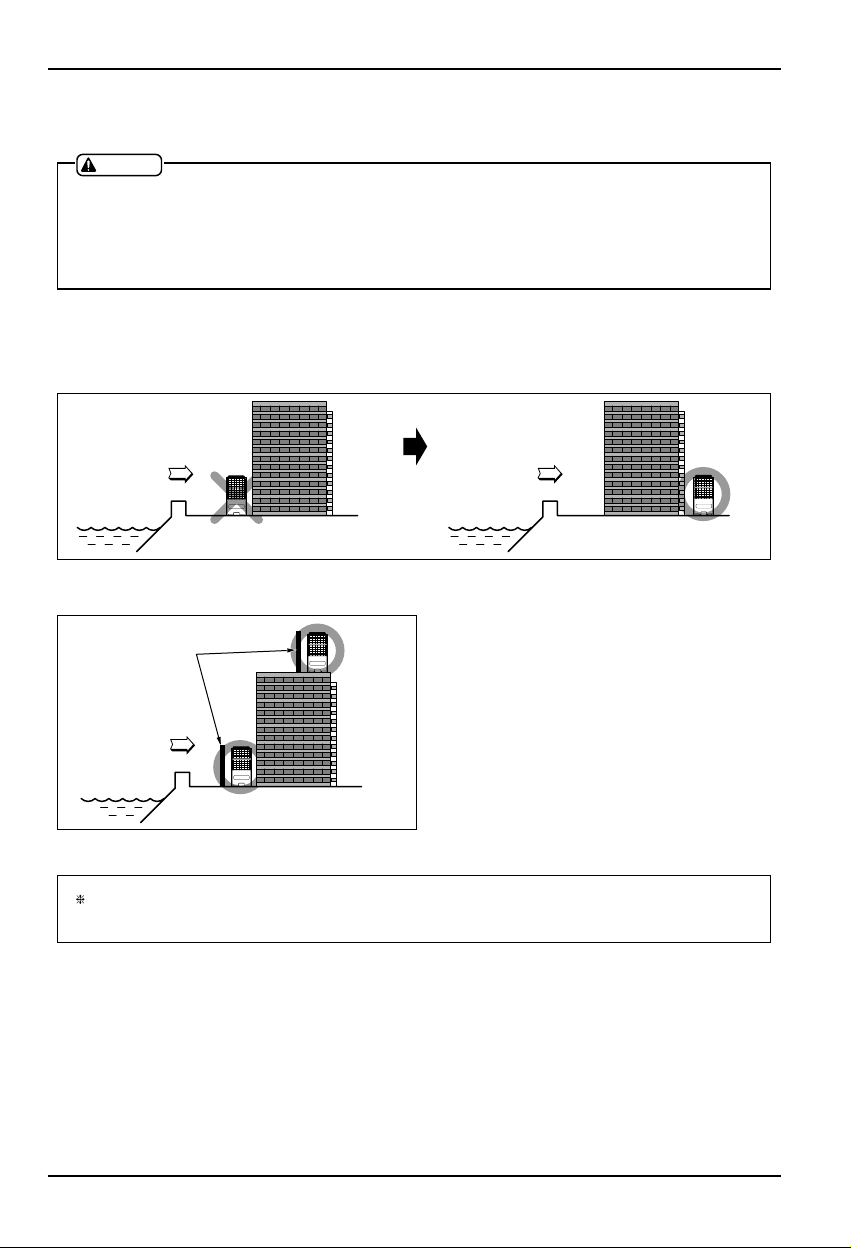
4) Installation guide at the seaside
CAUTION
1.
Air conditioners should not be installed in areas where corrosive gases, such as acid or alkaline gas, are produced.
2. Do not install the product where it could be exposed to sea wind (salty wind) directly. It can result corrosion
on the product. Corrosion, particularly on the condenser and evaporator fins, could cause product
malfunction or inefficient performance.
3. If outdoor unit is installed close to the seaside, it should avoid direct exposure to the sea wind. Otherwise it
needs additional anticorrosion treatment on the heat exchanger.
4.1 Selecting the location(Outdoor Unit)
1) If the outdoor unit is to be installed close to the seaside, direct exposure to the sea wind should be avoided.
Install the outdoor unit on the opposite side of the sea wind direction.
Sea wind Sea wind
2) In case, to install the outdoor unit on the seaside, set up a windbreak not to be exposed to the sea wind.
Windbreak
Sea wind
3) Select a well-drained place.
1.
If you can’t meet above guide line in the seaside installation, please contact LG Electronics for the additional anticorrosion treatment.
2. Periodic ( more than once/year ) cleaning of the dust or salt particles stuck on the heat exchanger by using water
• It should be strong enough like concrete to prevent
the sea wind from the sea.
• The height and width should be more than 150% of
the outdoor unit.
• It should be keep more than 70 cm of space
between outdoor unit and the windbreak for easy
air flow.
8 Ceiling Cassette Air Conditioner
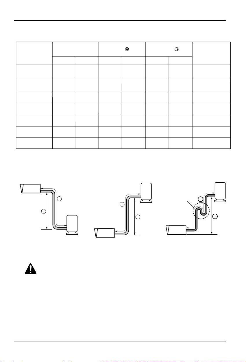
5) Piping length and the elevation
Installation
Model Name
AT-C186PLE0
AT-C186PLE1
AT-C246PLE0
AT-C308PLE0
AT-C368NLE0
AT-C488MLE0
AT-C548MLE0
Pipe Size
(Diameter:Ø )
Gas Liquid Standard Max. Standard Max.
1/2"
(12.70mm)
5/8"
(15.88mm)
5/8"
(15.88mm)
5/8"
(15.88mm)
5/8"
(15.88mm)
5/8"
(15.88mm)
3/4"
(19.05mm)
1/4"
(6.35mm)
3/8"
(9.52mm)
3/8"
(9.52mm)
3/8"
(9.52mm)
3/8"
(9.52mm)
3/8"
(9.52mm)
3/8"
(9.52mm)
Length (m) Elevation (m)
7.5 30 5
7.5 30 5 20 20
7.5 30 5
7.5 50 5
7.5 50 5
7.5 50 5
7.5 50 5
20
20
30
30
30
30
*Additional
refrigerant(g/m)
Extra refrigerant = (Extended length - Rated length) x Additional refrigerant.
Indoor unit
A
B
Outdoor unit
Indoor unit
A
Outdoor unit
B
4
Indoor unit
Oil trap
A
20
20
25
25
25
25
Outdoor unit
B
If piping length is more than 5m
CAUTION:
• Rated performance for refrigerant line length of:7.5m
• Capacity is based on standard length and maximum allowance length is on the
basis of reliability.
• Improper refrigerant charge may result in abnormal cycle.
• Oil trap should be installed every 10 meters.
Installation Manual 9
 Loading...