

LG AS-H096UM0, AS-H126UM0, AS-H126UM1, AS-H096UM3, AS-H126UM3 Service Manual

LG
Room
Air Conditioner
SERVICE MANUAL
LG
CAUTION
website http://www.lgservice.com
• BEFORE SERVICING THE UNIT, READ THE SAFETY
PRECAUTIONS IN THIS MANUAL.
• ONLY FOR AUTHORIZED SERVICE PERSONNEL.
MODELS: AS-H096U*M0
AS-H126U*M0
AS-H126U*M1
AS-H096U*M3
AS-H126U*M3

2 Room Air Conditioner
Air Conditioner Service Manual
TABLE OF CONTENTS
LG Model Name...............................................................................................................................................3
Safety Precautions..........................................................................................................................................4
Dimensions......................................................................................................................................................8
Symbols used in this Manual......................................................................................................................8
Indoor Unit.................................................................................................................................................8
Outdoor Unit...............................................................................................................................................9
Product Specifications ................................................................................................................................11
Installation.....................................................................................................................................................12
Select the best Location ..........................................................................................................................12
Piping Length and Elevation.....................................................................................................................13
Fixing Installation Plate ............................................................................................................................14
Drill a Hole in the Wall..............................................................................................................................14
Flaring Work.............................................................................................................................................15
Connecting the Piping..............................................................................................................................16
Connecting the Cables to the Indoor Unit ................................................................................................22
Connecting the Cables to the Outdoor Unit..............................................................................................23
Checking the Drainage.............................................................................................................................24
Forming the Piping...................................................................................................................................24
Air Purging ...............................................................................................................................................25
Air Purging with Vacuum Pump................................................................................................................25
Test Running............................................................................................................................................27
Operation ......................................................................................................................................................28
Function of Controls.................................................................................................................................28
Display Function ......................................................................................................................................35
Self-diagnosis Function............................................................................................................................35
Remote Control Operations......................................................................................................................36
Disassembly..................................................................................................................................................37
Indoor Unit................................................................................................................................................37
Schematic Diagram.......................................................................................................................................40
Electric Control Device.............................................................................................................................40
Wiring Diagram.........................................................................................................................................41
Components Location ..............................................................................................................................42
Troubleshooting Guide.................................................................................................................................44
Refrigeration Cycle Diagram....................................................................................................................44
2-way, 3-way Valve .................................................................................................................................45
Cycle Parts...............................................................................................................................................50
Electronic Parts........................................................................................................................................51
Exploded View...............................................................................................................................................58
Replacement Parts List ................................................................................................................................60
Service Manual 3
LG Model Name
LG Model Name
12 - 345678910
Code Type Code of Model Meaning
1 Producing Center, A~Z L: Chang-won R22 N: India
Refrigerant
A: Chang-won R410A
Z: Brazil
C: Chang-won R407C
D: Indonesia
T: China
U: China R410A
X: Mexico
K: Turkey R22
V: Vietnam
E: Turkey R410A
S: Out Sourcing
H: Thailand
2 Product Type A~Z S: Split Type Air Conditioner
3 Cooling/Heating/Inverter A~Z C: Cooling only
H: Heat pump
X: C/O + E/Heater
Z: H/P + E/Heater
V: AC Inverter C/O
N: AC Inverter H/P
Q: DC Inverter C/O
W: DC Inverter H/P
4, 5 Capacity 0~9 Cooling/Heating Capacity
Ex. "09" → 9,000 Btu/h
6 Electric Range 1~9 1: 115V/60Hz, A: 220V, 50Hz, 3Phase
A~Z 2: 220V/60Hz B: 208~230V, 60Hz, 3Phase
3: 208-230V/60Hz C: 575V, 50Hz, 3Phase
5: 200-220V/50Hz D: 440~460, 60Hz, 3Phase
6: 220-240V/50Hz E: 265V, 60Hz
7: 110V, 50/60Hz F: 200V, 50/60Hz
8: 380-415V/50Hz
9: 380-415V/60Hz
7 Chassis 1~9 Name of Chassis of Unit
Ex. 3 → S3 Chassis
8 Look A~Z Look,
Color (Artcool Model)
9 Function A~Z
10 Serial No. 1~9
Basic A
Basic+4Way B
Plasma Filter C
Plasma Filter+4 Way D
Tele+LCD E
Tele+LCD+Nano plasma+4Way F
Nano Plasma F+(A/changeover)+A/clean+Low A G
Nano Plasma F+(A/changeover)+A/clean+4way+Low A H
Tele+LED+4way I
Internet J
Plasma F+4Way+Oxy generator K
Nano Plasma F+(A/changeover)+A/clean L
Nano Plasma F+(A/changeover)+A/clean+4way M
Nano Plasma F+(A/changeover)+A/clean+PTC N
Nano Plasma F+(A/changeover)+Autoclean+4way+PTC P
Nano Plasma F+(A/changeover)+A/clean+4way+Low A+PTC Q
Negative ION+A/Clean R
(Nano)Plasma+Negative ION+A/Clean S
4way+(Nano)Plasma F+Negative ION+Healthy dehumidification+A/Clean
T
Nano Plasma F+4Way+(A/changeover)+A/clean+ U
LG Model Development Serial No.
* ARTCOOL COLOR
R Mirror
W White
B Blue
D Wood
M Metal
C Cherry
N Walnut
A Gogh
S Sisley
Q Quran
K Mecca
2004
4 Room Air Conditioner
Safety Precautions
Safety Precautions
To prevent injury to the user or other people and property damage, the following instructions must
be followed.
■ Incorrect operation due to ignoring instruction will cause harm or damage. The seriousness is
classified by the following indications.
■ Meanings of symbols used in this manual are as shown below.
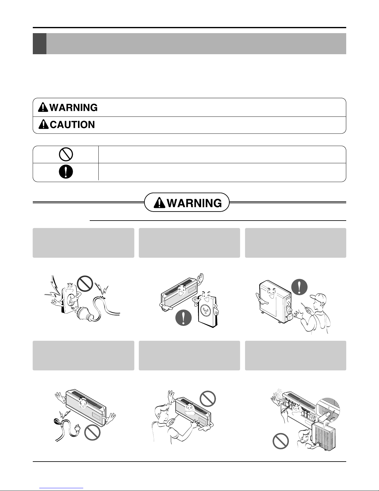
This symbol indicates the possibility of death or serious injury.
This symbol indicates the possibility of injury or damage to properties only.
Be sure not to do.
Be sure to follow the instruction.
Do not use damaged power
cords, plugs, or a loose socket.
• There is risk of fire or electric
shock.
Always use the power plug
and socket with the ground
terminal.
• There is risk of electric shock.
Install the panel and the cover
of control box securely.
• There is risk of fire or electric
shock.
■ Installation
Do not modify or extend the
power cord.
• There is risk of fire or electric
shock.
Do not install, remove, or reinstall the unit by yourself
(customer).
• There is risk of fire, electric shock,
explosion or injury.
Be cautious when unpacking
and installing the product.
• Shape edges could cause injury.
Be especially careful of the sharp
edges.
Service Manual 5
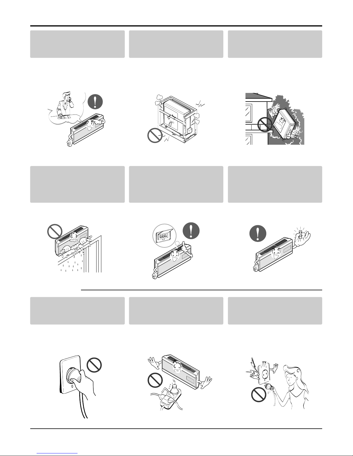
Safety Precautions
For installation, always contact the dealer or an
Authorized Service Center.
• There is risk of fire, electric shock,
explosion, or injury.
Do not install the product on a
defective installation stand.
• It may cause injury, accident, or
damage to the
product.
Be sure the installation area
does not deteriorate with age.
• If the base collapses, the air conditioner could fall with it, causing
property damage, product failure,
and personal injury.
Do not let the air conditioner
run for a long time when the
humidity is very high and a
door or a window is left open.
• Moisture may condense and wet or
damage furnishings.
Always install a dedicated
circuit and breaker.
• Improper wiring or installation may
cause fire or electric shock
Use the correctly rated breaker or fuse.
• There is risk of fire or electric
shock.
■ Operation
Do not turn the air-conditioner
ON or OFF by plugging or
unplugging the power plug.
• There is risk of fire or electric
shock.
Use a dedicated outlet for this
appliance.
• There is risk of fire or electric
shock.
Grasp the plug to remove the
cord from the outlet. Do not
touch it with wet hands.
• There is risk of fire or electric
shock.
6 Room Air Conditioner
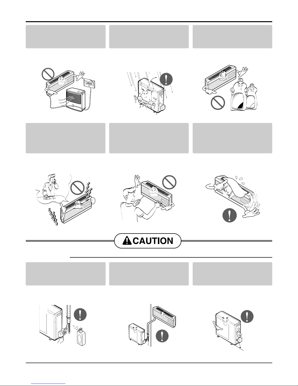
Safety Precautions
■ Installation
Unplug the unit if strange
sounds odors, or smoke
comes from it.
• There is risk of fire, failure of the
product, and/or electric shock.
Do not open the inlet grill of the
product during operation. (Do
not touch the electrostatic filter,
if the unit is so equipped.)
• There is risk of physical injury,
electric shock, or product.
Be cautious that water could
not enter the product.
• There is risk of fire, electrical shock
or product damage.
Do not place a heater or other
appliances near the power
cable.
• There is risk of fire, failure of the
product, and/or electric shock.
Do not allow water to run into
electric part.
• There is risk of fire, failure of the
product, and/or electric shock.
Do not store of use flammable
gas or combustibles near the
air conditioner.
• There is risk of fire or failure of
product.
Wax
Thinner
Always check for gas(refrigerant) leakage after installation
or repair of product.
• Low refrigerant levels may cause
failure of product.
Install the drain hose to
ensure that water is drained
away properly.
• A bad connection may cause water
leakage.
Keep level even when
installing the product.
• To avoid vibration or water leakage.
90˚
Service Manual 7
Safety Precautions
■ Operation
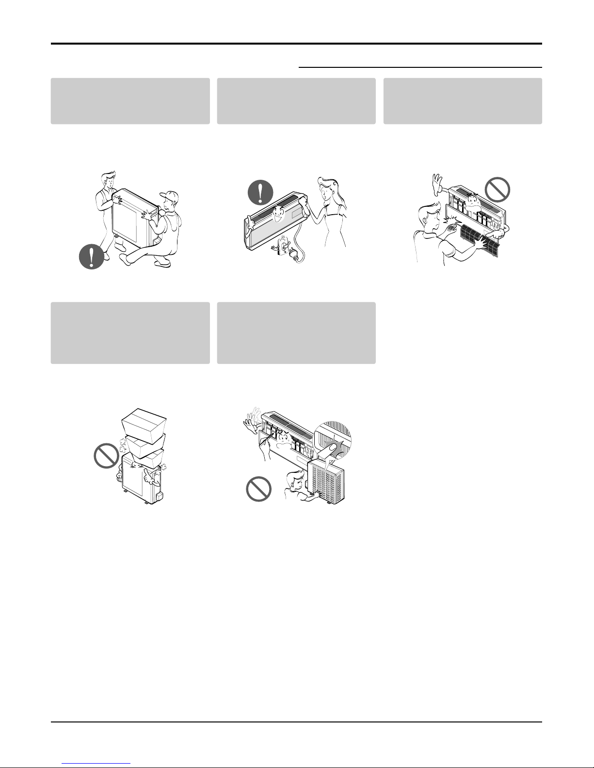
Use two or more people to lift
and transport the air conditioner
• Avoid personal injury.
Use a soft cloth to clean. Do
not use harsh detergents, solvents, etc.
• There is risk of fire, electric shock
or damage to the plastic parts of
the product.
Do not touch the metal parts of
the product when removing the
air filter. They are very sharp!
• There is risk of personal injury.
Do not step on or put anything
on the product. (outdoor unit)
• There is risk of personal injury and
failure of product.
Do not insert hands or other
objects through the air inlet or
outlet while the air conditioner
is plugged in.
• There are sharp and moving parts
that could cause personal injury.
8 Room Air Conditioner
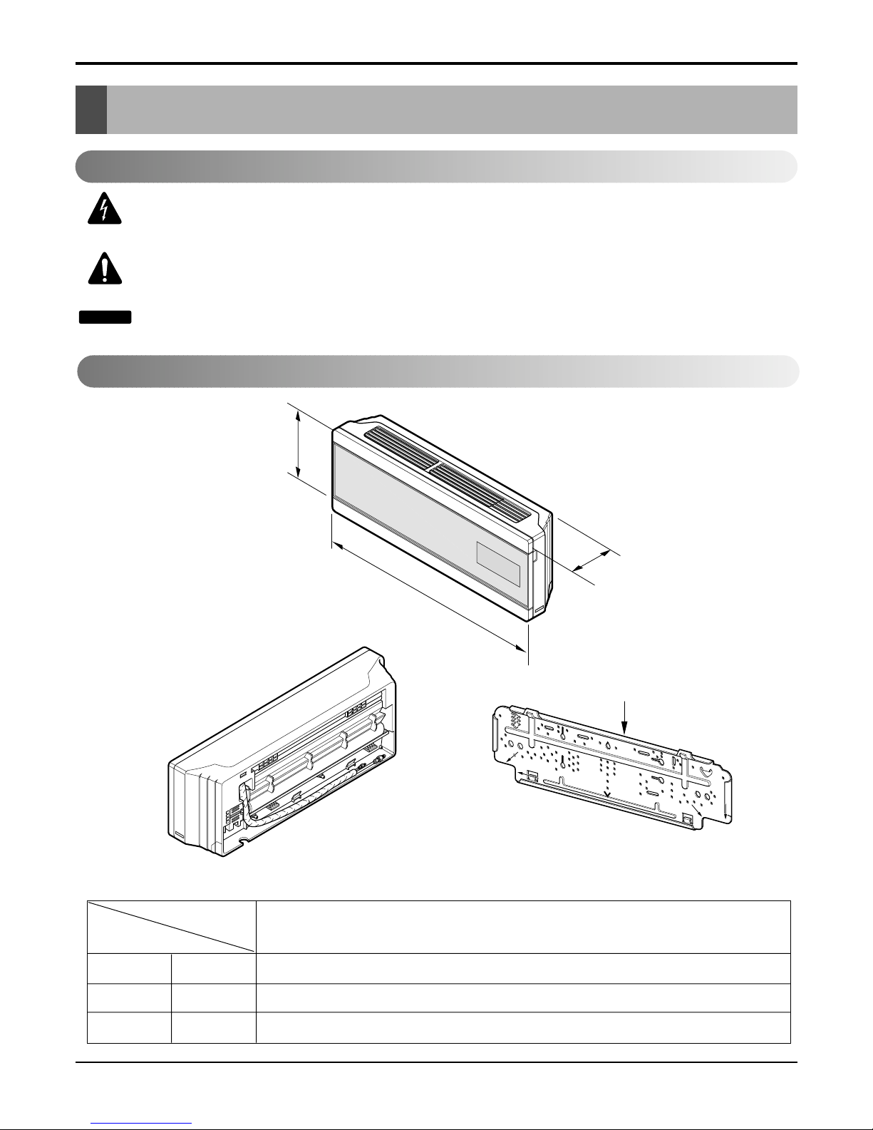
Dimensions
Dimensions
Installation plate
D
H
W
W mm 1030
H mm 290
D mm 153
Model
Dimension
INDOOR UNIT
Indoor Unit
This symbol alerts you to the risk of electric shock.
This symbol alerts you to hazards that may cause harm to the
air conditioner.
This symbol indicates special notes.
NOTICE
Symbols used in this Manual
Service Manual 9
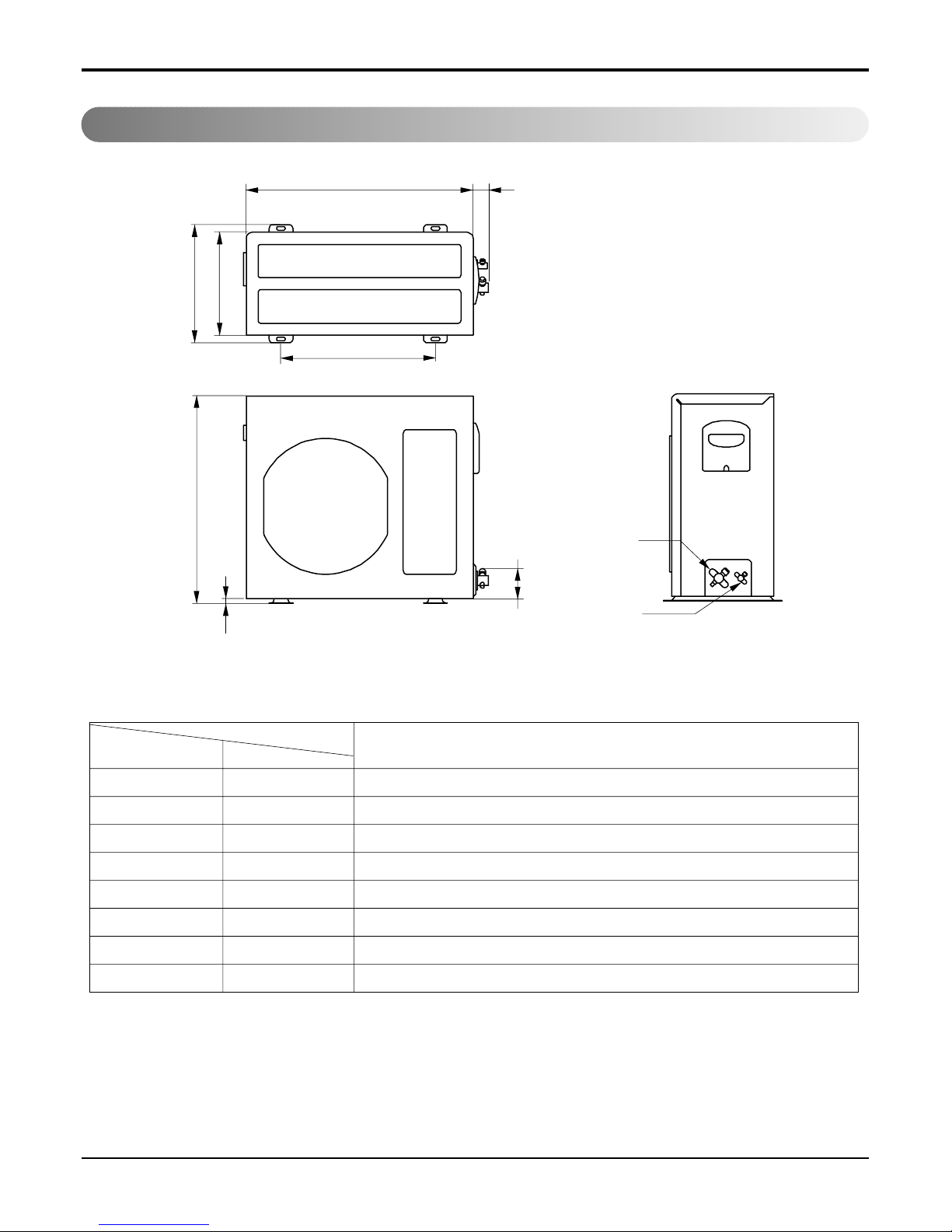
Outdoor Unit
Dimensions
W
L2
L3
L1
D
H
L4
L5
Gas side
(3-way valve)
Liquid side
(2-way valve)
MODEL
AS-H096U_Series
DIM unit
W mm 575
H mm 525
D mm 260
L1 mm 301
L2 mm 73
L3 mm 392
L4 mm 35
L5 mm 100

10 Room Air Conditioner
Dimensions
W
L2
L1
D
H
L4
L5
Gas side
(3-way valve)
Liquid side
(2-way valve)
MODEL
AS-H126U_Series
DIM unit
W mm 770
H mm 540
D mm 245
L1 mm 287
L2 mm 64
L3 mm 518
L4 mm 10
L5 mm 100
Service Manual 11
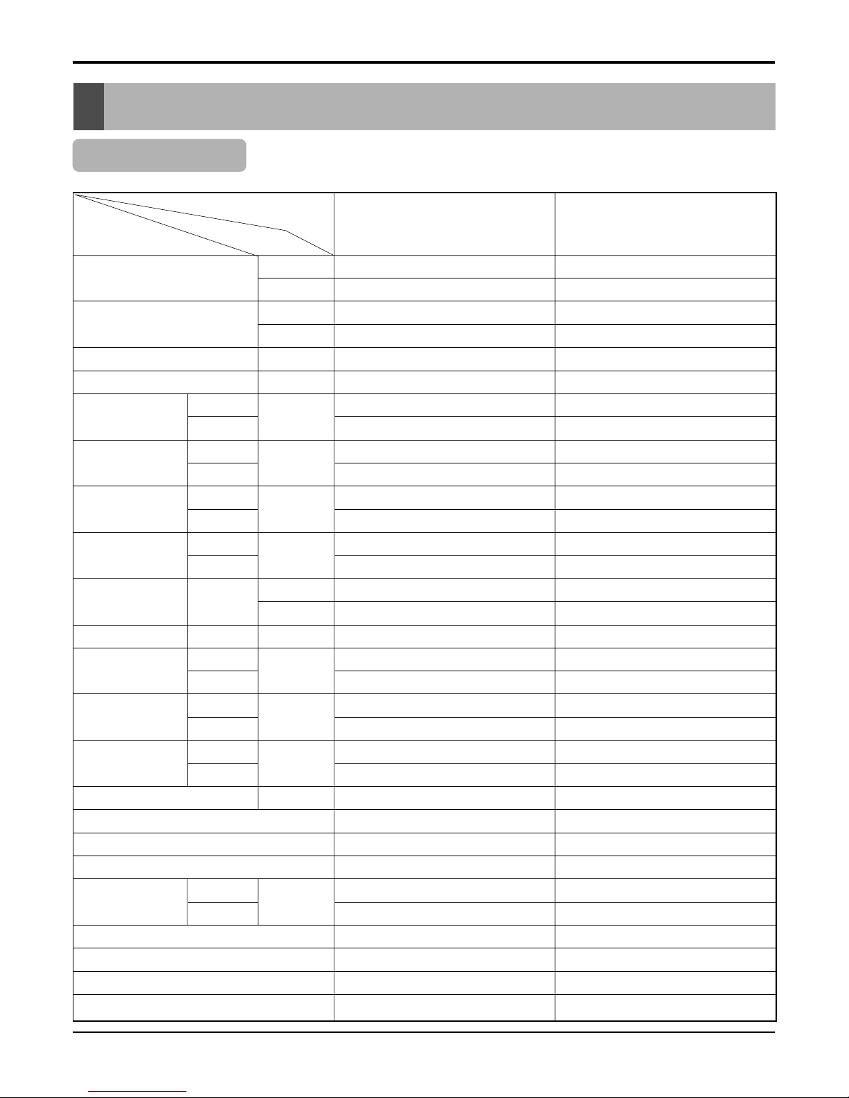
sProduct Specifications
Product Specifications
Table-1
Cooling Capacity
Btu/h
W
Heating Capacity
Btu/h
W
Moisture Removal l/h
Power Source Ø, V, Hz
Air Circulation
Indoor
m3/min
Outdoor
Noise Level
Indoor
dB (A)±3
Outdoor
Input
Cooling
W
Heating
Running Cooling
A
Current Heating
E.E.R. Cooling
Btu/hW
W/W
C.O.P Heating
Motor Output
Indoor
W
Outdoor
Dimensions
Indoor
mm
(W x H x D)
Outdoor
Net. Weight
Indoor
kg(lbs)
Outdoor
Refrigerant g
Airflow Direction Control (Up & Down)
Airflow Direction Control (Left & Right)
Remocon Type
Service Valve
Liquid
inch(mm)
Gas
Sleeping Operation
Drain Hose
Connecting Cable(p*mm2)
Power Cord(p*mm2)
9,550 12,000
2,800 3.52
9,900 12,700
2,900 3.72
1.2 1.5
1, 220-240, 50 1, 220-240, 50
8 9.5
20 26
32 36
46 48
910 1,130
850 1,150
4.0 5.0
3.7 5.2
10.5 10.63
3.08 3.12
3.41 3.23
9.5 12.9
27 25.5
1030 x 290 x 153 1030 x 290 x 153
575 x 252 x 260 770 x 540 x 245
9(19.8) 9(19.8)
25(50.1) 34(74.8)
760 880
OO
OO
L.C.D Wireless L.C.D Wireless
1/4(6.35) 1/4(6.35)
1/2(12.7) 1/2(12.7)
OO
OO
16:3*1.0 16:3*1.0
16:3*1.0 16:3*1.0
AS-H096U*M0
AS-H096U*M3
AS-H126U*M0
AS-H126U*M1
AS-H126U*M3
Model Name
Item Unit
12 Room Air Conditioner
Installation
Installation
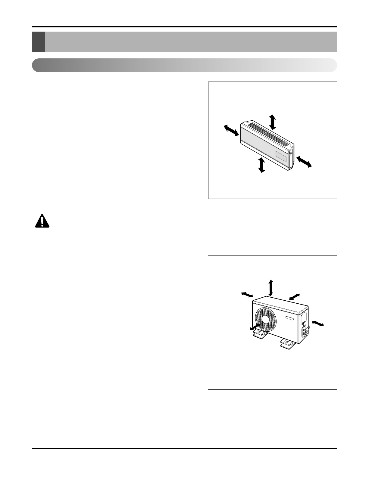
Indoor unit
1. Do not have any heat or steam near the unit.
2. Select a place where there are no obstacles in front
of the unit.
3. Make sure that condensation drainage can be conveniently routed away.
4. Do not install near a doorway.
5. Ensure that the interval between a wall and the left
(or right) of the unit is more than 50cm. The unit
should be installed as high as possible on the wall,
allowing a minimum of 10cm from ceiling.
6. Use a stud finder to locate studs to prevent unnecessary damage to the wall.
Outdoor unit
1. If an awning is built over the unit to prevent direct
sunlight or rain exposure, make sure that heat radiation from the condenser is not restricted.
2. Ensure that the space around the back and sides is
more than 10cm. The front of the unit should have
more than 70cm of space.
3. Do not place animals and plants in the path of the
warm air.
4. Take the weight of the air conditioner into account
and select a place where noise and vibration are minimum.
5. Select a place where the warm air and noise from the
air conditioner do not disturb neighbors.
Select the best Location
More than 10cm
More than
5cm
More than 2.3m
More than
5cm
CAUTION: Install the indoor unit on the wall where the height from the
floor is more than 2 meters.
More than 10cm More than 10cm
More
than 60cm
More than 60cm
More than 70cm
Service Manual 13
Installation
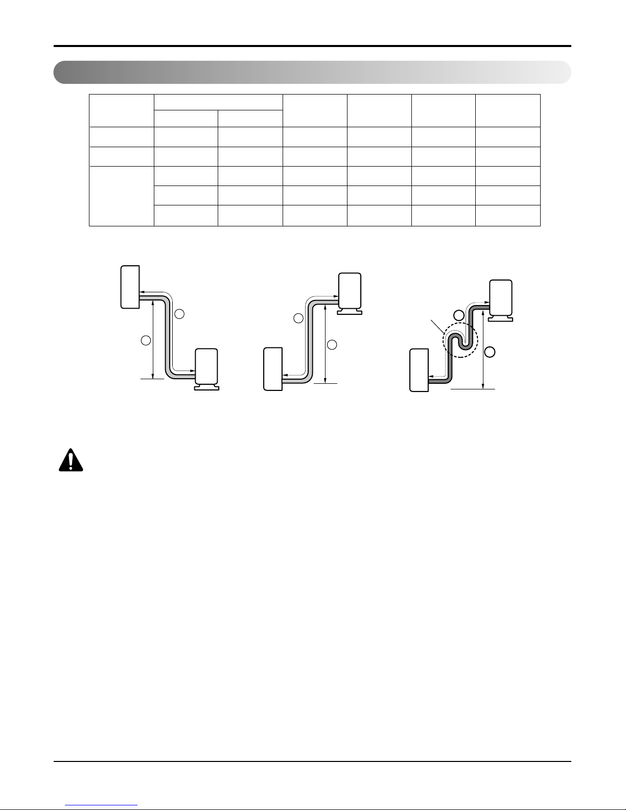
Piping Length and Elevation
7k, 8k, 9k 3/8" 1/4" 4 or 7.5 7 15 20
11k, 12k, 14k 1/2" 1/4" 4 or 7.5 7 15 20
1/2" 1/4" 4 or 7.5 15 30 20
18k, 24k, 26k 5/8" 1/4" 4 or 7.5 15 30 20
5/8" 3/8" 4 or 7.5 15 30 30
Pipe Size
Capacity
(Btu/h)
GAS LIQUID
Max.
Length A (m)
Additional
Refrigerant (g/m)
Max.
Elevation B (m)
Standard
Length (m)
Outdoor unit
Indoor unit
A
B
Outdoor unit
Indoor unit
A
B
A
Oil trap
Outdoor unit
Indoor unit
B
If piping length is more than 5m
CAUTION: Capacity is based on standard length and maximum allowance length is
on the basis of reliability.
Oil trap should be installed every 5~7 meters.
14 Room Air Conditioner
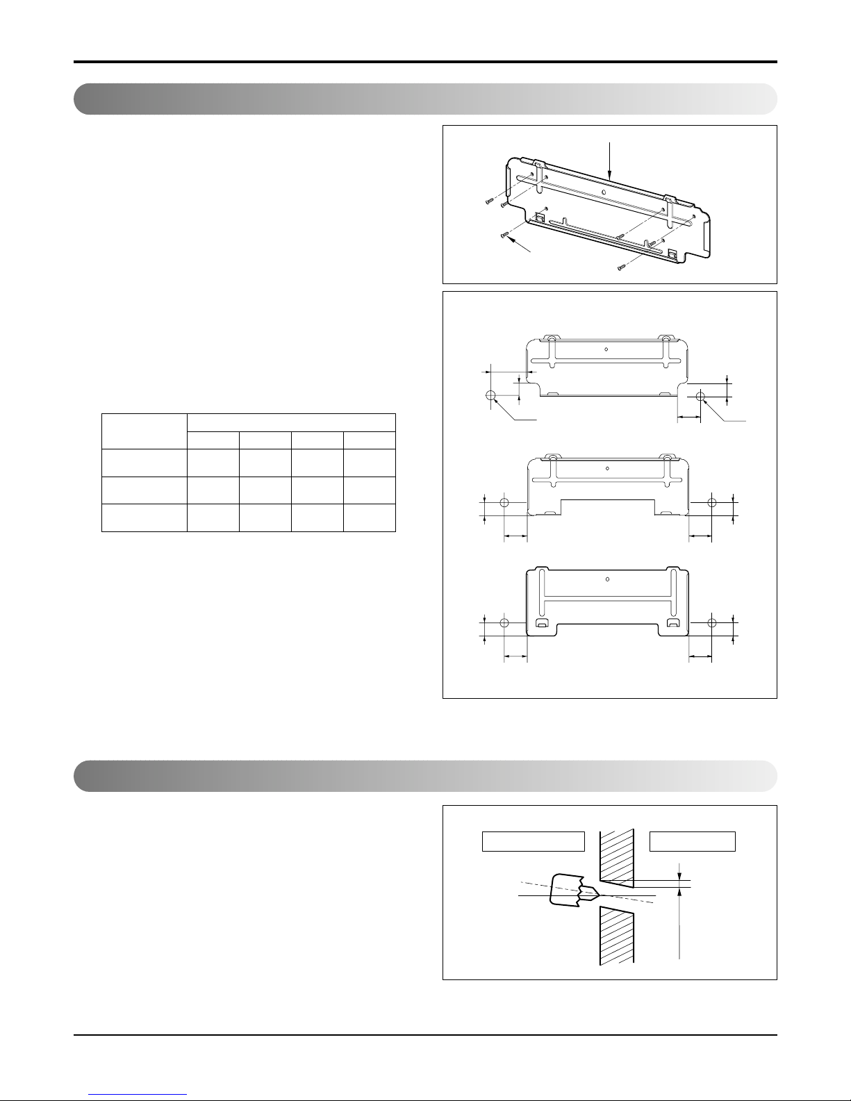
Installation
The wall you select should be strong and solid
enough to prevent vibration
1. Mount the installation plate on the wall with
type "A" screws. If mounting the unit on a concrete wall, use anchor bolts.
• Mount the installation plate horizontally by aligning
the centerline using a level.
2. Measure the wall and mark the centerline. It is
also important to use caution concerning the
location of the installation plate-routing of the
wiring to power outlets is through the walls typically. Drilling the hole through the wall for piping
connections must be done safely.
Fixing Installation Plate
Installation Plate
Type "A" screw
Installation plate
Ø70mm
Left rear piping Right rear piping
C
D
B
A
Ø70mm
Left rear piping Right rear piping
B
A
D
C
Right rear piping
B
A
D
C
Installation plate
(SU)
(SZ)
(S3)
Installation plate
• Drill the piping hole with a ø70mm hole core drill.
Drill the piping hole at either the right or the left
with the hole slightly slanted to the outdoor side.
Drill a Hole in the Wall
5-7mm
(3/16"~5/16")
Indoor
WALL
Outdoor
ABCD
SZ
35 33 156 33
(7k~9k)
SU
92 44 67 44
(11k~14k)
S3
58 3 292 3
(18k~26k)
CHASSIS
(Grade)
Distance (mm)
• For S3 chassis, the center of the unit is different
from that of the Installation plate.
Service Manual 15
Installation
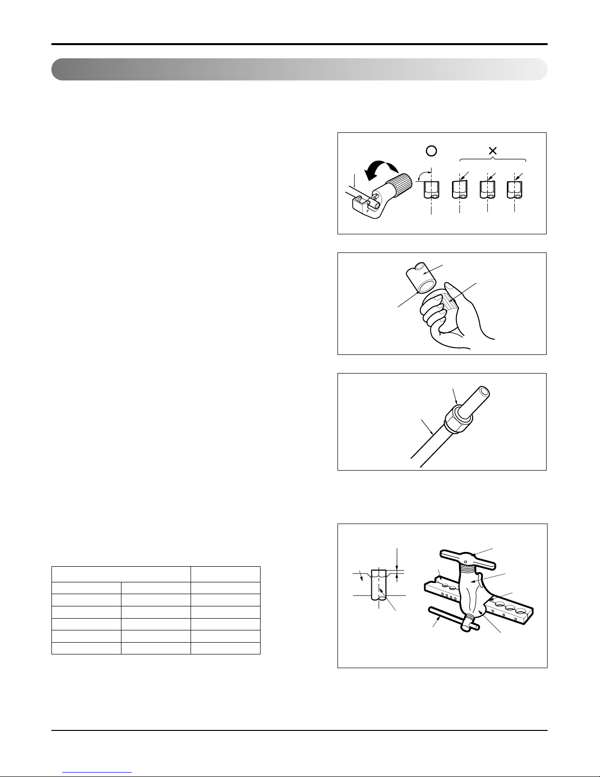
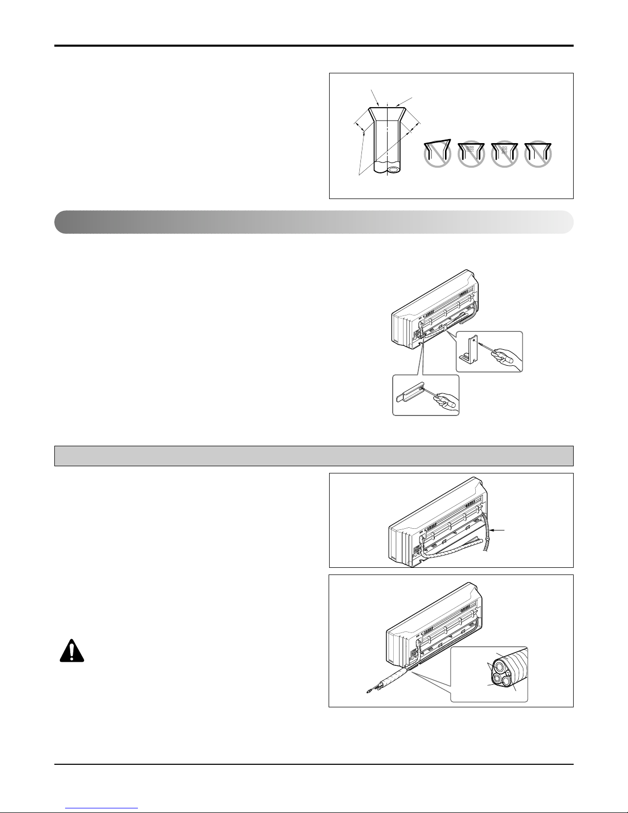
Flaring Work
Main cause for gas leakage is due to defect in flaring work. Carry out correct flaring work in the following procedure.
Cut the pipes and the cable.
1. Use the piping kit accessory or the pipes purchased
locally.
2. Measure the distance between the indoor and the
outdoor unit.
3. Cut the pipes a little longer than measured distance.
4. Cut the cable 1.5m longer than the pipe length.
Burrs removal
1. Completely remove all burrs from the cut cross section of pipe/tube.
2. Put the end of the copper tube/pipe in a downward
direction as you remove burrs in order to avoid dropping burrs into the tubing.
Putting nut on
• Remove flare nuts attached to indoor and outdoor unit,
then put them on pipe/tube having completed burr
removal.
(not possible to put them on after flaring work)
Flaring work
1. Firmly hold copper pipe in a die in the dimension
shown in the table below.
2. Carry out flaring work with the flaring tool.
Copper
pipe
90°
Slanted Uneven Rough
Pipe
Reamer
Point down
Flare nut
Copper tube
mm inch mm
Ø6.35 1/4 0~0.5
Ø9.52 3/8 0~0.5
Ø12.7 1/2 0~0.5
Ø15.88 5/8 0~1.0
Ø19.05 3/4 1.0~1.3
Outside diameter A
Bar
Copper pipe
Clamp handle
Red arrow mark
Cone
Yoke
Handle
Bar
"A"
16 Room Air Conditioner
Installation
Check
1. Compare the flared work with the figure by.
2. If a flared section is defective, cut it off and do flaring work again.
Indoor
1. Prepare the indoor unit's piping and drain hose for installation through the wall.
2. Remove the plastic tubing retainer(see the illustration by) and pull the tubing and drain hose away
from chassis.
3. Replace only the plastic tubing holder 1, not the
holder 2 in the original position.
1. Route the indoor tubing and the drain hose in the
direction of rear right.
2.
Insert the connecting cable into the indoor unit from
the outdoor unit through the piping hole.
• Do not connect the cable to the indoor unit.
• Make a small loop with the cable for easy connec-
tion later.
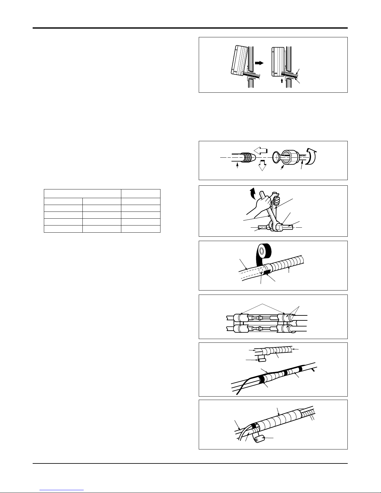
3. Tape the tubing, drain hose, and the connecting
cable. Be sure that the drain hose is located at the
lowest side of the bundle. Locating at the uper side
can cause drain pan to overflow inside the unit.
CAUTION: If the drain hose is routed inside
the room, insulate the hose with an insulation material* so that dripping from "sweating"(condensation) will not damage furniture
or floors.
*Foamed polyethylene or equivalent is recommended.
Inclined
Inside is shiny without scratches
Smooth all round
Even length
all round
Surface
damaged
Cracked Uneven
thickness
= Improper flaring =
Connecting the Piping
For right rear piping
Drain hose
Connecting
pipe
Connecting cable
Tape
Drain hose
Tubing holder 1
Tubing holder 2
Service Manual 17
Installation
4. Indoor unit installation
Hook the indoor unit onto the upper portion of the
installation plate.(Engage the two hooks of the rear
top of the indoor unit with the upper edge of the
installation plate.) Ensure that the hooks are properly seated on the installation plate by moving it left
and right.
Press the lower left and right sides of the unit
against the installation plate until the hooks engage
into their slots(clicking sound).
Connecting the piping to the indoor unit and drain
hose to drain pipe.
1. Align the center of the pipes and sufficiently tighten
the flare nut by hand.
2. Tighten the flare nut with a wrench.
3. When extending the drain hose at the indoor unit,
install the drain pipe.
Wrap the insulation material around the connecting portion.
1. Overlap the connection pipe insulation material and
the indoor unit pipe insulation material. Bind them
together with vinyl tape so that there may be no
gap.
2. Wrap the area which accommodates the rear piping
housing section with vinyl tape.
3. Bundle the piping and drain hose together by wrapping them with vinyl tape for enough to cover where
they fit into the rear piping housing section.
Drain hose
Connecting
cable
Indoor unit tubing Flare nut Pipes
Wrench
Indoor unit tubing
Open-end wrench (fixed)
Connection pipe
Flare nut
mm inch kg.m
Ø6.35 1/4 1.8
Ø9.52 3/8 4.2
Ø12.7 1/2 5.5
Ø15.88 5/8 6.6
Outside diameter Torque
Vinyl tape(narrow)
Adhesive
Drain pipe
Indoor unit drain hose
Plastic bands
Insulation material
Vinyl tape(narrow)
Connection pipe
Connecting cable
Vinyl tape (wide)
Wrap with vinyl tape
Indoor unit pipe
Pipe
Wrap with vinyl tape
Drain hose
Pipe
Vinyl tape(wide)
18 Room Air Conditioner
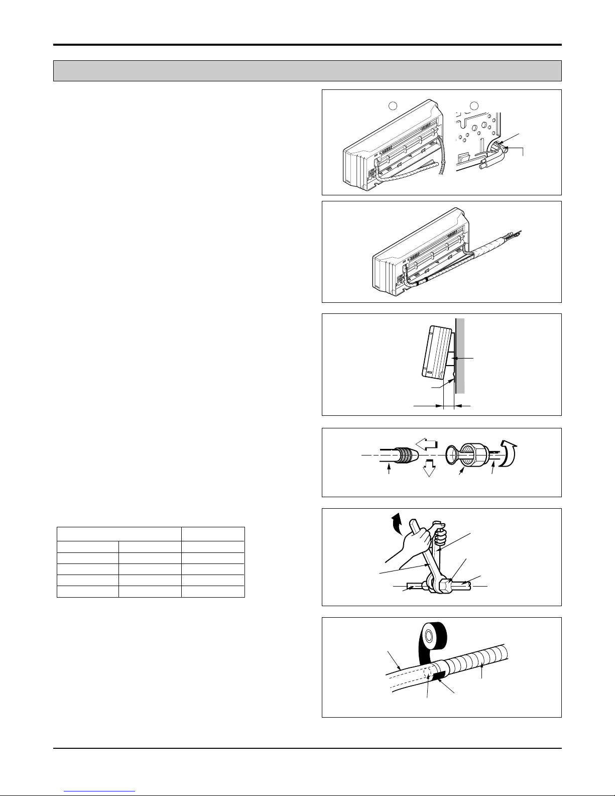
Installation
1. Route the indoor tubing and the drain hose to the
required piping hole position.
2. Insert the piping, drain hose, and the connecting
cable into the piping hole.
3.
Insert the connecting cable into the indoor unit.
• Don't connect the cable to the indoor unit.
• Make a small loop with the cable for easy connec-
tion later.
4. Tape the drain hose and the connecting cables.
5. Indoor unit installation
• Hang the indoor unit from the hooks at the top of
the installation plate.
• Insert the spacer etc. between the indoor unit and
the installation plate and separate the bottom of
the indoor unit from the wall.
Connecting the piping to the indoor unit and the
drain hose to drain pipe.
1. Align the center of the pipes and sufficiently tighten
the flare nut by hand.
2. Tighten the flare nut with a wrench.
3. When extending the drain hose at the indoor unit,
install the drain pipe.
For left rear piping
Drain pipe
Connecting
cable
1 2
Installation plate
Spacer
Indoor unit
8cm
Indoor unit tubing Flare nut Pipes
Wrench
Indoor unit tubing
Connection pipe
Flare nut
Open-end wrench (fixed)
Vinyl tape
Adhesive
Drain hose
Indoor unit drain hose
(narrow)
mm inch kg.m
Ø6.35 1/4 1.8
Ø9.52 3/8 4.2
Ø12.7 1/2 5.5
Ø15.88 5/8 6.6
Outside diameter Torque
Service Manual 19
Installation
Wrap the insulation material around the connecting portion.
1. Overlap the connection pipe heat insulation and the
indoor unit pipe heat insulation material. Bind them
together with vinyl tape so that there may be no
gap.
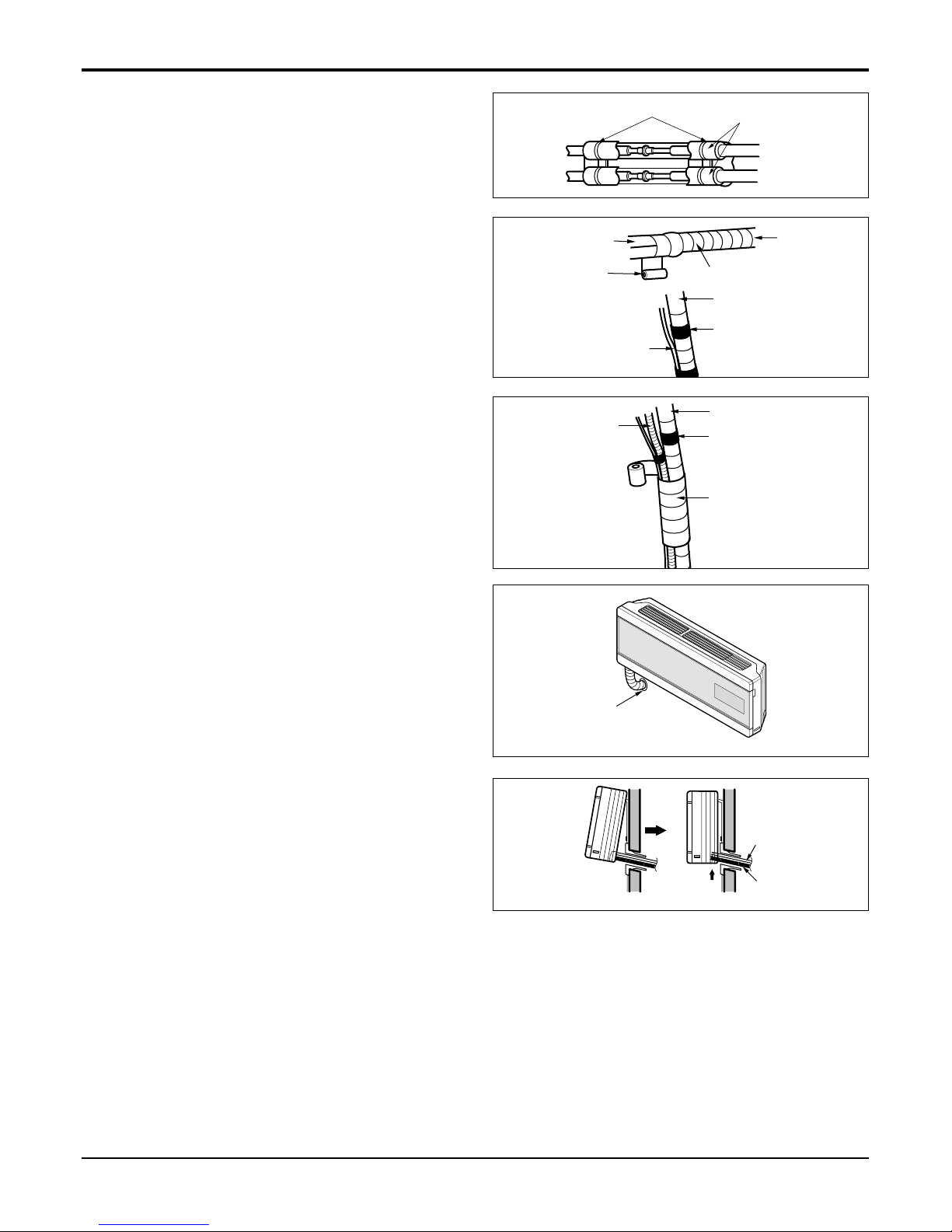
2. Wrap the area which accommodates the rear piping
housing section with vinyl tape.
3. Bundle the piping and drain hose together by wrapping them with cloth tape over the range within
which they fit into the rear piping housing section.
Reroute the pipings and the drain hose across the
back of the chassis.
Indoor unit installation
1. Remove the spacer.
2. Ensure that the hooks are properly seated on the
installation plate by moving it left and right.
3. Press the lower left and right sides of the unit
against the installation plate until the hooks engage
into their slots(clicking sound).
Plastic bands
Insulation material
Vinyl tape(narrow)
Connection
pipe
Connecting cable
Indoor
unit piping
Pipe
Vinyl tape
(wide)
Wrap with vinyl tape
Drain hose
Vinyl tape(narrow)
Pipe
Wrap with
vinyl tape(wide)
Piping for
passage through
piping hole
Drain hose
Connecting
cable
 Loading...