

LG AS-H096PDC0, AS-H126PMC0, AS-H126PDC0, AS-H096PMC0, LS-H096PBC0 Service Manual
...
SERVICE MANUAL
Room Air Conditioner
CAUTION
-BEFORE SERVICING THE UNIT, READ THE SAFETY
PRECAUTIONS IN THIS MANUAL.
-ONLY FOR AUTHORIZED SERVICE PERSONNEL.
MODEL : LS-H126P*C0
AS-H126P*C0
LS-C126P*C0
LS-H096P*C0
AS-H096P*C0
WEBSITE http://biz.LGservice.com

Contents
LG Model Name(2002)............................................................................................................ 3
LG Model Name(2003~).......................................................................................................... 4
Functions................................................................................................................................ 5
Product References .............................................................................................................. 7
Dimensions............................................................................................................................. 8
Refrigeration Cycle Diagram............................................................................................... 10
Wiring Diagram..................................................................................................................... 11
Operation Details ................................................................................................................. 13
Display Function .................................................................................................................. 19
Self-diagnosis Function....................................................................................................... 19
Installation ............................................................................................................................ 20
Operation .............................................................................................................................. 33
Disassembly of the parts (Indoor Unit).............................................................................. 34
2-way, 3-way Valve................................................................................................................ 36
Cycle Troubleshooting Guide.............................................................................................. 43
Electronic Parts Troubleshooting Guide............................................................................ 44
Electronic Control Device.................................................................................................... 51
Schematic Diagram.............................................................................................................. 53
Exploded View and Replacement Parts List...................................................................... 54
-2-
Code Type Code of Model Meaning
1 Producing Center/ A~Z
L: ChangWon R22, A: ChangWon R410A, C: ChangWon R407C
Refrigerant
3 Cooling & Heating A~Z C: Cooling Only Model
H: Heat Pump Model
4,5 Capacity(Btu/h) 1~9 Cooling/Heating Capacity
Ex. "12" ➔ 12,000Btu/h
6 Electric Range 1~9 Electric Standard
1 ➔ 115V/60Hz 6 ➔ 220~240V/50Hz
2 ➔ 220V/60Hz 7 ➔ 110V, 50/60Hz
3 ➔ 208~230V/60Hz 8 ➔ 380~415V/50Hz
5 ➔ 200~220V/50Hz 9 ➔ 380~415V/60Hz
7 Shassis A~Z Name of tool of unit
Ex: LS-P ’ SP Chassis
8 Look B, D, M B: Blue, D: Wood, M: Metal
9 Function A~Z
10 Serial No. 0~9
LG Model Name(2002)
-3-
12
-
Basic A
Basic + 4Way B
Plasma Filter C
Plasma Filter + 4Way D
Tele + LED + 4Way E
Tele + LCD + Plasma F + 4Way F
Tele Multi + LCD + Plasma F + 4Way G
Low A + Plasma F H
Low A + Plasma F + 4Way J
Plasma F + 4Way + Oxygen Generator K
A/change + Plasma F L
A/change + Plasma F + 4Way M
345678910
-4-
LG Model Name(2003~)
12
-
345678910
Code Type Code of Model Meaning
1 Producing Center, A~Z L: Chang-won R22 N: India
Refrigerant A: Chang-won R410A Z: Brazil
C: Chang-won R407C D: Indonesia
T: China M: Mexico
K: Turkey R22 V: Vietnam
E: Turkey R410A S: Out Sourcing
H: Thailand
2 Product Type A~Z S: Split Type Air Conditioner
3 Cooling/Heating/Inverter A~Z C: Cooling only
H: Heat pump
X: C/O + E/Heater
Z: H/P + E/Heater
V: AC Inverter C/O
N: AC Inverter H/P
Q: DC Inverter C/O
W: DC Inverter H/P
4, 5 Capacity 0~9 Cooling/Heating Capacity
Ex. "09" → 9,000 Btu/h
6 Electric Range 1~9 1: 115V/60Hz, A: 220V, 50Hz, 3Phase
A~Z 2: 220V/60Hz B: 208~230V, 60Hz, 3Phase
3: 208-230V/60Hz C: 575V, 50Hz, 3Phase
5: 200-220V/50Hz D: 440~460, 60Hz, 3Phase
6: 220-240V/50Hz E: 265V, 60Hz
7: 110V, 50/60Hz F: 200V, 50/60Hz
8: 380-415V/50Hz
9: 380-415V/60Hz
7 Chassis A~Z Name of Chassis of Unit
Ex. LSP → SP Chassis
8 Look A~Z Look,
Color (Artcool Model)
9 Function A~Z
10 Serial No. 1~9 LG Model De
* ARTCOOL COLOR
velopment Serial No.
Basic A
Basic+4Way B
Plasma Filter C
Plasma Filter+4 Way D
Tele+LCD E
Tele+LCD+Nano plasma+4Way F
Nano Plasma F+(A/changeove)+A/clean+Low A G
Nano Plasma F+(A/changeove)+A/clean+4way+Low A H
Tele+LED+4way I
Internet J
Plasma F+4Way+Oxy generator K
Nano Plasma F+(A/changeove)+A/clean L
Nano Plasma F+(A/changeove)+A/clean+4way M
Nano Plasma F+(A/changeove)+A/clean+PTC N
Nano Plasma F+(A/changeove)+Autoclean+4way+PTC P
Nano Plasma F+(A/changeove)+A/clean+4way+Low A+PTC Q
Negative ION+A/Clean R
(Nano)Plasma+Negative ION+A/Clean S
4way+(Nano)Plasma F+Negative ION+Healthy dehumidification+A/Clean
T
Nano Plasma F+4Way+(A/changeove)+A/clean+ U
R Mirror
W White
B Blue
D Wood
M Metal
C Cherry
Functions
• Room temperature sensor. (THERMISTOR)
• Maintains the room temperature in accordance with the Setting Temp.
• Indoor fan is delayed for 5 sec at the starting.
• Restarting is inhibited for approx. 3 minutes.
• High, Med, Low, CHAOS
• Intermittent operation of fan at low speed.
• The fan is switched to low(Cooling), med(Heating) speed.
• The unit will be stopped after 1, 2, 3, 4, 5, 6, 7 hours.
• The fan is switched to intermittent or irregular operation
•
The fan speed is automatically switched from high to low speed.
• The louver can be set at the desired position or swing
up and down automatically.
Indoor Unit
Operation ON/OFF by Remote controller
Sensing the Room Temperature
Room temperature control
Starting Current Control
Time Delay Safety Control
Indoor Fan Speed Control
Operation indication Lamps (LED)
Soft Dry Operation Mode
• Both the indoor and outdoor fan stops during defrosting.
• The indoor fan stops until the
evaporator pipe temperature will be reached
at 28°C.
Sleep Mode Auto Control
Natural Air Control by CHAOS Logic
Airflow Direction Control
-5-
Defrost(Deice) control (Heating)
Hot-start Control (Heating)
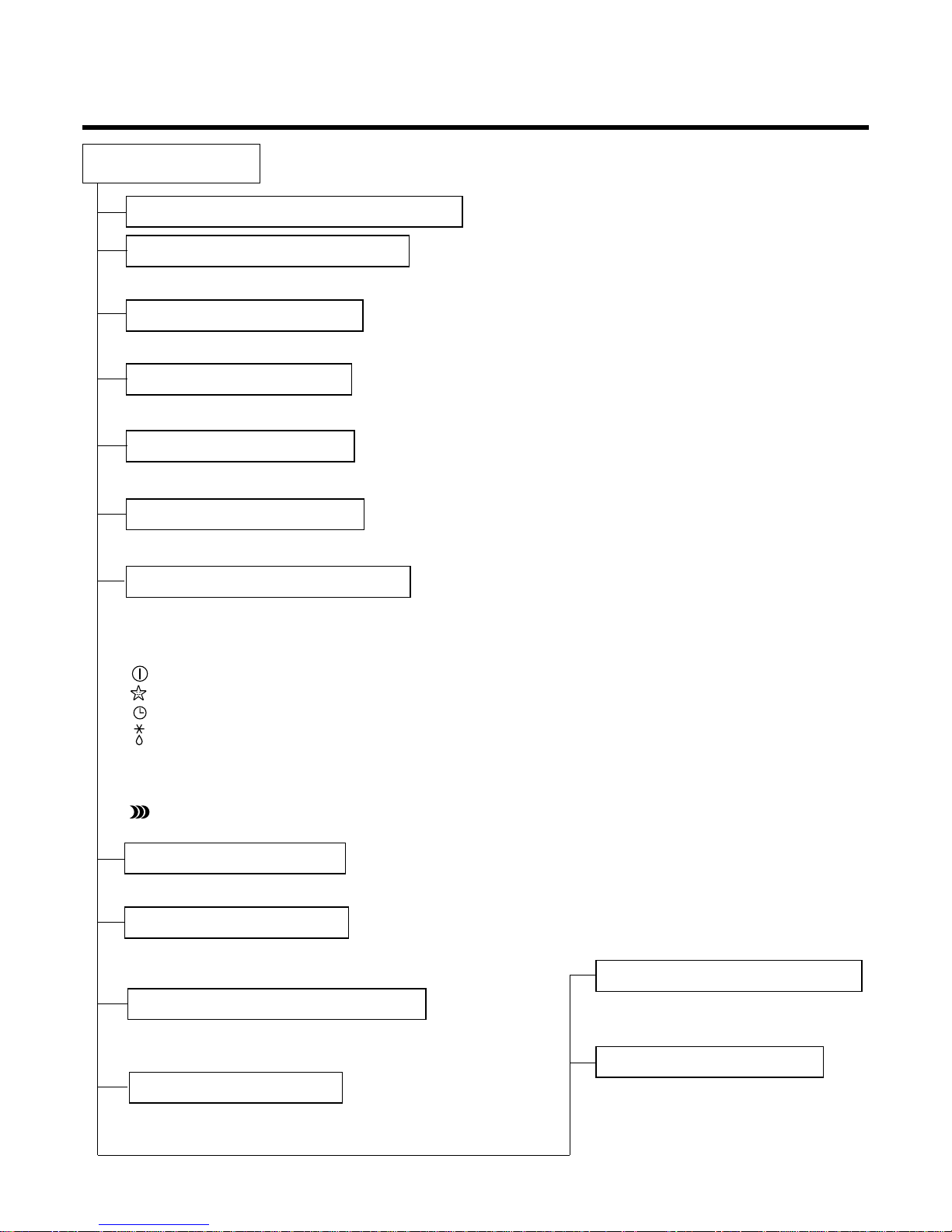
Signal Receptor
Receives the signals from the remote control.(Signal receiving sound: two short beeps or one long beep.)
Operation Indication Lamps
On/Off : Lights up during the system operation.
Sleep Mode : Lights up during Sleep Mode Auto operation.
Timer : Lights up during Timer operation.
Defrost Mode : Lights up during Defrost Mode or
Hot Start operation.(Heat pump model only)
Outdoor unit operation : Lights up during outdoor unit operation.
(Cooling model only)
PLASAM : Indicate operation of PLASMA purifier.
OUT
DOOR
-6-
Healthy Dehumidification Operation Mode.
( )
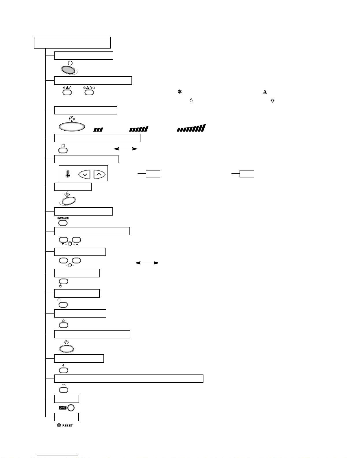
Remote Control
Operation ON/OFF
Reset
Operation Mode Selection
Temperature Setting
Timer Selection
Timer Setting
JET COOL
Timer Cancel
Sleep Operation
Airflow Direction Control
(Cooling
model only)
(Heating
model only)
TEMPERATURE
LOW HIGH
Cooling Operation Mode.( )
Heating Operation Mode.( )
Auto Operation Mode.( )
Air Circulation
Horizontal Airflow Direction Control Button(Optional)
Room, Temperature Checking
Setting the Time or Timer
PLASMA(Optional)
Fan Speed Selection
(Low) (Med) (High)
ON
OFF
CANCEL
SET
2nd F
: (Low:11°C High:39°C)
: OFF, ON, OFF ON
: Cancel Sleep Mode, Timer ON or Timer OFF
: 1, 2, 3, 4, 5, 6, 7, Off Timer
: Fan Operates without cooling or heating.
Cooling
Down to 18°C
Up to 30°C
Heating
Down to 16°C
Up to 30°C
-7-
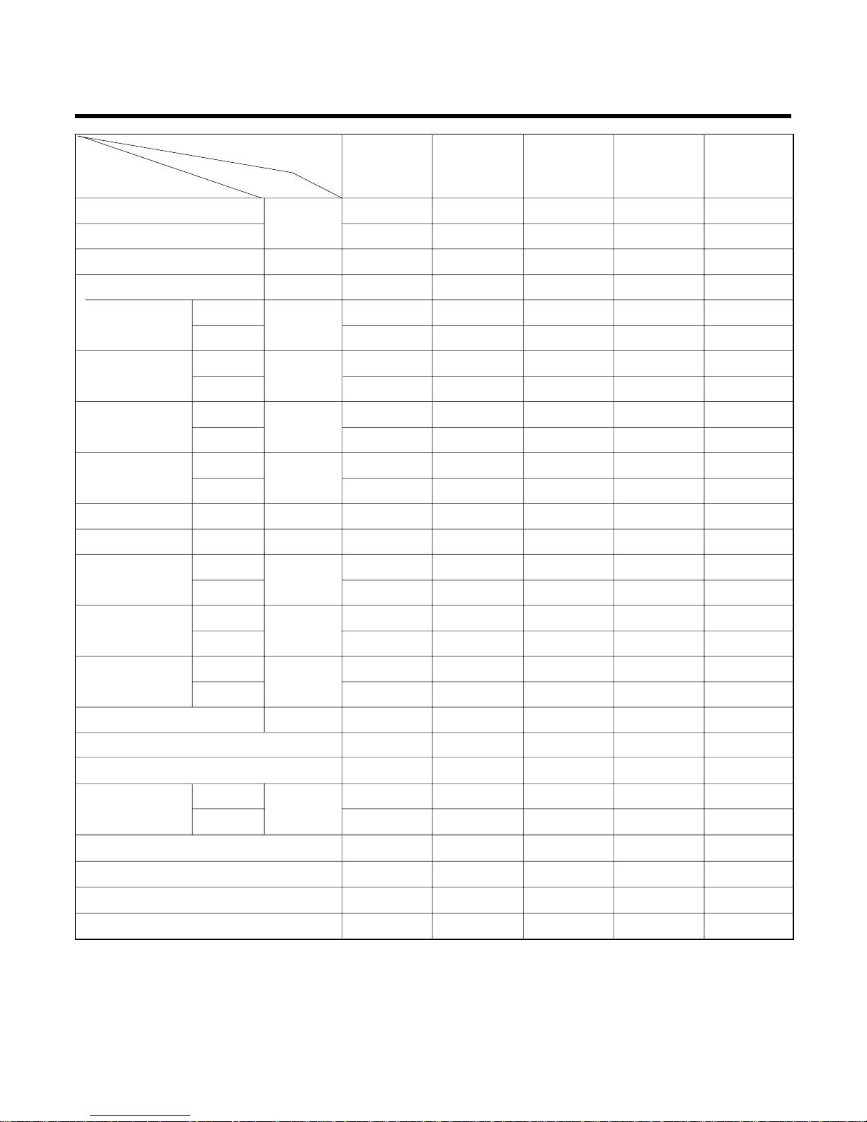
Product References
Model Name
Item Unit
Cooling Capacity
Btu/h
Heating Capacity
Moisture Removal l/h
Power Source Ø, V, Hz
Cooling
W
Heating
Running Cooling
A
Current Heating
E.E.R. Cooling Btu/hW
C.O.P Heating
Refrigerant g
Airflow Direction Control (Up & Down)
Remocon Type
inch(mm)
Sleeping Operation
Drain Hose
Connecting Cable
Power Cord
11,000 11,500 11,000 9,000 9,200
12,500 11,500 9,300 9,400
1.2 1.5 1.23 1.2 1.2
1,220~240,50 1,220~240,60 1,220~240,50 1,220~240,50 1,220~240,50
8.3 8.3 8.36 7.5 7.5
26 26 26 26 26
42 42 42 37 37
48 48 46 47 47
1,220 1,220 1,250 940 840
1250 1220 910 860
5.8 5.5 5.8 4.1 3.8
5.5 5.5 4 3.85
9.2 9.43 8.8 9.57 10.95
2.9 2.8 3 3.2
24 24 24 24 24
25.5 27 25.5 27 27
570*568*137 570*568*137 570*568*137 570*568*137 570*568*137
770*540*245 770*540*245 770*540*245 770*540*245 770*540*245
99999
34 34 34 34 34
800(R-22) 990(R-410) 980(R-22) 950(R-22) 870(R-410)
OOOOO
LCD Wireless LCD Wireless LCD Wireless LCD Wireless LCD Wireless
1/4(6.35) 1/4(6.35) 1/4(6.35) 1/4(6.35) 1/4(6.35)
1/2(12.7) 3/8(9.52) 1/2(12.7) 3/8(9.52) 3/8(9.52)
OOOOO
OOOOO
1.0MM 1.0MM 1.0MM 1.0MM 1.0MM
1.0MM 1.0MM 1.0MM 1.0MM 1.0MM
Air Circulation
Noise Level
Input
m3/min
dB (A)±3
Indoor
Outdoor
Indoor
Outdoor
Indoor
Outdoor
Indoor
Outdoor
Indoor
Outdoor
Liquid
Gas
Service Valve
Motor Output
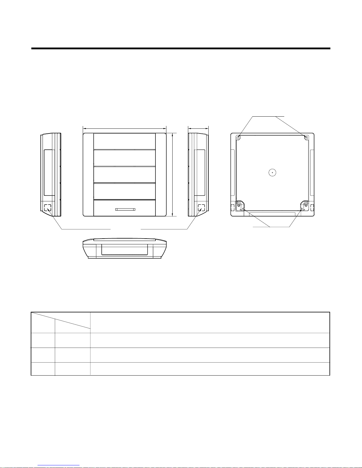
Dimensions
(W x H x D)
Net. Weight
W
mm
kg
NOTE: Please refer to Label Quality on the product since this specification may be changed for improving
performance
LS-H126P_ AS-H126P_ LS-C126P_ LS-H096P_ AS-H096P_
-8-
Pipe Hole
Fix Hole
Hanger Hole
H
W
D
MODEL
DIM Unit
W mm 570
H mm 568
D mm 137
INDOOR UNIT
Dimensions
(1) Indoor Unit
-9-
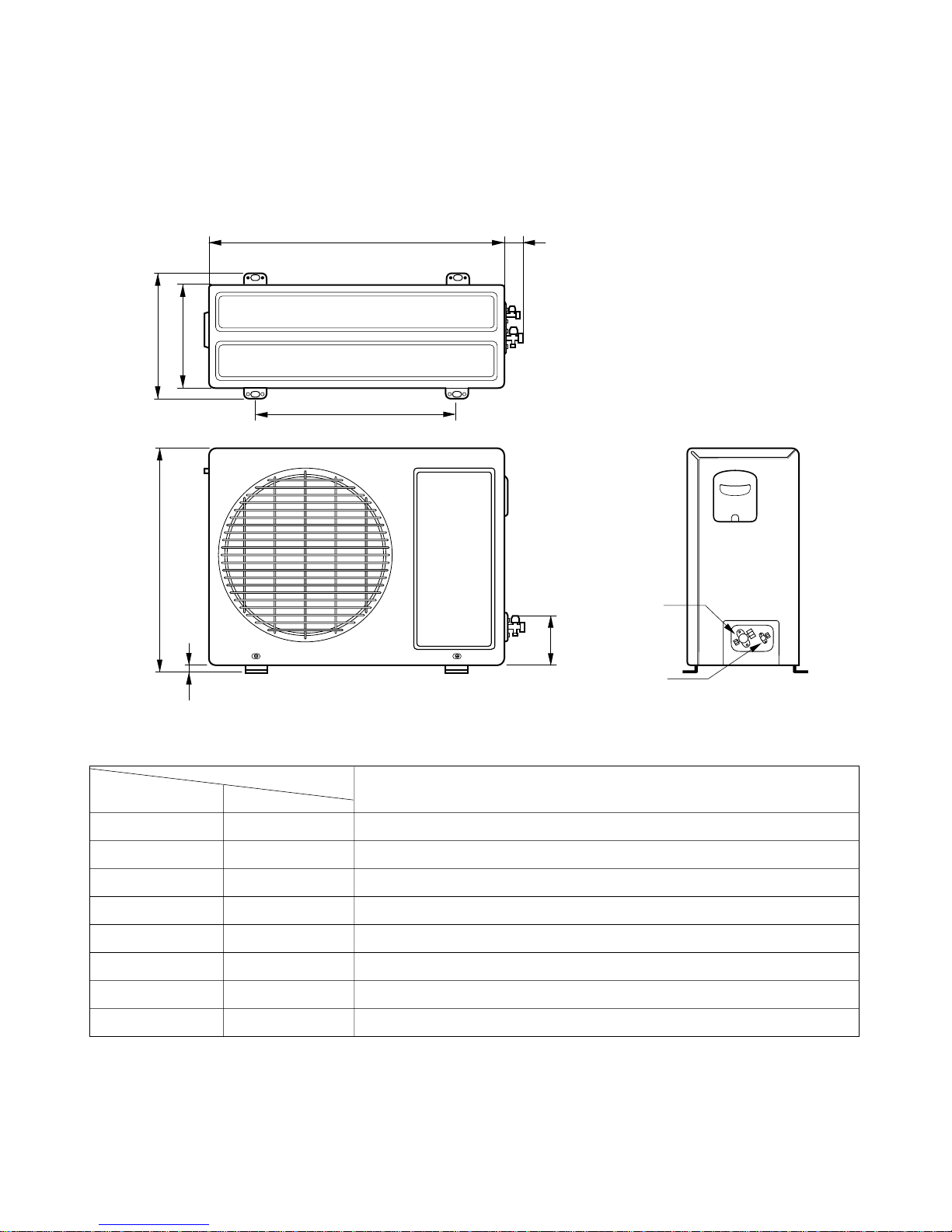
(2) Outdoor Unit
W
L2
L3
L1
D
H
L4
L5
Gas side
(3-way valve)
Liquid side
(2-way valve)
MODEL
All Models
DIM unit
W mm 770
H mm 540
D mm 245
L1 mm 287
L2 mm 64
L3 mm 518
L4 mm 10
L5 mm 100
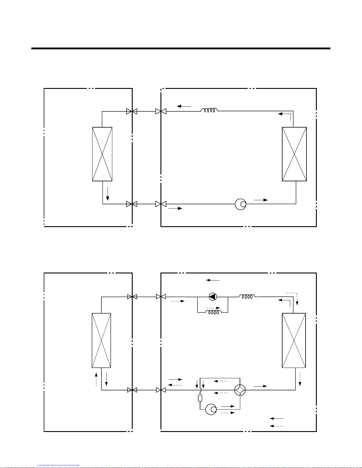
Refrigeration Cycle Diagram
-10-
INDOOR UNIT OUTDOOR UNIT
INDOOR UNIT OUTDOOR UNIT
HEAT
EXCHANGE
(EVAPORATOR)
HEAT
EXCHANGE
(EVAPORATOR)
HEAT
EXCHANGE
(CONDENSER)
HEAT
EXCHANGE
(CONDENSER)
COMPRESSOR
COMPRESSOR
ACCUMU
LATOR
GAS SIDE
GAS SIDE
VALVE
LIQUID SIDE
LIQUID SIDE
VALVE
CAPILLARY TUBE
CAPILLARY TUBE
CHECK VALVE
(Heating Model only)
COOLING
HEATING
REVERSING
VALVE
(Heating Model Only)
(1) Cooling Only Models
(2) Cooling & Heating Models
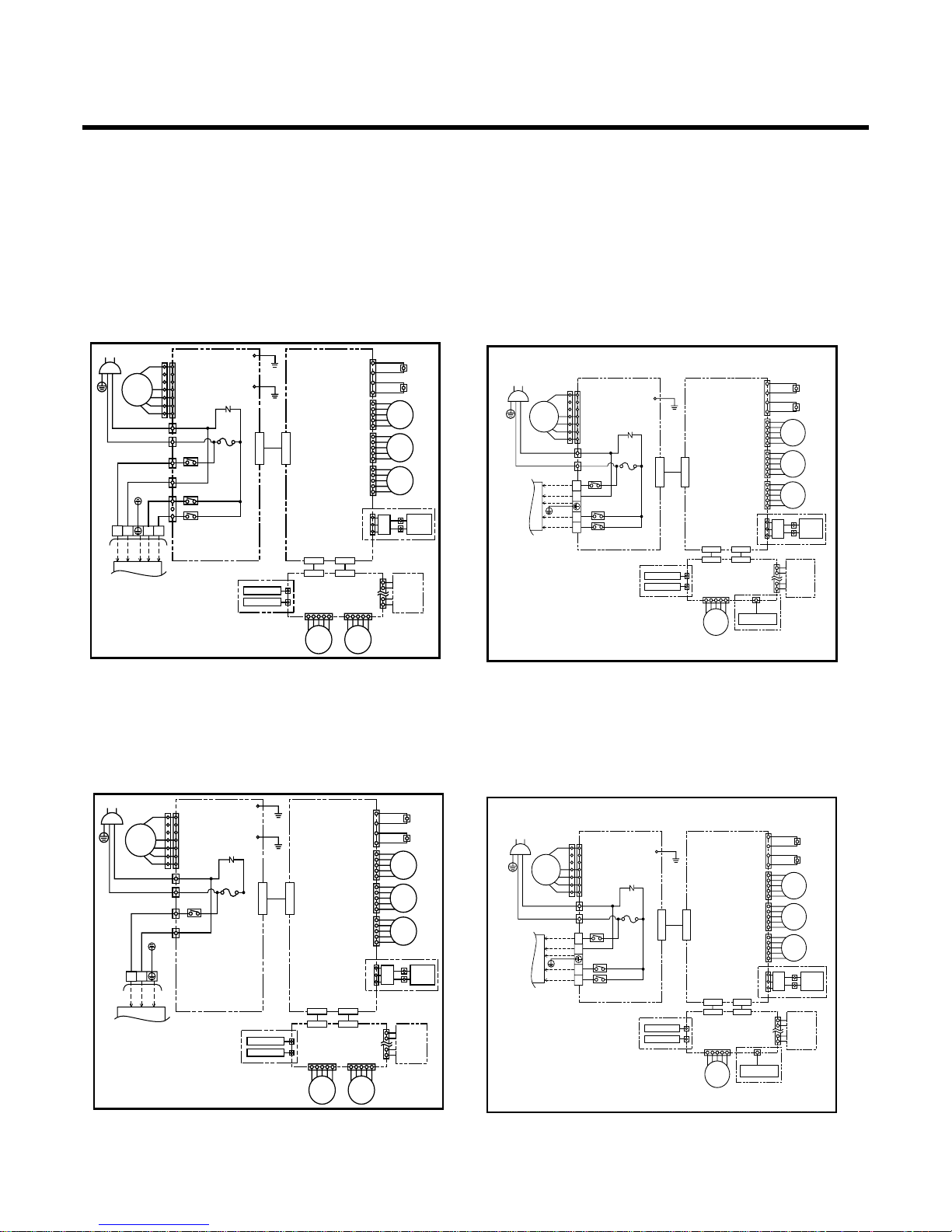
Wiring Diagram
-11-
INDOOR WIRING DIAGRAM
CONNECT
PCB ASM
DISPLAY
PCB
ASM
AC ASM DC ASM
CN-POW1
CN-GND2
CN-POW2
CN-TH1CN-UDCN-LR1CN-LR2
CN-MOTOR1
CN-OUT
RY-COMP
RY-4WAY
RY-FAN
CN-COMP
CN-4WAY
/FAN
PLASMA
AIR CLEAN
FUSE
250V 3.15A
ZNR
CN-D1 CN-D2
POWER
BR(Plained)
BK
BL
WH
BK
YL
RD
RD
BL(Ribbed)
FAN
MOTOR
STEP
MOTOR
STEP
MOTOR
STEP
MOTOR
STEP
MOTOR
STEP
MOTOR
TO OUTDOOR UNIT
SAFETY S/W
SAFETY S/W
BR
BL
GN/YL
BRBLGN/YLBKRD
BK
RD
1(L) 2(N)
3854A20246C
34
CN-GND1
CN-ACDC1
CN-ACDC2
CN-HVB
H.V.
ASM
CONNECT
PCB ASM
DISPLAY
PCB
ASM
AC PWB ASM DC PWB ASM
CN-POW1
CN-POW2
43
CN-TH1(WH)
CN-UD(BL)CN-LR1(WH)CN-LR2(WH)
CN-MOTOR1
RY-COMP
RY-4WAY
RY-FAN
T/BLOCK
PLASMA
AIR CLEAN
FUSE
250V 3.15A
ZNR
CN-D1(WH) CN-D2(WH)
POWER
BR(Plained)
BK
BL
WH
BK
YL
RD
RD
BL(Ribbed)
FAN
MOTOR
STEP
MOTOR
STEP
MOTOR
STEP
MOTOR
STEP
MOTOR
FORCE S/W
TO OUTDOOR UNIT
SAFETY S/W
SAFETY S/W
BR
BL
GN/YL
BK
RD
1(L) 2(N)
3854A20374A
34
CN-GND1
CN-ACDC1
CN-ACDC2
CN-HVB(BL)
H.V.
ASM
(1) Indoor Unit
1. Heating Model
2. Cooling Model
AS-H096PBC0
AS-H096PDC0
AS-H096PMC0
AS-H126PBC0
AS-H126PDC0
AS-H126PMC0
LS-H096PBC0
LS-H096PDC0
LS-H096PMC0
LS-H126PBC0
LS-H126PDC0
LS-H126PMC0
AS-H096PWL1
LS-H096PBL1
LS-H096PDL1
LS-H096PML1
INDOOR WIRING DIAGRAM
CONNECT
PCB ASM
DISPLAY
PCB
ASM
DC ASM
CN-TH1CN-UDCN-LR1CN-LR2
PLASMA
AIR CLEAN
CN-D1 CN-D2
BK
RD
STEP
MOTOR
STEP
MOTOR
STEP
MOTOR
STEP
MOTOR
STEP
MOTOR
SAFETY S/W
SAFETY S/W
3854A20246D
CN-HVB
H.V.
ASM
AC ASM
CN-POW1
CN-POW2
RY-COMP
CN-OUT
CN-COMP
FUSE
250V 3.15A
ZNR
POWER
BR(Plained)
BK
BL
WH
YL
RD
BL(Ribbed)
FAN
MOTOR
TO OUTDOOR UNIT
BR
BL
GN/YL
BRBLGN/YL
1(L) 2(N)
CN-GND2
CN-MOTOR1
CN-GND1
CN-ACDC1
CN-ACDC2
CONNECT
PCB ASM
DISPLAY
PCB
ASM
AC PWB ASM DC PWB ASM
CN-POW1
CN-POW2
43
CN-TH1(WH)
CN-UD(BL)CN-LR1(WH)CN-LR2(WH)
CN-MOTOR1
RY-COMP
RY-4WAY
RY-FAN
T/BLOCK
PLASMA
AIR CLEAN
FUSE
250V 3.15A
ZNR
CN-D1(WH) CN-D2(WH)
POWER
BR(Plained)
BK
BL
WH
BK
YL
RD
RD
BL(Ribbed)
FAN
MOTOR
STEP
MOTOR
STEP
MOTOR
STEP
MOTOR
STEP
MOTOR
FORCE S/W
TO OUTDOOR UNIT
SAFETY S/W
SAFETY S/W
BR
BL
GN/YL
BK
RD
1(L) 2(N)
3854A20374C
34
CN-GND1
CN-ACDC1
CN-ACDC2
CN-HVB(BL)
H.V.
ASM
LS-C126PBC0
LS-C126PDC0
LS-C126PMC0
LS-C126PBL1
LS-C126PDL1
LS-C126PML1
LS-C126PWL1
-12-
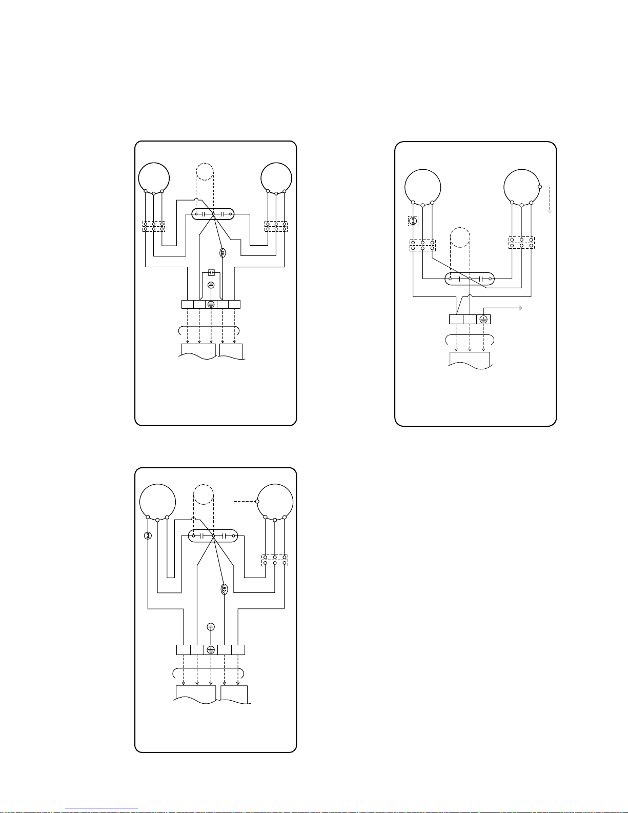
(2) Outdoor Unit
1. Heating Model 2. Cooling Model
COMP
C
S
R
FAN
MOTOR
BR RD BL
BR BL
BK(RD
)
YL
GN/YL
BR BL BK RD
GN/YL
BL BL
REVERSING
CAPACITOR
VALVE
RD BL YL
BL
BK(RD)
CAPACITOR
RD
BR
RD
BL
YL
TO INDOOR UNIT
OUTDOOR WIRING DIAGRAM
3854A20051W
TERMINAL
BLOCK
HCF
PTC
1(L)2(N
)
34
COMP
C
S
R
FAN
MOTOR
OLP
BRBRRD BL
BR RD
BL
BL
GN/YL
BR BL
GN/YL
BL BL
RD BL YL
GN/YL
CAPACITOR
BR
RD
BL
YL
TO INDOOR UNIT
OUTDOOR WIRING DIAGRAM
3854A30077B
TERMINAL
BLOCK
HCF
PTC
1(L)2(N
)
AS-H126PBC0
AS-H126PDC0
AS-H126PMC0
LS-H126PBC0
LS-H126PDC0
LS-H126PMC0
LS-C126PBC0
LS-C126PBL1
LS-C126PDC0
LS-C126PDL1
LS-C126PMC0
LS-C126PML1
LS-C126PWL1
COMP
C
S
R
FAN
MOTOR
OLP
BR RD BL
BR BL
BK(RD)
YL
GN/YL
BR BL BK RD
GN/YL
BL BL
REVERSING
VALVE
RD BL YL
GN/YL
BK(RD)
CAPACITOR
RD
BL
YL
TO INDOOR UNIT
OUTDOOR WIRING DIAGRAM
3854A30077D
TERMINAL
BLOCK
HCF
PTC
1(L)2(N
)
34
AS-H096PBC0
AS-H096PDC0
AS-H096PMC0
AS-H096PWL1
LS-H096PBC0
LS-H096PBL1
LS-H096PDC0
LS-H096PDL1
LS-H096PMC0
LS-H096PML1

Operation Details
1. MAIN UNIT FUNCTION
• DISPLAY
1) C/O Model
Operation Indicator
• ON while in appliance operation, OFF while in appliance pause.
• Flashing while in disconnection or short in Thermistor. (3 sec off / 0.5 sec on)
Sleep Timer Indicator
• ON while in sleep timer mode, OFF when sleep timer cancel or appliance operation pause.
Timer Indicator
• ON while in timer mode (on/off), OFF when timer mode is completed or canceled.
Comp. Running Incidator
• While in appliance operation, ON while in outdoor unit compressor running, OFF while in compressor off.
2) H/P Model
Operation Indicator
• ON while in appliance operation, OFF while in appliance pause.
• Flashing while in disconnection or short in Thermistor. (3 sec off / 0.5 sec on)
Sleep Timer Indicator
• ON while in sleep timer mode, OFF when sleep timer cancel or appliance operation pause.
Timer Indicator
• ON while in timer mode (on/off), OFF when timer mode is completed or canceled.
Defrost Indicator
• OFF except when hot start during heating mode operation or while in defrost control.
■ Cooling Mode Operation
• When the intake air temperature reaches 0.5°C below the setting temp, the compressor and the outdoor fan
stop.
• When it reaches 0.5°C above the setting temp, they start to operate again.
Compressor ON Temp ➲ Setting Temp+0.5°C
Compressor OFF Temp ➲ Setting Temp-0.5°C
• While in compressor running, operating with the airflow speed set by the remote control. While in compressor
not running, operating with the low airflow speed regardless of the setting.
■ Healthy Dehumidification Mode
• When the dehumidification operation input by the remote control is received, the intake air temperature is
detected and the setting temp is automatically set according to the intake air temperature.
26°C ≤ Intake Air Temp ➲ 25°C
24°C ≤ Intake Intake Air Temp<26°C ➲ Intake Air Temp-1°C
18°C ≤ Intake Intake Air Temp<24°C ➲ Intake Air Temp-0.5°C
Intake Air Temp<18°C ➲ 18°C
-13-

• While in compressor off, the indoor fan repeats low airflow speed and pause.
• While the intake air temp is between compressor on temp. and compressor off temp., 10-min dehumidifica-
tion operation and 4-min compressor off repeat.
Compressor ON Temp. ➲ Setting Temp+0.5°C
Compressor OFF Temp. ➲ Setting Temp-0.5°C
• In 10-min dehumidification operation, the indoor fan operates with the low airflow speed.
■ Heating Mode Operation
• When the intake air temp reaches +3°…above the setting temp, the compressor is turned off. When below
the setting temp, the compressor is turned on.
Compressor ON Temp. ➲ Setting Temp.
Compressor OFF Temp. ➲ Setting Temp.+3°C
• While in compressor on, the indoor fan is off when the indoor pipe temp. is below 20°C, when above 28°C , it
operates with the low or setting airflow speed. When the indoor pipe temp is between 20°C and 28°C, it operates with Super-Low(while in sleep mode, with the medium airflow speed).
• While in compressor off, the indoor fan is off when the indoor pipe temp is below 33°C, when above 35°C , it
operates with the low airflow speed.
• If overloaded while in heating mode operation, in order to prevent the compressor from OLP operation, the
outdoor fan is turned on/off according to the indoor pipe temp.
• While in defrost control, both of the indoor and outdoor fans are turned off.
■ Defrost Control
• While in heating mode operation in order to protect the evaporator pipe of the outdoor unit from freezing,
reversed to cooling cycle to defrost the evaporator pipe of the outdoor unit.
• After 40 min heating mode operation, at 4 min interval, whether to carry out defrost control or not and the time
of defrost control are determined according to the following conditions.
1) While in heating mode operation, the maximum of the indoor pipe temperature is measured and it is com-
pared with the present indoor pipe temperature to get the difference of the indoor pipe temperatures (=the
maximum temperature of indoor pipe ? the present temperature of indoor pipe), according to which, whether
to carry out defrost control or not is determined.
2) According to the need of defrost control shown above and the elapsed time of heating mode operation at that
moment, the defrost control time is determined.
3) When the determined time of defrost control is below 7 min, heating mode operation continues without carry-
ing out defrost control. According to the procedure stated above, the determination is made again. When the
defrost control time is 7 min or longer, defrost control is then carried out.
• While in defrost control, the minimum temp of the indoor pipe is measured and it is compared with the present
temp of the indoor pipe to get the difference of the indoor pipe temperatures (=the present temperature of the
indoor pipe ? the minimum temperature of the indoor pipe). When the difference is 5°C or higher, defrost control is completed and heating mode operation is carried out.
• While in defrost control, if the defrost time determined before the start of defrost control is completed, defrost
control stops and heating mode operation is carried out regardless of the above condition.
• When the indoor pipe temp is 42°C or above, defrost control is not carried out even if the condition is one of
the defrost conditions above.
• While in defrost control, the compressor is on and the indoor fan, the outdoor fan, and the 4 way valve are off.
-14-

-15-
■ Fuzzy Operation (C/O Model)
• According to the temperature set by Fuzzy rule, when the intake air temp is 0.5°C or more below the setting
temp, the compressor is turned off. When 0.5°C or more above the setting temp, the compressor is turned on.
Compressor ON Temp ➲ Setting Temp + 0.5°C
Compressor OFF Temp ➲ Setting Temp + 0.5°C
• At the beginning of Fuzzy mode operation, the setting temperature is automatically selected according to the
intake air temp at that time.
26°C ≤ Intake Air Temp ➲ 25°C
24°C ≤ Intake Air Temp < 26°C ➲ Intake Air Temp + 1°C
22°C ≤ Intake Air Temp < 24°C ➲ Intake Air Temp + 0.5°C
18°C ≤ Intake Air Temp < 22°C ➲ Intake Air Temp
Intake Air Temp<18°C ➲ 18°C
• When the Fuzzy key (Temperature Control key) is input after the initial setting temperature is selected, the
Fuzzy key value and the intake air temperature at that time are compared to select the setting temperature
automatically according to the Fuzzy rule.
• While in Fuzzy operation, the airflow speed of the indoor fan is automatically selected according to the
temperature.
■ Fuzzy Operation (H/P Model)
• When any of operation mode is not selected like the moment of the power on or when 3 hrs has passed since
the operation off, the operation mode is selected.
• When determining the operation mode, the compressor, the outdoor fan, and the 4 way valve are off and only
the indoor fan is operated for 15 seconds. Then an operation mode is selected according to the intake air
temp at that moment as follows.
24°C ≤ Inatake Air Temp ➲ Fuzzy Operation for Cooling
21°C ≤ Inatake Air Temp<24°C ➲ Fuzzy Operation for Dehumidification
Inatake Air Temp<21°C ➲ Fuzzy Operation for Heating
• If any of the operation modes among cooling / dehumidification / heating mode operations is carried out for 10
sec or longer before Fuzzy operation, the mode before Fuzzy operation is operated.
1) Fuzzy Operation for Cooling
• According to the setting temperature selected by Fuzzy rule, when the intake air temp is 0.5°C or more below
the setting temp, the compressor is turned off. When 0.5°C or more above the setting temp, the compressor
is turned on.
Compressor ON Temp ➲ Setting Temp +0.5°C
Compressor OFF Temp ➲ Setting Temp + 0.5°C
• At the beginning of Fuzzy mode operation, the setting temperature is automatically selected according to the
intake air temp at that time.
26°C≤ Intake Air Temp ➲ 25°C
24°C≤ Intake Air Temp<26°C ➲ Intake Air Temp + 1°C
22°C≤ Intake Air Temp<24°C ➲ Intake Air Temp + 0.5°C
18°C≤ Intake Air Temp<22°C ➲ Intake Air Temp
Intake Air Temp<18°C ➲ 18°C
• When the Fuzzy key (Temperature Control key) is input after the initial setting temperature is selected, the
Fuzzy key value and the intake air temperature at that time are compared to select the setting temperature
automatically according to the Fuzzy rule.
• While in Fuzzy operation, the airflow speed of the indoor fan is automatically selected according to the temperature.

-16-
2) Fuzzy Operation for Dehumidification
• According to the setting temperature selected by Fuzzy rule, when the intake air temp is 0.5°C or more below
the setting temp, the compressor is turned off. When 0.5°C or more above the setting temp, the compressor
is turned on.
Compressor ON Temp ➲ Setting Temp + 0.5°C
Compressor OFF Temp ➲ Setting Temp+0.5°C
• At the beginning of Fuzzy mode operation, the setting temperature is automatically selected according to the
intake air temp at that time.
26°C ≤ Intake Air Temp ➲ 25°C
24°C ≤ Intake Air Temp<26°C ➲ Intake Air Temp+1°C
22°C ≤ Intake Air Temp<24°C ➲ Intake Air Temp+0.5°C
18°C ≤ Intake Air Temp<22°C ➲ Intake Air Temp
Intake Air Temp<18°C ➲ 18°C
• When the Fuzzy key (Temperature Control key) is input after the initial setting temperature is selected, the
Fuzzy key value and the intake air temperature at that time are compared to select the setting temperature
automatically according to the Fuzzy rule.
• While in Fuzzy operation, the airflow speed of the indoor fan repeats the low airflow speed or pause as in
dehumidification operation.
3) Fuzzy Operation for Heating
• According to the setting temperature selected by Fuzzy rule, when the intake air temp is 3°C or more above
the setting temp, the compressor is turned off. When below the setting temp, the compressor is turned on.
Compressor ON Temp ➲ Setting Temp
Compressor OFF Temp ➲ Setting Temp + 3°C
• At the beginning of Fuzzy mode operation, the setting temperature is automatically selected according to the
intake air temp at that time.
20°C≤Intake Air Temp ➲ Intake Air Temp + 0.5°C
Intake Air Temp<20°C ➲ 20°C
• When the Fuzzy key (Temperature Control key) is input after the initial setting temperature is selected, the
Fuzzy key value and the intake air temperature at that time are compared to select the setting temperature
automatically according to the Fuzzy rule.
• While in Fuzzy operation, the airflow speed of the indoor fan is set to the high or the medium according to the
intake air temperature and the setting temperature.
■ Airflow Speed Selection
• The airflow speed of the indoor fan is set to high, medium, low, or chaos (auto) by the input of the airflow
speed selection key on the remote control.
■ On-Timer Operation
• When the set time is reached after the time is input by the remote control, the appliance starts to operate.
• The timer LED is on when the on-timer is input. It is off when the time set by the timer is reached.
• If the appliance is operating at the time set by the timer, the operation continues.
■ Air Cleaner Operation
• When an air cleaner function is selected during Air Conditioner operation.
- Plasma air cleaner function will be operated while in any operation mode with selecting the function.
- The function is to be stopped while it is operating with selecting the function.
• When an air cleaner function is selected during operation off.
- The function will be nly operated.
• When inlet grille of air conditioner is opened during plasma operation, High Voltage Generator(H.V.B) is to be
stopped. When inlet grille of air conditioner is closed during plasma operation, High Voltage Generator (H.V.B)
will be operated again.
-17-
■ Off-Timer Operation
• When the set time is reached after the time is input by the remote control, the appliance stops operating.
• The timer LED is on when the off-timer is input. It is off when the time set by the timer is reached.
• If the appliance is on pause at the time set by the timer, the pause continues.
■ Off-Timer ↔ On-Timer Operation
• When the set time is reached after the on/off time is input by the remote control, the on/off-timer operation is
carried out according to the set time.
■ Sleep Timer Operation
• When the sleep time is reached after <1,2,3,4,5,6,7,0(cancel) hr> is input by the remote control while in appli-
ance operation, the operation of the appliance stops.
• While the appliance is on pause, the sleep timer mode cannot be input.
• While in cooling mode operation, 30 min later since the start of the sleep timer, the setting temperature
increases by 1°C. After another 30 min elapse, it increases by 1°C again.
• When the sleep timer mode is input while in cooling cycle mode, the airflow speed of the indoor fan is set to the
low.
• When the sleep timer mode is input while in heating cycle mode, the airflow speed of the indoor fan is set to
the medium.
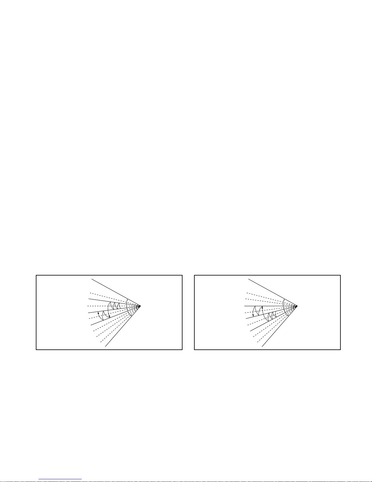
■ Chaos Swing Mode
• By the Chaos Swing key input, the louvers vane automatically operate with the Chaos Swing or they are fixed
to the desired direction.
• While in Chaos Swing mode, the angles of cooling and heating cycle operations are different.
■ Jet Cool Mode Operation (C/O Model)
• If the Jet Cool key is input at any operation mode while in appliance operation, the Jet Cool mode operates.
• In the Jet Cool mode, the indoor fan is operated at super-high speed for 30 min at cooling mode operation.
• In the Jet Cool mode operation, the room temperature is controlled to the setting temperature, 18°C
• When the sleep timer mode is input while in the Jet Cool mode operation, the Jet Cool mode has the priority.
• During the JET COOL function at any moment, the A/C starts to blow the cool air with side louvers closed at
extremely high speed for 30 minutes setting the room temp. automatically to 18°C.
CLOSED
OPEN
< Cooling Mode >
CLOSED
OPEN
< Heating Mode >

-18-
■ Jet Cool Mode Operation (H/P Model)
• While in heating mode or Fuzzy operation, the Jet Cool key cannot be input. When it is input while in the other
mode operation (cooling, dehumidification, ventilation), the Jet Cool mode is operated.
• In the Jet Cool mode, the indoor fan is operated at super-high speed for 30 min at cooling mode operation.
• In the Jet Cool mode operation, the room temperature is controlled to the setting temperature, 18°C.
• When the sleep timer mode is input while in the Jet Cool mode operation, the Jet Cool mode has the priority.
• During the JET HEAT function at any moment, the A/C starts to blow the hot air with side louvers closed at
extremely high speed for 60 minutes setting the room temp. automatically to 30°C.
■ Forced Operation
• Operation procedures when the remote control can't be used.
• The operation will be started if the power button is pressed.
• If you want to stop operation, re-press the button.
• While in forced operation, the key input by the remote control has no effect and the buzzer sounds 10 times to
indicate the forced operation.
■ Test operation
•
During the TEST OPERATION, the unit operates in cooling mode at high speed fan, regardless of room temperature and resets in 18±1 minutes.
•
During test operation, if remote controller signal is received, the unit operates as remote controller sets.
If you want to use this operation, open the front panel upward and Press the power button let it be pressed for
about 3 seconds.
•
If you want to stop the operation, re-press the button.
■ Auto restart
•
In case the power comes on again after a power failure, Auto Restarting Operation is the function to operate
procedures automatically to the previous operating conditions.
■ Remote Control Operation Mode
• When the remote control is selected by the slide switch on the main unit, the appliance operates according to
the input by the remote control.
■ Protection of the evaporator pipe from frosting
• If the indoor pipe temp is below 0°C in 7 min. after the compressor operates without any pause while in cool-
ing cycle operation mode, the compressor and the outdoor fan are turned off in order to protect the indoor
evaporator pipe from frosting.
• When the indoor pipe temp is 7°C or higher after 3 min. pause of the compressor, the compressor and the
outdoor fan is turned on according to the condition of the room temperature.
■ Buzzer Sounding Operation
• When the appliance-operation key is input by the remote control, the short "beep-beep-" sounds.
• When the appliance-pause key is input by the remote control, the long "beep—" sounds.
• When a key is input by the remote control while the slide switch on the main unit of the appliance is on the
forced operation position, the error sound "beep-beep-beep-beep-beep-" is made 10 times to indicate that the
remote control signal cannot be received.
Heat pump Model
Cooling Model
Room Temp. ≥24°C21°C ≤Room Temp. < 24°C Room Temp. < 21°C
Operating mode Cooling Cooling Health y Dehumidification Heating
Indoor FAN Speed
High High High High
Setting Temperature
22°C22°C23°C24°C
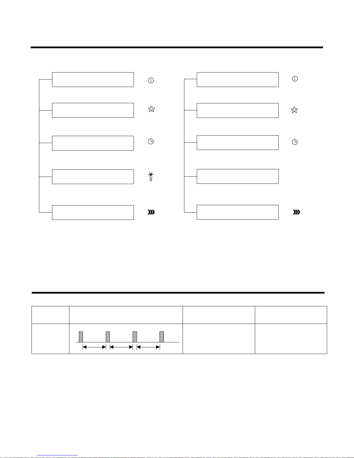
Display Function
-19-
Self-diagnosis Function
3sec 3sec 3sec
(once)
Error
Code
1
Error Display LED
(Indoor body operation LED)
Error contents
• Indoor room temperature
thermistor open/short
• Indoor pipe temperature
thermistor open/short.
• Indoor Thermistor
assembly check
SVC check point
1. Heating Model 2. Cooling Model
• Cooling, Soft Dry, Fan, Heating • Cooling, Soft Dry, Fan
• Sleep Mode • Sleep Mode
• Timer Mode • Timer Mode
• Hot-start, Defrost
• PLASMA Air Purifier • PLASMA Air Purifier
Operation Indicator
Timer Indicator
Sleep Timer Indicator
Defrost Indicator
Operation Indicator
Timer Indicator
Sleep Timer Indicator
Compressor on Indicator
PLASMA
PLASMA
OUTDOOR
 Loading...