

Page 1

ENGLISH
FRANCAIS
ESPAÑOL
INSTALLATION MANUAL
AIR CONDITIONER
• Please read this installation manual completely before installing the product.
• Installation work must be performed in accordance with the national wiring
standards by authorized personnel only.
• Please retain this installation manual for future reference after reading it
thoroughly.
TYPE : VENTILATOR
© LG Electronics U.S.A., Inc., Englewood Cliffs,
NJ. All rights reserved. “LG Life’s Good” is a
registered trademark of LG Corp.
http://www.lghvac.com
www.lg.com
P/NO : 3828A20469L
Page 2
ERV Installation Instructions
Please read these instructions completely before installing the product.
Failure to carefully read and follow all instructions in this manual can result in equipment malfunction,
property damage, personal injury and/or death.
Page 3

Ventilator Installation Manual
TABLE OF CONTENTS
Installation Manual 3
ENGLISH
Safety Precaution.................4
Introduction ..........................7
Symbols Used in
this manual ..........................7
Feature Dimension
Diagram...............................7
Installation ............................9
Installation Map ...................9
Installation of Main Body ...11
Connection of Duct............11
Method to Connect
Power Cord .......................13
Conduit connection............14
Group control.....................15
How to connect Central
Controller(Accessory) .......17
In case of finding a problem
at a trial operation..............18
• Screws
• Nuts
• Ceiling Fixing Bolt(M10~12)
• Washer
• Aluminium Tape
• Screws
• Screw Driver
• Spanner
• Cutter
• Cutter
• Screw Driver
Installation
Requirements
Required Parts Required Tools
Page 4
Safety Precautions
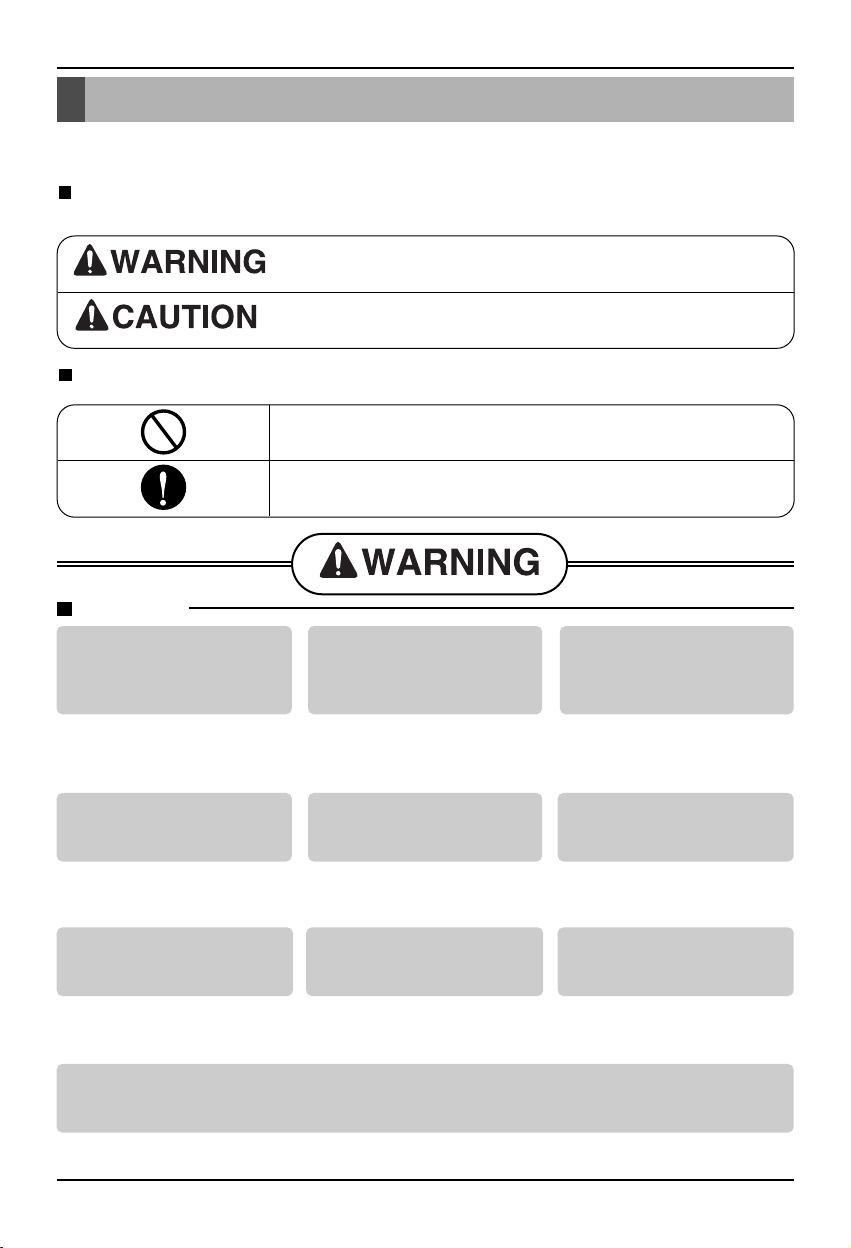
Safety Precautions
To prevent injury to the user or other people and property damage, the following instructions
must be followed.
Incorrect operation due to ignoring instruction will cause harm or damage. The seriousness is
classied by the following indications.
This symbol indicates the possibility of death or serious injury.
This symbol indicates the possibility of injury or damage.
Meanings of symbols used in this manual are as shown below.
Be sure not to do.
Be sure to follow the instruction.
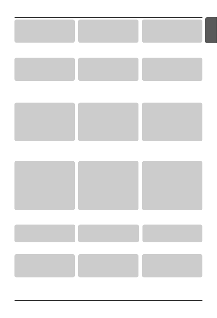
Installation
Do not use a defective or
underrated circuit breaker.
Use this appliance on a
dedicated circuit.
• There is risk of re or electric
shock.
For electrical work, contact
the dealer, seller, a qualied
electrician, or an Authorized
Service Center.
• Do not disassemble or repair the
product. There is risk of re or
electric shock.
Always ground the product.
• There is risk of re or electric
shock.
Install the panel and the
cover of control box
Always install a dedicated
circuit and breaker.
Use the correctly rated
breaker or fuse.
securely.
• Failure to use correctly rated breakers
or fuse may cause re or electric shock.
Do not modify or extend the
power cable.
• There is risk of re or electric
shock.
Use a vacuum pump or Inert (nitrogen) gas when doing leakage test or air purge. Do not
compress air or Oxygen and Do not use Flammable gases. Otherwise, it may cause re or
explosion.
• There is the risk of death, injury, re or explosion.
• Improper wiring or installation
may cause re or electric shock
Do not install, remove, or reinstall the unit by yourself
(customer).
• There is risk of re, electric
shock, explosion, or injury.
• Failure to use correctly rated breakers
or fuse may cause re or electric shock.
Be cautious when unpacking
and installing the product.
• Sharp edges could cause injury.
4 Ventilator
Page 5
Installation Manual 5
ENGLISH
Safety Precautions
For installation, always
contact the dealer or an
Authorized Service Center.
• There is risk of fire, electric
shock, explosion, or injury.
Do not install the product on a
defective installation stand.
• It may cause injury, accident, or
damage to the product.
Do not let the product run for a
long time when the humidity is
very high and a door or a
window is left open.
• Moisture may condense and wet
or damage furniture.
For re-installation of the
installed product, always
contact the dealer or an
Authorized Service Center.
• There is risk of fire, electric shock,
explosion or injury.
Do not open the
maintenance cover of the
main body during operation.
• Otherwise, it may cause electrical
shock.
Use the outdoor air suction
hole with the net installed to
ensure that birds could not
come in.
• Remove estrange things like the
bird’s nest. Otherwise, it may
cause scarcity of indoor oxygen.
Install the air intake where
polluted air can not be
directly sucked in.
•
It may cause various accidents,
including suffocation, due to the
suction of harmful gasses(CO, etc.)
Do not install this product in
a refrigerated warehouse,
heated swimming pool or
other location where the
temperature and humidity
are significantly different.
• There is risk of electrical shock,
malfunctioning.
Install this product in an
environment where the
temperature ranges from –10°C to
+45°C and the relative humidity is
less than 80%. It condensation is
expected to form, heat up the fresh
outside air using a duct heater etc.
Install this product in and
environments where the outside
air intake meets the following
conditions: temperature range
is between –15°C and +40°C and
the relative humidity is 80% or
less.
Use the designated electrical
wires for the terminal board
connections, and connect the
wires securely so that they will
not become disconnected.
(Failure to ensure proper
connections may cause fire.)
When passing metal ducts
through wooden buildings clad
with metal laths, wire laths or
metal, these ducts must be
installed in such a way that they
will not make electrical contact
with the metal laths, wire laths
or metal sheets. (Power leakage
can cause ignition)
Avoid fire equipment
• There is risk of fire.
When the product is soaked
(flooded or submerged), contact
an Authorized Service Center.
• There is risk of fire or eletric shock.
Don't touch a dedicated circuit
or breaker with wet hands.
• There is risk of electric shock.
■ Operation
When the product is not be
used for a long time,
disconnect the power supply
plug or turn off the breaker.
• There is risk of product damage or
failure, or unintended operation.
Do not store or use flammable
gas or combustibles near the
product.
• There is risk of fire or failure of
product.
When flammable gas leaks,
turn off the gas and open a
window for ventilation
before turn the product on.
• Do not use the telephone or
turn switches on or off.
There is risk of explosion or fire
Page 6

Safety Precautions
Be cautious that water could not enter the
product.
• If water enters the product, there is risk of re, electric
shock, or product damage.
The outside ducts must be tilted at a gradient
(1/30 or more) down toward the outdoor area
from the ventilator unit, and properly insulated.
(The entry of rain water may cause power
leaks, re or damage to household property.)
Installation
Don't connect the ground wire
to the window frame or water
cock.
• There is risk of electric shock.
Keep level even when
installing the product.
• To avoid vibration or water
leakage.
Do not install the product at a
smoky and oily place like
kitchen or factory.
• Otherwise. oil may adhere to the
lter or heating exchanger and cause
trouble.
Use two or more people to
lift and transport the
product.
• Avoid personal injury.
Turn the breaker o when cleaning or
maintaining the product.
• There is risk of electric shock, if product is cleaned while the
breaker is on.
Glove should be worn when doing the
installation work. (There is risk of injury.)
Install the product in an
insulated space from outdoor
air.
• If the product is installed outside of the
insulated layer, dewing occurs inside of
the main body in winter and it causes
electrical shock or falling of condensed
water.
Do not install the product where
it will be exposed to sea wind
(salt spray) directly.
• It may cause corrosion on the
product. Corrosion, particularly on
the condenser and evaporator ns,
could cause product malfunction or
inefficient operation.
Operation
Use a soft cloth to clean. Do
not use harsh detergents, wax
or thinner, etc.
• Otherwise, color or surface of the
oroduct mav deteriorate.
Do not block the inlet or outlet of air ow.
• It may cause product failure.
6 Ventilator
Clean the lter and the heat
exchanger regularly and use
the gloves for cleaning.
• Accumulation of dust or debris
causes the deterioration of air volume.
Do not use the product for special
purposes, such as preserving
foods, works of art, etc. It is a
consumer ventilator, not a
precision refrigeration system.
• There is risk of damage or loss of
property.
Do not step on or put anyting on the product.
• There is risk of personal injury and failure of product.
Page 7

Introduction
Air Filter
(Outdoor
Introduction
While using the remote controller , refer to attached remote controller manual
Symbols used in this Manual
This symbol alerts you to the risk of electric shock.
This symbol alerts you to hazards that could cause harm to the
product.
NOTICE
Feature Dimension Diagram
Model : LZ-H080GBA2 [ARVU053ZEA2]/ LZ-H100GBA2 [ARVU063ZEA2]
This symbol indicates special notes.
Blower for Exhausting Air
EA
(Exhaust Air)
OA
Air)
Suspension Fixture
(Return Air)
(Supply Air)
Blower for
Supplying Air
RA
SA
ENGLISH
F
C
Total Heat Exchange Element
Maintenance Cover
Control box
Unit : mm(inch)
Model
LZ-H080GBA2[ARVU053ZEA2]
LZ-H100GBA2[ARVU063ZEA2]
Figure Duct Pitch Weight
A B C D E F G H J K L kg (lb)
1062 1140 365 987 1176 180 250 242 253 98 513 481 67
(41.8) (44.9) (14.4) (38.9) (46.3) (7.1) (9.8) (9.5) (10) (3.9) (20.2) (18.9) (147.7)
Pitch of Suspension
Fixture
Nominal
Duct Connection Flange
Diameter
Service clearances for maintenance must be added to dimension diagram above, refer to product engineering
manual for required service clearances.
Installation Manual 7
Page 8

Introduction
Model : LZ-H150GBA2 [ARVU093ZFA2]/ LZ-H200GBA2 [ARVU123ZFA2]
D
O
RA
EA
B
N
E
SA
OA
C
Model
LZ-H150GBA2[ARVU093ZFA2]
LZ-H200GBA2[ARVU123ZFA2]
A B
1313
(51.7)
Maintenance Cover
M
L
K
Air Filter
Figure Weight
1140
(44.9)
Pitch of Suspension
C D E
738
987
(29.1)
(38.9)
Fixture
1176
(46.3)
F
339
(13.3)
Control Box
J
H
G
Total Heat Exchanger
Duct Connection Flange
G H J K L kg(lb)
242
(9.5)
253
(10)98(3.9)
340
(13.4)
Unit: mm(inch)
350
(13.8)
146
(321.9)
F
Service clearances for maintenance must be added to dimension diagram above, refer to product engineering
manual for required service clearances.
8 Ventilator
Page 9

Installation Manual 9
ENGLISH
Installation
Installation
Installation Map (LZ-H080GBA2 [ARVU053ZEA2]/ LZ-H100GBA2 [ARVU063ZEA2])
■
A PLANE FIGURE
■
A FRONT VIEW
■
THREE DIMENSION VIEW
■
INSTALLATION OF MAINTENANCE COVER
RA Grille
EA
OA
Duct slope: More than 1/30(wall side)
Obtaining of Right Distance
(Preventing Penetration of Rain Water)
New Type Hood
(Preventing Penetration of Rain Water)
EA
OA
* 1m = 39.4in
Ventilator
Maintenance Space
Inspection Hatch
Duct
Ventilator
1m or more 1m or more
Inspection Hatch
Ceiling Fixing Bolt(Supplied by installer)
SA
SA Grille
RA
RA GrilleSA Grille
Maintenance Cover
Control Box
SA Grille
EA
Ventilator
Main Body
OA
* 600mm = 23.6in
More than 600mm
Maintenance Space
600x600mm
Inspection Hatch
2
Page 10

10 Ventilator
Installation
Installation Map (LZ-H150GBA2 [ARVU093ZFA2]/ LZ-H200GBA2 [ARVU123ZFA2])
❘■
A PLANE FIGURE
❘■
A FRONT VIEW
Maintenance Cover
Control Box
SA Grille
❘■
THREE DIMENSION VIEW
❘■
INSTALLATION OF MAINTENANCE COVER
RA Grille
EA
OA
Duct slope: More than 1/30(wall side)
Obtaining of Right Distance
(Preventing Penetration of Rain Water)
New Type Hood
(Preventing Penetration
of Rain Water)
EA
OA
* 1m = 39.4in
Ventilator
1m or more
Inspection
Hatch
Maintenance
Space
Inspection
Hatch
Ceiling Fixing Bolt(Supplied by installer)
RA RA
1m or more
RA Grille
SA Grille
SA SA
SA Grille
EA
OA
* 600mm = 23.6in
Ventilator
Main Body
More than 600mm
Maintenance Space
600x600mm
Inspection Hatch
2
Page 11

Installation Manual 11
ENGLISH
Installation
Installation of Main Body
Assembly of Washer, Nut
Tighten the common washer and nut (more than 21mm
(0.83in) for the outside diameter of M10, to the
commercial ceiling fixing bolt (M10) as shown in the
right figure.
• For the ceiling fixing bolt, perform work less than
50mm(1.97in) under the ceiling fixing bracket.
Connection of Duct
1. After securely connect the duct with the duct connection flange, wrap it
with a commercial aluminium tape so that air cannot be leaked.
2. Adjust the duct from the ceiling so that no force is applied to the main
body of the ventilation system.
3. Always use two ducts at the outdoor with the heat insulating material for
prevention of dewing.
Duct
Taping
Ceiling Fixing Bolt
(M10)
Nut
Spring Washer
Washer
Nut
Page 12

12 Ventilator
Installation
Duct to OA
Main Body
Heat Insulating Material
Aluminium
Duct Connection Flange
Rapid Bending Excessive Bending
Too Close Bending
to Outlet
Rapid Reduction of
Duct Diameter
CAUTION:
• Check that there are no foreign
materials (paper, vinyl, etc) or cutoff
powders in the duct before connecting
the duct.
• Take care so that shock may not be
applied to the damper plate within the
main body when performing the duct
connection work.
• It is recommended to perform
adiabatic treatment even to the duct
pipe at the indoor side where ambient
temperature is expected higher than
room temperature when the main body
of the ventilation system for cooling in
summer.
• Take care so that work may not be
performed as in the left figure.
Otherwise, it may cause reduction of
air volume or abnormal noise.
CAUTION:
•
In -10℃ below ambient temperature, when ventilation is installed the equivalent space in
the outdoor and outdoor, It may cause condensation, you must install drainage
facilities(Drain Pan) and MD(Moterized Damper) at SA/RA duct.
Page 13

Installation Manual 13
ENGLISH
Installation
Cord Clamp
(L1) (L2)
PowerGND
GN/YL BR BL
Method to Connect Power Cord
1. Release two screws and then open
the cover of the control box.
•
With reference to the below wiring diagram,
accurately connect the main power cords into
the terminal block.
2. After inserting the power cord into the bushing,
fully insert it into the terminal block for connection.
• Fix the power cords with the clamp.
• Make sure that the power cords may not be removed by pulling them.
3. Wiring specifications
Wiring specifications
Sheathed wire(should be complied with IEC60245 standard)
NRTL recognized (UL, CSA, ETL ...)
Length MAX. 100m(109.4yd)
External contact specifications Normally closed contact (Current tolerance 10mA - 0.5A)
The Power cord connected to the unit should be selected according to the following specifications .
CAUTION
Cover of Control Box
Screw
Page 14

Installation
14 Ventilator
Conduit connection
1. Set the connecting cable into the terminal
block of indoor unit, and tighten set screw to
lock the conduit bracket to the indoor unit.
2. Join the conduit and the conduit bracket
together.
3. After connecting the remote controller wire ,
complete to use conduit
CAUTION: Must use the
elbow type (L-Type)
conduit.
Lock nut
Conduit
Conduit
bracket
• For wiring, use the designated power wire and connect firmly, then secure to prevent outside pressure
being exerted on the terminal block.
• Use an appropriate screwdriver for tightening the terinal screws. A screwdriver with a small head will
strip the head and make proper tighterning impossible.
• Over-tightening the terminal screws may break them.
When none are available, follow the instructions below.
• Do not connect wiring of different thicknesses to the power terminal block. (Slack in the power
wiring may cause abnormal heat.)
• When connecting wiring which is the same thickness, do as shown in the figure below.
◆
Precautions when laying power wiring
Round pressure terminal
Power wire
Use round pressure terminals for connections to the power terminal block.
Lock nut
Conduit
bracket
Conduit
Remote
controller
hole
Lock nut
Conduit
bracket
Conduit
Cord Clamp
Remote
controller hole
Page 15

Installation Manual 15
ENGLISH
Installation
GND
GND
12V
Signal wire
Signal wire
GND
12V
B Y R B Y R
MASTER SLAVE
Signal wire
GND
12V
Signal wire
Group control
1. When installing more than 2
units of air conditioner to one
wired remote controller, please
connect as the right figure.
• If it is not event communication
indoor unit, set the unit as slave.
• Check for event communication
through the product manual.
2. When installing more than 2 wired
remote controllers to one air
conditioner, please connect as the
right picture.
• When installing more than 2 units of wired
remote controller to one air conditioner, set
one wired remote controller as master and
the others all as slaves, as shown in the
right picture.
• You cannot control the group as shown in
the right for some products.
•
Refer to the product manual for more detail.
When controlling multiple indoor units with event communication function with one remote
controller, you must change the master/slave setting from the indoor unit.
- Indoor units, the master/slave configuration of the product after completion of indoor unit power
‘OFF’ and then ‘ON’ the power after 1 minutes elapsed sign up.
- For ceiling type cassette and duct product group, change the switch setting of the indoor PCB.
- For wall-mount type and stand type product, change the master/slave setting with the wireless
remote controller. (Refer to wireless remote controller manual for detail)
❈ When installing 2 remote controllers to one indoor unit with event communication function, set
the master/slave of the remote controller. (Refer to remote controller master/slave selection)
When controlling the group, some functions excluding basic operation setting, fan level
Min/Mid/Max, remote controller lock setting and time setting may be limited.
<When simultaneously connecting
2 sets of wired remote controller>
• When controlling in groups, set the master/slaver of the remote controller. Refer to
Installer setting section on how to set master/slave for more detail.
#1 switch OFF: Master
(Factory default setting)
#1 switch ON: Slave
ON
12345678
ON
12345678
Page 16

Installation
16 Ventilator
GND
SIGNAL
Combined operated system
Communication line
LGAP Network System
12V
PI485
Independent system
PI485
Communication line
LGAP Network System
•
This unit can be used as part of the combined operation system used together with indoor
units(Multi-V system air conditioners), or as an independent system for processing outside air.
<Combined operation system with Multi-V system(connected with ventilation units and
standard indoor units in a single refrigerant circuit)>
<Independent system (connected only with a ventilation unit in a single refrigerant circuit)>
Page 17

Installation Manual 17
ENGLISH
How to connect Central Controller(Accessory)
1. Connect between PI485 Gate Way(CN-OUT) and Main PCB(CN-CC).
2. You do not need to set the Option Switch of Main PCB.
3. Please refer to the manual of Accessory for the detail installation method.
How to connect Central Controller(Accessory)
CN-OUT
C N-C C
PI485 Gate Way
Main P C B
Central controller
Page 18

18 Ventilator
In case of finding a problem at a trial operation
In case of finding a problem at a trial operation
Symptom Counter-measures
The product doesn’t work
though you press the ‘ON’
switch.
The fan doesn't run
• Checking the power(rated power 1 phase, 208V/230V, the
diameter ø0.6~ø2.0, capacity of breaker)
• Isn’t the fuse connected?
• Are the PCB and Remote Controller rightly connected?
• Is the outdoor temperature the limit temperature?
(Less than -10°C(14°F), more than 45°C(113°F))
• In case of the limit temperature
- Switch on Option No. 5.
- Repower the product and check whether it works or not.
- Switch off Option No. 5. and repower the product once again.
Page 19

 Loading...