

LG ARNU24GVJA2 INSTALLATION MANUAL

INSTALLATION MANUAL
AIR CONDITIONER
• Please read this installation manual completely before installing the product.
• Installation work must be performed in accordance with the national wiring
standards by authorized personnel only.
• Please retain this installation manual for future reference after reading
it thoroughly.
P/NO : MFL42803111
www.lg.com
TYPE: Ceiling Suspended
ENGLISH ITALIANO
ESPAÑOL FRANÇAIS
DEUTSCH
PORTUGUÊS
кмллдавьбхд

2 Indoor Unit
Ceiling Suspended Convertable Type Indoor Unit Installation Manual
TABLE OF CONTENTS
o Installation guide map
o Four type "A" screws & plastic
anchors
o Connecting cable
o Pipes: Gas side
Liquid side
(Refer to Product
Data)
o Insulation materials
o Level gauge
o Screw driver
o Electric drill
o Hole core drill
o Horizontal meter
o Flaring tool set
o Specified torque wrenches
(different depending on model No.)
o Spanner .......Half union
o Hexagonal wrench
o Gas-leak detector
o Vacuum pump
o Gauge manifold
o Owner's manual
o Thermometer
Introduction .............................3
Safety Precautions .................4
Installation
Selection of the best location 7
Preparing Work for Installation
................................................7
Indoor unit Installation............9
Preparation of Piping...........10
Checking the Drainage........12
Wiring Connection ...............12
Side Cover Assembly..........14
Installation of Wired
Remote Controller ...............15
Optional Operation of
Wired Remote Controller ....17
Dip Switch Setting ...............18
Group Control Setting..........19
Installation Requirements
Required Parts Required Tools
Installation Manual 3
Installation Parts
ENGLISH
Introduction
This symbol alerts you to the risk of electric shock.
This symbol alerts you to hazards that may cause harm to the
air conditioner.
This symbol indicates special notes.
NOTICE
Symbols used in this Manual
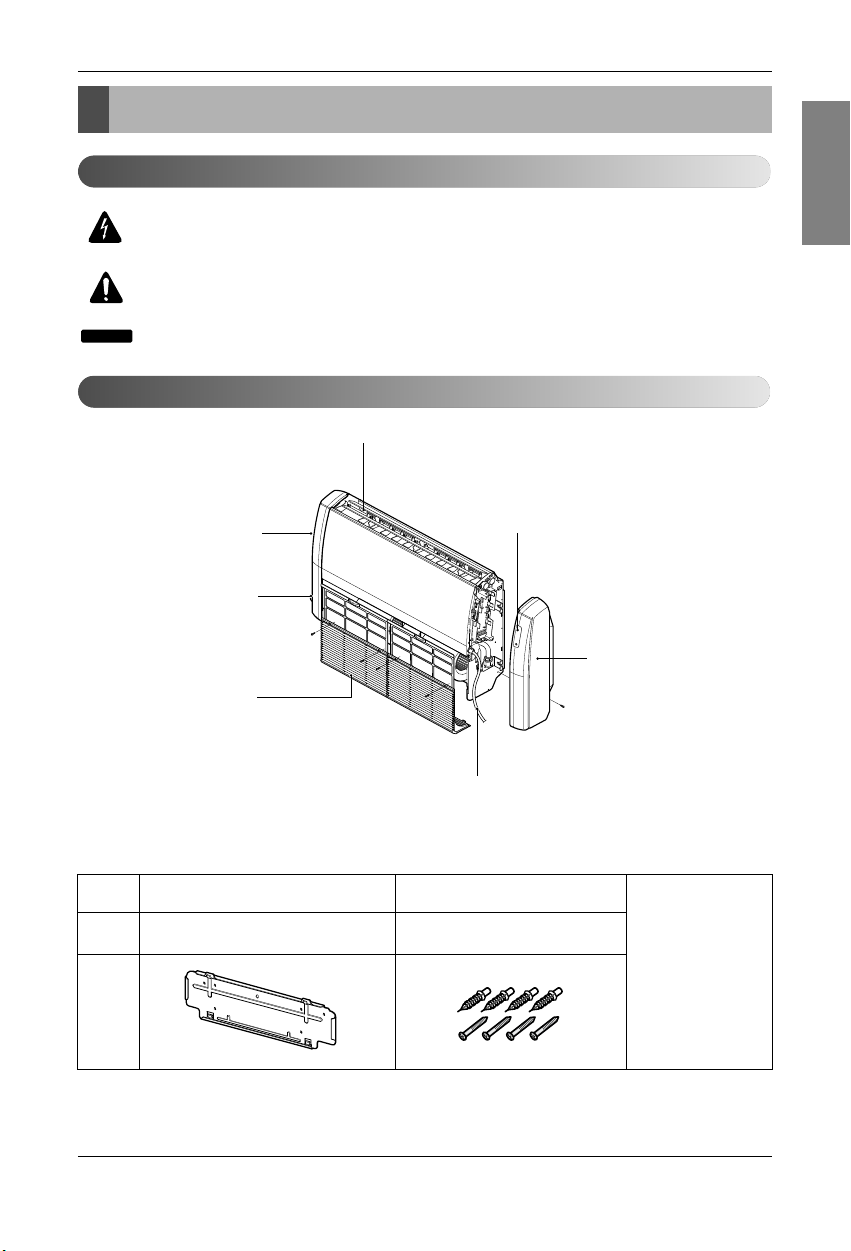
Features
Signal Receptor
Drain hose
Air Filter
Air Discharge
Right Side Cover
Inlet Grill
Left Side Cover
Standard Accessories
Name
Quantity
Shape
Installation plate
Type "A" screw and
plastic anchor
4EA1EA
(Other)
• Owner's manual
•
Installation manual
4 Indoor Unit
Safety Precautions
Safety Precautions
To prevent injury to the user or other people and property damage, the following instructions must be followed.
n Be sure to read before installing the air conditioner.
n Be sure to observe the cautions specified here as they include important items related to safety.
n Incorrect operation due to ignoring instruction will cause harm or damage. The seriousness is classified by the
following indications.
n Meanings of symbols used in this manual are as shown below.
This symbol indicates the possibility of death or serious injury.
This symbol indicates the possibility of injury or damage to properties only.
Be sure not to do.
Be sure to follow the instruction.
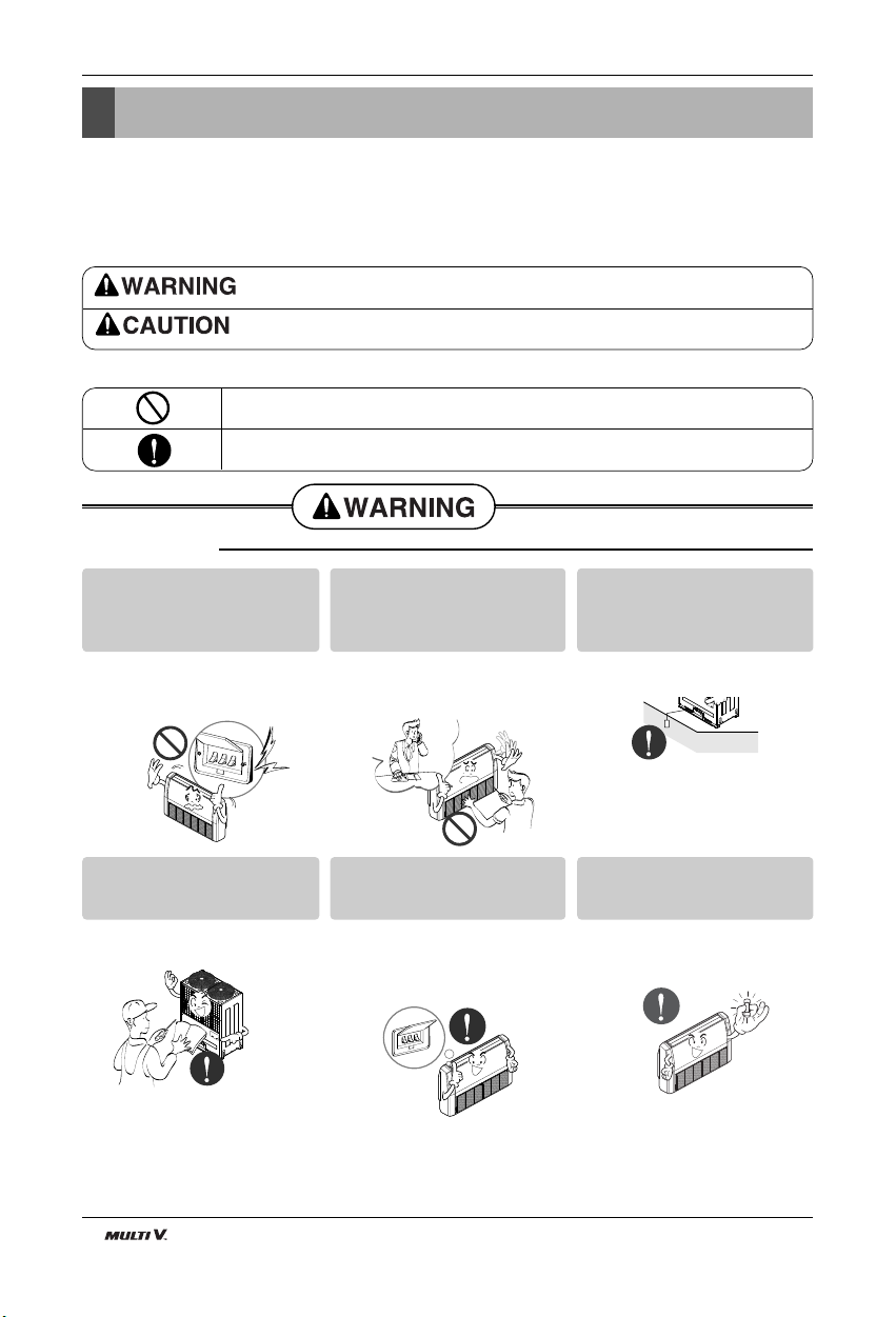
n Installation
Do not use a defective or underrated circuit breaker. Use this
appliance on a dedicated circuit.
• There is risk of fire or electric shock.
For electrical work, contact the
dealer, seller, a qualified electrician, or an Authorized Service
Center.
• Do not disassemble or repair the
product. There is risk of fire or electric shock.
Always ground the product.
• There is risk of fire or electric shock.
Install the panel and the cover
of control box securely.
• There is risk of fire or electric shock.
Always install a dedicated circuit and breaker.
• Improper wiring or installation may
cause fire or electric shock.
Use the correctly rated breaker
or fuse.
• There is risk of fire or electric shock.
Installation Manual 5
Safety Precautions
ENGLISH
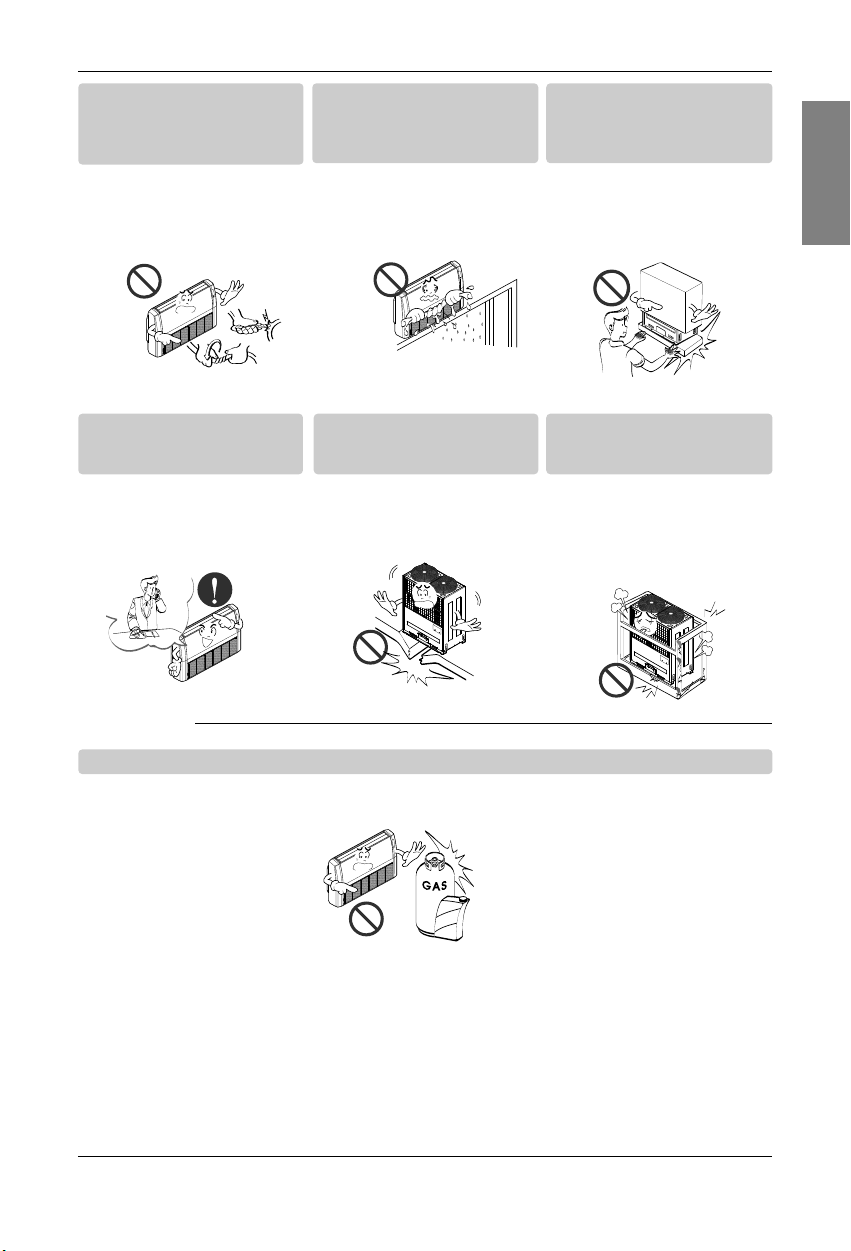
n Operation
Do not modify or extend the
power cable.
• There is risk of fire or electric shock.
Do not let the air conditioner
run for a long time when the
humidity is very high and a door
or a window is left open.
• Moisture may condense and wet or
damage furniture.
Be cautious when unpacking
and installing the product.
• Sharp edges could cause injury. Be
especially careful of the case edges
and the fins on the condenser and
evaporator.
For installation, always contact
the dealer or an Authorized
Service Center.
• There is risk of fire, electric shock,
explosion, or injury.
Do not install the product on a
defective installation stand.
• It may cause injury, accident, or
damage to the product.
Be sure the installation area
does not deteriorate with age.
• If the base collapses, the air conditioner could fall with it, causing property damage, product failure, and
personal injury.
Do not store or use flammable gas or combustibles near the product.
• There is risk of fire or failure of product.
Gasolin
6 Indoor Unit
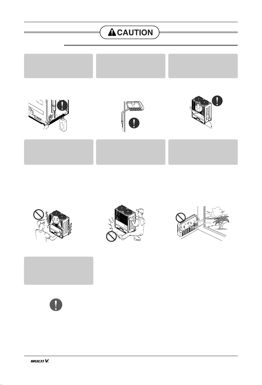
Safety Precautions
Always check for gas (refrigerant) leakage after installation or
repair of product.
• Low refrigerant levels may cause
failure of product.
Install the drain hose to ensure
that water is drained away properly.
• A bad connection may cause water
leakage.
Keep level even when installing
the product.
• To avoid vibration or water leakage.
Do not install the product where
the noise or hot air from the outdoor unit could damage the
neighborhoods.
• It may cause a problem for your
neighbors.
Use two or more people to lift
and transport the product.
• Avoid personal injury.
Do not install the product where
it will be exposed to sea wind
(salt spray) directly.
• It may cause corrosion on the product.
Corrosion, particularly on the condenser and evaporator fins, could
cause product malfunction or inefficient
operation.
n Installation
If you eat the liquid from the
batteries, brush your teeth and
see doctor. Do not use the
remote if the batteries have
leaked.
• The chemicals in batteries could
cause burns or other health
hazards.
90˚
Installation Manual 7
Installation
ENGLISH
Read completely, then follow step by step.
Installation
Indoor unit
1. Do not have any heat or steam near the unit.
2. Select a place where there are no obstacles in
front of the unit.
3. Make sure that condensation drainage can be
conveniently routed away.
4. Do not install near a doorway.
5. Ensure that the interval between a wall and the
left (or right) of the unit is more than 70cm.
6. Use a stud finder to locate studs to prevent
unnecessary damage to the wall.
More than"
700mm
More than"
300mm
More than"
700mm
Select the best Location
Preparing Work for Installation
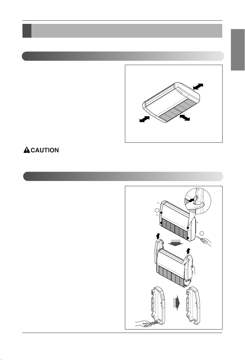
Open side cover
1. Remove two screws from side-cover as shown
in fig.
2. Unlock side-cover from side panel by slightly
pulling the edge of side cover.
3. Tap the side-cover with your palm on the backside.(Inlet grill side.)
4. Hold the side-cover with other hand while tapping to prevent it to fall down.
5. The Drain hole is on the left side of the unit and
side cover opening is common for drain pipe,
connecting pipe and wiring diagram.
6. Remove the rubber stopple in the desired drain
direction.
7. Knock out the pipe hole from the left side-cover
with the help or nipper/plier.
8. Knock hole on right side-cover only if right side
is selected for water drain.
2
1
Edge part
: In case that the unit is installed near the sea, the installation parts may be
corroded by salt. The installation parts (and the unit) should be taken appropriate anti-corrosion
measures.
8 Indoor Unit
Installation
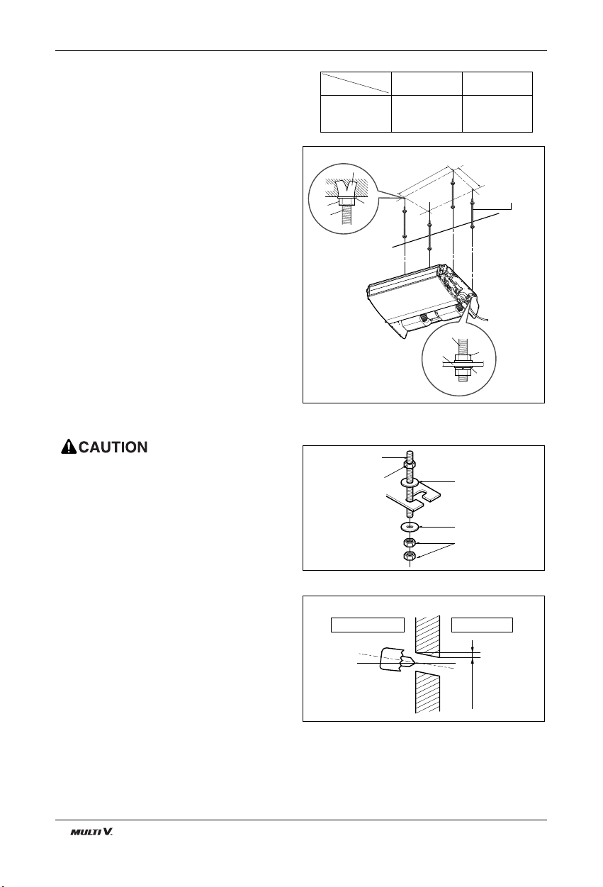
MOUNTING THE ANCHOR NUT AND
BOLT
• Prepare 4 suspension bolts. (Each bolts length
should be same.)
• Measure and mark the position for the
Suspension bolts and the piping hole.
• Drill the hole for anchor nut on the ceiling.
• Insert the nuts and washer onto the suspension
bolts for locking the suspension bolts on the ceiling.
• Mount the suspension bolts to the anchor-nuts
firmly.
• Secure the hangers onto the Suspension bolts
(adjust level roughly.) using nuts, washers and
spring washers.
• Adjust a level with a level gauge on the direction
of left-right, back-forth by adjusting suspension
bolts.
• Adjust a level on the direction of top-bottom by
adjusting supension bolts. Then the unit will be
declined to the bottomside so as to drain well.
5-7mm
(3/16"~5/16")
Indoor
WALL
Outdoor
Suspension bolt
B
A
Washer
Nut
Suspension
bolts
Ceiling
Anchor nut
Suspension
bolts
Max.
12mm
Hangen
Washer
Nut
Flat washer for M10
(accessory)
Flat washer for M10
(accessory)
Hanging bolt
(W3/8 or M10)
Nut
(W3/8 or M10)
Nut
(W3/8 or M10)
: Tighten the nut and bolt to prevent unit falling.
DRILL A HOLE IN THE WALL.
• Drill the piping hole with a ø70mm hole core drill.
Drill the piping hole at either the right or the left
with the hole slightly slanted to the outdoor side.
18/24k 855 320
DIM.
Capacity(Btu/h)
AB
 Loading...