

Page 1

INSTALLATION MANUAL
AIR
CONDITIONER
ENGLISH FRANÇAIS
ESPAÑOL
Please read this installation manual completely before installing the product.
Installation work must be performed in accordance with the national wiring
standards by authorized personnel only.
Please retain this installation manual for future reference after reading it
thoroughly.
Vertical Air Handling Unit
http://www.lghvac.com
www.lg.com
P/NO : MFL65003102
Copyright © 2010 - 2018 LG Electronics Inc. All Rights Reserved.
Page 2
IMPORTANT!
Please read this instruction sheet completely before installing the product.
This air conditioning system meets strict safety and operating standards. As the installer or service person,
it is an important part of your job to install or service the system so it operates safely and efficiently.
WARNING
• Installation or repairs made by unqualified persons can result in hazards to you and others.
Installation of all field wiring and components MUST conform with local building codes or, in the absence of local
codes, with the National Electrical Code 70 and the National Building Construction and Safety Code or Canadian
Electrical code and National Building Code of Canada.
• The information contained in the manual is intended for use by a qualified service technician familiar with safety
procedures and equipped with the proper tools and test instruments.
• Failure to carefully read and follow all instructions in this manual can result in equipment malfunction, property
damage, personal injury and/or death.
CAUTION
Safety Precautions
NOTE TO INSTALLING DEALER: The Owners Instructions and Warranty are to be given to the owner
:
Improper installation, adjustment, alteration, service or maintenance can void the warranty.
The weight of the condensing unit requires caution and proper handling procedures when lifting
or moving to avoid personal injury. Use care to avoid contact with sharp or pointed edges.
• Always wear safety eye wear and work gloves when installing equipment.
• Never assume electrical power is disconnected. Check with meter and equipment.
• Keep hands out of fan areas when power is connected to equipment.
• R-410A causes frostbite burns.
• R-410A is toxic when burned.
or prominently displayed near the indoor Furnace/Air Handler Unit.
Special warnings
When wiring:
Electrical shock can cause severe personal injury or death. Only a qualified,
experienced electrician should attempt to wire this system.
• Do not supply power to the unit until all wiring and tubing are completed or reconnected and checked.
• Highly dangerous electrical voltages are used in this system. Carefully refer to the wiring diagram and these
instructions when wiring. Improper connections and inadequate grounding can cause accidental injury or death.
• Ground the unit following local electrical codes.
Connect all wiring tightly. Loose wiring may cause overheating at connection points and a possible fire hazard.
•
•
The choice of materials and installations must comply with the applicable local/national or international standards.
When transporting:
Be careful when picking up and moving the indoor and outdoor units. Get a partner to help, and
bend your knees when lifting to reduce strain on your back. Sharp edges or thin aluminum fins on
the air conditioner can cut your finger.
When installing...
... in a wall: Make sure the wall is strong enough to hold the unit's weight.
... in a room: Properly insulate any tubing run inside a room to prevent "sweating" that can cause
... in moist or uneven locatinons: Use a raised concrete pad or concrete blocks provide a solid,
... in an area with high winds: Securely anchor the outdoor unit down with bolts and a metal
... in a snowy area(for Heat Pump Model): Install the outdoor unit on a raised platform that is
When connecting refrigerant tubing
• Keep all tubing runs as short as possible.
• Use the flare method for connecting tubing.
• Check carefully for leaks before starting the test run.
When servicing
• Turn the power OFF at the main power box(mains) before opening the unit to check or repair
electrical parts and wiring.
• Keep your fingers and clothing away from any moving parts.
• Clean up the site after you finish, remembering to check that no metal scraps or bits of wiring have
been left inside the unit being serviced.
It may be necessary to construct a strong wood or metal frame to provide added support.
dripping and water damage to wall and floors.
level foundation for the outdoor unit. This prevents water damage and abnormal vibration.
frame. Provide a suitable air baffle.
higher than drifting snow. Provide snow vents.
2 Vertical Air Handling Unit
Page 3

Vertical Air Handling Unit Installation Manual
TABLE OF CONTENTS
ENGLISH
Installation Requirements
Features.....................................4
Accessories ..............................4
Duct Connection Dimensions ...5
Safety Precautions ...................6
Installation.................................8
Selection of the best location....8
Upflow Installation ....................9
Duct work................................10
Horizontal-left Installation .......11
Connecting Pipes to the Indoor
Unit .........................................12
Preparation of Piping..............12
Plumbing materials and storage
methods..................................14
Insulation ................................16
Condensate Drain...................17
Wiring Connection ..................19
Electric Heater........................22
Dip Switch Setting of Indoor unit
PCB ........................................23
Group Control Setting.............24
Product Data ...........................28
External Static Pressure & Air
Flow........................................28
Minimum airflow by heater
capacity ..................................29
Electric Heater Static pressure
drop factors.............................29
Air Filter (Field supply) Static
pressure drop factors..............30
Required Parts Required Tools
o Level gauge
o Screw driver
o Electric drill
o Four type "A" screws
o Pipes: Gas side
Liquid side (Refer to
Product Data)
o Insulation materials
o Additional drain pipe
o Hole core drill
o Hexagonal wrench
o Gas-leak detector
o Vacuum pump
o Gauge manifold
o Owner's manual
o Thermometer
o Electric Heater installation
manual
Installation Manual 3
Page 4
Feature
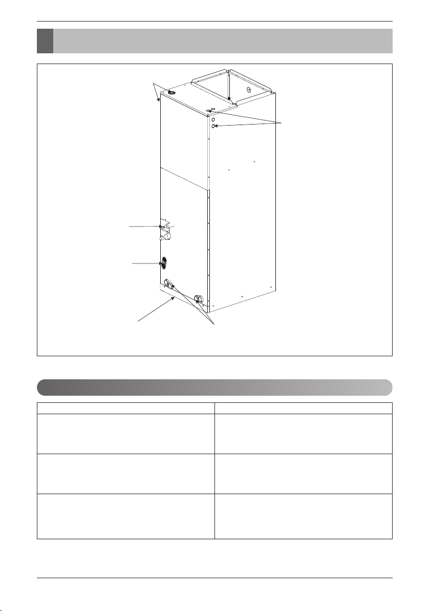
Features
Wiring knockouts
for conduit
Wiring knockouts
for conduit
Refrigerant
connections
Drain connections
for horizontal
application
Filter access
Accessories
Accessory Model Name
Wired remote controller
Wireless remote controller
Electric heater
4 Vertical Air Handling Unit
Drain connections for
upflow application
PQRCVSL0 (Black Color)
PQRCVSL0QW (White Color)
PQWRCDF0 (Cooling only)
PQWRHDF0 (Heat pump)
ANEH053B1
ANEH103B2
ANEH153B2
ANEH203B2
Page 5
Feature
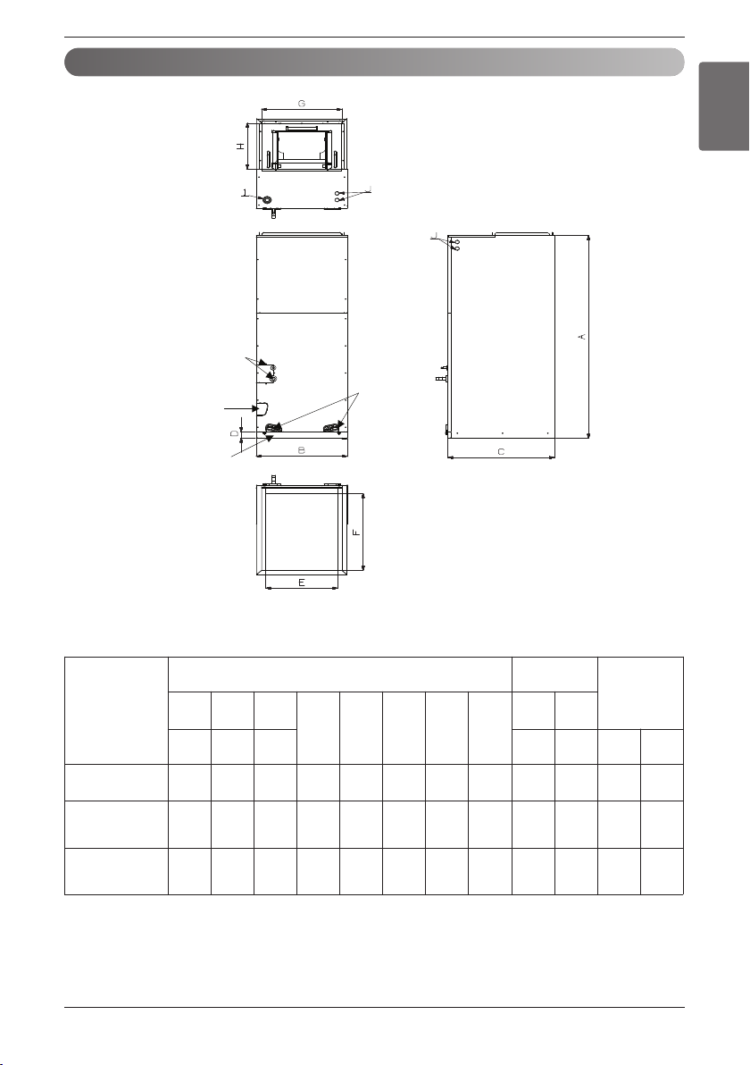
Duct Connection Dimensions
<Top>
Refrigerant
connections
Drain connections
for horizontal
application
Air filter cover
<Front>
Drain
connections
for upflow
application
ENGLISH
<Side-right>
Capacity
(kBtu/h (RT))
12(1.0)
18(1.5)
24(2.0)
30(2.5)
36(3.0)
42(3.5)
48(4.0)
54(4.5)
<Bottom>
Dimensions
A B C
Knock out
I J
D E F G H
Height Width Depth Power
48-5/8
(1236)18(457)
48-5/8
(1236)18(457)
55-1/8
(1401)25(635)
21-3/8
(540)
21-3/8
(540)
21-3/8
(540)
1-9/16
17-1/2
(40)
(445)20(530)17(432)
1-9/16
17-1/2
(40)
(445)20(530)17(432)
1-9/16
24-1/2
(40)
(623)20(530)24(610)
12-1/8
(308)
12-1/8
(308)
12-1/8
(308)
1-11/16
(43)
1-11/16
(43)
1-11/16
(43)
(Unit: inch(mm))
Wiring
Commu
nication
7/8
(22)
7/8
(22)
7/8
(22)
Refrigerant
Connections
Pipe size
Liquid Gas
1/4
1/2
(6.35)
(12.7)
3/8
5/8
(9.52)
(15.88)
3/8
5/8
(9.52)
(15.88)
Installation Manual 5
Page 6
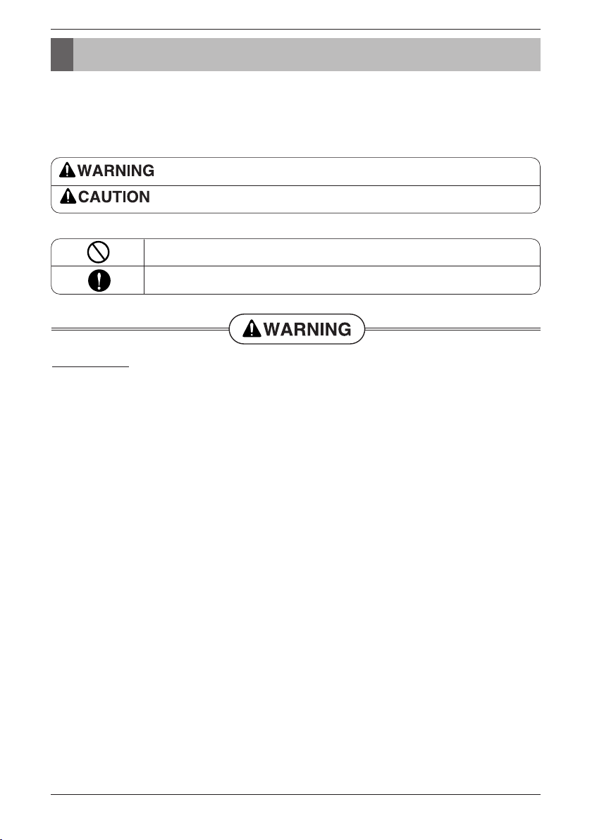
Safety Precautions
Safety Precautions
To prevent injury to the user or other people and property damage, the following instructions must be followed.
n Be sure to read before installing the air conditioner.
n Be sure to observe the cautions specified here as they include important items related to safety.
n Incorrect operation due to ignoring instruction will cause harm or damage. The seriousness is classified by the
following indications.
This symbol indicates the possibility of death or serious injury.
This symbol indicates the possibility of injury or damage to properties only.
n Meanings of symbols used in this manual are as shown below.
Be sure not to do.
Be sure to follow the instruction.
Installation
• Do not use a defective or underrated circuit breaker. Use this appliance on a dedicated circuit.
- There is risk of fire or electric shock.
• For electrical work, contact the dealer, seller, a qualified electrician, or an Authorized Service
Center.
- Do not disassemble or repair the product. There is risk of fire or electric shock.
• Always ground the product.
- There is risk of fire or electric shock.
• Install the panel and the cover of control box securely.
- There is risk of fire or electric shock.
• Always install a dedicated circuit and breaker.
- Improper wiring or installation may cause fire or electric shock.
• Use the correctly rated breaker or fuse.
- There is risk of fire or electric shock.
• Do not modify or extend the power cable.
- There is risk of fire or electric shock.
• Do not let the air conditioner run for a long time when the humidity is very high and a door or a window is left open.
- Moisture may condense and wet or damage furniture.
• Be cautious when unpacking and installing the product.
- Sharp edges could cause injury. Be especially careful of the case edges and the fins on the con-
denser and evaporator.
• For installation, always contact the dealer or an Authorized Service Center.
- There is risk of fire, electric shock, explosion, or injury.
• Do not install the product on a defective installation stand.
- It may cause injury, accident, or damage to the product.
• Be sure the installation area does not deteriorate with age.
- If the base collapses, the air conditioner could fall with it, causing property damage, product failure,
and personal injury.
6 Vertical Air Handling Unit
Page 7
Safety Precautions
• Use a vacuum pump or Inert (nitrogen) gas when doing leakage test or air purge. Do not compress
air or Oxygen and do not use Flammable gases. Otherwise, it may cause fire or explosion.
- There is the risk of death, injury, fire or explosion.
Operation
• Do not store or use flammable gas or combustibles near the product.
- There is risk of fire or failure of product.
Installation
• Always check for gas (refrigerant) leakage after installation or repair of product.
- Low refrigerant levels may cause failure of product.
• Install the drain hose to ensure that water is drained away properly.
- A bad connection may cause water leakage.
• Keep level even when installing the product.
- To avoid vibration or water leakage.
• Do not install the product where the noise or hot air from the outdoor unit could damage the neighborhoods.
- It may cause a problem for your neighbors.
• Use two or more people to lift and transport the product.
- Avoid personal injury.
• Do not install the product where it will be exposed to sea wind (salt spray) directly.
- It may cause corrosion on the product. Corrosion, particularly on the condenser and evaporator
fins, could cause product malfunction or inefficient operation.
• If you eat the liquid from the batteries, brush your teeth and see doctor. Do not use the remote if the
batteries have leaked.
- The chemicals in batteries could cause burns or other health hazards.
• Safely dispose of the packing materials.
- Packing materials, such as nails and other metal or wooden parts, may cause stabs or other
injuries.
- Tear apart and throw away plastic packaging bags so that children may not play with them. If chil-
dren play with a plastic bag which was not torn apart, they face the risk of suffocation.
ENGLISH
Installation Manual 7
Page 8
Installation
Installation
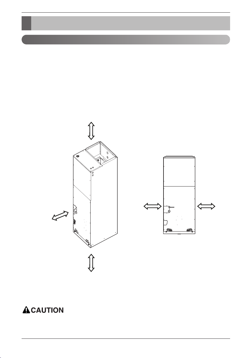
Selection of the best location
• Where optimum air distribution can be ensured.
• Where nothing blocks air passage and install the duct work.
• Where condensate can be properly drained.
• Where the ceiling is strong enough to bear the indoor unit weight.
• Where the false ceiling is not noticeably on an incline.
• Where sufficient clearance for maintenance and service can be ensured.
• Where piping between indoor and outdoor units is possible within the allowable limit. Refer to the
installation manual for the outdoor unit.
• Vertical Air Handling Unit can be installed for upflow and horizontal-left positions.
More than
350(13-25/32)
More than
600(23-5/8)
clearance from
access panels
for Service
More than
350(11-25/32)
NOTE : The primary and secondary drain line must be trapped to allow proper drainage of condensate
water, If the secondary drain line is not used, it must be capped.
In the case of sea coast installation, salt residue may cause corrosion of cabinet and component
parts. Please take appropriate anti-corrosion measures.
8 Vertical Air Handling Unit
More than
250(9-27/32)
More than
250(9-27/32)
Unit: mm (inch)
Page 9
Installation
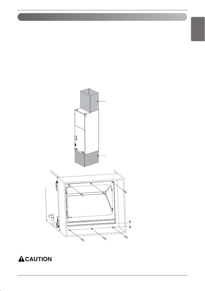
Upflow Installation
• Position unit for plenum installation.
• The plenum should be secured in order to support the installation of adapter callers accommodate the
installation of any duct work.
• Seal all duct work according to local codes to prevent air leakage. Ensure that filter access is unobstructed.
• The air handler support platform should be sturdy enough to support the cabinet plus any accessory
components including filter box.
• The minimum height clearance is 14inches(350mm) to maintain proper air flow.
• Vibration isolators (purchased locally) must be placed between the unit and the pedestal.
• An illustration showing an example of where a vibration isolator should be added would clarify what
the installing contractor should do to properly position the isolator.
Field Supplied
Supply Duct
Field
Supplied Return
Plenum
ENGLISH
More than
1inch (25mm)
More than 6 screws (M4*25L)
Do not connect the screws on Front and Rear side, it may cause the filter can not be mounted.
Installation Manual 9
Page 10
Installation
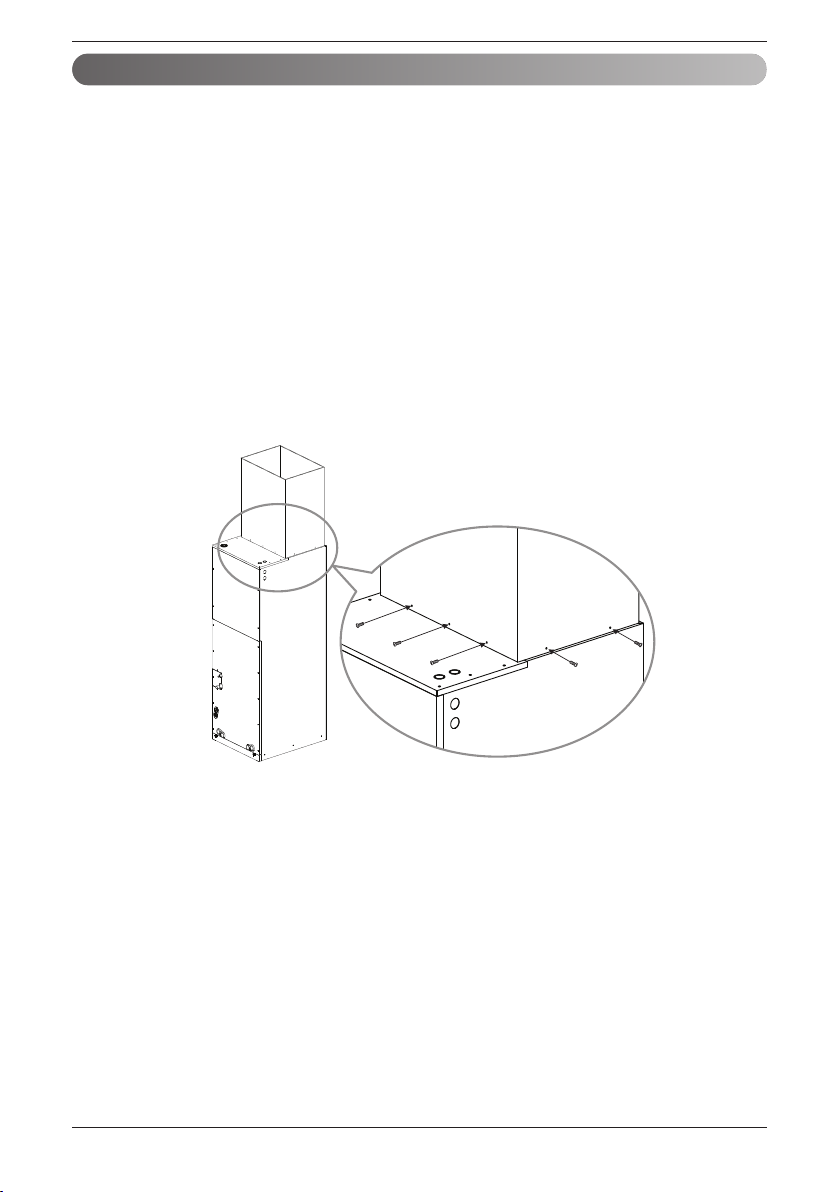
Duct work
• Over 10 screws should be used for joining supply duct with the unit.
• To prevent vibration transmission, exploit flexible connectors between duct and the unit. It is mandatory that the flexible connector between unit and duct at discharge connection should be made off heat
resistive material when electric heater is installed.
• Duct work must be insulated and covered with vapor barrier when routed through unconditioned
space.
• Internal acoustical insulation lining may necessary for the metal duct system if it do not have 90°
elbow and 10ft. of main duct to first branch takeoff.
• It is advised that a fibrous duct work could be used as a substitute if built and installed in accordance
with the most recent edition of SMACNA construction standard on fibrous glass ducts.
• Collectively fibrous duct work and acoustical lining shall obey National Fire Protection Association
standards 90A or B as tested by UL standard 181 for class 1 air ducts.
• Seal around the delivery duct subsequent to when the duct is secured so that to facilitate prevention
of air leakage.
10 Vertical Air Handling Unit
More than 10 screws
(M4*25L)
Page 11

Installation
Horizontal-left Installation
ENGLISH
• It is particular that the units should not be installed in such a manner that the access panels facing up
or down
• It should be confirmed that the installation is in accordance with all relevant building codes that may
necessitate installation of external condensate pan.
-Set up a support for unit by locating it in or above external condensate pan.
• Angle steel support brackets with threaded rods which supporting the units from the underside should
be used as shown in the figure below if the units are suspended.
• If not suspended then also it should be supported as same as mentioned above and also carefully
isolated to avoid sound transmission. The size of the support should comparatively bigger than the
unit and the unit must be place at centre of the support.
• Locally available vibration isolators must be placed between the unit and the support.
• The same installation method of up flow type has to be used in the case of Return Plenum and supply duct.
Field Supplied
Supply Duct
More than 3/8 inch
(9.5mm) threaded rod
Field Supplied
Return Plenum
More than 1-1/2
inch(38 mm) X 1-1/2
inch(38 mm) angle
Recommended
length more than 26
B
C
A
inch(660 mm) with
2 inch(50 mm)
clearance on both
sides of unit
Suspension support locations
Caapcity
(kBtu(RT))
12(1.0)
18(1.5)
24(2.0)
30(2.5)
36(3.0)
42(3.5)
48(4.0)
54(4.5)
ABC
4(100) 23(580)
4(100) 29(730) 48(1220)
(Unit : inch(mm))
Dimension
41-1/2
(1050)
To ensure proper drainage for horizontal installations, unit must be installed so it is within 1/8” level of
the length and width of unit.
Installation Manual 11
Page 12

Installation
Copper
pipe
90°
Slanted Uneven Rough
Pipe
Reamer
Point down
Cut the edge
Liquid pipe
Gas pipe
Upper front panel
Air filter cover
Top screw
Bottom screw
Lower front
panel
Refrigerant
pipe cover
Preparation of Piping
Cut the pipes
1. Use the pipes purchased locally.
2. Measure the distance between the indoor and the outdoor unit.
3. Cut the pipes a little longer than measured distance.
Burrs removal
1. Completely remove all burrs from the cut cross section of pipe/tube.
2. While removing burrs put the end of the copper tube/pipe in a downward direction while removing
burrs location is also changed in order to avoid dropping burrs into the tubing.
1. First detach the upper front panel followed by air
12 Vertical Air Handling Unit
Connecting Pipes to the Indoor Unit
filter cover from the body.
2. Detach the lower front panel and refrigerant pipe
cover from the body.
Note: While detaching the lower front panel,
remember to remove the top and bottom screws.
Page 13

Installation
Cut the edge
Liquid pipe
Gas pipe
Cutting the Pipe for Cutting the Pipe for
3/8inch (9.52mm).3/8inch (9.52mm).
Cutting Position is less Cutting Position is less
than 0.4inch (10mm).than 0.4inch (10mm).
Cutting the Pipe for
3/8inch (9.52mm).
Cutting Position is less
than 0.4inch (10mm).
Cutting the Pipe for
3/8inch (9.52mm).
Cutting Position is less
than 0.4inch (10mm).
Liquid pipe
Liquid pipe
Gas pipeGas pipe
Liquid pipe
Brazing for
Brazing for
1/4inch(6.35mm) 1/4inch(6.35mm)
Brazing for
1/4inch(6.35mm)
Brazing for
1/4inch(6.35mm)
Gas pipe
Cap
CapCap
Brazing
Brazing Brazing
Cut the edge
Liquid pipe
Gas pipe
Cut the edgeCut the edge
Liquid pipeLiquid pipe
Gas pipeGas pipe
Cut the edge
Liquid pipe
Gas pipe
Lower
front
panel
Upper
front
panel
Refrigerant
pipe cover
Cut the edge
Gas pipe
ENGLISH
3. Cut the refrigerant pipe (Liquid Pipe edge)
and make sure the factory charged refrigerant is emerging out. (This confirms there is
no leakage.)
4. Detach Liquid and Gas Pipe
- Gas Pipe: Remove the Cap by Brazing
Liquid Pipe: There are 2 kinds of Liquid Pipe.
-
Liquid Pipe Detach Pipe
1/4 (6.35) Brazing
3/8 (9.52) Cutting
- If you do not use proper cutter size
when cutting liquid pipe, it would make
damage to the gas pipe.
5. Connect the field piping by brazing.
6. Attach the two panels to the body.
- Wrap the gas and liquid pipe with wet towel.
(If not wrapped with a wet towel, there may
be damages drain pan or pipe insulations.)
Note: Overlap the connection pipe insulation material and the indoor unit pipe insulation material. Bind
Completely remove the refrigerant and then do brazing. Otherwise, high pressure is a risk
of injury due to explosions
them together with vinyl tape so that there may be no gap.
Installation Manual 13
Page 14

Installation
Moisture
Dust
Leakage
Always blow nitrogen into pipe which is brazed. Always use a non-oxidizing brazing material for brazing the parts and do not use flux. If not, oxidized film can cause clogging or damage to the compressor unit and flux can harm the copper piping or refrigerant oil.
6
1
2
45
3
1 Refrigerant piping 4 Taping
2 Pipe to be brazed 5 Valve
3 Nitrogen 6 Pressure-reducing valve
Note : The torch tip should be positioned at the opposite angle to shop the
correct way to apply heat on the pipe coupling.
Plumbing materials and storage methods
Pipe must be able to obtain the specified thickness and should be used with low
impurities.
Also when handling storage, pipe must be careful to prevent a fracture, deformity
and wound.
Should not be mixed with contaminations such as dust, moisture.
Refrigerant piping on three principles
Drying Cleanliness Airtight
Should be no moisture
inside
Items
- Significant hydrolysis of refrigerant oil
Cause failure
Countermeas
14 Vertical Air Handling Unit
- Degradation of refrigerant oil
- Poor insulation of the compressor
- Do not cold and warm
- Clogging of EEV, Capillary
- No moisture in the pipe
- Until the connection is completed, the
plumbing pipe entrance should be
strictly controlled.
- Stop plumbing at rainy day.
- Pipe entrance should be taken side or
ure
bottom.
- When removal burr after cutting pipe,
pipe entrance should be taken down.
- Pipe entrance should be fitted cap
when pass through the walls.
- Degradation of refrigerant oil
- Poor insulation of the compressor
- Do not cold and warm
- Clogging of EEV, Capillary
- No dust in the pipe.
- Until the connection is completed, the
plumbing pipe entrance should be
strictly controlled.
- Pipe entrance should be taken side or
bottom.
- When removal burr after cutting pipe,
pipe entrance should be taken down.
- Pipe entrance should be fitted cap
when pass through the walls.
No dust inside.
There is no refrigerant
leakage
- Gas shortages
- Degradation of refrigerant oil
- Poor insulation of the compressor
- Do not cold and warm
- Airtightness test should be.
- Brazing operations to comply with standards.
- Flare to comply with standards.
- Flange connections to comply with
standards.
Page 15

Installation
Nitrogen substitution method
Welding, as when heating without nitrogen substitution a large amount of the oxide film is formed on the internal piping.
The oxide film is a caused by clogging EEV, Capillary, oil hole of accumulator and suction hole of oil pump in compressor.
It prevents normal operation of the compressor.
In order to avoid this problem, Welding should be done after replacing air by nitrogen gas.
When welding plumbing pipe, the work is required.
◆How to work
Regulator
ENGLISH
Welding Point
Oxide scale
Note) should not block the outlet side.
When the internal pressure in pipe is above the
atmospheric pressure, pinhole is occurred and it
is a leakage cause.
1. Always use the nitrogen.(not use oxygen, carbon dioxide, and a Chevron gas):
Please use the following nitrogen pressure 0.02MPa
Oxygen --------- Promotes oxidative degradation of refrigerant oil.
Because it is flammable, it is strictly prohibited to use
Carbon dioxide --- Degrade the drying characteristics of gas
Chevron Gas ---- Toxic gas occurs when exposed to direct flame.
2. Always use a pressure reducing valve.
3. Please do not use commercially available antioxidant.
The residual material seems to be the oxide scale is observed.
In fact, due to the organic acids generated by oxidation of the alcohol contained in the anti-oxidants, ants nest corrosion
occurs. (causes of organic acid → alcohol + copper + water + temperature)
Nitrogen gas
Pressure 0.02MPa less
Taping
(Should not
contain air)
Auxiliary valve
Nitrogen
Installation Manual 15
Page 16

Installation
Union for liquid pipe
Refrigerant pipe
and thermal
insulator
(Local supply)
Union for gas pipe
Thermal insulator for
refrigerant pipe(Local supply)
Hose crip for thermal insulator
(Local supply)
Make sure that there is no clearance here.
Overlap with thermal
insulator for piping.
Thermal insulator for refrigerant pipe
(Field supply)
Thermal insulator for
Piping (Field supply)
Hose crip for thermal insulator (Field supply)
Insulation
Insulate the joint and tubes completely.
Thermal insullaton : All thermal insulation must comply with local requirement.
Recommend
Classification
Liquid Pipe
Gas Pipe
16 Vertical Air Handling Unit
Ø1/4(6.35)
Ø3/8(9.52)
Above Ø1/2
(12.7)
Ø3/8(9.52)
Ø1/2 (12.7)
Ø5/8(15.88)
Ø3/4(19.05)
Ø7/8(22.22)
Ø1(25.4)
Ø1-1/8(28.58)
Ø1-1/4(31.75)
Ø1-3/8(34.9)
Ø1-1/2(38.1)
Ø44.45(1-3/4)
Air conditioned location Non-air conditioned location
Note1)
General
location
Above t 3/8
(9.52)
Above t 1/2
(12.7)
Above t 1/2
(12.7)
Note2)
Special
location
Above t 3/8
(9.52)
Above t 1/2
(12.7)
Above t 3/4
(19.05)
Note3)
General
location
Above t 3/8
(9.52)
Above t 1/2
(12.7)
Above t 3/4
(19.05)
Note4)
condition
Above t 3/8
(9.52)
Above t 1/2
(12.7)
Above t 1 (25)
Above t 3/4
(19.05)
Above t 1 (25) Above t 1 (25)
Negative
Page 17

Installation
* Note 1) General location: When the pipe passes through indoors in which the indoor unit is operated
- Apartment, classroom, office, mall, hospital, office-tel etc.
Note 2) Special location
1. When the location is air conditioned but has severe temperature/humidity difference due to
high ceiling
- Church, auditorium, theater, lobby etc.
2. When the location is air conditioned but the internal temperature/humidity of the ceiling finishing is high
- Bathroom/swimming pool locker room etc. (Building with roof ceiling of sandwich assembly
type)
Note 3) General location: When the pipe passes indoors where the indoor unit is not operated
- Hall way etc. (Dormitory, school, office-tel)
Note 4) Negative condition: When below conditions 1 and 2 are met.
1. When the pipe passes indoors where the indoor unit is not operated
2. When the humidity is high, regionally, and there is no air flow in the pipe passing area
- When installing the outside unit within the outside pipe tray or at a location where it is ok to
have freezes, apply 13t.
- If you are not sure with the selection of heat insulation material, coordinate with the supervision or HQ.
- The thickness of the above heat insulation material is based on the heat conductivity of
0.088W/m°C.
ENGLISH
Condensate Drain
• The drainage performance has to be optimized by installing both primary and secondary drain lines
along with properly sized condensate traps in order to prevent property damage.
• Care should be taken to avoid the blocking of filter access panel while connecting condensate drain
lines. The primary and secondary condensate traps has to be primed after connecting to the drain
pan.
• A field supplied external condensate pan has to be installed underneath the entire unit if the unit is
above the living space . Other wise damage may result due to condensate over flow. Also a additional
external condensate line should run from unit in to the pan.
• The entire condensate should be drained from the external condensate pan to some noticeable
area. It is advised to install traps in condensate lines as near to the coil as possible. The outlet of
each trap should be below its connection to the condensate pan avert condensate from overflowing
drain pan.
• If located above the living area then all traps should be prime and insulated and also tested for leakage.
• PVC 3/4 inch(19.05mm) male pipe thread fitting is advised to use at condensate pan with gentle tight.
• For easy drain flow the drain hose has to be pointed downward.
• Care should be taken to not use pipe joint connection or PVC/CPVC for units drain line connection.
Use only Teflon tape.
• For preventing winter freeze up on condensate line special means should be provided for drainage.
Installation Manual 17
Page 18

Installation
Drainage hole
U-Trap
B
C
A ≥
2-9/16 inch
(70mm)
B ≥ 2C
C ≥ 2 x SP
SP = External Pressure
(in.wc)
Ex) External Pressure
= 0.4in.wc(10mmAq)
A ≥ 2-9/16 inch(70mm)
B ≥ 1-7/12 inch(40mm)
C ≥ 19/24 inch(20mm)
A
Make sure to be closed.
Unit
Drainage pipe
(Field supply)
Thermal insulator
(Field supply)
Applied U-Trap Dimension
CORRECT
• Install the U-Trap to prevent
a water leakage caused by the blocking
of intake air filter.
Upflow Drain Horizontal-left Drain
INCORRECT
3/4 inch(19.05mm)
connector
Horizontal-left
Drain Knockout
Air filter cover
Main drain along with suitable trap.
( Field supplied trap with sufficient
depth can be used. P-traps of standard
size are not sufficient. Refer the figure
for recommended condensate trap.)
Supplementary drain
with proper trap. (field
supplied kit can be used)
GRADIENT OF UNIT AND DRAIN PIPING
• Alway lay the drain with downward inclination(1/50 to 1/100).
Prevent any upward flow or reverse flow in any part.
• 5/24 inch(5mm) or thicker formed thermal insulator shall always be provided for the drain pipe.
The supplied flexible drain hose should not be strained.
A strained hose may cause leakage of water.
18 Vertical Air Handling Unit
Page 19

Installation
Wiring
knockouts
Control
Box Cover
Upper
Front Panel
Wiring Connection
Connect the wires to the terminals on the control board individually according to the outdoor unit
connection.
Ensure that the color of the wires of outdoor unit and the terminal No. are the same as those of
indoor unit respectively.
208/230V 1Φ 60Hz
Outdoor unit
Terminal Block Indoor
1(L1) 2(L2) 3(A) 4(B)
INDOOR POWER
INPUT
<208/230 1Φ 60Hz>
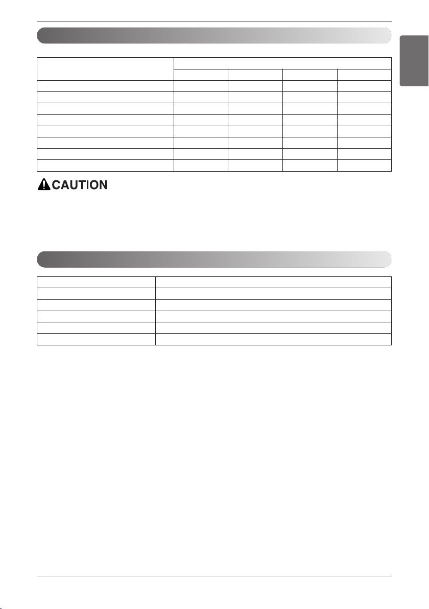
Min wire size
(AWG)
Power cable 22 1/2 (21.3) 7/8 (22.2)
Communication cable 22 1/2 (21.3) 7/8 (22.2)
* Copper wire should be used.
Indoor unit Central controller
SODU SODU
IDU IDU
DRY1 DRY2 GND INTERNET
Size of conduit
(inch(mm))
Outdoor
unit
12V
Unit : inch(mm)
Knockout diameter
(inch(mm))
ENGLISH
1. Detach the upper panel & control box cover.
And remove two wiring Knockouts.
Installation Manual 19
Page 20

Installation
power cable
communication cable
Lock nut
Conduit
mounting plate
1/2inch(21.3 mm)
Conduit
2. Install conduit to the wiring knockouts.
Connect power/communication cable to terminal block through the wiring knockouts.
NOTE :
1. Separately wire power supply cord and connecting cable.
2. Use heat-proof electrical wiring capable of withstanding temperature up to 75°C(167°F).
3. Use outdoor and waterproof connection cable NRTL(UL, ETL, CSA...) listed and rated more than
300V for the connection between indoor and outdoor unit. and this cable should be enclosed in
conduit.
After the confirmation of the above conditions, prepare the wiring as follows:
1) Never fail to have individual power specialized for the air conditioner. As for the method
of wiring, follow by the circuit diagram posted on the inside of control box cover.
2) Provide a circuit breaker switch between power source and the unit.
3) The screws which fasten the wiring in the casing of electrical fittings are liable to come
loose from vibrations to which the unit is subjected during the course of transportation.
Check them and make sure that they are all tightly fastened. (If they are loose, it could
give rise to burn-out of the wires.)
4) Specification of power source
5) Confirm that electrical capacity is sufficient.
6) Be sure that the starting voltage is within 10% plus or minus of nameplate voltage rating.
7) Confirm that the cable thickness is as specified in the power sources specification.
(Particularly note the relation between cable length and thickness.)
8) Never fail to equip GFCI breaker when installing the air handler near wet or moist locations.
9) The following troubles would be caused by voltage drop-down.
• Vibration of a magnetic switch, damage on the contact point, fuse breaking, disturbance by the
normal function of an overload protection device.
• Proper starting power is not given to the compressor.
HAND OVER
Teach the customer the operation and maintenance procedures, using the operation manual.
(air filter cleaning, temperature control, etc.)
NOTE : Openings where field wiring enters the cabinet must be completely sealed.
20 Vertical Air Handling Unit
Page 21
Installation
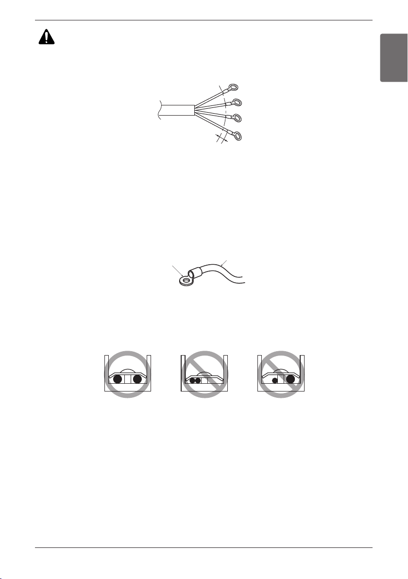
Round pressure terminal
Power wire(Ground wire)
CAUTION :
ENGLISH
The connecting cable connected to the indoor and outdoor unit should be complied with the following specifications (This equipment shall be provided with a cord set complying with the national regulation).
GN/
YL
20mm
(25/32 inch)
If the supply cord is damaged, it must be replaced by a special cord or assembly available from
the manufacturer of its service agent.
u Precautions when laying power and ground wiring
Use round pressure terminals for connections to the power terminal block.
When laying ground wiring, you must use round pressure terminals.
When none are available, follow the instructions below.
• Do not connect wiring of different thicknesses to the power terminal block. (Slack in the power wiring
may cause abnormal heat.)
• When connecting wiring which is the same thickness, do as shown in the figure below.
• For wiring, use the designated power wire and connect firmly, then secure to prevent outside pressure
being exerted on the terminal block.
• Use an appropriate screwdriver for tightening the terinal screws. A screwdriver with a small head will
strip the head and make proper tighterning impossible.
• Over-tightening the terminal screws may break them.
Installation Manual 21
Page 22

Installation
Electric Heater
Feature (Example: 5kW)
Bi metal
Bracket
Terminal Block
Relay
Heater Cable
Heater Coil
* Note: Image shown above may vary depends on model capacity.
Available heater in model
Capacity
(kBtu/h (RT))
12(1.0)
18(1.5)
24(2.0)
30(2.5)
36(3.0)
42(3.5)
48(4.0)
54(4.5)
5 101520
○
○
○○
○○
○○
○○○○
○○○○
○○○○
※ If you want to know more optional operation, please refer to the Electric Heater Manual.
※ Heater Model
5kW: ANEH053B1
10kW: ANEH103B2
15kW: ANEH153B2
20kW: ANEH203B2
Heater Capacity (kW)
Not available Not available Not available
Not available Not available Not available
Not available Not available
Not available Not available
Not available Not available
22 Vertical Air Handling Unit
Page 23

Installation
Dip Switch Setting of Indoor unit PCB
Function Description Setting Off Setting On Default
Communication
SW1
Cycle
SW2
Group Control
SW3
Dry Contact Mode
SW4
Installation
SW5
Heater linkage
SW6
Ventilator linkage
SW7
Vane selection
(Console)
Region selection
Etc.
SW8
1. In Multi V Models without Electric Heater
- Dip switch 1, 2, 6, 8 must be set OFF.
2. In the case of Multi V Models with Electric Heater, Dip switch 5,6 must be set ON.
- SW 5 ON: Fan operates continuously. (During defrosting or oil return operation, uninterrupted heating can be attained, as a result of continuous heater and fan operation.)
- SW5 OFF: Fan discontinuous operation (There would be reduction in heating capacity
while defrosting or oil return operation.)
- SW6 ON: Automatic Heater operation (Heater operates automatically according to the
heater logic without owner’s intervene.)
- SW6 OFF: Heater manual operation (Owner’s involvement is required for on/off operation.
But the heater operation would be as per the heater logic.)
N/A (Default)
N/A (Default)
Selection of Master or Slave
Selection of Dry Contact
Mode
Fan continuous operation
Selection of Heating Working
Selection of Ventilator linkage
Selection of up/down side
Vane
Selection tropical region
Spare
-
-
Master
Wired/Wireless remote
controller
Selection of Manual or Auto
operation Mode
Continuous operation Removall
-
Linkage Removal
Up side + Down side Vane
General model
-
Up side Vane
Tropical model
-
-
Slave
Auto
-
-
Working
Only
-
ENGLISH
Off
Off
Off
Off
Off
Off
Off
Off
Installation Manual 23
Page 24

Installation
Wired remote controller 1
Dip Switch in PCB (Cassette and Duct Type indoor units)
1. It is possible to 16 indoor units(Max) by one wired remote controller.
Set only one indoor unit to Master, set the others to Slave.
2. It is possible to connect with every type of indoor units.
3. It is possible to use wireless remote controller at the same time.
4. It is possible to connect with Dry Contact and Central controller at the same time.
GND
Signal
12 V
Master
Slave
Slave
Slave
Display Error Message
Only connect serial signal and GND lines
between slave indoor unit
LGAP Network System
- No. 3 Off - No. 3 On
- The Master indoor unit is possible to recognize Dry Contact and Central Controller only.
- In case of Central controller and Group controller at the same time, it is possible to connect
standard 2series indoor units or later since Feb. 2009.
- In case of Central controller setting, the Central controller can control indoor units after
setting only the address of master indoor unit.
- Slave indoor unit will be operated like master indoor unit.
- Slave indoor unit can not be individually controlled by Central controller.
- Some remote controller can’t perform with Dry Contact and Central controller at the same
time. So contact us further information about it.
Master
Group Control Setting
1. Group Control 1
24 Vertical Air Handling Unit
Page 25

It is possible to control N indoor units by wired remote controller M units. (M+N≤17 Units)
Set only one indoor unit to Master, set the others to Slave.
Set only one wired remote controller to Master, set the others to Slave.
Other than those, it is same with the Group Control 1.
Slave
Display Error Message
Donʼt connect serial 12V line
Master
(2) Group Control 2
Wired remote controllers
GND
Signal
12 V
Slave
Slave
Slave
Master
LGAP Network System
6. In case of Group Control, it is possible to use following functions.
- Selection of operation options (operation/stop/mode/set temperature)
- Control of flow rate (High/Middle/Low)
- It is not possible at some functions.
Master/Slave setting of indoor units be set possible using a PCB Dip Switch.
It is possible to connect indoor units since Feb. 2009.
In the other cases, please contact LGE.
It can be the cause of malfuctions when there is no setting of master and slave.
5. In case of any error occurs at indoor unit, display on the wired remote controller.
Exception of the error indoor unit, an individual indoor unit control possibility.
2. Group Control 2
Installation
ENGLISH
Installation Manual 25
Page 26

Installation
Display Error Message
Master
Slave
1. It is possible to connect two wired remote controllers with one indoor unit.
2. Every types of indoor unit is possible to connect two remote controller.
3. It is possible to use wireless remote controller at the same time.
4. It is possible to connect with Dry Contact and Central controller at the same time.
5. In case of any error occurs at indoor unit, display on the wired remote controller.
6. There isnʼt limits of indoor unit function.
❈ Maximum 2wired remote controllers can be connected with 1 indoor unit.
Wired remote controller 2 + Indoor unit 1
GND
Signal
12 V
Slave
Slave
Slave
Master
LGAP Network System
3. 2 Remote Control
26 Vertical Air Handling Unit
Page 27

Installation
Slave
Mas te r
Mas ter
PZCWRCG3
Mas ter Slav e
PZCWRC2
Indoor unit 2 EA +Wired remote controller
❈ PZCWRCG3 cable used for connection ❈ PZCWRC2 cable used for connection
Indoor unit 1 EA +Wired remote controller 2EA
It is possible to set group control by using below accessories.
4. Accessories for group control setting
Apply totally enclosed noncombustible conduit in case of local building code Requiring plenum
cable usage.
ENGLISH
Installation Manual 27
Page 28

Product Data
Product Data
External Static Pressure & Air Flow
Capacity
(kBtu/h(RT))
54(4.5)
48(4.0)
42(3.5)
36(3.0)
30(2.5)
24(2.0)
18(1.5)
12(1.0)
Flow rate
(CFM)
High(1475) 77 82 87 93 98
Middle(1400) 74 79 84 91 96
Low(1260) 67 75 80 87 90
High(1400) 74 79 84 91 96
Middle(1260) 67 75 80 87 90
Low(1000) 56 65 72 77 84
High(1250) 67 75 80 87 90
Middle(1100) 61 67 75 80 87
Low(1000) 56 65 72 77 84
High(990) 80 85 90 95 100
Middle(880) 65 72 80 85 92
Low(800) 65 69 77 82 90
High(880) 65 72 80 85 92
Middle(800) 62 69 77 82 90
Low(630) 53 65 70 75 85
High(710) 56 67 74 78 87
Middle(640) 53 65 70 75 85
Low(480) 53 55 64 70 79
High(580) 53 60 68 74 84
Middle(530) 53 58 66 72 82
Low(480) 53 55 64 70 79
High(530) 53 58 66 72 82 84 92 92 92 92
Middle(480) 53 56 64
Low(380) 53 54 62 69 77 83 92 92 92 92
0.1 0.2 0.3 0.4 0.5
Setting Value @ ESP(in.wc)
0.6 0.7 0.8 0.9 1.0
102 110 115 115 11 5
102 110 115 115 11 5
98 102 11 0 11 5 11 5
102 110 115 115 11 5
98 102 11 0 11 5 11 5
90 98 105 108 115
98 102 11 0 11 5 11 5
92 100 108 110 115
90 98 105 108 115
103 103 103 103 103
98 103 103 103 103
96 101 101 101 101
98 103 103 103 103
96 101 101 101 101
91 96 96 96 96
94 98 98 98 98
91 96 96 96 96
84 92 92 92 92
85 95 95 95 95
84 92 92 92 92
83 92 92 92 92
70
79 83 92 92 92 92
Air handler units are UL Listed up to 0.5 in.wc external static pressure, including air filter, set coil, and largest
kW size heater, unless otherwise noted.
• Flow rate(CFM) is decreased by 3% per 0.1in.wc from 0.8 in.wc to 1.0 in.wc
• If flow rate(CFM) is increased by 400CFM/ton from 1.5RT to 2.5RT of capacity, the ESP value should be
increased by 4.
• If flow rate(CFM) is increased by 400CFM/ton from 3.0RT to 4.5RT of capacity, the ESP value should be
increased by 5.
• in.wc = inch Water Column, inAq
• Factory Default: High Static Pressure,
High static pressure is 0.5 in.wc,
Low static pressure is 0.3 in.wc
If you set ESP incorrectly, the air conditioner may cause cooling & heating capacity down or malfunction.
28 Vertical Air Handling Unit
Page 29
Product Data
Minimum airflow by heater capacity
Capacity
(kBtu/h (RT))
12(1.0) 380 Not available Not available Not available
18(1.5) 380 Not available Not available Not available
24(2.0) 480 480 Not available Not available
30(2.5)
36(3.0) 780 780 Not available Not available
42(3.5) 1000 1000 1000 1000
48(4.0) 1000 1000 1000 1000
54(4.5) 1300 1300 1300 1300
5 101520
630
Do not use less than minimum airflow.
There is risk of fire or damage to the product.
Heater Capacity (kW)
630 Not available Not available
Electric Heater Static pressure drop factors
Heater Capacity(kW) Static pressure drop (in.wc)
0 0
5 – 0.01
10 – 0.02
15 – 0.04
20 – 0.06
ENGLISH
(Unit : CFM)
If the electric heater has been installed, then the ESP value has to be set.
For every increase in static pressure by 0.01 inWC, the ESP value should be increased by 1.
If the setting ESP value is inappropriate, the provided safety device will turn off the heater according to
the airflow.
* in.wc = inch Water Column, inAq
Installation Manual 29
Page 30

Product Data
Air Filter (Field supply) Static pressure drop factors
Capacity(kBtu/h(RT)) Flow Rate(CFM) Static pressure drop (in.WC)
High(530) -0.02
12 (1.0)
18 (1.5)
24 (2.0)
30 (2.5)
36 (3.0)
42 (3.5)
48 (4.0)
54 (4.5)
Middle(480) -0.02
Low (380) -0.01
High(580) -0.03
Middle(530) -0.02
Low(480) -0.02
High(710) -0.04
Middle(640) -0.03
Low(480) -0.02
High(880) -0.05
Middle(800) -0.05
Low(630) -0.03
High(990) -0.07
Middle(880) -0.05
Low(800) -0.05
High(1250) -0.11
Middle(1100) -0.09
Low(1000) -0.07
High(1400) -0.14
Middle(1260) -0.11
Low(1000) -0.07
High(1475) -0.18
Middle(1400) -0.16
Low(1260) -0.12
If the air filter has been installed, then the ESP value has to be set.
For every increase in static pressure by 0.01 inWC, the ESP value should be increased by 1.
Note : Filters should be used a rating of MERV 4 or less.
If you use filters that has a rating MERV 5 or above, it can cause cooling & heating capacity
down.
30 Vertical Air Handling Unit
Page 31

US
CANADA
Please call the installing contractor of your product, as warranty service will be
provided by them.
Service call Number # : (888) LG Canada, (888) 542-2623
Numéro pour les appels de service : LG Canada, 1-888-542-2623
 Loading...